


OWNER'S MANUAL INDEX
Machine Serial Number:
Date Shipped:
Band Saw Machine Tool MODEL F-1620-A CNC
Contents of this binder:
X Material Safety Data Sheets
X Machine Operation and Maintenance Manual ........................ 900427
X Safety Manual ................................................ 900401
X Band Saw Blade Selection and Application Manual .................... 900409
X Drive Gear Reduction Bulletin, Cone Drive ............................ FL-1
X Barfeed Layout ........................................ Drawing 447140
X Machine Layout ........................................ Drawing 446817
X Metering Valve Assembly................................. Drawing 010370
X Drive Assembly ........................................ Drawing 448170
X Blade Tension Assembly ................................. Drawing 446915
X Guide Assembly 1¼" Blade ............................... Drawing 446807
Blade Brush Assembly ................................... Drawing 610805
X
Hydraulic Chip Conveyor Layout (Option) ................... Drawing 447350
X
System Hydraulics Diagram (Basic Machine).................. Drawing 019632
X System Electrical Diagram ................................ Drawing 020452
Barfeed Holddown Layout (Option) ........................ Drawing 1014700
Saw Vise Holddown (Option) .............................. Drawing 447118
X
Door Safety Interlock Key
Operation VCD
X

I INTRODUCTION
Efficient performance of any machine tool is
the right combination of:
1) Machine, matched to the work load.
2) Tooling, matched to the work piece.
3) Operator, trained and conscientious.
W. F. Wells provides the machine tool.
Consult a reliable blade supplier for the
proper tooling, matched to the work piece.
Operators must not use this machine without
first reading through the manuals in this
binder. The time it takes will be more than
made up in man hours and machine
down-time saved.
This manual, together with other manuals in
this binder, explains installation, operation
and maintenance of W. F. Wells Model
F-1620-A CNC automatic band saw machine
tool. The purpose is to thoroughly familiarize
operators with proper procedures to get the
best performance and dependability from the
machine tool.
As soon as any machine arrives on the
receiving dock, give it a thorough visual
inspection to assure no damage occurred
during transport.
Normally, if the machine crating is in good
condition the machine is in good condition.
If the shipping crate shows damage or signs
of repair, note it on the waybill. Uncrate and
inspect the machine while the driver is still at
the dock, or refuse it.
II INSTALLATION
Give careful consideration to the machine
installation site.
The plant engineer must establish work flow
to and from the machine. The machine must
be level and anchored for proper, efficient,
trouble free operation.
The operator must have room to perform his
job safely. The work area must be
uncluttered and well-lighted. Maintain
temperature in the machine area at a level to
provide maximum operator comfort. If it is
not, machine operators will compensate in
clothing or move about, creating a condition
of hazard.
A. Site Preparation.
See the contents page for the machine floor
layout print, with recommended anchoring
procedure.
Establish machine location in relation to
material handling work flow to the machine
and related production functions.
Recommended anchoring procedure is
anchor bolts set in concrete and the machine
set over the anchor bolts, through holes in
the machine base.
1. Establish the intersection of the
machine blade line of travel to the stationary
vise line according to the plant engineer's
layout and prepare the foundation.
2. If adequate foundation exists, lay
out anchor bolt locations with 12" long cross
lines and drill anchor bolt holes into the
concrete 6-8" deep and 4-6" in diameter.
See the contents page for optional
equipment and prepare anchoring the entire
assembly as one unit.
3. Place the recommended bolt and
sleeve assembly in the hole with bolt threads
centered on the cross lines and extending
above the floor line sufficient to receive the
machine base. Fill around the assembly with
grout or concrete. The shoulder of the
sleeve must be at the floor line, allowing for
later bolt to hole alignment. Allow concrete to
cure fifteen days before machine installation.
B. Machine Assembly.
1. Place steel plate on the foundation
in screw jack locations.
Turn screw jacks on the four outside corners
of the machine base down for leveling. Turn
the center jacks up, out of the way.
4

2. Set the sawing unit frame over the
anchor bolts in the foundation, screw jacks
on the steel plate.
Vise Cylinders
The saw and barfeed cylinders have been
removed for shipping. The following
information is for both cylinders.
Attach the cylinder to the machine
using four 3/8-16 x 1" hex head screws. The
cylinders should be marked “saw bed” or
“barfeed” respectively. The saw vise cylinder
has the emergency stop bracket bolted to it.
To attach the coupling to the end of
the cylinder rod. Raise the saw head.
Slide the vise assembly to the end of the
bed. Tighten the cylinder rod to the coupling
using a 7/8" wrench on the cylinder rod flats
and a 1½” wrench (or Channel Locks) on the
coupling.
See maintenance section IV, page 12.
2. Electric hook-up. See maintenance
section IV, page 21, and motor rotation
direction after hook-up.
D. Leveling and Anchoring.
This machine must be level for precision sawing. Unauthorized moving or
bumping the machine alters the setup,
causing inaccurate sawing. Level the ma
chine. Flat material, laid across the optional
infeed conveyor, barfeed carriage and
machine bed up to the blade line must be flat
with no gaps between the material and the
machine. A machine not being level is a
major cause of getting crooked cuts.
See part "A," site preparation, for proper
foundation.
Use steel plate under each leveling screw
jack to prevent the jacks from drilling into
concrete during years of use.
Connect the hydraulic hoses to the
cylinder.
Emergency Stop Cable
The emergency stop cable is an
added safety feature. It is designed to
protect the operator, or any body who comes
close to the machine, from being pinched or
crushed by the moving barfeed.
Run the red cable though the two
pulleys on the back of the machine and
connect it to the bracket on the end of the
saw vise cylinder.
Remove any slack and tighten the cable.
Pull the cable to make sure it is working.
Push the reset button on the cable switch to
reactivate the feature.
C. Pre-operation Check-out.
Do not attempt to operate this machine
before completing the pre-operation
check-out.
1. Remove support blocks in the saw
bed to assure an accurate level reading.
2. Spread the guide arms and open
the vise jaws.
Place an accurate machine level on the saw
bed between the vise jaws. Lower the high
end of the saw bed. Use only the outside
four corner screw jacks for leveling.
3. Use a straightedge, with level on
top, along the infeed table roller surface and
saw bed. Bring the table to level with the
saw bed.
4. Run the level out over the infeed
table. Bring the table to level with the saw
bed.
5. Check all level readings. Turn
screw jacks between the outside four corner
jacks fully down on steel plate for even
weight distribution.
1. Check fluid levels and filters.
6. Tighten all screw jack lock nuts and
5

check all level readings.
7. Tighten nuts on the anchor bolts
through the saw frame.
7. Keep hands away from the blade
after it is installed.
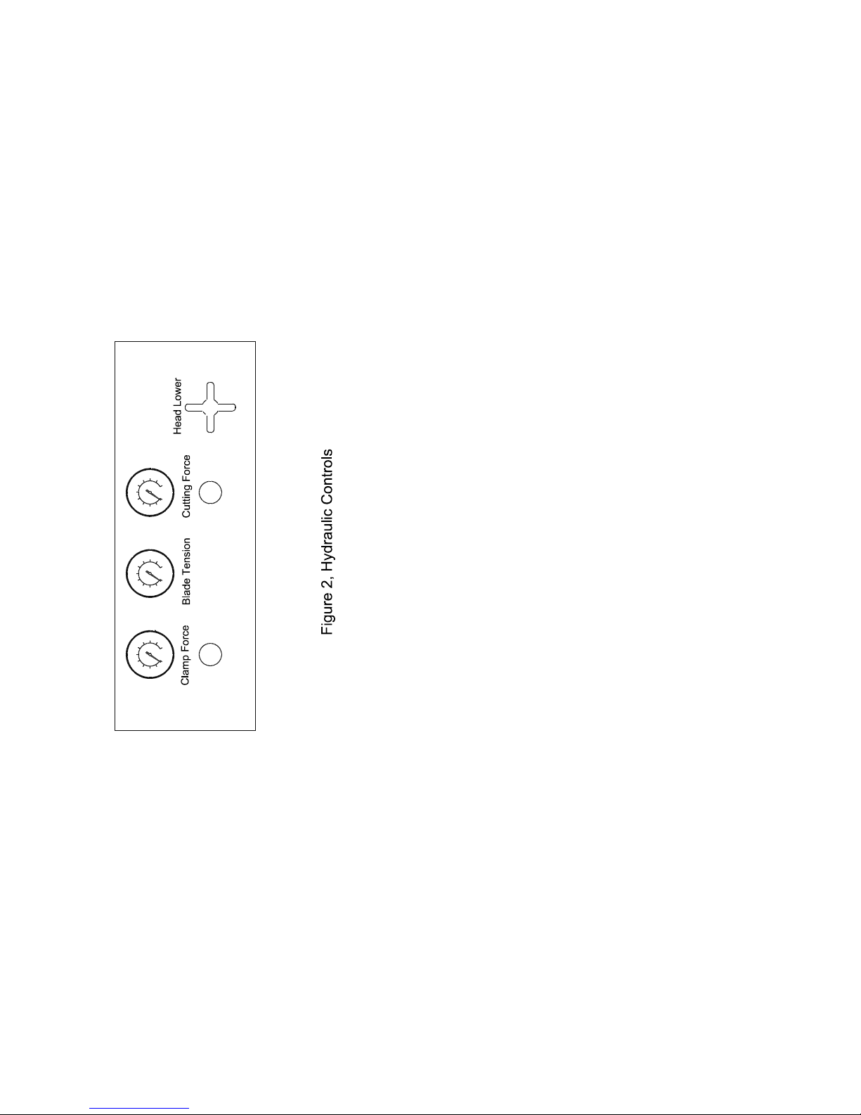
B. Operator Controls.
8. Dam around each screw jack and
pour grout up to the base of the machine to
prevent shifting.
III SAFETY and OPERATION
Few safety devices benefit the careless
worker. Safety is an attitude either accepted
or rejected by the operator.
A. Safety.
For the operator who abides by his local
shop safety practices add the following,
applying to this machine.
1. Lock or tag out the electric disconnect during routine maintenance.
2. Replace guards and safety devices
removed during maintenance, before returning the machine to service.
3. A qualified assistant operator need
not be at the controls of this machine when
the regular operator is not. Authorize other
workers in the area to shut down the
machine with the Emergency Stop control in
the event of conditions of hazard.
CNC SAW OPERATION
The following is a quick start guide to begin
cutting material within minutes after applying
machine power. This machine is designed
using state of the art technology for high
quality cut parts. The color touch screen
offers simple operation with operator
prompts and diagnostics directing new and
experienced operators like no other sawing
machine. Most screens have help pages
associated with them for new operators that
provide the necessary information to operate
the machine without the written manual. The
attached manual provides advanced help
and documentation to assist the touch
screen prompts and help pages. All faults
and prompts are logged with time and date
stamps to trace machine operation history.
More to follow in the operation manual.
1.) After wiring the machine, leveling,
connecting the vise cylinders, and turning
on the disconnect, the machine is ready to
operate.
2.) Push the hydraulic start. The machine
hydraulics will start. Be sure the E-stop is
pulled out and the stop cable is reset.
4. Do not allow casual climbing or
leaning on the machine. Slippery coolant
covered surfaces are not detected until too
late to prevent the slip.
5. Wear heavy protective gloves
during blade change for positive control of
the blade.
Guard against all other body
contact with
the blade. Never wear gloves while
operating this or any machine tool.
6. Always wear eye protection
when operating this equipment.
6
3.) The home carriage screen will appear
after the hydraulics start. Move the carriage
forward until the “home OK” appears.
4.) Put the blade on the machine and then
tension it.
5.) The machine is now ready to make a
manual cut or an automatic cut. The
operator prompts and help screens will guide
from this point as well as the following
detailed instructions.
Note: The pages after page 20 in this
manual show each touch screen and contain
the help screen for each as well. The
operator should look at each screen and
read the help instructions before operation.
The green dot on the blade tension dial is
reference for proper blade tension.
The needle must always be at the green dot
during sawing to maintain blade tension.
See page 17 to adjust blade tension to blade
manufacturer specifications.
Cutting force dial is reference for blade force
important factor.
For fast, smooth sawing and lower cost per
cut, request a reliable blade supplier make
test cuts on the machine and the work piece
with his recommended blades.
Normally a thin section of work requires a
light sawing force and a wide section greater
force.
However, as the blade guides spread wider
for bigger stock, a longer distance between
the guides, the blade loses some of its
rigidity, or blade beam strength.
On wide stock use a lighter sawing force and
use only new blades which require less force
to make a satisfactory cut. Applying more
sawing force to penetrate a wide work piece
causes blade run out--a crooked cut in the
work piece.
As blades dull sawing wide work, replace
them with a sharp blade.
Set dulled blades aside for sawing smaller
work where the short span between the
guides provides greater saw blade beam
strength, rigidity, and makes cuts within
tolerance. Follow blade manufacturer
instructions for breaking in a new blade.
For more details on sawing force, see Blade
Selection Manual 900409 in this binder.
against the work piece.
Turn the sawing force control right or left to
increase or decrease sawing force on the
work piece.
Two metering valves, one in each guide arm
just above the blade, monitor the sawing
force.
Carefully determine sawing force. It is a very
Saw head approach feed control adjusts saw
head feed down to the work piece.
This control valve fully closed, the saw head
will not move.
The control fully open, the saw head will
come down at it's top speed. At the point the
blade contacts the work piece and begins
sawing, the dual hydraulic sawing force
system takes over.
Guide Arm Positioning.
When positioning the blade guide arm make
certain the area under both arms is clear of
obstruction.
The right guide arm and vise jaw stay at the
right side of the saw bed, next to the drive
wheel.
The left guide arm and vise jaw adjust to
work piece size.
7

For maximum safety and for support of the
blade while sawing, move the left guide arm
close to, but not touching the left vise jaw.
Allow a half inch extra space to open the
vise jaw.
To move the guide arm, loosen the hand
lever above the guide arm, releasing the
clamp. Slide the arm to place and tighten
the hand lever.
C. Operating Sequence.
Do not operate this machine before studying
manuals in this binder.
Follow the sequence closely, so it is
automatic as you become familiar with the
machine.
Blade installation procedure is in the maintenance section under mechanical
adjustments.
1. Move the blade guide arm far left.
2. Set all controls to Off, Stop and Manu-
al.
3. Switch on the electric disconnect.
4. Start the hydraulic pump.
5. Raise the saw head.
6. Tension the saw blade.
7. Adjust the machine to the work per
part "B", clearance for blade and guide arm,
number of pieces, length and any optional
equipment.
8. Open the vises.
9. Switch the machine mode to manual.
and select "Off" on their respective switches.
If an outboard vise or a holddown is used,
and the trim-cut material is too short to
clamp, leave the outboard selectors in the
"Off" position until the Auto cycle pushes the
stock out from under the holddown. Then
select "Clamp".
12. Start the saw blade and adjust blade
speed for the work piece.
13. Adjust sawing force and close the
feed control valve.
14. Press the saw head feed control and
open the approach feed control valve slightly
to feed the blade into the work piece slowly.
15. Monitor the chips, thin and curled.
Adjust the sawing force.
16. Switch the barfeed control from
Manual to Auto while making the first trim
cut. The machine can be placed in Auto
mode operation from a stand still by:
A) Selecting "Auto" on the mode switch.
B) Clamping the saw vise.
C) Starting the blade.
D) Pushing "Cutting Head Lower". The ma-
chine will now cycle automatically.
10. Move the work piece under the blade
for a trim cut.
11. Adjust clamping force for the work
piece and clamp the vise jaws. If there are
selectors for optional holddowns or for an
outboard vise, select "Clamp" on the selector
switch to enable them for automatic operation. If any of the outboard vises or
holddowns are not being used, manually
move them to a position as to not interfere
with the automatic operation of the machine,
8
17. The machine will automatically saw
and feed a pre-set number of pieces, or, the
out of stock limit switch senses the end of
stock passing through the barfeed. One or
the other will shut down the machine.
If the 2 or 3 stroke option is used, a short
delay will be noticed while the carriage vise
is clamping. This allows time for the out of
stock limit to be made.
If the counter, or limit switch are not used
and manual shut down is necessary, turn the
mode selector to "Manual". This locks out all

cycles except the saw head. The saw will
complete the cut, return to the raised
position and the system will shut down, just
as the machine functions with a manual cut.
18. Open the vise jaws and move the
work as necessary.
weld. Automatic blade welders will get out of
adjustment, or an inexperienced welder
operator may improperly anneal the weld.
If this is not the problem, see the maintenance section on sawing force and blade
wheel alignment.
19. Shut down the machine with the
Emergency Stop control.
D. Trouble Shooting.
Common band sawing problems listed
here give instructions for correcting the
problem.
Consider a problem carefully.
Get at the underlying cause of a problem
rather than remedy a series of side effects.
1. Scale on the work piece.
Hot-rolled steel will have a degree of mill
scale. On low carbon steel the scale does
not affect sawing rates, but the scale dulls
the saw blade teeth. Remove scale from the
sawing area.
2. Hard surfaces.
Torch cutting and improper grinding some
steel creates a case-hardened shell a few
thousandths of an inch thick. Sawing
through it will dull saw blade teeth. Saw and
change blades as they dull is the only solution, until the hardened area saws through.
3. Crooked sawing.
If a new blade saws crooked, or begins to
saw straight but after several cuts starts to
saw crooked and results are worse with each
cut, see the above paragraphs, the blade
selection manual and the maintenance
section on sawing force.
A machine not being level is a major cause
of getting crooked cuts. See leveling and
anchoring section, page 4, for more
information.
4. Broken blades.
Check to see if blades are breaking at the
5. Stripped teeth.
This is usually caused by improper sawing
force and blade speed.
See the blade selection manual, and the
maintenance section for a sawing force
check.
6. Poor blade life.
Blade speed too fast for the work piece is
the usual cause of poor blade life. See paragraphs 1 and 2 in this section.
7. Erratic saw head feed.
Uncontrollable saw head feed into the work
piece can be:
a) Defective blade welding, defective weld
grinding, blade teeth points stripped or
wrong blade for the work piece.
b) Lubrication, section IV.
c) Leveling and anchoring, sec. II.
d) Blade guide clearance, blade linkage or
metering valve. See maintenance section IV.
e) If erratic feed is still a problem, look for
brass frame thrust screw excessive wear.
Brass marks front and back of the left post
the saw head rides on, or brass dust at the
base of the post means the machine is not
level, or thrust screws are too tight against
the post.
1) Loosen lock nuts holding the thrust
screws, front and back of the left post frame.
Remove the thrust screws.
2) File the post contour from the face of the
9

thrust screws.
3) Turn the rear screw in first, bringing it up
to the column. Push gently on the frame to
feel contact with the post.
4) Hold the frame with the rear screw
against the post. Turn the front screw to the
post, lightly, then back it off cTH turn. c
TH
turn is the required .008 clearance between
the post and screws in the frame.
5) Tighten the lock nuts and check the saw
head for smooth feed.
8. Saw head stall.
If the blade comes to the work piece and
starts the cut but seems to float without
sawing, check the following malfunctions.
a) Make sure the blade is sharp, and the
proper blade for the work piece. Too much
sawing force applied to a small tooth blade
on a wide work piece fills saw tooth gullets
before the blade clears the work piece to
empty the gullets.
Chips locked in the tooth gullet, still in the
blade kerf, force teeth tips up away from the
cut, causing the blade to float through the
kerf. Change the blade to one with fewer
teeth and larger gullets, or use less sawing
force to form smaller chips, at the risk of
heating the blade to the point of hardening
the work piece.
will not move, or come down only slowly.
See the maintenance section for a blade
guide inspection.
e) Silt will by-pass a plugged hydraulic fluid
filter and accumulate in the metering valve.
Check the hydraulic fluid reservoir for a
milky-white color. Water or coolant in the
fluid will contaminate the entire system.
See hydraulic fluid level and sawing force in
the maintenance section.
9. Saw blade stall.
If the blade jams in the cut it is either the
wrong blade for the work piece, too much
sawing force for the blade or blade tension is
improper.
Correct the sawing practice.
Wait five minutes and press the motor starter
reset control. If the blade stalls with the
motor running, shut the machine down. Free
the blade from the kerf and tension the blade
properly. Rotate the work piece a few
degrees so the blade will not hang up in the
same kerf.
10. All system stall.
The hydraulic pump motor is thermal overload protected to shut down the system if the
motor overheats. Let the motor cool five
minutes and press the reset control. Also
see electric maintenance section "D."
b) Monitor the sawing force.
Use only 30 to 50 pounds of sawing force
and use the proper blade for the work piece.
c) Look for a hydraulic line kink from the
blade guides back to the control console,
limiting hydraulic fluid flow from the metering
valve to the control valve.
d) Look for dirt lodged in the blade guides,
preventing the metering valve from functioning. Keep the guides clean. Dirt and chips
blocking the metering valve linkage forces
the metering valve closed and the saw head
10
11. Saw head drift.
It is normal for the saw head to drift down
while sitting idle for a time.
Remove all work from the vise jaws, tools
and other material from the work bed at the
end of each shift.
Unauthorized machine use or drift down, the
blade coming into contact with material left in
its path, may destroy the blade and the
material.
IV MAINTENANCE
To assure smooth running machinery and
save hours of downtime and repair costs

follow inspection, adjustment, lubrication and
maintenance outlined here.
Check that all machine cycles function
through completion, not partly blocked.
A. Lubrication.
The lubrication chart in the back of this
manual depends on shop conditions and machine use.
1. Fluid levels and filters.
Routinely check fluid levels and filters. Lock
or tag out the electric disconnect switch.
a) Hydraulic fluid.
Check the fluid level with the saw head lowered and the machine turned off. Fluid showing in the screen, ½" to 1" from the top of the
top is proper level. Bring the fluid level up to
the this level with Mobil DTE-24.
Low fluid level allows air to enter the pump,
causing dieseling, cavitation and a ruined
pump.
Dirty hydraulic fluid is usually because the
reservoir filler cap is not in place.
Dirty hydraulic fluid causes valves to stick
and orifices to plug. Machine adjustments to
improve poor sawing will constantly change.
If hydraulic fluid inspection reveals dirt, or is
milky-white with water or coolant, contamination is in all lines and cylinders. Break primary connections and blow out the lines. Drain
and rinse the reservoir twice with fuel oil.
Swab out the reservoir and fill it with clean
fluid. Change the hydraulic fluid filter cartridge.
Activate all cycles several minutes to flush
out the machine.
Repeat the process five times, or until there
is no dirt or discoloration in the hydraulic
fluid.
Change the filter cartridge again.
Install a chain and lock on the reservoir filler
neck and cap.
Hydraulic fluid temperature over 130° is a
malfunction.
Check the fluid level.
Check the fluid for proper viscosity.
b) Hydraulic fluid filter.
Original equipment hydraulic fluid filter
cartridge (part number 911231) furnished
with this machine is a spin-on type with a
classification of three micron, absolute,
filtering .003 contamination out of the
system.
Replacing the filter cartridge with a rating
greater than three micron, ten micron for
instance is a popular filter, will downgrade the system and life expectancy of
the machine.
Change the filter cartridge once a year
(2,000 hours) for a trouble-free operation.
Locate the filter cartridge mounted inside the
lower front panel of the operators console.
Unscrew and discard the contaminated filter
and gasket. Check the gasket on the new
filter cartridge for damage. Wipe a thin film
of fresh fluid on threads and gasket of the
new cartridge and turn it on the filter system,
hand tight only. Make certain the cartridge
bottoms out on the filter system head.
c) Gear case oil.
See the contents page for the drive gear
reducer bulletin.
NOTE: Drain the blade drive reducer case
after the first 80 hour run-in period.
Flush the case with a light flushing oil. Filter
the old oil, or replace it with fresh oil.
Each 2,000 hours of operation drain the
reducer cases, flush, and fill with fresh oil.
Check gear case fluid levels at the sight
glass on the front of the case or pipe plug at
the side of the gear case, or oil standing in
the filler elbow. With the machine shut down
oil must be visible in the filler elbow, or seep
out the loosened pipe plug.
Add fresh oil as necessary to bring the level
up.
W. F. Wells and Cone Drive-Textron use and
recommend using only Mobil SHC-634
11

synthetic oil.
It is normal for gear reducers to operate at
housing temperatures up to 200 degrees.
Keep finned areas on the case clean to allow
maximum heat dissipation.
Keep breather plugs on top of the cases
clear of dirt to avoid gear case oil
contamination.
B. Coolant Fluids and Pump.
Caution: During machine set up and trial
running fill the coolant tray. Coolant fluid is a
heat sink for the pump and it must not be
operated unless the coolant tank is full of
coolant. Routinely clean the coolant tray and
pump screens. A blocked screen will stall
the pump. A damaged screen allows chips
to block or enter the pump chamber, ruining
the pump within minutes.
This machine has a 15 gallon coolant tray
capacity.
Consider coolant type and machine use
before filling the tray. Some fluids
deteriorate more rapidly than others. The
work piece and the blade determine
coolant/lubricant type.
There are coolant fluids and there are cutting
fluids.
Faster blade speeds require efficient coolant
to prevent saw blade overheating.
Increased tool surface speed makes the
cutting edge run hot. Without proper coolant
blade metal temperature passes critical at a
given point. Blade teeth soften and dull.
1. Straight cutting oil.
Slow blade speeds for hard metals and saw
blades that remove a large chip from the
work piece require more coolant/lubricant.
At these slow speeds high lubricity straight
cutting oil is popular.
Do not use straight cutting oil in this machine
unless factory labels clearly show machine
equipment includes oversize coolant pump,
lines and nozzles.
2. Water soluble oils.
Water soluble oils offer good cooling as well
as good lubrication.
Use one part oil to fifteen parts water for
most steels.
Use one-to-one water and soluble oil for tool
steel sawing.
This machine can use this fluid.
3. Synthetic oils.
Synthetic oils, without chemical solution, are
similar to water soluble oil capability and
dependability and used in the same manner.
Use one part oil to fifteen parts water for
aluminum sawing. A drawback to some
synthetic oils is animal fat in the formula
which deteriorates in time, and at high
temperatures, causing a breakdown of the
fats, creating an unpleasant odor.
This machine can use this fluid.
4. Chemical solutions.
Some cooling/cutting fluid used in high
speed aluminum machining and freemachining alloys contain chemical wetting
agents.
The application is useful but side effects are
harmful to the work piece and the machine.
Do not use chemical coolant in this machine
unless factory labels clearly show machine
equipment includes corrosion resistant
pump, hoses, seals and paint.
C. Mechanical.
1. Blade installation.
WARNING: Do not install a blade on this
machine before completing the pre-operation
check-out.
See the Saw Blade Selection and
Application manual to select the proper
blade for the work piece.
For maximum feed, speed and blade life,
request a reliable blade supplier conduct test
sawing with his recommended blades on the
machine and the work piece.
a) Start the hydraulic pump and release
12

blade tension.
b) Raise the saw head so the guide arms
clear the vise jaws.
c) Lock or tag out the electric
disconnect switch. Always disconnect
power before touching the blade or
opening the wheel covers.
d) Open the blade wheel guard doors.
Blade wheels rotate counterclockwise as
seen from the operator's console, drawing
blade teeth through the work piece from left
to right against the stationary vise. Wear
heavy gloves for positive control of the
blade. Hold the blade in front of the wheels
with teeth pointing to the back of the
machine. Teeth on the lower blade loop must
angle right, toward the drive wheel.
If teeth on the lower loop point to the back of
the machine but angle left, toward the
tension wheel, the band is inside out.
Reverse it.
For safety, clear personnel from the area.
Loop the band over a handy guard post or
trash barrel. Twist the band, as far around
the circumference as necessary, until the
band snaps over.
e) Again, hold the blade in front of the
wheels with teeth pointing to the back of the
machine. Teeth on the lower loop must angle
right, toward the drive wheel.
f) Place the top of the loop over the frame
posts, into the blade guard channel, and
onto the wheels.
Pull the back of the band up next to the
wheel flanges.
g) Start the machine and jog the tension
control just enough to take up slack in the
band. Shut down the machine.
This machine is equipped with door interlock
safety switches. The blade cannot be started
with the blade guard doors open.
h) Open the blade guides with the thumb
lever cap screws in the face of the guides.
One guide at a time, grasp the blade firmly
each side of the guide, twist the teeth down
and bring the back edge of the blade up
between the guide blocks.
i) Tighten the thumb lever cap screws in
the guides, check that the back of the blade
is next to the wheel flange.
j) Close the blade guard doors.
Start the machine and run the blade 30
seconds.
k) Shut down the machine.
Check that the back of the blade is close to,
but not scrubbing on the wheel flanges.
.010" to .030" clearance is ideal. Check
blade tension before each saw cut.
2. Blade wheel alignment.
Wheel alignment is not part of a routine
machine setup for a sawing operation.
Factory-aligned, inspected and tested
wheels, blade and guides require no
maintenance.
The usual cause of misalignment is
experimenting or bumping the wheels or
guides with the work piece or material
handling equipment.
Routinely check the wheel flanges for wear.
Be alert to audible and visual changes in
machine operation. A high-pitched metal-tometal scrubbing sound coming from the
wheel guard doors is the back of the blade
scrubbing on the wheel flange. The blade
will wear the flange from the wheel before
the blade breaks.
When checking wheel alignment use only a
new blade, known to be straight. A used
blade may have developed a camber,
making results of an adjustment useless.
To inspect the wheel flanges or to adjust
either wheel, raise the saw head so the
wheel guard doors clear the control console.
Release blade tension and lock or tag out
the electric disconnect switch.
13

a) a. To adjust the tension wheel, see
the contents page for the tension assembly
print and Figure 3.
(1) Open the tension wheel guard door.
The tension wheel mounts on a sliding plate.
Locate and loosen two lock nuts, under the
wheel spokes, top and bottom of the outside
edge of the slide plate.
(2) A set screw beside each lock nut is a
spacer for the plate.
See "A" Figure 3, above.
The blade is running too close to the wheel
flange, scrubbing, the wheel rim too far from
the frame plate on the outside. Turn both
set screws counterclockwise, equally, ¼ turn
each, drawing the outside rim of the wheel
closer to the frame plate.
NOTE: Do not overcompensate. Turn the
set screws equally ¼ turn only.
(5) Tighten the lock nuts.
Check the clearance as in step (3).
b) To adjust the drive wheel, see the
contents page for the drive assembly print
and Figure 4, below. The drive wheel mounts
on the output shaft of the gear reducer,
bolted to the back of the saw head frame
plate. Adjusting the gear case adjusts the
drive wheel proportionally in the same
direction.
1) In the cabinet at the back of the saw
head behind the drive wheel, locate four hex
head screws on the gear case, locking
threaded spacers and the gear case to the
The blade is running too far away from the
wheel flange, the wheel rim too close to the
frame on the outside. Turn both set screws
clockwise, equally, ¼ turn each, pushing the
outside rim of the wheel away from the
frame plate.
NOTE: Do not overcompensate. Turn the
set screws equally ¼ turn only.
(3) Tighten the lock nuts.
Close the wheel guard doors.
Tension the blade. Start the blade and run
it 30 seconds.
Shut down the machine.
Check that the blade is not still running too
far away from, or scrubbing on the wheel
flange.
(4) See "B" Figure 3, above.
saw head
frame plate. On the side of the gear case
next to the cabinet wall, hold the threaded
spacers and loosen the two hex head lock
screws top and bottom of the gear case, one
or two turns.
14

2) If the blade is running too far from the
wheel flange, the wheel rim low on the
outside, too close to the frame plate, see
"A," Figure 4, below, turn both threaded
spacers, equally, top and bottom of the case
¼ turn counterclockwise, drawing the gear
case closer to the frame plate, pushing the
wheel rim away from the frame plate. NOTE:
Do not over-compensate. Turn
the threaded spacers ¼ turn only.
3) Tighten the hex lock screws.
Tension the blade and run it 30 seconds.
Shut down the machine. Check that the
blade is not still running too far away from, or
scrubbing on the wheel flange. .010" to .030"
clearance is ideal.
4) If the blade is running too close to the
wheel flange, scrubbing, see "B," Figure 4,
below, the wheel rim high on the outside,
turn both spacers clockwise, equally, ¼ turn,
pushing the gear case away from the frame
plate, drawing the outside wheel rim closer
to the frame plate.
5) Tighten the hex lock screws and check
the clearance as in step (3).
3. Blade tension adjustment. Factory-set
blade tension is for size and type blades
used in general purpose sawing.
The blade tension control must be in the
Tension position while sawing.
The dial indicator needle at the operator's
control console must come exactly to the
green dot on the dial.
If the tension indicator needle does not
reach, or passes the green dot, inaccurate
sawing or blade break results.
For maximum feed, speed and blade life
consult a reliable blade supplier for recent
research in tooling.
Request test cuts on the machine and the
work piece with his recommended blade.
Tension the blade to manufacturer specifications with a precision tension gauge
mounted on the blade.
The supplier will install his gauge on the
blade.
Tension the blade.
When the needle on the control console dial
reaches the green dot, the blade supplier will
determine from his gauge whether to
increase or decrease tension for his recommended blade.
To change blade tension, remove the cover
on the lower front of the operator's control
console.
Increase or decrease blade tension with the
double lock knob hydraulic valve, inside left
wall of the cabinet.
With tension adjusted for the choice of
blades, lock the valve.
Move the green dot to the new needle
location on the face of the gauge.
When changing blade types for other work,
tension the new blade to blade manufacturer
specifications.
Before each cut, make sure the tension
needle is at the green dot.
4. Sawing force check.
The dual hydraulic servo-controlled sawing
force system measures work piece
resistance to the blade while sawing,
applying uniformly controlled force to the
blade for accurate sawing regardless of
configuration, size or type of material.
Sawing force range for this machine is 0 to
400 pounds, adjusted at the operator's
control console.
See controls 20 and 21 on page 6.
Too much or too little sawing force results in
uneven sawing or broken blades.
With each blade change, inspect the blade
guides for chips and sludge build up. They
prevent blade guides and metering valve
linkage from working properly, producing
other than the sawing force adjusted at the
control console.
Sludge in the coolant or hydraulic fluid, a
malfunctioning sawing force dial, metering
valve or linkage from the blade to the
metering valve alters the dial reading from
actual force the blade applies to the work
15

piece.
Use preventive maintenance.
Check the sawing force.
a. Tension the blade, spread the guide
arms and vise jaws. Raise the saw head.
Do not start the blade.
b. Close the saw head approach feed
control valve and press the saw head feed
control.
c. Open the saw head approach control
valve just enough to lower the saw head
slowly.
Tap the blade lightly at the guides, seating
the blade in the metering valve linkage.
Sawing force is adjusted by lengthening or
shortening the linkage that runs from the
metering valve to the carbide back-up
slipper. See drawing 010370A.
The metering valves close and the sawing
force/saw head stops applying force on the
saw blade.
To verify that the metering valve is working,
lift the linkage as shown in drawing
010370A. The frame should stop coming
down.
If more than .040" of travel is needed to stop
the frame, adjust the linkage as described in
section 8.
If the tensioned blade only partly returns
when pushed down out of the guides,
without hanging up, continue this check.
Linkage travel must not be less than .030"
and not more than .040".
More than .040" travel, the linkage too short,
will not control the metering valves and may
let saw teeth enter between the blocks, ruining the blade and the blocks.
Less than .030" travel, the linkage too long,
will hold the metering valves closed, hold the
saw head in suspension or come down only
slowly.
Check the linkage travel.
a) Fasten a dial indicator to the guide
arm with the contact point resting on the
back edge of the saw blade.
Set the dial to "0" and place a block of wood
under the blade next to the guide arm.
Use a piece of round stock in the blade tooth
gullet and bring the saw head down on the
block of wood.
When the saw head stops, read the dial indicator. Check both guides.
b) If the blade is not hanging up in the
guides and blade travel at both guides is
.030" to .040", problems with the sawing
force check is not with linkage travel from
the back of the blade to the metering valves.
Go to step 7 for a metering valve check.
5. Metering valve linkage check.
If the sawing force check failed, linkage from
the back of the blade to the metering valves
may be worn or the blade guide blocks may
be pinching the blade.
Be certain the guides are flushed clean and
try forcing the tensioned blade in and out of
the blocks.
Under full tension the blade must only partly
return back up into the guide. If it hangs up,
sticks or slides too freely between the
blocks, go to step 6 for a blade guide check
before continuing here.
16
c) If linkage travel is more than .040" it is
too short to close the metering valves. The
probable cause is a blade track worn in the
backup slipper greater than .030". Go to
step 6, dismantle and inspect the guides and
backup slipper. If the backup slipper is not
worn adjust the linkage during the metering
valve check.
d) If blade travel is less than .030" the
linkage is too long to let the metering valves
control sawing force. The probable cause is
a backup slipper replacement and shims

added to the linkage, or, guide blocks
binding the blade. Go to the next step for a
blade guide inspection.
6. Blade guide inspection.
NOTE: Consider this and the next two items
on linkage and metering valve inspection
before making adjustments.
Routinely, when changing blades, check the
guide rollers and backup slipper for dirt and
sludge and proper guide roller clearance.
Normally, guides require adjustment only
after years of wearing in.
If stock or material handling equipment near
the machine bumps the guides they will
break or misalign and require adjustment or
replacement.
Following are three preventive maintenance
checks.
a. Clean, inspect and adjust the guide
rollers.
(1) Guides are factory set .001" wider
than the blade thickness.
.042 blade thickness requires .043 guide
roller clearance.
See the contents page for the blade guide
print.
Guide rollers adjusted too tight or too loose
cause erratic sawing rates, inaccurate cuts
and broken blades.
Release blade tension and lock or tag out
the electric disconnect.
(2) Remove the blade and flush out the
guides.
(3) Check roller clearance with feeler
gauges, or, assemble a new blade on the
machine. Tension the blade.
Look for a tight or loose fit.
Force the tensioned blade down out of the
guide. It must only partly return up into the
guide rollers when released.
(4) Look for blade movement in the sawing area between the guides.
Twist the blade back and forth between the
blade wheel and guide.
(5) If feeler gauges read correct, or if the
tensioned blade only partly returns when
pushed down out of the rollers and there is
no blade movement between the guides
when twisted from outside the guides,
problems with the sawing force check are
not with guide roller clearance.
Go to item 8 on metering valve linkage
check.
(6) If step (5) failed, adjust the guide rollers. Raise the saw head.
Release blade tension. Lock or tag out the
electric disconnect switch.
(7) Release the carbide side inserts so
they can float with the blade during adjustment.
(8) One roller on each guide rigidly
mounts to the casting and is not adjustable. The companion roller adjusts on a
cam shoulder bolt. Loosen the lock nut on
top of the high side of the roller casting,
unlocking the cam bolt. Turn the cam bolt
at the bottom of the roller.
(9) Use feeler gauges to adjust clearance
between the rollers .001" wider than blade
thickness, or go back to step (3).
Caution: Rollers gripping the blade too tight
prevent the metering valve from controlling
sawing force; the blade will snake through
the rollers, inaccurate sawing and blade
break results.
(10) Install and tension a new blade on
the machine. With rollers adjusted, hold the
floating carbide side inserts snug against the
blade and draw them up to the roller casting
with the hex head screws.
Lock them in place against the blade with the
socket set screws at the side of the guide
casting.
17

b. Horizontal guide adjustment.
It is critical when making this check to align
the vise jaws 90° to the saw bed.
(1) Use a combination square with the
head centered. Place the 90° side of the
head into the vise slide in the saw bed and
bring the face of the stationary vise jaw to
square with the combination blade.
Make the same adjustment on the movable
vise jaw.
nut and adjust the plate and blade into
alignment with the blade wheels, square to
the vise jaws.
Use the combination square against the
blade and vise jaws to check the alignment.
See step (1).
c. Vertical blade/guide adjustment.
After a vise jaw adjustment to align the blade
square to the vise jaws, rotate the blade
back square with the saw bed.
(2) With vise jaws aligned square to the
saw bed, move the 90° side of the square
head to the end of the combination blade.
Place the head against the stationary vise
jaw and bring the square blade up against
the saw blade to check for square.
If the blade is square to both vise jaws, go to
step c.
(3) If the saw blade is not 90° to both vise
jaws discover which guide (or both) is out of
alignment. Mount a new blade on the
machine and tension it. On top of the guide
beam, loosen both guide arm clamps. The
tensioned blade will draw the guides into
alignment. Check the blade, square to the
vise jaws. Tighten one guide arm clamp at
a time to see which arm is pulling the
tensioned blade out of square to the vise
jaws.
(4) Determine which guide (or both) to
adjust to align the saw blade to the vise
jaws. Clamp the arm at the guide beam and
see the contents page for the blade guide
print.
(1) Place a dial indicator on the saw bed
near the guide, with the indicator contact
point against the saw blade, directly above
the tooth gullet.
(2) Set the dial to "0.
Open the saw head control valve slightly to
bring the blade down across the dial
indicator contact point slowly.
If the dial indicator reads "0" bottom to top of
the blade at both guides, go on to item 8,
metering valve linkage inspection.
(3) If step (2) failed, adjust any difference
in the dial indicator reading, bottom to top of
the blade, to "0." Locate the adjusting screw
above the guide rollers and the lock nut
behind the guide above the blade.
See the blade guide print. Loosen the lock
nut and turn the adjusting screw to tilt the
roller assembly, bringing the blade to vertical
square with the saw bed. Visually check the
alignment with the combination square.
Check the alignment with the dial indicator
for a "0" reading from bottom to top of the
blade as it passes over the indicator tip.
(5) Loosen the hex screw at the top of
the plate holding the guide assembly to the
arm and the hex nut immediately under it,
unlocking the assembly plate and cam bolt,
allowing the assembly to rotate into
alignment.
(6) Locate the hex head cam bolt on the
opposite side of the plate from the hex lock
18
7. Metering valve inspection.
See the contents page for the blade guide
and metering valve prints.
With each blade change, inspect the blade
guides for chips and sludge build up that prevent metering valves and linkage from working properly.
If the sawing force check failed check the
blade guides and linkage before making this

check.
Particles flaking from walls of hydraulic lines
may have accumulated in the sawing force
system. Check the change date on the hydraulic fluid filter cartridge.
a) Lower the saw head and lock or tag
out the electric disconnect. NOTE: If the saw
head will not come down because of clogged
metering valves, block up under the guide
beam to prevent the saw head from dropping
during the next step.
b) Remove hoses from the metering
valves and hex head screws holding the
valve to the guide arm.
c) Lift the valve body from the guide
block; remove the socket head screws from
the valve cap, shown in foldout 010370.
d) Pull the plunger from inside the valve
body and wash all parts in mineral spirits.
Inspect the seals for embedded particles.
Replace them from 2,000 hour spare parts if
necessary.
e) Cleaning and replacing worn parts
from the blade guide blocks and backup
slippers, up to the metering valves, is a
complete overhaul of the sawing force system, and, properly accomplished, brings
about proper results with the sawing force
check, step 4, page 18.
D. Electrical Maintenance.
WARNING: COMPLETE THE
PRE-OPERATION CHECK-OUT BEFORE
STARTING THIS MACHINE.
During machine installation and trial running,
fill the coolant reservoir. Coolant is a heat
sink for the pump and it must not operate
unless the coolant tank has adequate
coolant. See maintenance section part "B"
on coolant fluids.
A qualified electrician must make electric
hook up and adjustments to this equipment.
See machine voltage, labeled on the electric
cabinet door. See the contents page for the
electric print.
1. After electric hookup check hydraulic
pump rotation.
a) Check hydraulic pump rotation in the
cabinet behind the operator control console.
Rotation must be in the direction of the arrow
on the pump housing. With the hydraulic
pump rotating in the correct direction, the
drive wheel should be rotating counterclockwise; if not, reverse wiring at drive motor.
2. Routinely check limit switch mountings
for dirt and loose fasteners which could
cause a later malfunction.
3. The electric system for this machine
consists of a programmed computer
receiving and coordinating signals from
operator controls and limit switches.
The signals send current to solenoid coils in
valves controlling hydraulic fluid flow to
cylinders maintaining blade tension, moving
the saw head, vise jaws, barfeed, outboard
vise, vertical holddown clamps and powered
roll tables.
Automatic machine functions start the next
function. A function may look complete but
if a limit switch does not trip, or is faulty, the
computer will not receive the signal. The
solenoid coil cannot activate the valve to
shunt hydraulic fluid to cylinders and hydraulic motors. Usual cause is a burned out
solenoid coil or sticking
E. Parts and Service.
Most-used replacement parts are available
from factory stock with same-day shipment.
Service is available by telephone conference
or a service call to the machine site.
1. Parts.
For 95% insurance against downtime, the
lists show most commonly used parts. Pro-
19

gram them into inventory on a replace-asused basis.
2,000 hours is equal to one eight hour shift
working for one year.
Account for spare parts. Enter them into
inventory with a zero stock level reordering
system to assure availability when the need
arises.
Write additional part numbers assigned for
plant systems compatibility on the lists for
reference.
Shelf life for parts listed is indefinite, only so
long as packaging is intact. Look for packaging opened for inspection, authorized or
otherwise. Repackage parts in suitable
containers and identify them to preserve
usefulness when the need arises.
Except fluids and filters, expect machine life
of those parts planned for replacement to
exceed the hours shown by as much as
three times.
Variables are machine operator and original
equipment manufacturer workmanship reliability.
Nuts, bolts and common parts normally
obtained from hardware or mill supply stores
may not show a part number on the prints,
but will show a part description for local
source replacement.
If a needed part is not identified, provide our
parts department with a detailed description
of the part, where it is on the machine and
what it does in operation. This will be
enough information for our parts department
to identify and supply the part.
2. Service.
Only preventive maintenance is required for
many years, with expendable belts, bulbs,
filters and blade brushes replaced by maintenance personnel. solenoid valve.
Manual machine functions may operate
when automatic sequences will not.
If the machine will not function in the manual
mode, begin checking at the electric source.
Trace through fuses, motor overload and
limit switches to solenoids. If the solenoid
plunger will activate the valve, replace the
burned out coil. If the plunger will not
activate the valve, replace the frozen valve.
See spare parts.
Also, see optional equipment possibilities.
4. A blown fuse in the 115v line, 5a,
under the transformer in the electric cabinet,
is probably caused by dirt or chips inside the
coolant pump. Unplug the coolant pump at
the in-line disconnect. Replace the fuse and
run the machine.
If the fuse holds without the pump, clean all
screens and the coolant pump rotor to determine if the pump can be salvaged.
If the fuse will not hold, look for a short in the
control panel at the operators console.
It is vital to machine life and sawing efficiency that machine operators and maintenance
personnel read and have access to the contents of this binder.
If a sawing or machine malfunction occurs,
try to get at the cause of the problem rather
than remedy a series of side effects.
The index in this manual is topical, offering a
solution to common problems.
If a machine problem cannot be resolved
by in-plant personnel, do not hesitate to call
our service department. A factory-trained
and qualified person will resolve the malfunction on the telephone.
For Parts or Service
Telephone 269-279-5123
Fax 269-279-6337
parts@wfwells.com
www.wfwells.com
For faster service, furnish the machine
model and serial number from the
identification plate on the machine bed.
Note your serial number here:
Model F-1620-A CNC
SEE SPARE PARTS LISTS NEXT PAGE
20

MODEL F-1620-A CNC Recommended Spare Parts List
Group I, 2,000 Hours
Qty Part# Description
1 900091 Blade brush.
2 901023 Blade brush bearing.
1 908965 Blade drive belt.
8 901204 Blade guide rollers, 1¼" blade.
2 292290 Blade backup slipper, carbide
4 292420 Blade guide side inserts, 1¼" blade
1 911231 Hydraulic system filter cartridge.
1 921530 Saw head limit switch assembly.
2 900811 One quart of synthetic gear box oil.
Group II, 5,000 Hours
1 908966 Sprocket, Drive Motor.
1 908967 Bushing, Drive Motor Sprocket.
1 908966 Sprocket, Gear Box.
1 908961 Bushing, Gear Box Sprocket.
1 900085 Lift cylinder leather, 1¼" .
1 900086 Lift cylinder leather, 1 ¾".
1 010370 Metering valve assembly.
Group III, 10,000 Hours
1 445115 Tension wheel assembly w/ bearings, 1¼" blade.
1 309341 Drive wheel, 1¼" blade.
21

The following recommendations are for nominal clean operations.
Consider shop conditions and machine use when wiping oil on exposed areas.
Saw blade and guide lubrication depends on a properly functioning coolant distribution
system. Check the coolant pump screens often to be sure they are clean and in place.
Clean the coolant pan and change or filter the coolant often, depending on coolant type and
machine use.
NOTE: 80 Hour, one-time maintenance.
See maintenance section IV c, page 13 for the first time gear case oil change.
LUBRICATION INSTRUCTIONS MODEL F-1620-A CNC
INTERVAL
(HOURS)
200
2,000
10,000
LOCATION LUBRICANT SPECS
BLADE TENSION WHEEL SLIDE,
UNDER WHEEL. GREASE
CYLINDER RODS.
SAW HEAD POSTS.
BARFEED SCREW.
SAW HEAD POST.
ELECTRIC MOTOR BEARINGS. GREASE
DOOR HINGES & LATCHES.
GUIDE ARM BEAM.
VISE SLIDES.
HYDRAULIC RESERVOIR. HYDRAULIC
TENSION WHEEL BEARINGS
OIL
OIL
FLUID
GREASE NLGI #2
NLGI #2
300 SSU
AT
100
/
NLGI #2
300 SSU
AT
100
/
Mobil DTE
24
REMOVE AXLE NUT, FRONT
BEARING AND ALL OLD GREASE.
DRIVE GEAR REDUCER Mobil SHC 634
OTHER 2,000
HYDRAULIC FLUID FILTER
CARTRIDGE ( part # 911231)
22
REPACK.
ALSO SEE MAINTENANCE SECTION
Synthetic Oil
SEE MAINTENANCE SECTION

Material Safety Data Sheets
W. F. Wells Incorporated supplies the following Material Safety
Data Sheets, furnished us by the original manufacturer of the
product, as a material used in our equipment of manufacture.
Responsibility for accuracy of information therein rests with the
manufacturer of the product.
It is our intent to seek out, use and pass along to our customers
the safest products available, necessary to the operation of our
equipment.
213770 RUST VETO 377
used on all of our band saw machine tools.
The product is applied to unpainted surfaces before shipping the
equipment.
602623 MOBIL DTE 24
of our band saw machine tools.
The product is in hydraulic fluid reservoirs, motors and cylinders
activated with hydraulic fluid.
MOBIL SHC 624 Synthetic OIL
The product is rust-inhibitive fluid,
The product is hydraulic fluid, used in all
The product is gear case
lubricant, used in some of our band saw machine tools. The
product is in the saw blade drive and powered roll table drive gear
reducer cases.
23

24
102830
1 02820
HHCS1 21 31
FW1 2
HHCS58112
SCREW
447200
JAW
WAS H ER
SCREW
FENCE
FENCE
251880
SLIDE
90902 1
COUPLI NG
4471 20
102960
TI POFF
BED
91 0730
HHCS381 61
SCREW
446002
POST
HHCS1 1 477
SCREW
446860
MOUN T
HHCS581 1 3
SCREW
950051
SEAL
HHCS341 05
SCREW
WEA R PLATE
4471 80
CARRI AGE
PI LLOW BLOCK
9031 95
HHCS3816112
SCREW
4471 50
BASE
910038
SEAL
900211
WAS H ER
HHCS1213512
SCREW
1014100
RAI L
104731
SPACER
104800
CYLI NDER
SHCS381 61
SCREW
DP51 61
PI N
447250
44721 0
JAW
90021 7
WAS H ER
HHCS51 61 81
SCREW
ROLLER
447220
JAW
9001 28
SCREW
HHCS58 11 2
447252
WEA R PLATE
JAW
472454
FHS1 4201 2
SCREW
1014730
WEA R STRIP
9002 39
WAS H ER
HHCS341 621 2
SCREW
447251
FHS1 42034
SCREW
WEA R PLATE
A447266
WELD AT ASSEMBLY
W. F. WELLS
F−1620−A CNC LAYOUT
DRAWING #447140
Weld at assy.
2 places.
Assembly with
Loctite 242
(Blue)
B447430
S
SHCHW2R4C1E02
A447215
104803
50" stroke
Was 102800
12−17−4
95005 0
900212
was
2−16−5
was
2−16−5
taper pin

25

26
A
S
S
Y
.
T
O
O
L
C
A
P
B01 0293
750
75
1.1 60
1.
2
3
.3
PRESSURE
1/8−27 NPT
TO TANK
NOTE:
1) CLEAN ALL PAR
GREASE P ACK & ASSEMBLE.
STORE I N COVERED CONTAI NER.
2) USE ASSEMBLY TOOL #01 0356.
3) THI VALVE MUST BE USED
WI TH #91 1 447 CONTROL V ALVE
4) BLEED AI R FROM PORT #1
WH EN I N S TA L L I N G TH I S V AL V E
5) "SINAMIC" VALVES REQUIRE THIS
VALVE BE CONVERTED TO
01 0372 VALVE ASSEMBLY.
TS THROUGHLY−
S
REMOVE 01 0790 AND 91 2303
9/10/91.
1
Me t e r i n g V a l v e
date
scale
title
material
sym. revision
initial
date
rev.
size
drawing number
W. F. Wells
drawn by
010370
none
HHCS1420212
HHCS103212
A010356
A010292
904114
904113
C010294
904113
905044
905044
A010296
A292370
A292380
1/2
5/8
3/4
2
3

27
COVER
41 0 − 3000
RPM
RPM
BELT
CONE DRI VE
40/ 1 RATI O
Gearbox
SHAFT NUMBER 3093 91
900 091
BRUSH ONLY
61 080
COMPLETE
BRUSH
ASSY.
447050
GUAR D
9051 31
GARL OCK
SEAL
446001
POST
9031 22
BUSHI NG
309391
30925
309341
446890
WHEEL
SCREW
SHAFT
COVER
.01 0
.030
9000 20
LI NCOLN
5000
5
908 965
908 96
Bus hi ng
908966
Sprocket
908966
Sprocket
908 96
Bus hi ng
931 933
Mo t o r Bas e
HHCS142012
HHCS1213314
309350
HOLLOW
BOLT
5
HHCS38161
1750 RPM 184 T FRAME
7.5 HP (SAW DUTY)
931 3
1
7
35
LW14 (LOCK WASHER)
LW38 (LOCK WASHER)
HHCS38161
LW38 (LOCK WASHER)
448175
10.25 − 75
900851ASSY
W. F. Wells
Three Rivers, MI
www.wfwells.com
A. C. Drive Assembly F−16−2 & F−1620 A CNC
Drawing number 448170

HHCS38161
440460
440470
440450
1/4−20
RHS
LOCK WAS HE R
HEX NUT
446920
DOOR
900226
Washer
901 2 2
BEARI NG
906743
SNAP RI NG
1
−20 X 6
4
HHS & HN
91 01 49
3" BORE
X
STROKE3"
BLADE
TRAVEL
447040
BLADE
GUAR D
4
HJN3410
440482
SPACER
91 6031
44051 5
WH EE L
1/4−20
RHS
HEX NUT
440540
HI NGE
B/ M 44 115
WH E EL ASSY. WI T H
WH E EL , BEARI NGS
& SPACER.
5
28
5/1 6 CUT WA SH E R
1 OR 2 PER STUD
AS NEEDED FOR
BLADE ADJU STMENT.
900226 washer was 3/4 cut washer 04−02−03
RELEASE
TENSI ON

29
SSS38162
HN3816
292440
292470
WAS H ER
901204
BEARI NG
447040
292395
447020
440905
44081 0
440390
410710
WAS H ER
900215
WAS H E R
292430
292390
292360
HN1213
447050
BLADE GUARD
Note: Use dial indicator to align
295181
292290
440910
HN1220
382140
912673
010296
010370
SEE MET ERI N G
VALVE DRAWI NG.
A292375
Scre w
911500
Coolant Valve
Coo lant Bl ock
Carb i de Back up
Gui d e
Back i ng
447030
Gui d e Arm
Stud
Hand le
Wa s h e r
NOTE:
.0 0
.0 0 34
MOVE MENT MU ST
CLOSE CONTROL
VALVE TO STOP
CUTTI NG HEAD
DESCENT.
Rod
Backi ng
Gui d e Arm
292360
Gui d e
Ca Bol tm
Cam B olt
292420
Insert
Coolant Ho se
010537
Nut
292270
Adj ust i ng
Screw
292410
292270
Adj ust i ng
Screw
HN1213
HHCS14201
Install with
antiseize.
SSS142038
SSS103214
912924
912922
a448191
912111
382153
ASSEMBLY
ew
A292375
Scr
F−16−2 Guard
A292376
Spacer
900216
hex nut
washer
HN1213
SAE12
SAE12
washer
7
Guard
44505
F−1620−HA CNC
and F−16−3
spacer
blade vertical to within .003 TIR.
900215

30
B61 08 4
1/2−13 HN
A255360
9000 91
A61 08 1 5
610805
BLADE BRUSH ASSEMBLY
901 023
950009
5
W. F. Wells
3−29−96
material
title
drawn by
scale
date
size
drawing number
revisionsym.
initial
date
rev.

32
Section BB
Saw
Frame
Saw
Bed
B447355
HHCS1213212
HN1213
900202
Wheel
HHCS12133
FW12
Saw
Base
C107140
Tank
HHCS12131
HN1213
A
A
B
B
Section AA
931902
Coolant Pump
C107970
Conveyor
911029
Motor
447350
F−1620−A CNC
Chip Conveyor
Coolant
15 Gal
A107125
107170
B104855
HHCS381634
107160
screen

34

35
A105211
HHCS34102
A451 421
A451 422 8"
4"
A451 423 1 2"
A111780
HHCS12134
−1 X
HHS
5
8
14
HEX NUT
WAS H E R
B1052 50
B105266
A1014978
A1014979
HHCS12134
SAE WASHER
1
2
−13 X 4
HHS
SAE WASHERS
HEX NU T
1
2
A105265
91 051 1
MI L WAUK EE L H− 1 2
2" BORE X 1 6" STROKE
13/8ROD.
1"−14 FEMALE END
447118
F−1620−A CNC
BARFEED HOLDDOWN
A1014714 PAD
A1014715 PAD
A1014716 PAD
ATTACHED WITH 1/4−20 X 3/8 BUTTON HEAD SCREWS
W. F. Wells
title
scale
date
size
drawing number
revisionsym.
initial
date
rev.

37
B1 0 5320
2" BORE X 1 6" STROKE
91 0 1 52
A1 05266
A1 0531 0
A451 421
A451 422
A1 01 471 4 4"
A1 01 47 1 5
WE AR S TR I P S
8"
A1 05265
HHCS341 02
HHCS1 21 371 2
A1 01 47 40
A1 0533 0
date
scale
title
material
sym. revision
initial
date
rev.
size
drawing number
W. F. Wells
drawn by
1014700
Saw Vise Holddown
F−1620−A CNC
A1 01 47 1 6 12"
A451 423


 Loading...