

Page 1
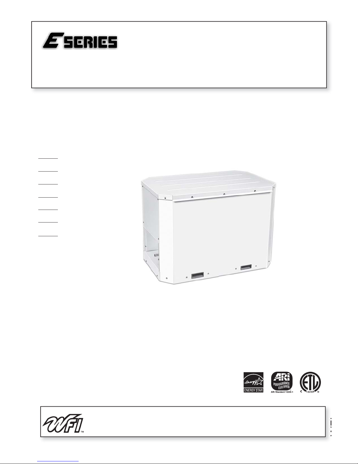
Geothermal/Water Source Split Heat Pumps
• R-410A Refrigerant
• 2, 2.5 Ton Single Speed
• 3, 4, 5, 6 Ton Dual Capacity
Installation Information
Water Piping Connections
Desuperheater Connections
Electrical
Startup Procedures
Troubleshooting
Preventive Maintenance
ES Split Installation Manual
IM1460 11/06
WFI
Page 2
ES SPLIT INSTALLATION MANUAL
Model Nomenclature
Family
ES=ESeriesSplit
Unit Capacity
024 MBTUH 048 MBTUH
030 MBTUH 060 MBTUH
036 MBTUH 072 MBTUH
Control Option
S = Standard Controls
Voltage
1 = 208-230/60/1
Loop Pump Options
A = Standard Loop Connections
ES 036 S 1 A N B SS A
Vintage
A = 024-030
B = 036-072
Non-Standard Option Details
S=Standard
A-R, T-Z Non-standard Options
Sound Kit
A = None
B = Blanket
Coax Options
N = Cupronickel
2
Page 3

ES SPLIT INSTALLATION MANUAL
T able of Contents
General Installation Information 4-5
Water Piping 6-8
Heat Recovery Unit 9
Electrical 10-11
Wiring Schematics 12-13
DIP Switch Settings 14
Refrigeration 15-16
Unit Startup 17
Modes of Operation 18-19
Checking Superheat and Subcooling 20-22
Pressure Drop and Recommended Flow Rates 23
Service 24-25
Pressure/Temperature Conversion Chart 26
Preventive Maintenance 27
Replacement Procedures 27
3
Page 4

ES SPLIT INSTALLATION MANUAL
General Installation Information
Safety Considerations
WARNING: Before performing service or maintenance operations on a system, turn off main power
switches to both units. Turn off accessory heater power switch if applicable. Electrical shock
could cause personal injury. Installing and servicing heating and air conditioning equipment can
be hazardous due to system pressure and electrical components. Only trained and qualifi ed ser-
vice personnel should install, repair or service heating and air conditioning equipment.
Untrained personnel can perform the basic maintenance functions of cleaning coils and cleaning and replacing fi lters. All
other operations should be performed by trained service personnel. When working on heating and air conditioning equipment,
observe precautions in the literature, tags and labels attached to the unit and other safety precautions that may apply.
Follow all safety codes. Wear safety glasses and work gloves. Use a quenching cloth for brazing operations and have a
fi re extinguisher available.
Moving and Storage
Move units in the normal “up” orientation. Do not stack more than three units in total height. When the equipment is
received, all items should be carefully checked against the bill of lading to be sure that all crates and cartons have been
received. Examine units from the cartons if necessary. Units in question should also be internally inspected. If any damage
is noted, the carrier should make the proper notation on the delivery receipt, acknowledging the damage.
General Information
The ES split compressor section is designed for applications that are not feasible with packaged units. Common applications for the ES split are downfl ow, horizontal, attic or crawlspace installations (where there is a need to have water con-
nections and duct work in different locations). Other applications that are easily adapted to the ES split are replacements of
existing air-to-air heat pumps and fossil fuel furnace add-ons.
It is required that the fi nned air coil be installed on the supply side of the fossil fuel furnace to prevent condensation on
the furnace heat exchanger during cooling mode.
The installation of the ES split is similar to packaged units with the addition of refrigeration piping and charging. Refrigerant lines are to be limited to 50 feet in length. The ES split is manufactured with an extended range expansion valve for
proper performance on earth coupled loop installations.
ARI ratings are based upon a matched compressor section and blower coil section for each model number. Other
manufacturers’ blower coils or mismatched sets may not produce similar/desired results. Using coils other than that specifi ed in the ARI matched rating may alter unit performance.
Split Unit Location
Locate the split compressor section away from areas that may disturb the customer and in a way that allows easy re-
moval of the access panels and the top of the cabinet. Provide suffi cient room to make water, electrical and refrigerant line
connections and allow space for service personnel to perform maintenance. When installed indoors the unit should always
be mounted on a vibration absorbing pad or mesh to reduce noise. The ES split is also approved for outdoor installation
when properly installed.
Duct System
In applications using galvanized metal ductwork, a fl exible duct connector is recommended on both the supply and
return air plenums to minimize vibration from the blower. To maximize sound attenuation of the unit blower, the supply and
return plenums should include an internal duct liner of 1-inch thick glass fi ber or be constructed of ductboard. Insulation is
usually not installed in the supply branch ducts. Ducts in unconditioned areas should be wrapped with a minimum of 1-inch
duct insulation. Application of the unit to uninsulated ductwork in an unconditioned space is not recommended as the unit’s
performance will be adversely affected. If the air handler is connected to existing ductwork, a previous check should have
been made to assure that the duct system has the capacity to handle the air required for the unit application.
If ducting is too small, as in the replacement of heating only systems, larger ductwork should be installed, checked for
leaks and repairs made accordingly. The duct system and diffusers should be sized to handle the design airfl ow quietly. If
air noise or excessive airfl ow is a problem, the blower speed can be changed to a lower speed to reduce airfl ow. This will
reduce the performance of the unit slightly in heating; however, it will increase the temperature rise across the air coil.
Airfl ow must still meet minimum requirements.
4
Page 5
ES SPLIT INSTALLATION MANUAL
General Installation Information (cont.)
Condensate Drain
Follow the blower coil manufacturer’s instructions.
Air Handler Installation
Air handlers used with Dual Capacity units must be capable of operating with a minimum of 2 blower speeds. For details on installing the air handling portion of the system, refer to the manufacturer’s instructions for the blower coil unit. All
blower coil units/air coils must be installed as specifi ed by the manufacturer’s instructions. However, the following recom-
mendations should be considered to minimize noise and service problems:
An air fi lter must be installed upstream of the air coil on the return air side of the air handler or furnace. If there is lim-
ited access to the fi lter rack for normal maintenance, it is suggested that a return air fi lter grille be installed. Be sure that the
return duct is properly installed and free of leaks to prevent dirt and debris from bypassing the fi lter and plugging the air coil.
Notes: Improper installation of equipment may result in undesirable noise levels in the living areas.
Ensure that the line set size is appropriate to the capacity of the unit (refer to page 15). Line sets should be routed as
directly as possible, avoiding unnecessary bends or turns. Seal all wall penetrations properly. Line sets should not directly
contact water pipes, fl oor joists, wall studs, duct work, fl oors, walls and brick. Line sets should not be suspended from joists
or studs with a rigid wire or strap which directly contacts the tubing. Wide hanger strips which conform to the shape of the
tubing are recommended. Isolate hanger straps from line set insulation by using metal sleeves bent to conform to the shape
of insulation. Line set insulation should be pliable, and should completely surround the vapor tube.
Compatible Air Handlers
ES MODEL
MATCHING VARIABLE SPEED
AIR HANDLER
ES024 FV4ANF003 (3 TON)
ES030 FV4ANF003 (3 TON)
ES036 FV4ANF003 (3 TON)
ES036 FV4ANF005 (4 TON)
ES048 FV4ANF005 (4 TON)
ES048 FV4ANF006 (5 TON)
ES060 FV4ANF005 (4 TON)
ES060 FV4ANF006 (5 TON)
ES072 FV4ANF006 (5 TON)
Notes: Matching equipment model numbers are
®
Carrier
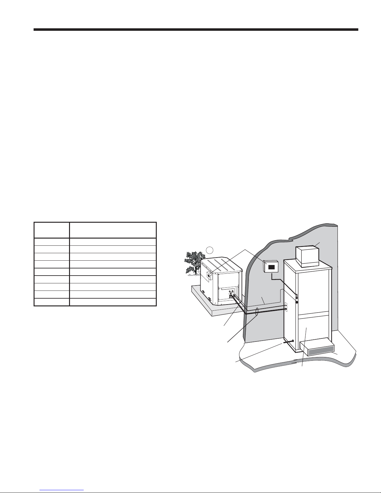
Figure 1: Typical Split System Application - Remote Blower Coil
with Electric Auxiliary Heat
Supply
Duct
Air
Handler
Return
Duct
Insulated
Suction Line
Lineset
To Air Handler
Condensate Drain
(must be trapped)
Disconnect
Low
Voltage Wire
Remote Air Handler
(Maximum Recommended Distance is
50' Between Units)
5
Page 6
ES SPLIT INSTALLATION MANUAL
Water Piping
Residential ES split units are supplied standard with brass water connections which will connect to optional internal loop
pump(s) or 3-way valves. The 3-way valves can be adapted to threaded, barb, or fusion fi ttings. Flush and fi ll adapters are
available separately.
ES units are supplied standard with pressure/temperature taps for checking pressure drop and fl ow rates.
CAUTION: Never use fl exible hoses smaller than 1-inch inside diameter on the unit and limit
hose length to 10 feet per connection. Check carefully for water leaks.
CAUTION: Water piping exposed to outside temperatures may be subject to freezing.
Closed Loop - Earth Coupled Systems (Indoor Installations)
Once piping is completed between the unit, the fl ow center and the earth loop, fi nal purging and charging of the loop is
needed. A fl ush cart (at least a 1.5 HP pump) is needed to achieve adequate fl ow velocity in the loop to purge air and dirt
particles from the loop itself. An antifreeze solution is used in most areas to prevent freezing. Maintain the pH in the 7.6 to
8.2 range for fi nal charging. Flush the system adequately to remove as much air as possible. Pressurize the loop to a static
pressure of 40 to 60 psi. This is normally adequate for good system operation. Ensure that the circulating system provides
adequate fl ow through the unit by checking pressure drop across the heat exchanger and comparing it to the fi gures shown
in the table on page 23.
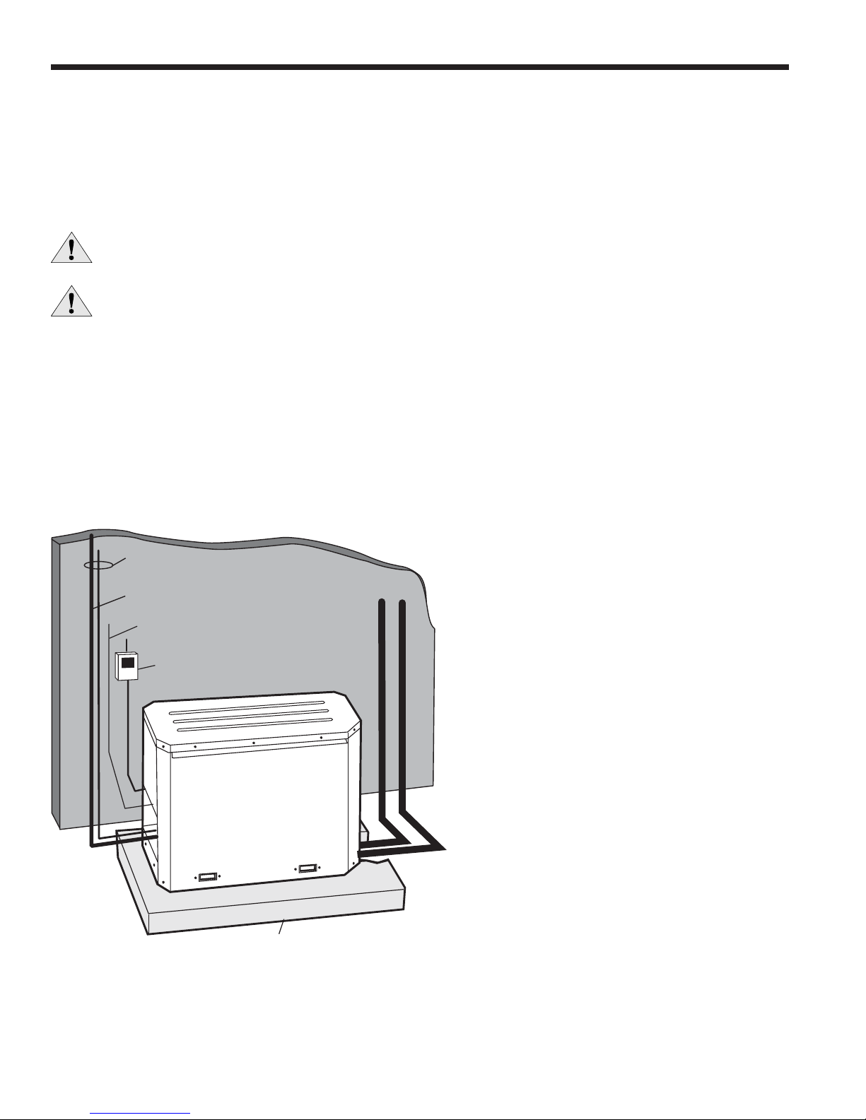
Figure 2: Indoor Installation Using Closed Loop
Line set
To Air Handler
Insulated
Thermostat Wire
From Air Handler
Disconnect
To Loop
VibrationAbsorbing Pad or Air Pad
with access hole for piping entry
6
Page 7
ES SPLIT INSTALLATION MANUAL
Water Piping (cont.)
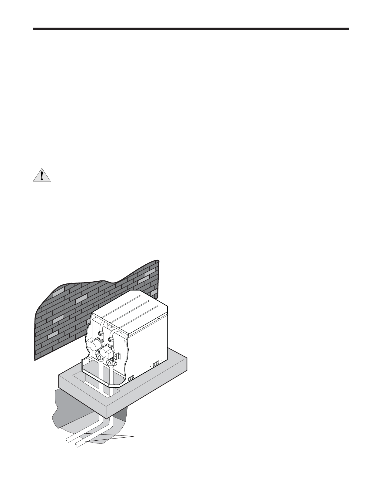
Closed Loop - Earth coupled Systems (Outdoor Installations)
Locate unit on an air pad with access hole as shown below. When mounting on an existing concrete pad, holes must
be bored through to accommodate 1 1/4-inch P.E. pipe with 1/2-inch insulation.
Loop Circulator
The optional fi eld installed, circulating pump(s) and 3-way valve assemblies should be used for outdoor installations.
Wiring connections are supplied in the rear compartment of the unit.
Connecting To Earth Loop
The earth loop trench should be continued directly under the unit as shown in Figure 3. Make the connections to optional fi ttings from the loop circulator pump(s) and insure proper backfi ll to support the loop pipe during trench settling. All 1
1/4-inch piping should be insulated with a minimum of 1/2-inch closed cell insulation from below the ground surface to the
loop circulator.
IMPORTANT
circulator pump if loop temperature drops below 20°F. Loop freeze protection should also be maintained
to the lowest temperature the insulated loop may encounter in the case of power failure.
- A freeze protection thermostat is installed in the unit to automatically start loop
Closed Loop Valve and Pump Kits
Two kits are available when installing pumps inside the unit. The ES-VPK1 contains one pump and fl ush/fi ll valves. The
ES-VPK2 contains two pumps and fl ush/fi ll valves. To determine whether one or two pumps are required, do pressure drop
calculation. Refer to installation instructions for valve/pump kits included in the kit.
Notes: Typically 3 GPM of fl ow per ton of cooling capacity is recommended in earth loop applications.
Figure 3: Typical Split System Outdoor Installation Using Closed
Loop
Loop Supply
and Return
Piping
7
Page 8
ES SPLIT INSTALLATION MANUAL
Water Piping (cont.)
Open Loop - Well Water Systems
CAUTION: Although the unit is approved for outdoor installations, the use of this product is
prohibited in open loop applications unless installed indoors.
Open Loop Applications
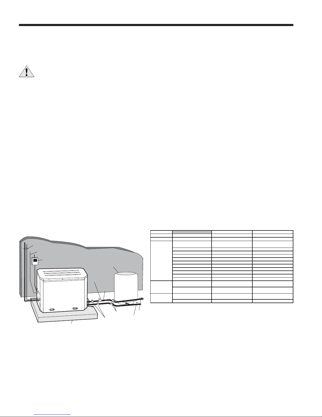
To provide a copper sweat connection for water line piping, remove the brass connectors from the unit. This can be
done with a tube cutter or torch. Be careful to keep debris and contamination out of the water lines. Clean the connections and pipe to the water source using standard plumbing practices. Reference well water piping kit instructions for the
WWK2T, WWK3T as needed. Typical open loop piping is shown below. Always maintain water pressure in the heat exchanger by placing a water control valve at the outlet of the unit and use a closed bladder pressure tank to minimize mineral
deposits. Ensure proper water fl ow through the unit by checking pressure drop across the heat exchanger and comparing it
to the fi gures in the table on page 23.
Water control valves draw their power directly from a unit’s 24V transformer and can overload and possibly burn out the
transformer. Check total VA draw of the water valve and ensure that it is under 15 VA.
Notes: Normally, about a 2 GPM fl ow rate per ton (1.5 GPM/ton minimum for EWT > 50°F) of cooling capacity is needed in
open loop systems.
Discharge water from the unit is not contaminated in any manner and can be disposed of in various ways depending on
local building codes (i.e. recharge well, storm sewer, drain fi eld, adjacent stream or pond, etc.). Most local codes forbid use
of sanitary sewer for disposal. Consult your local building and zoning department to assure compliance in your area.
Water Quality
In applications where the water quality cannot be held to prescribed limits, the use of a secondary or intermediate heat
exchanger is recommended to separate the unit from the contaminated water. The following table outlines the water quality
guidelines for unit heat exchangers. If these conditions are exceeded, a secondary heat exchanger is recommended.
Figure 4: Typical Split System Indoor
Installation Using Well Water
Line set
ToAir Handler
Thermostat Wire
From Air Handler
Disconnect
Water Solenoid
Control Valve
Regulator
Boiler Drains for
VibrationAbsorbing Pad or Air Pad
with access hole for piping entry
System Flushing
Rubber Bladder
Pressure Tank
Flow
Shut-Off Valves
Water In
From Well
Water Quality Guidelines
Material Copper 90/10 Cupro-Nickel
pH Acidity/Alkalinity 7- 9 5 - 9
Scaling Calcium and Magnesium Carbonate (Total Hardness) less than 350 ppm (Total Hardness) less than 350 ppm
Corrosion
Iron Fouling
(Biological Growth)
Erosion
Note: Grains = PPM divided by 17 • mg/l is equivalent to PPM
Water
Out
Hydrogen Sulfide
Sulfates Less than 125 ppm Less than 125 ppm
Chlorine Less than .5 ppm Less than .5 ppm
Chlorides Less than 20 ppm Less than125 ppm
Carbon Dioxide Less than 50 ppm 10 - 50 ppm
Ammonia Less than 2 ppm Less than 2 ppm
Ammonia Chloride Less than .5 ppm Less than .5 ppm
Ammonia Nitrate Less than .5 ppm Less than .5 ppm
Ammonia Hydroxide Less than .5 ppm Less than .5 ppm
Ammonia Sulfate Less than .5 ppm Less than .5 ppm
Total Dissolved Solids (TDS) Less than 1000 ppm 1000-1500 ppm
Iron, Fe2+ (Ferrous)
Bacterial Iron Potential
Iron Oxide
Suspended Solids
Threshold Velocity (Fresh Water) 5-8 ft/sec 8-12 ft/sec
Less than .5 ppm
(rotten egg smell appears at 0.5 PPM)
None None
Less than 1 ppm. Above this level
deposition will occur.
Less than 10 ppm and filtered for max
of 600 micron size
10 - 50 ppm
Less than 1 ppm. Above this level
deposition will occur.
Less than 10 ppm and filtered for max
of 600 micron size
8
Page 9
ES SPLIT INSTALLATION MANUAL
Heat Recovery Unit for Domestic Hot Water
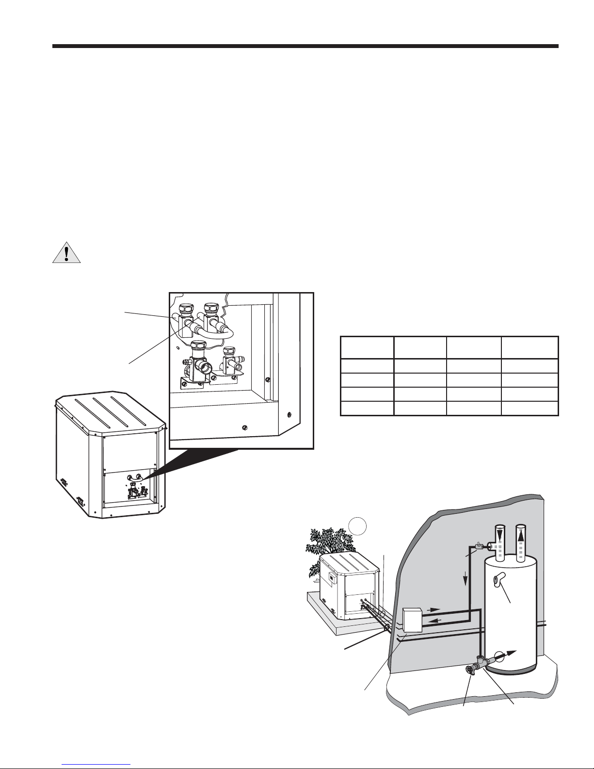
Service valves have been provided inside the unit for connecting the discharge gas line to a water heating heat recov-
ery unit (see fi gure 5). To make the connections, close the service valves inside the unit by turning clockwise. Using a
recovery canister connect to either of the schrader ports on the DSH service valves and recover the small amount of refrigerant trapped inside of the U-tube. Prior to brazing ensure that all refrigerant has been removed from U-tube. Once
the refrigerant is removed, it is recommended that the tube be cut at the “U” to remove any excess oil that may be trapped.
(This will also allow for easier removal of the tubing with a torch, since each section can be removed independently). Ser-
vice valves must be protected to prevent overheating. Unbraze the 1/2-inch O.D. U-tube and run tubing from the left
hand service valve to the inlet of the heat recovery unit and from the outlet of the heat recovery unit to the right hand of the
service valve. Typically the one way discharge line length should be limited to 25-30 feet and line size must be increased
depending on unit size and length of run. Follow the instructions supplied with the heat recovery unit for mounting location,
water piping, and start up. A typical installation is shown below.
IMPORTANT - Reopen discharge line service valves before starting up unit, but only after leak checking,
purging, and evacuating new discharge line.
Figure 5: Service Valves for Heat Recovery Unit Connections
To
Compressor
Heat Recovery
Unit “In”
Maximum One-Way Line Length
From
Heat Recovery
Unit “Out” to
Reversing
Valve
SIZE 1/2” OD 5/8” OD 3/4” OD
024 - 036 Up to 9 ft. Up to 25 ft. Up to 30 ft.
048 Up to 5 ft. Up to 13 ft. Up to 30 ft.
060 N/A Up to 9 ft. Up to 25 ft.
072 N/A Up to 6 ft. Up to 20 ft.
Figure 6: Typical Hot Water Piping Layout
Line set
To Hot Water
Generator
Venting
Waste Valve or
Vent Coupling
Cold
Hot
P/T Relief
Valve
Insulated Line set
With UV Paint
To Air handler
Add-on
Hot Water
Generator with
Internal Pump
9
Drain Valve
Pipe Tee
Page 10
ES SPLIT INSTALLATION MANUAL
Electrical
General
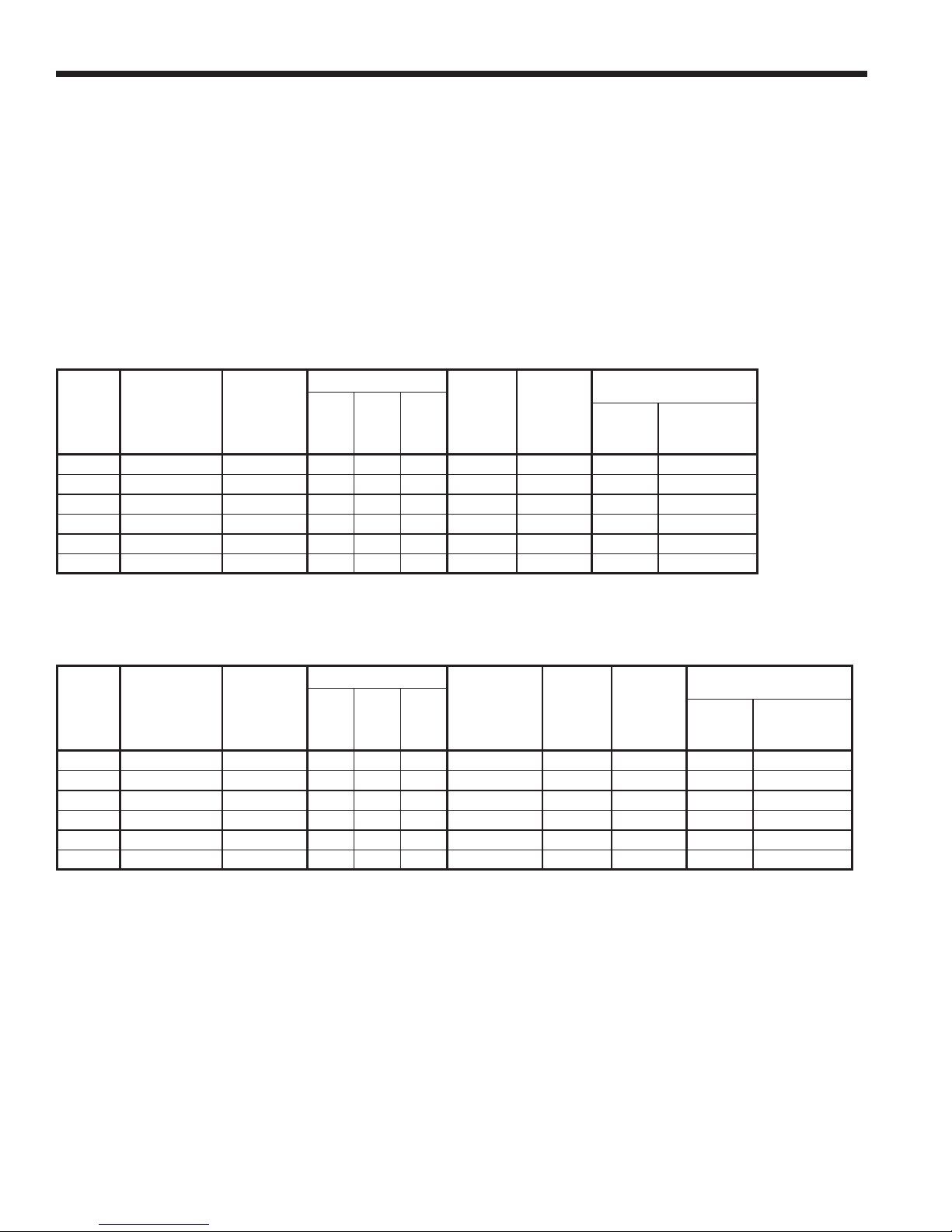
Be sure that the available power is the same voltage and phase as shown on the unit serial plate. Line and low volt-
age wiring must be done in accordance with local codes or the National Electric Code, whichever is applicable. See tables
below for fuse or circuit breaker sizing information. Refer to the wiring schematic inside the unit access panel for more
information.
Accessory Pump Operation
Refer to the wiring diagram on the unit’s wiring schematic for instruction on wiring the pumps to the unit.
Electrical Data Without Loop Pump(s)
COMPRESSOR
MODEL
ES024 208-230/60/1 197/253 13.0 8.3 48.0 8.3 10.4 15 15
ES030 208-230/60/1 197/253 15.5 9.9 55.0 9.9 12.4 20 20
ES036 208-230/60/1 197/253 19.5 12.5 66.0 12.5 15.6 25 25
ES048 208-230/60/1 197/253 28.0 17.9 96.0 17.9 22.4 40 40
ES060 208-230/60/1 197/253 38.5 24.7 130.0 24.7 30.9 50 50
ES072 208-230/60/1 197/253 41.0 26.3 130.0 26.3 32.9 50 50
Notes: Always refer to unit nameplate data prior to installation. ACR circuit breaker in United States only. All
fuses are class RK-5.
RATED
VOLTAGE
VOLTAGE
MIN./MAX.
MCC RLA LRA
TOTAL
UNIT
FLA
MIN.
CIRCUIT
AMP.
RESIDENTIAL
MAX
FUSE
MAX. HACR
BRAKER
Electrical Data With Loop Pump(s)
COMPRESSOR
MODEL
ES024 208-230/60/1 197/253 13.0 8.3 48.0 1.8 10.1 12.2 20 20
ES030 208-230/60/1 197/253 15.5 9.9 55.0 1.8 11.7 14.2 20 20
ES036 208-230/60/1 197/253 19.5 12.5 66.0 1.8 14.3 17.4 25 25
ES048 208-230/60/1 197/253 28.0 17.9 96.0 1.8 19.7 24.1 40 40
ES060 208-230/60/1 197/253 38.5 24.7 130.0 3.5 28.2 34.1 50 50
ES072 208-230/60/1 197/253 41.0 26.3 130.0 3.5 29.8 36.4 60 60
Notes: Always refer to unit nameplate data prior to installation. HACR circuit breaker in United States only. All fuses are class
RK-5.
RATED
VOLTAGE
VOLTAGE
MIN./MAX.
MCC RLA LRA
INTERNAL
LOOP PUMP
FLA
TOTAL
UNIT
FLA
MIN.
CIRCUIT
AMP.
RESIDENTIAL
MAX
FUSE
MAX. HACR
BRAKER
10
Page 11
ES SPLIT INSTALLATION MANUAL
Electrical ( c on t.)
Dual Fuel Systems
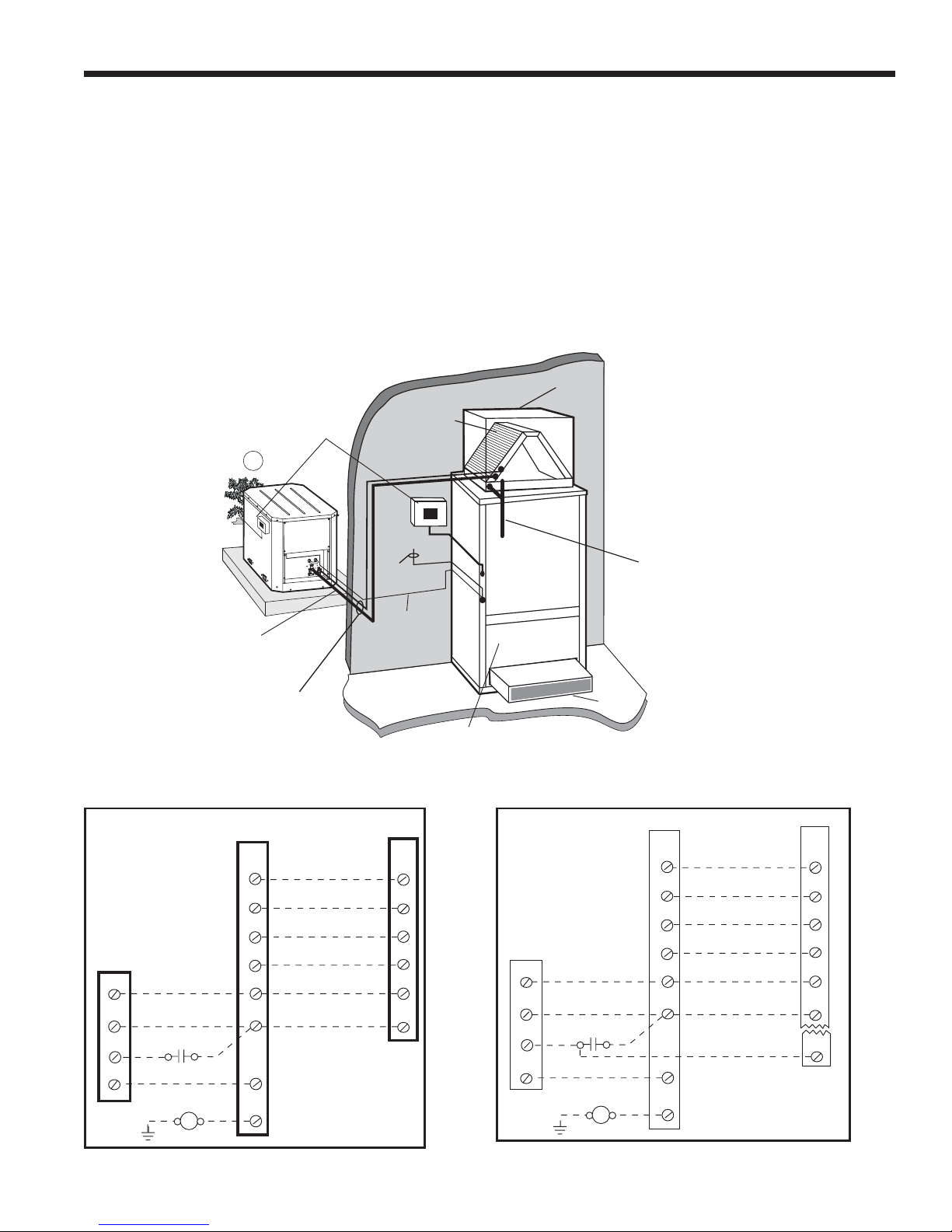
ES units can be connected to fossil fuel furnaces that include an A-coil or slab coil. Dual fuel installations utilize the
ES heat pump for heating until the point that auxiliary heat is called for on the thermostat. At that point, the furnace will be
enabled and the heat pump will be disabled. The ES heat pump provides air conditioning through the furnace’s refrigerant
coils.
Refer to the furnace manufacturer’s installation manual for the furnace installation, wiring and coil insertion. A fi eld-in-
stalled SPDT auxiliary heat relay is required. See Figure 7 for typical Dual Fuel application. Figure 8 shows the wiring for
Single Speed ES units. Figure 9 shows wiring for Dual Capacity ES units.
Figure 7: Typical Split System Application - Heat Pump Coil Add-On Fossil Fuel Furnace
Supply
Duct
Disconnect
"A" or
Slab Coil
-Flow
Up
Fossil Fuel
Insulated Suction
Line
Lineset
ToAir Handler
Wire To
Thermostat
Low
Voltage Wire
Remote Air Handler
(Maximum Recommended Distance is
50' Between Units)
Furnace
Condensate
Drain
(must be trapped)
Return
Duct
Figure 8: Single Speed Dual Fuel Wiring Figure 9: Dual Capacity Dual Fuel Wiring
Thermostat
Y1
1st Stage Compressor
Y2
2nd Stage Compressor
O
Reversing Valve
L
C
R
G
W
Fault Signal
Common
24 VA
Emergency Shutdown
Note: Field installed SPST dual fuel relay
(Required for dual fuel installation)
C
Fossil Fuel
Furnace
C
R
W
G
Commo n
24 VA C
Auxiliary Heat
Fa n
Auxiliary Heat Relay
Thermostat
Y1
Y2
O
L
C
R
G
W
1st Stage Compressor
2nd Stage Compressor
Reversing Valve
Fault Signal
Commo n
24 VA C
Split
Y1
Y2
O
L0
C
R
Fossil Fuel
Furnace
C
R
W
G
Common
24 VAC
Auxiliary Heat
Fan
Auxiliary Heat Relay
ES Split
P1
Y1
Y2
O
L0
C
R
ES
P2
11
Page 12
ES SPLIT INSTALLATION MANUAL
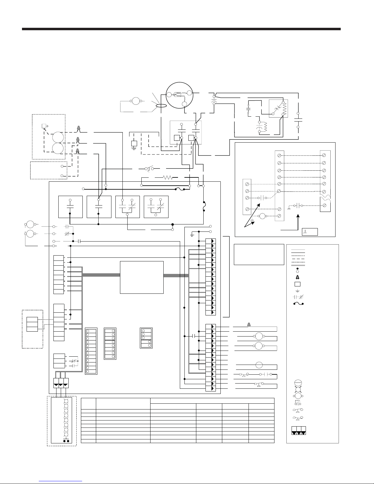
Wiring Schematics
ES Series - Dual Capacity Split Wiring Schematic - 208-230/60/1
97P621-10 10/13/05
BRISTOL DUAL CAPACITY
CCH
Blk
CCL
NOTE 1
SL1 In
SL1 Out
Optional
RemoteUnit
Without
Loop Pump
1/2 HP 208-230/60/1
White
Red
Black
C
LoopPump(s)
G
Heat
Recovery
Unit
FieldDiagnositcsLED Board
Pump
Pump
L2
L1
CR1
CCHI
CCLO
CC-GND
P1
R
C
Y1
Y2
W
O
G
LO
P2
Shut
DownC1
SL1 In
SL1 Out
Not
Used
NOTE 2
P3
Acc Com
Acc NC
Acc NO
123
StatusLED PCB
SW4
Current Switch
Black
CS
Black
Unit Power
Fused L2
NO NC
COM
CR3
Microprocessor
1
Test / Norm
Loop / Well
2
3
Fan / Comp
4
Not Used
5
Not Used
6
Inputs / Norm
7
Outputs / Norm
8
24 VAC / TA32E12
208-230/60/1
G
Blk/
Wht
NO NC
CR4
Black
Logic Control
(DC Voltage)
FP
Red
OnSW3OnSW2
Dual/Single Capacity
1
Must be OFF
2
3
No RPM / RPM
4
Not Used
Must Be ON
5
#1 Off, #6 On, #7 On
Not Used
FP thermistor (loop<15°F, well<30°F)
HighPressure > 600PSI
Low Pressure < 40 PSI
Not Used
NotUsed
Not Used
Not Used
Red
White
Black
Fused L2
NO
COM
CR2
CC
1
2
3
4
5
6
7
8
1
1
2
2
2
3
3C
3
4
5
6
7
1
2
3
P4
R
R
R
R
R
G
Y
R
ECM2
AirFlow
Settings
LED Normal Display Mode
Drain
Water Flow
High Press
Low Press
Air Flow
Status
DHW Limit
DHW off
*GreenLED not flashing
Fused L2
NO
COM
OnSW1
1
2
3
4
5
6
7
8
9
10
NOT USED
11
12
Field Selection Dips -#1 On, #6 On, #7 On
Not Used
FP thermistor (loop<15°F,well<30°F) Lockout
High Pressure > 600PSI Lockout
Low Pressure < 40 PSILockout
Not Used
Microprocessormalfunction*
Not Used
Not Used
Protector
C
Black
L2 L1
Blk/
Wht
Crankcase Heater
F1-10A 240V
COM
Fused L1
Current Fault Status
Main
Red
240V L2
Start
R
Red
CCH
Violet
RUN CAP
Pink
Black
240V L1
F1-10A 240V
P6
8
13
7
4
5
14
12
6
15
10
9
2
1
3
11
16
P5
11
4
9
2
10
3
8
1
12
5
13
6
7
14
Diagnostic Modes
Inputs
#6 Off, #7 On
Y1
Y2
O
Not Used
Not Used
SL1
SL2
2
1
Tan
R
C
Orange
T1
SC
X1
Pink
Pink
START
CAPACITOR
Dual Fuel Wiring Diagram
Fossil Fuel
Furnace
C
R
W
G
Note: Fieldinstalled DPST dual fuel relay
(Requiredfor dual fuel installation)
Notes
1 - Connectionof remote unit thatdoes not have
a loop pump forslave operation.
2 - 24VAccessory relay (see SW2 - 3 for
description of operation)
3 - Fieldinstalled DPST dual fuel relay.
(Requiredfor dual fuelinstallation)
NOT USED
Tan
Tan
Orange
Orange
Brown
Brown
Not Used
Not Used
Yellow
Yellow
LP
Blue
Blue
Black
Black
Outputs
#6 On, #7 Off
Lo Capacity Compressor
Hi Capacity Compressor
RV
FAN
Not Used
Loop Pump 1
Loop Pump 2
Tan
1
2
24 VAC
Auxiliary Heat R elay
Fan
Auxiliary Heat Relay
T
CS
Outputs2
#6 Off, #7 Off
Not Used
Not Used
Not Used
Not Used
Not Used
Not Used
Not Used
Not UsedNot UsedNot Used
Y1
O
L
C
R
5
2
CCL
1st Stage Compressor
2nd Stage Compressor
Pink
T1
X1
Tan
Reversing Valve
Fault Signal
24 VAC
Auxiliary
Heat Relay
nommoCnommoC
=chassis
ES Split
Shut
Down
Y1
Y2
O
P1
LO
C
R
P2
SR
1
Pink
Thermostat
Y2
G
W
Legend
Factory Low voltagewiring
Factory Line voltage wiring
Fieldlow voltage wiring
Fieldline voltage wiring
Optionalblock
DC Voltage PCB traces
Internal junction
Quick connect terminal
Wirenut
Fieldwire lug
L1
Ground
RelayContacts-
N.O., N.C.
Fuse
T
G
132
CurrentSwitch
Compressor Contactor
Not Used
Loop pump relay 1
Loop Pump relay 2
Not Used
Fuses
Freeze protection sensor
High pressure switch
Low pressure switch
Power strip
Reversing Valve coil
Not Used
DIP package 8 position
DIP package 5 position
Not Used
Thermistor
Light emitting diode -Green
Relaycoil
Capacitor w/ bleed resistor
Switch - High pressure
Switch - Low pressure
Polarized connector
CS CC CR1 CR2CR3 CR4 F1 and F2 FP -
RV
HP LP PS -
SC
RV SW1 SW2 SW3 SW4 -
FP
HP
P
Blue
S
12
Page 13
ES SPLIT INSTALLATION MANUAL
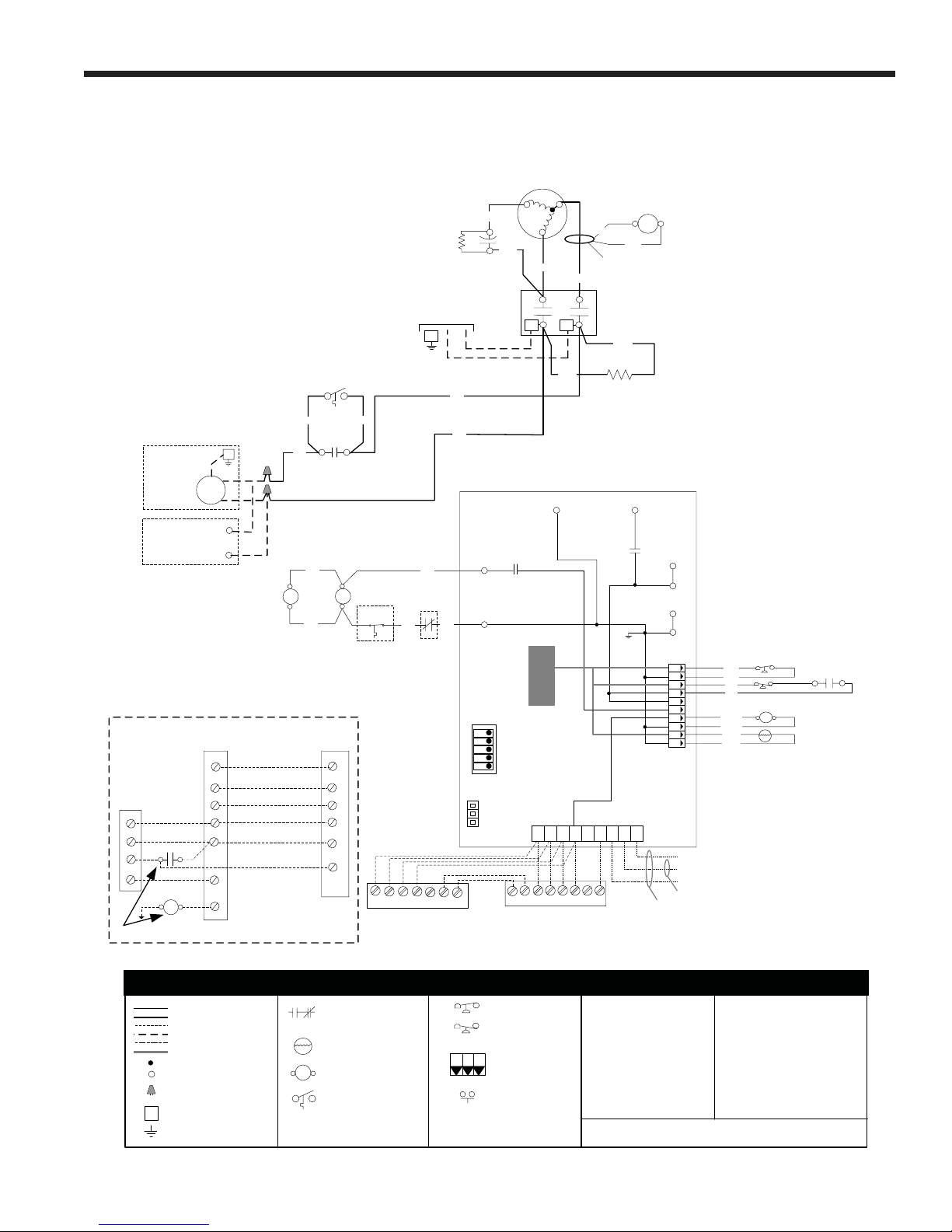
Wiring Schematics (cont.)
ES Single Capacity Series - Wiring Schematic - 208-230/60/1
97P621-11 06/22/04
Power Supply
208-230/60/1
G
PTCR
Unit
Compresso
r
Blue
Cap
Violet
S
R
Red
T2 T1
C
Black
Blk
CC
L1L2
CS
Black
Current Switch
Orange
LoopPump
1/2 HP 208-230/60/1
Heat
Recovery
Unit
Fossil Fuel Furnace Connection
Thermostat
Fossil
Fuel
Furnace
C
Common
R
24 VAC
Auxillary Heat
W
G
Fan
Auxillary Heat Relay
Note 4: Field Installed SPST daul fuel relay.
G
Pump
L1
L2
Y1
O
L
C
R
G
W
Black
PR
1st Stage Compressor
Reversing Valve
Fault Signal
Common
24 VAC
Blk/Wht
Violet
Violet
NO
Premie
Split
FP
Blk/Wht
PR
Com
CCL
Note 5
Outdoor Air
Temperature
Violet
rE
Y1
O
LO
C
R
ES
Air handler
24 VAC
Common
Black
White
Violet
CC
CCG
SW1
Off
1
2
3
4
5
On
Test / Normal
Loop / Well
Commercial/ Normal
Not Used/ E Split
Not Used/ Single Cap Split
Violet
Note4
P3
G
O
Y1
W/W1
Orange
CPu
Thermostat
G
24 VAC
Common
Crankcase
Heater
R
R
C
C
P2
1
6
2
7
8
3
4
9
5
10
P1
Note 6
G/Y2
OYCR
Y1
RV
LSNSESLO
Loadshed
Night Setback
Emergency Shutdown
NOTE 2
NOTE 1
Black
Black
Blue
Blue
Orange
Orange
Yellow
Yellow
HP
LP
T
CS
RV
FP
Lockout
Emergency Heat
Factory low voltage wiring
Factory line voltage wiring
Field low voltage wiring
Field line voltage wiring
Optional block
DC voltage PCBtraces
Internaljunction
T
Quick connect terminal
Wire nut
L1
Field wire lug
Ground
Relay ContactsN.O., N.C.
Thermistor
Relay coil
Loop Freeze Protection Switch
P
2
3
Legend
Switch- High pressure
Switch- Low pressure
1
Polarized connector
CondensateOverflow
13
CC -
Compressorcontactor
CO -
Condensate overflow
FP -
Freeze protection sensor
HP -
High pressure switch
LP -
Low pressure switch
RB -
Blower power relay
RV -
Reversing Valve coil
SW1 -
DIP switch #1
LPR - Single capacity loop pump relay
PTCR -
Positive Temperature Coefficient
Resistor
CS -
Current Switch
1 - Requires common connection or24 VAC for
activation.
2 - Night setback used only with TA32U02
thermostat.
3 - Switch transformer switchfor 208Voperation.
4 - Field installedDPDT auxiliaryheat relay.
(Required for dual fuel installation)
5 - Field installedoutdoor thermostat(optional).
6 - This terminalis notused in the split
application.
Notes:
Page 14
ES SPLIT INSTALLATION MANUAL
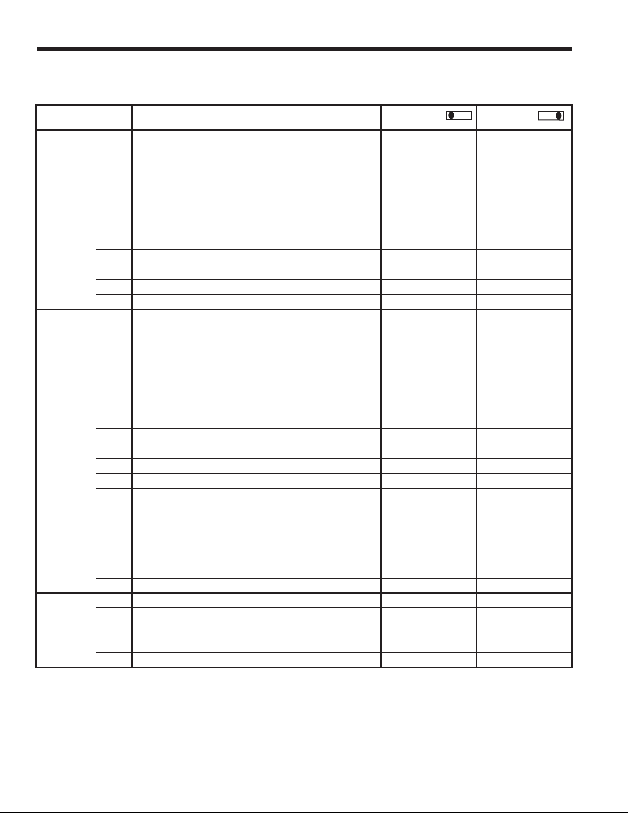
DIP Switch Settings
DIP SWITCH
NUMBER
Service / Test Mode. Allows control of “normal” or “test” Test Mode Normal Timing
operational modes. Test mode accelerates most timing Operation
1 functions 16 times to allow faster troubleshooting. Test
SW1- mode allows viewing the “current” status of the fault
(Single inputs on the LED.
speed Freeze Protection Setting. Allows selection of freeze Loop Water Well Water
units only*) 2 thermistor fault sensing temperatures for well water or Freeze Protection Freeze Protection
antifreeze- protected earth loops. 15º F 30º F
3 Application Selection. Commercial w/ Night Setback Commercial, Night Normal Residential
using TA32U02 thermostat or “Normal” Residential. Setback w/TA32U02
4Split Operation N/ASplit
5Not Used N/AN/A
Service / Test Mode. Allows control of “normal” or “test” Test Mode Normal Timing
operational modes. Test mode accelerates most timing Operation
1 functions 16 times to allow faster troubleshooting. Test
mode allows viewing the “current” status of the fault
Freeze Protection Setting. Allows selection of freeze Loop Water Well Water
2 thermistor fault sensing temperatures for well water or Freeze Protection Freeze Protection
SW2- antifreeze- protected earth loops. 15º F 30º F
(Dual 3 Accessory Relay. Allows selection of the accessory Accessory tracks Accessory tracks
capacity relay to operate with either the compressor or fan. Fan Compressor
units only) 4Not Used N/AN/A
5Not Used N/AN/A
Diagnostics-Inputs. Allows viewing the inputs from the Diagnostic Normal display
6 control board such as the compressor, reversing valve, Inputs viewed viewed at LED
blower, hot water pump, and loop pump on the LED. at LED
Diagnostics-Outputs. Allows viewing the outputs from the Diagnostic Normal display
7 control board such as the compressor, reversing valve, Outputs viewed viewed at LED
blower, hot water pump, and loop pump on the LED. at LED
8 Thermostat selection 24VAC Thermostat N/A
SW3- 1 Dual Capacity Operation Dual Capacity N/A
(Dual 2Not Used N/AN/A
capacity 3 Split Operation Split N/A
units only) 4Not Used N/AN/A
5Not Used N/AN/A
DESCRIPTION
inputs on the LED.
OFF
POSITION
ON
POSITION
Notes: * Although Dual Capacity units have SW1 switches, they are not used.
14
Page 15
ES SPLIT INSTALLATION MANUAL
Refrigeration
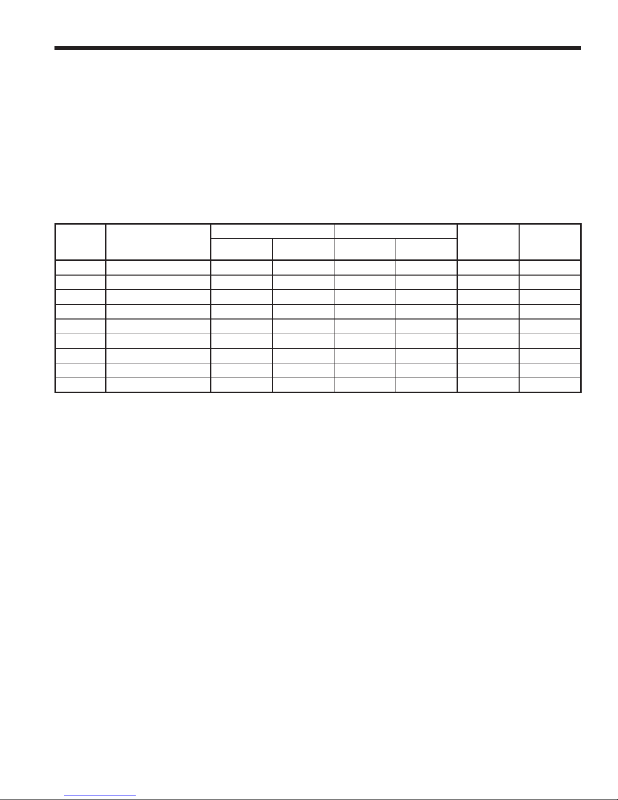
The ES split compressor section contains an adequate charge amount for the compressor section and matching nomi-
nal size air handler. See table below for additional charge amount needed for line set and larger or smaller air handler.
Refrigeration piping on the split consists of installing a brazed copper line set between the blower coil unit and the unit’s
split compressor section. To select the proper tube diameters for the installation, refer to the table below. Line sets over 50
feet long are not recommended because of oil return and pressure drop problems. The suction line must always be insulated. Handle and route the line sets carefully to avoid kinking or bending the tubes. If the line set is kinked or distorted and it
cannot be formed back into its original shape, the bad portion of the pipe should be replaced. A restricted line set will affect
the performance of the system.
Line Set Size and Charge Amount
25’ 50’
SIZE AIR HANDLER
ES024 FV4ANF003 (3 TON) 5/8” OD 3/8” OD 5/8” OD 3/8” OD 84 oz. 84 oz.
ES030 FV4ANF003 (3 TON) 5/8” OD 3/8” OD 5/8” OD 3/8” OD 86 oz. 86 oz.
ES036 FV4ANF003 (3 TON) 3/4” OD 3/8” OD 3/4” OD 3/8” OD 90 oz. 90 oz.
ES036 FV4ANF005 (4 TON) 3/4” OD 3/8” OD 3/4” OD 3/8” OD 90 oz. 104 oz.
ES048 FV4ANF005 (4 TON) 3/4” OD 3/8” OD 3/4” OD 3/8” OD 116 oz. 116 oz.
ES048 FV4ANF006 (5 TON) 3/4” OD 3/8” OD 3/4” OD 3/8” OD 116 oz. 116 oz.
ES060 FV4ANF005 (4 TON) 7/8” OD 3/8” OD 7/8” OD 3/8” OD 148 oz. 150 oz.
ES060 FV4ANF006 (5 TON) 7/8” OD 3/8” OD 7/8” OD 3/8” OD 148 oz. 148 oz.
ES072 FV4ANF006 (5 TON) 7/8” OD 3/8” OD 7/8” OD 3/8” OD 140 oz. 140 oz.
SUCTION LIQUID SUCTION LIQUID
FACTORY
CHARGE
TOTAL
CHARGE
NEEDED
Notes: Line set installations longer than 50’ are not recommended.
* Total charge needed is for air handler and 25 feet of line set. Add 0.5 oz. for each additional foot of line set
Connecting Air Coil
Fasten the copper line set to the blower coil unit as instructed by the coil installation instructions. Install bifl ow fi lter/drier
in liquid line between split unit and air handler. Nitrogen should be bled through the system at 2 to 3 psi to prevent oxidation
inside the refrigerant tubing. Use a low silver phos-copper braze alloy on all brazed connections.
Notes: The air coil should be thoroughly washed with a fi lming agent (automatic dishwashing detergent) to help condensate
drainage. Apply a 20-to -1 solution of detergent and water and spray both sides of coil. Repeat and rinse thoroughly with
water.
Connecting Split Unit
Braze line set to the service valve stubs on the front of the split cabinet. Nitrogen should be bled through the system
at 2 to 3 psi to prevent oxidation contamination. Use a low silver phos-copper braze alloy on all brazed connections. ES
split units are shipped with a factory charge and service valves are not to be opened until the line set has been leak tested,
purged and evacuated. Schrader cores should be removed before brazing. A heat sink should be used on the service
valves to prevent damage caused by excessive heat.
15
Page 16
ES SPLIT INSTALLATION MANUAL
Refrigeration (cont.)
Leak Testing
The refrigeration line set must be pressurized and checked for leaks
before purging and charging the unit. To pressurize the line set, attach
refrigerant gauges to the service ports and add an inert gas (nitrogen or
dry carbon dioxide) until pressure reaches 60 to 90 PSIG. Never use
oxygen or acetylene to pressure test. Use an electronic leak detector or
a good quality bubble solution to detect leaks on all connections made in
the fi eld. Check the service valve ports and stem for leaks and all connec-
tions made in the fi eld. If a leak is found, repair it and repeat the above
steps. For safety reasons do not pressurize the system above 150
psi. Purge pressure from line set. The system is now ready for evacuating and charging.
System Evacuation
Ensure that the line set and air coil are evacuated before opening ser-
vice valves to the split unit. The line set must be evacuated to at least 200
microns to remove moisture and air that may still be in the line set and coil.
Evacuate the system through both service ports to prevent false readings
on the gauge because of pressure drop through service ports.
Charging the System
Total Charging Method - See table on page 15 for the factory charge
and total charge of the split units. For line sets, add the specifi ed refriger-
ant to the factory charge for every installed foot of liquid line over 25 feet.
Example: Model ES048 with 29 feet of installed liquid line (3/8-inch
O.D.). The factory charge of an ES048 is 116 oz. plus 4 feet of liquid line x
0.50 oz. per ft. = 2.0 oz. + 116 oz. = 118.0 oz. (Total Charge). The ES048
is shipped from the factory with 116 oz. of refrigerant; the amount to be
added is 118.0 oz. - 116 oz. = 2.0 oz.
Add the required refrigerant so that the total charge calculated for
the unit and line set is now in the system. Fully open the service valves
by turning counterclockwise. Start the unit in heating mode and measure
superheat and subcooling values after at least fi ve minutes of run time.
See page 20 for examples of measuring superheat and subcooling performance values. After values are measured, compare to tables on pages 21
and 22 and go to FINAL EVALUATION.
Partial Charge Method - After purging and evacuating the line set,
fully open the service valves counterclockwise. Add R-410A (liquid) into
the liquid line service port until the pressure in the system reaches approximately 200 PSIG. Never add liquid refrigerant into the suction side
of a compressor. Start the unit and measure superheat and subcooling.
Keep adding refrigerant until the unit meets the superheat and subcooling
values on pages 21 and 22.
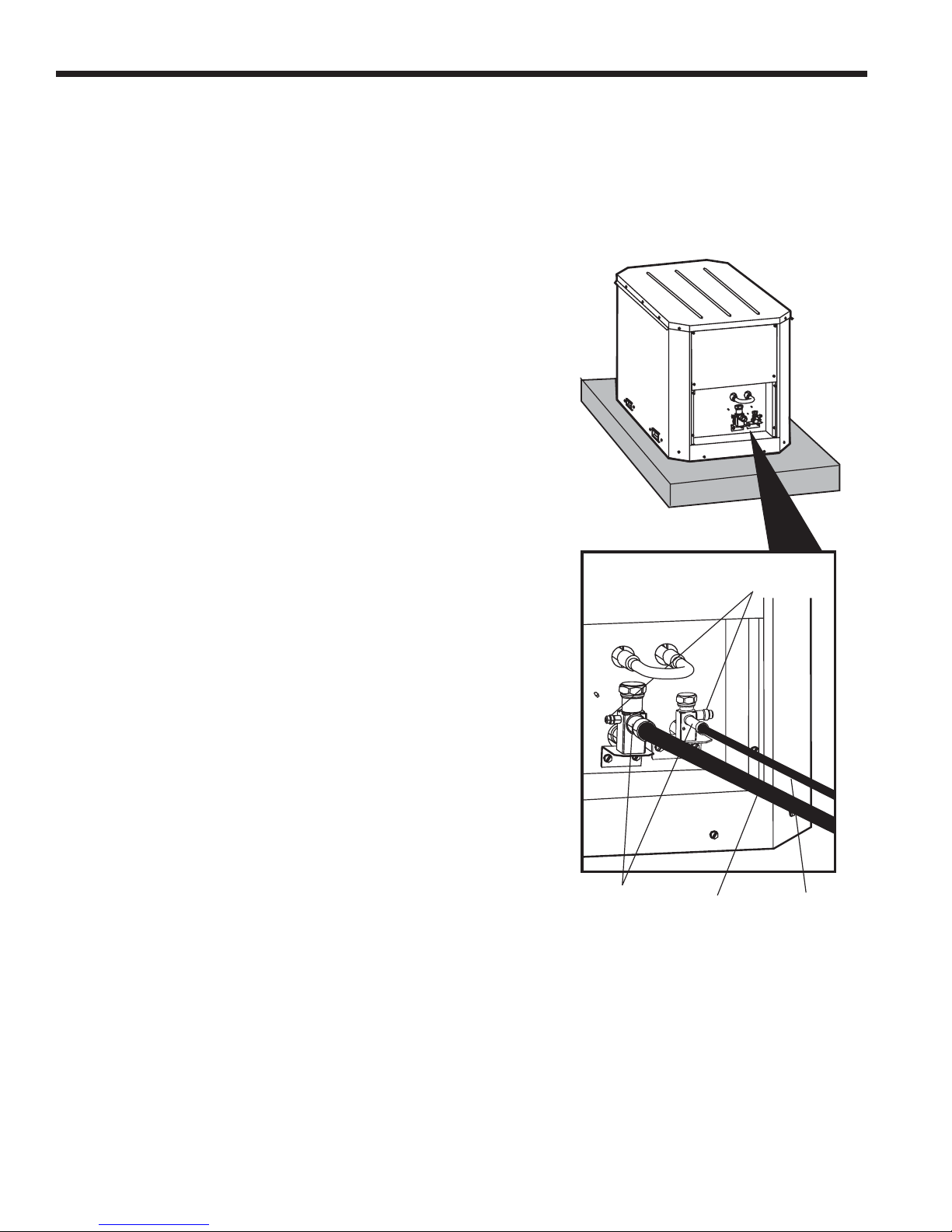
Figure 10: Typical Split System Refrigerant
Line Connections
Replace caps after
adjusting service valves
Service ports for attaching
refrigerant gauges
Braze
Connections
Suction Line Liquid Line
Final Evaluation
After the initial check of superheat/subcooling values in the heating mode, shut off the unit and allow it to sit 3 to 5 min-
utes until pressures equalize. Restart the unit in the cooling mode and check the values against those in tables on pages
21 and 22. If the unit performs satisfactorily, charging is complete. If the unit does not perform to specifi cations, the charge
may need to be readjusted until the values are close. Adding refrigerant will increase subcooling. Recovering some of the
refrigerant will decrease subcooling and increase superheat. If the superheat/subcooling values are still not close to the
specifi cations in tables on pages 21 and 22, analyze refrigerant circuit operation.
16
Page 17

Unit Startup
Before Powering Unit, Check The Following:
High voltage is correct and matches nameplate.
•
Fuses, breakers and wire size correct.
•
Low voltage wiring complete.
•
Piping completed and water system cleaned and fl ushed.
•
Air is purged from closed loop system.
•
Isolation valves are open, water control valves or loop pumps wired.
•
Condensate line is open, trapped, and correctly pitched (blower coil unit).
•
Blower rotates freely (blower coil unit).
•
Blower speed is correct (blower coil unit).
•
Air fi lter is clean and in position (blower coil unit).
•
Service/access panels are in place.
•
Thermostat is in the “off” position.
•
Return air temperature is between 65°F and 80°F in heating and 70° to 95°F in cooling.
•
Service valves are open.
•
Startup Steps
ES SPLIT INSTALLATION MANUAL
Notes: Starting the compressor without a minimum of 1-2 hours of crankcase heat prior to initial startup may result in
compressor chattering and possible damage to the compressor.
The unit is equipped with a crankcase heater which operates when the compressor is OFF. Energize crankcase heater
1.
24 hours before starting unit. To energize heater only, set indoor thermostat to OFF position and close power disconnect to unit.
Turn thermostat fan to the “ON” position. Blower should operate.
2.
Balance airfl ow at registers and adjust fan speed if necessary.
3.
Set thermostat to highest temperature.
4.
Set thermostat operation switch to “COOL” position. Compressor should NOT come on.
5.
Slowly reduce the thermostat setting until both the compressor and water control valve or loop pumps are activated.
6.
Verify that the compressor is on and that the water fl ow rate is correct by measuring pressure drop through the heat
exchanger (using the P/T plugs and comparing to table on page 23).
Check the temperature of both the supply and discharge water (see tables on pages 21 - 22).
7.
If temperature rise is within range of tables on page 21-22 proceed to step 9. Otherwise check the cooling refrigerant
8.
pressures and compare to tables on pages 21-22.
Check for air temperature drop of 16°F to 25°F across the air coil.
9.
Turn thermostat switch to “OFF” position. A hissing should indicate proper functioning of reversing valve.
10.
Leave unit “OFF” for approximately fi ve (5) minutes to allow pressure to equalize.
11.
Turn thermostat to lowest setting.
12.
Set thermostat switch to “Heat” position.
13.
Turn thermostat operation to higher temperatures until both compressor and water control valve are activated.
14.
If temperature drop through the coaxial heat exchanger is within range of the tables on pages 21-22, proceed to step
15.
16. Otherwise check the heating refrigerant pressures and compare to tables on pages 21-22.
Check for air temperature rise of 20°F to 35°F across the air coil.
16.
Turn the thermostat to a higher setting to make certain that the fi rst stage of auxiliary heat is activated and (if installed
17.
and mode switch set correctly) with the appropriate temperature rise across the heater.
Confi rm that all stages of the auxiliary heat come on when the thermostat is in “EMERGENCY HEAT” mode.
18.
Check for vibrations, noise and water leaks.
19.
Set system to maintain desired comfort level.
20.
Instruct the owner/operator on correct thermostat and system operation.
21.
17
Page 18

ES SPLIT INSTALLATION MANUAL
Modes of Operation
Heating Operation
Notes: At fi rst power up, a four-minute time delay is employed before the compressor is energized.
Heat, 1st Stage (Y1)
The compressor and loop pumps are energized 10 seconds after the Y1 input.
Heat, 2nd Stage (Y1, W) Single-Speed Units
The auxiliary heat relay will disconnect the compressor, and the auxiliary heat will operate normally.
Heat, 2nd Stage (Y1, Y2) Dual Capacity Units
The 1st stage compressor and loop pumps are de-energized 10 seconds after the Y2 input. The 2nd stage compressor
and loop pumps are energized 1 minute after the 1st stage compressor is de-energized.
Heat, 3rd Stage (Y1, Y2, W) Dual Capacity Units
The auxiliary heat relay will disconnect the compressor, and the auxiliary heat will operate normally.
Cooling Operation
In all cooling operations, the reversing valve directly tracks the
reversing valve will be energized.
Cool, 1st Stage (Y1, O)
The compressor and loop pumps are energized 10 seconds after the Y1 input.
Cool, 2nd Stage (Y1, Y2, O) Dual Capacity Units
The 1st stage compressor and loop pumps are de-energized 10 seconds after the Y2 input. The 2nd stage compressor
and loop pumps are energized 1 minute after the 1st stage compressor is de-energized.
“O”
input. Thus, anytime the
“O”
input is present, the
Fan Only Operation
The Fan Only mode is controlled directly from the unit thermostat to the unit air handler. No input is given to the micro-
processor to operate the fan function.
18
Page 19
ES SPLIT INSTALLATION MANUAL
Modes of Operation (cont.)
Lockout Conditions
During lockout mode, the appropriate thermostat lockout LEDs (if available) will illuminate. The compressor and loop
pumps are de-energized and if the thermostat calls for third stage heating, emergency heat operation will occur.
Lockout modes of any kind can be reset at the thermostat after a 5-second waiting period, which restores normal
operation.
High Pressure
This lockout mode occurs immediately when the normally closed safety switch is momentarily opened.
Low Pressure
This lockout mode occurs when the normally closed switch is opened for 30 continuous seconds.
Freeze Protection (Water Flow)
This lockout mode occurs when the freeze protection thermistor temperature (located between the TXV and coax) is at
or below the selected freeze protection point (well 30°F or loop 15°F) for 30 continuous seconds.
The unit also contains a secondary freeze protection sensor located on the entering water line of the unit. If the loop
reaches a temperature of 20°F the secondary freeze protection sensor will cycle the loop pumps "on" until the loop temperature rises to or above 25°F.
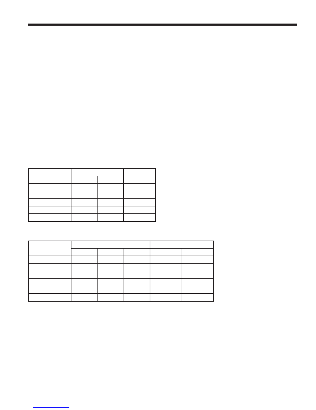
Single Speed Operation Logic
OPERATION
Compressor On Off On
Fan On On On
Loop Pump On Off On
Reversing Valve Off Off On
T-Stat Signal Y1 W Y1, O
HEATING COOLING
STG1 STG2 STG1
Dual Capacity Operation Logic
OPERATION
Compressor-Low On Off Off On Off
Compressor-Hi Off On Off Off On
Fan On On On On On
Loop Pump On On Off On On
Reversing Valve Off Off Off On On
T-Stat Signal Y1 Y1, Y2 W Y1, O Y1, Y2, O
STG1 STG2 STG3 STG1 STG2*
HEATING COOLING
19
Page 20
ES SPLIT INSTALLATION MANUAL
Checking Superheat and Subcooling
Determining Superheat
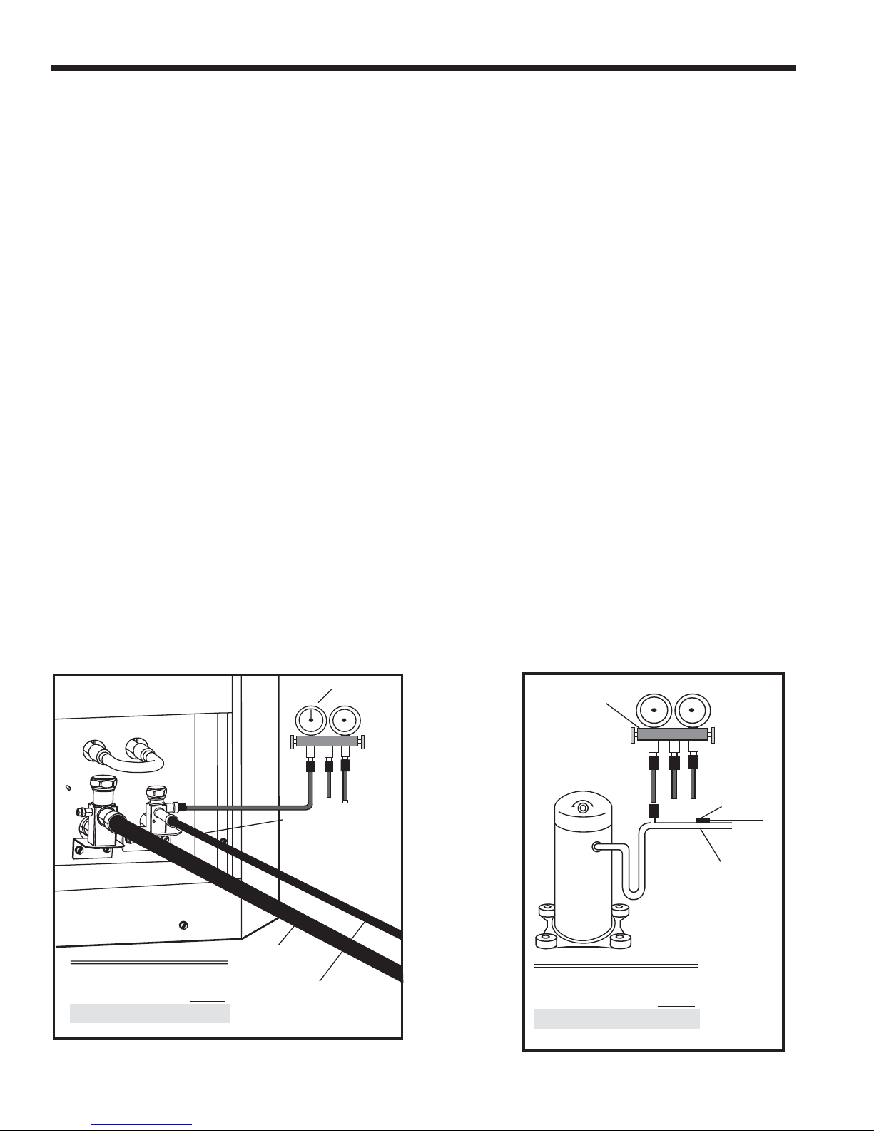
Measure the temperature of the suction line at the point where the expansion valve bulb is clamped.
1.
Determine the suction pressure in the suction line by attac hing refrigeration gauges to the schrader connection on
2.
the suction side of the compressor.
Convert the pressure obtained in Step 2 to the saturation temperature by using the R-410A Pressure/Temperature
3.
Conversion Chart on page 26.
Subtract the temperature obtained in Step 3 from Step 1. The difference is the amount of superheat for the unit. Refer
4.
to tables on pages 21-22 for superheat ranges at specifi c entering water conditions. The fi gure below illustrates a
typical example of how to measure superheat on the unit using R-410A. The temperature of the suction line at the
sensing bulb is 50°F. The suction pressure at the compressor is 114 PSIG which is equivalent to 38°F saturation
temperature (R-410A Pressure/Temeprature Conversion Chart, page 26).
50°F - 38°F = 12°F Superheat
Determining Subcooling
Measure the temperature of the liquid line on the small refrigerant line (liquid line) just outside the split cabinet. This
1.
location will be adequate for measurement in both modes unless a signifi cant temperature drop in the liquid line is
anticipated.
Measure the liquid line pressure by attaching refrigerant gauges to the schrader connection on the liquid line service
2.
valve.
Convert the pressure obtained in Step 2 to the saturation temperature by using the R-410A Pressure/Temperature
3.
Conversion Chart on page 26.
Subtract the temperature in Step 1 from the temperature in Step 3. The difference will be the subcooling value for
4.
that unit. Refer to tables on pages 21-22 for values at specifi c entering water temperatures. The fi gures below
illustrate a typical example of measuring refrigeration subc o oling using R-410A. The temperature of the liquid line
after leaving the condensing coil is 90°. The liquid line pressure at the service valve is 356 PSIG, which is equivalent
to 108°F.
108°F - 90°F = 18°F Subcooling
Figure 11: Subcooling Check
Suction Line
356 psig (see chart) = 108oF
Liquid Line = -90
Subcooling = 18oF
o
F
356 psig
=108°F
Temperature of Liquid Line
Outside the ES Cabinet.
Use in Both Modes.
T emperatureof Liquid
Line
= 90°F
Liquid Line
Figure 12: Superheat Check
114psig=38°F
Suction Line = 50oF
114psig (see chart) = -38
Superheating = 12
o
F
o
F
Temperature
at Suction of
Compressor
=50°F
Expansion
ValveBulb
20
Page 21
ES SPLIT INSTALLATION MANUAL
Checking Superheat and Subcooling (cont.)
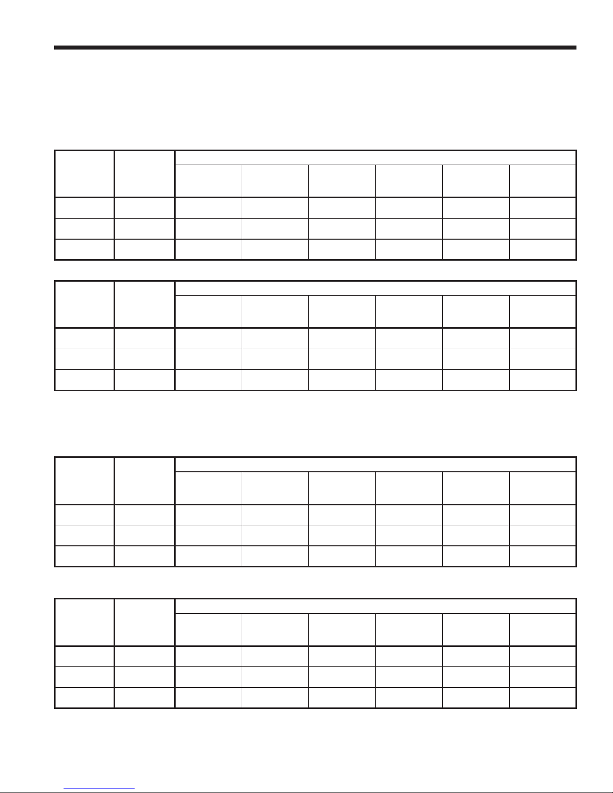
Superheat, Subcooling, Pressures and Water/Air Temperatures
First Stage Operation
ENTERING
WATER
TEMP °F
50
70
90
WATER
FLOW
GPM/TON
1.5
3.0
1.5
3.0
1.5
3.0
SUCTION
PRESSURE
PSIG
144-155
142-153
145-157
145-155
155-165
153-163
DISCHARGE
PRESSURE
PSIG
195-203
180-186
257-264
242-249
330-340
315-325
COOLING - NO DESUPERHEATER
SUPERHEAT SUBCOOLING
10-14
10-14
10-14
10-14
10-14
10-14
8-12
8-12
8-12
8-12
8-12
8-12
WATER
TEMP
RISE °F
21-25
10-15
20-24
9-13
18-22
8-12
AIR TEMP
DROP °F
DB
18-22
18-22
17-21
17-21
16-20
16-20
ENTERING
WATER
TEMP °F
30
50
70
WATER
FLOW
GPM/TON
1.5
3.0
1.5
3.0
1.5
3.0
SUCTION
PRESSURE
76-84
80-88
112-120
116-124
141-151
145-155
Note: * Deduct 25# psig for ES036.
Second Stage Operation
ENTERING
WATER
TEMP °F
50
70
90
WATER
FLOW
GPM/TON
1.5
3.0
1.5
3.0
1.5
3.0
SUCTION
PRESSURE
126-132
124-130
132-139
131-137
139-145
137-143
PSIG
PSIG
DISCHARGE*
PRESSURE
PSIG
250-265
255-270
290-310
295-315
300-325
305-330
DISCHARGE
PRESSURE
PSIG
223-237
198-212
285-295
255-275
365-385
335-355
HEATING - NO DESUPERHEATER
SUPERHEAT SUBCOOLING
6-10
6-10
8-12
8-12
10-14
10-14
COOLING - NO DESUPERHEATER
SUPERHEAT SUBCOOLING
12-16
12-16
10-14
10-14
9-13
9-13
2-8
2-8
2-10
2-10
4-12
4-12
10-16
10-16
10-16
10-16
10-16
10-16
WATER
TEMP
DROP °F
4-6
2-4
6-8
4-6
7-9
5-7
WATER
TEMP
RISE °F
20-24
10-14
19-23
9-13
18-22
8-12
AIR TEMP
RISE °F
DB
12-16
14-18
18-22
20-24
26-30
28-32
Rev. 08/08/05
AIR TEMP
DROP °F
DB
18-22
18-22
17-21
17-21
16-20
16-20
ENTERING
WATER
TEMP °F
30
50
70
WATER
FLOW
GPM/TON
1.5
3.0
1.5
3.0
1.5
3.0
SUCTION
PRESSURE
PSIG
66-74
70-78
96-106
100-110
126-141
130-145
Note: * Deduct 10# psig for ES036.
DISCHARGE*
PRESSURE
PSIG
280-310
285-315
309-335
314-339
335-375
340-380
HEATING - NO DESUPERHEATER
SUPERHEAT SUBCOOLING
6-10
6-10
10-14
10-14
12-16
12-16
10-16
10-16
14-18
14-18
18-24
18-24
21
WATER
TEMP
DROP °F
5-7
3-5
6-8
4-6
9-11
7-9
AIR TEMP
RISE °F
DB
15-21
17-23
22-28
24-30
30-36
32-38
Rev. 08/08/05
Page 22
ES SPLIT INSTALLATION MANUAL
Checking Superheat and Subcooling (cont.)
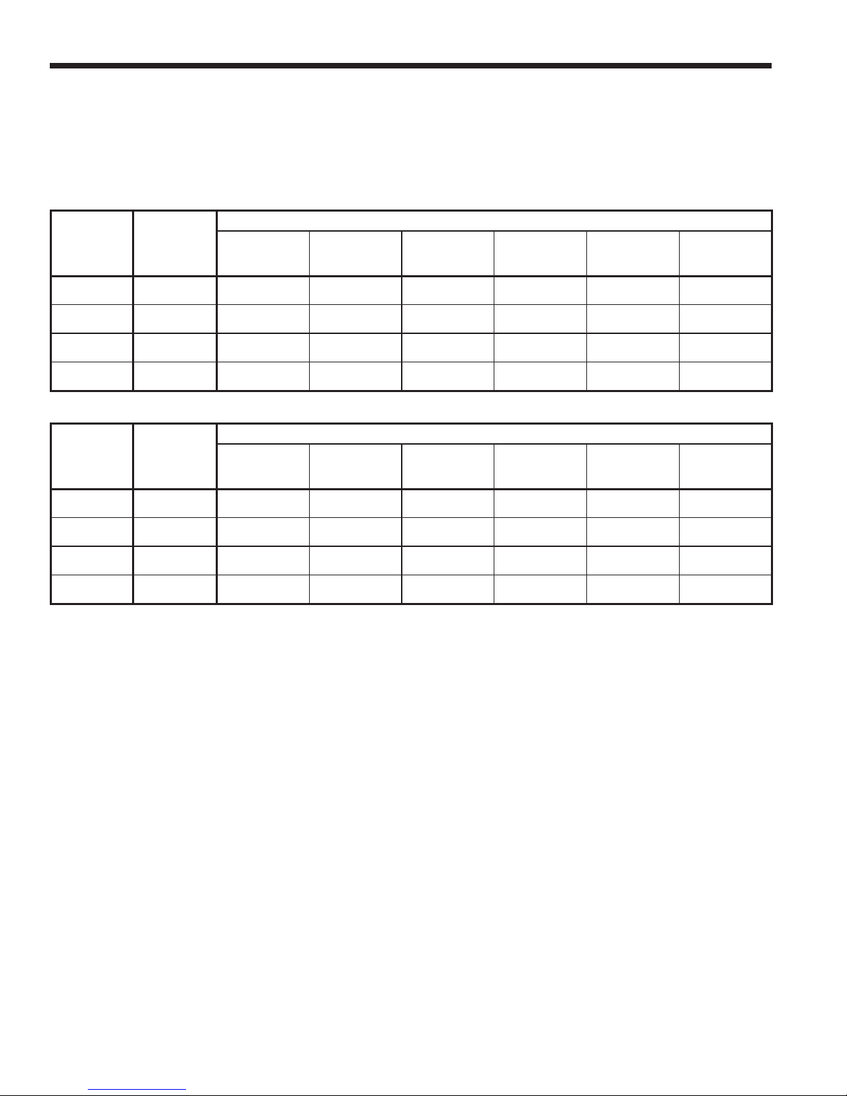
Superheat, Subcooling, Pressures and Water/Air Temperatures (cont.)
Single Speed Units
ENTERING
WATER
TEMP °F
30
50
70
90
ENTERING
WATER
TEMP °F
30
50
70
90
WATER
FLOW
GPM/TON
1.5
3.0
1.5
3.0
1.5
3.0
1.5
3.0
WATER
FLOW
GPM/TON
1.5
3.0
1.5
3.0
1.5
3.0
1.5
3.0
SUCTION
PRESSURE
PSIG
-
-
127-133
125-130
136-144
134-142
141-149
139-147
SUCTION
PRESSURE
PSIG
74-77
78-84
95-114
109-118
136-146
140-150
-
-
DISCHARGE
PRESSURE
PSIG
-
-
220-235
190-210
280-300
250-270
360-380
330-350
DISCHARGE
PRESSURE
PSIG
285-310
290-315
315-345
320-350
355-395
360-390
-
-
COOLING - NO DESUPERHEATER
SUPERHEAT SUBCOOLING
-
-
13-19
13-19
11-15
11-15
10-14
10-14
HEATING - NO DESUPERHEATER
SUPERHEAT SUBCOOLING
8-12
8-12
9-13
9-13
10-14
10-14
-
-
-
-
10-16
10-16
8-14
8-14
8-14
8-14
3-9
3-9
5-11
5-11
6-12
6-12
-
-
WATER
TEMP
RISE °F
-
-
19-23
9-12
19-23
9-12
18-22
9-12
WATER
TEMP
DROP °F
5-7
3-5
7-9
5-7
9-11
7-9
-
-
AIR TEMP
DROP °F
DB
-
-
18-22
18-22
17-21
17-21
16-20
16-20
AIR TEMP
RISE °F
DB
12-18
14-20
18-24
20-26
24-30
26-32
-
-
22
Page 23

ES SPLIT INSTALLATION MANUAL
Pressure Drop & Recommended Flow Rates
UNIT
ES024
ES030
ES036
ES048
ES060
ES072
(PSI CHANGE THROUGH HEAT EXCHANGER AT EWT ºF)
30° 50° 70° 90° 110° GPM
1.0 1.0 0.8 0.8 0.7 3.0
1.9 1.8 1.6 1.5 1.3 4.5
2.9 2.7 2.6 2.5 2.4 6.0
1.7 1.6 1.5 1.4 1.3 4.0
2.9 2.7 2.6 2.5 2.4 6.0
4.7 4.4 4.2 4.0 3.8 8.0
0.8 0.7 0.7 0.7 0.6 3.0
1.2 1.2 1.1 1.0 1.0 4.0
1.8 1.7 1.5 1.5 1.4 5.0
3.1 2.9 2.8 2.7 2.5 7.0
5.0 4.7 4.5 4.3 4.1 9.0
1.4 1.3 1.2 1.2 1.1 3.0
2.1 2.0 2.0 1.9 1.8 6.0
3.7 3.5 3.3 3.3 3.0 9.0
5.9 5.6 5.4 5.2 4.8 12.0
1.1 1.0 0.9 0.9 0.9 5.0
2.1 2.0 2.0 1.9 1.8 8.0
3.1 2.9 2.8 2.7 2.6 11.0
4.8 4.6 4.4 4.2 3.9 14.0
1.5 1.4 1.3 1.2 1.1 7.0
2.7 2.6 2.4 2.3 2.2 10.0
4.3 4.1 3.8 3.6 3.4 13.0
6.1 5.8 5.4 5.1 4.8 16.0
FLOW RATE (GPM)
CLOSED LOOP WELL WATER
4.5 - 6 3 - 4
6 - 8 4 - 5
4 - 5 Lo cap 3 - 4 Lo cap
7 - 9 Hi cap 6 - 7 Hi cap
6 - 9 Lo cap 3 - 4 Lo cap
9 - 12 Hi cap 6 - 7 Hi cap
8 - 11 Lo cap 5 - 6 Lo cap
11 - 14 Hi cap 8 - 9 Hi cap
10 - 13 Lo cap 7 - 8 Lo cap
13 - 16 Hi cap 10 - 11 Hi cap
23
Page 24

ES SPLIT INSTALLATION MANUAL
Service
Should a problem develop, refer to the following information for possible causes and corrective steps:
If neither fan nor compressor run:
The fuse may be blown or the circuit breaker may be open. Check electrical circuits and motor windings for shorts or
1.
grounds. Investigate for possible over loading. Replace fuse or reset circuit breakers after fault is corrected.
Supply voltage may be too low. Check it with a VOM.
2.
Control system may be faulty. Check thermostat for correct wiring and check 24-volt transformer.
3.
Wires may be loose or broken. Replace or tighten.
4.
If fan operates and the compressor doesn’t:
The low pressure switch may have tripped due to:
1.
a. fouled or plugged coaxial heat exchanger (heating).
b. lack of or no water fl ow (heating).
c. water too cold (heating).
d. not enough air over the air coil due to dirty fi lters (cooling).
e. air coil or fan motor failure (cooling).
f. lack of refrigernat (heating or cooling).
The high pressure may have tripped due to:
2.
a. fouled or plugged coaxial heat exchanger (cooling).
b. lack of or no water fl ow (cooling).
c. water too warm (cooling).
d. not enough airfl ow over the air coil due to dirty fi lters (heating).
e. air coil or fan motor failure (heating).
Check capacitor.
3.
Wires may be loose or broken. Replace or tighten.
4.
The compressor overload protection may be open. If the compressor dome is extremely hot, the overload will not reset
5.
until it has cooled down. If the overload does not reset when cool, it may be defective. Replace the compressor.
The internal winding of the compressor motor may be grounded to the compressor shell. This should cause breaker to
6.
trip when voltage is applied. If so, replace the compressor.
The compressor winding may be open. Check continuity with ohmmeter. If the winding is open, replace the compres-
7.
sor. Make sure compressor is cool before checking windings.
Check thermostat setting, calibration and wiring.
8.
If suffi cient cooling or heating is not obtained:
Check thermostat for improper location. Make sure hole in wall behind thermostat is sealed properly.
1.
Check and clean the fi lter. Airfl ow may be insuffi cient.
2.
Check for restriction in water fl ow.
3.
Check superheat and subcooling for possible refrigerant problem. Refer to pages 18-19 for proper numbers.
4.
The reversing valve may be defective and creating a bypass of refrigerant. If the unit will not cool, check the reversing
5.
valve coil.
If the unit operation is noisy:
Check for fan wheel hitting the housing. Adjust for clearance.
1.
Check for bent fan wheel. Replace if damaged.
2.
Check for loose fan wheel on the shaft. Tighten it.
3.
Check compressor mounting bolts. Make sure compressor is fl oating free on its isolator mounts.
4.
Check for tubing touching the compressor or other surfaces. Readjust it by bending slightly.
5.
Check screws on all panels.
6.
Check for chattering or humming in the contactor or relays due to low voltage or a defective holding coil. Replace the
7.
component.
Check for proper installation of vibration absorbing material under the unit. Unit must be fully supported, not just on
8.
corners.
Check for abnormally high discharge pressures.
9.
24
Page 25
Service ( con t.)
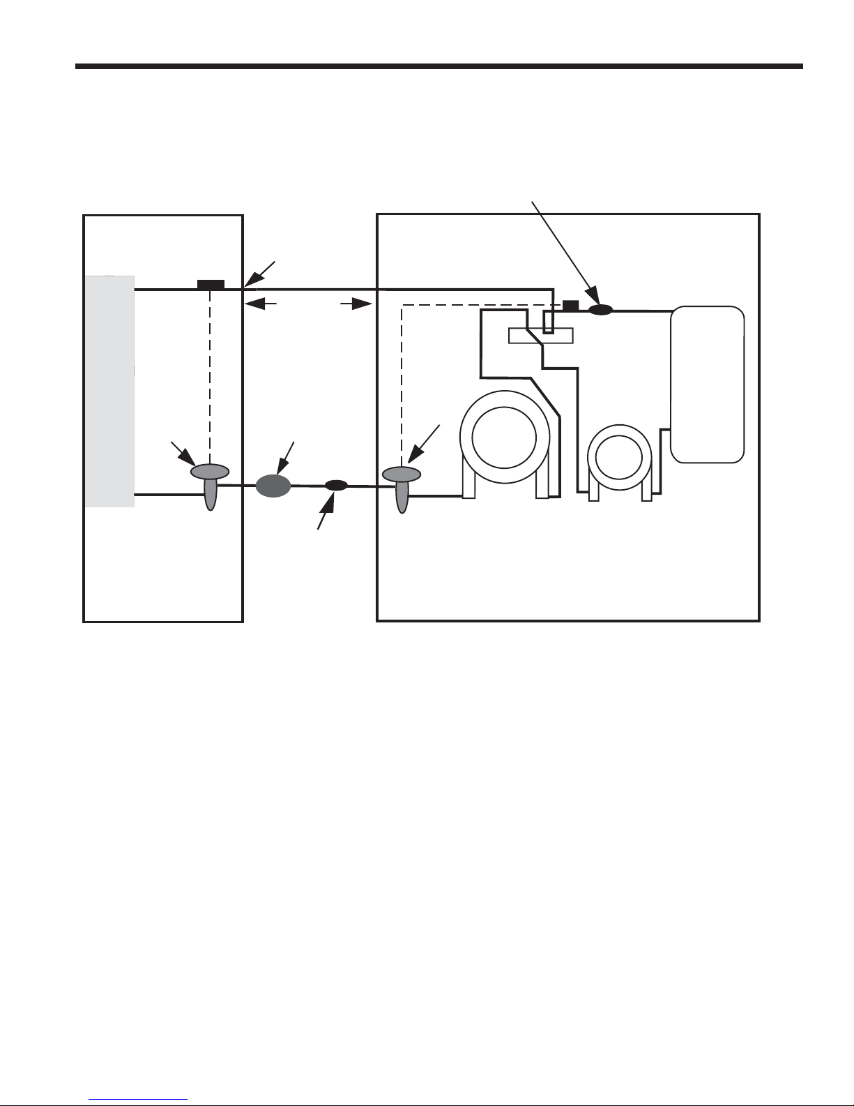
Refrigeration Schematic and Troubleshooting Form
Measure suction temperature
here at TXV bulb in heating modes.
Measure suction
temperature here
at TXV bulb in
cooling modes.
Line set
length
ES SPLIT INSTALLATION MANUAL
Suct PSI____
Suct sat temp____
Suct temp____
Superheat____
n
Suctio
Air
Coi
l
Clg TXV
COOLING TXV -ACTIVE
RIGHT TO LEFT
Bi-flow
filter/drier
Measure liquid line
temperature and
pressure here in
both heating and
cooling modes
Htg TXV
COAX
Desuperheater
Discharge PSI____
Disch. sat temp____
Liquid temp____
Subcooling____
HEATING TXV -ACTIVE LEFT TO RIGHT
Com
p
Discharge
25
Page 26
ES SPLIT INSTALLATION MANUAL
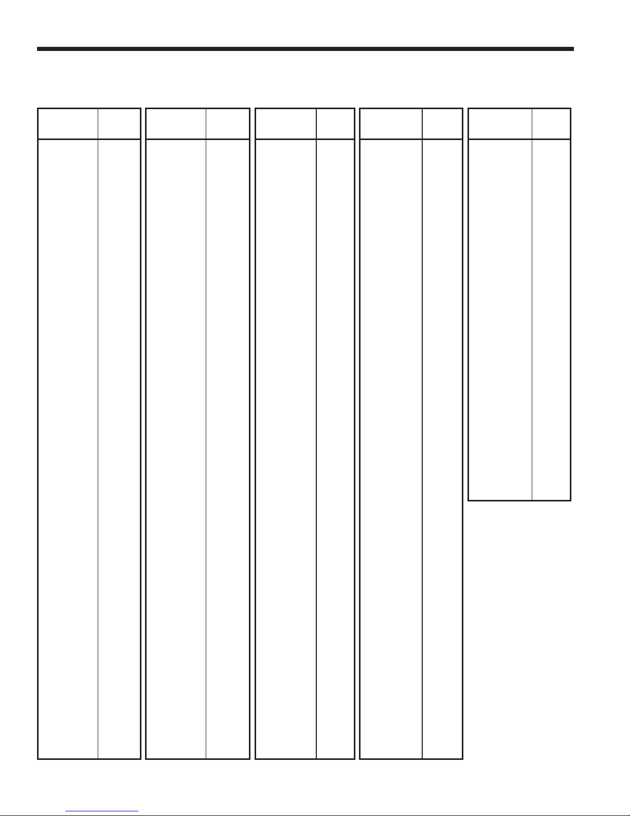
Pressure/Temperature Coversion Chart for R-410A
PRESSURE
(PSIG)
60 8.5 180 63.5 300 96.3 420 120.6 540 140.0
62 9.9 182 64.2 302 9 6. 8 422 120.9 542 140.3
64 11.2 184 64.8 304 97.2 424 121.3 544 140.6
66 12.5 186 65.5 306 97.7 426 121.6 546 140.9
68 13.8 188 66.1 308 98.1 428 122.0 548 141.2
70 15.1 190 66.8 310 98.6 430 122.3 550 141.4
72 16.3 192 67.4 312 99.0 432 122.7 552 141.7
74 17.5 194 68.0 314 99.5 434 123.0 554 142.0
76 18.7 196 68.7 316 99.9 436 123.4 556 142.3
78 19.8 198 69.3 318 100.4 438 123.7 558 142.6
80 21.0 200 69.9 320 100.8 440 124.1 5 6 0 142.9
82 22.1 202 70.5 322 101.2 442 124.4 562 143.2
84 23.2 204 71.1 324 101.7 444 124.8 564 143.5
86 24.3 206 71.7 326 102.1 446 125.1 566 143.7
88 25.4 208 72.3 328 102.5 448 125.4 568 144.0
90 26.5 210 72.9 330 103.0 450 125.8 570 144.3
92 27.5 212 73.5 332 103.4 452 126.1 572 144.6
94 28.6 214 74.1 334 103.8 454 126.5 574 144.9
96 29.6 216 74.7 336 104.2 456 126.8 576 145.1
98 30.6 218 75.3 338 104.7 458 127.1 578 145.4
100 31.6 220 75.8 340 105.1 460 127.5 580 145.7
102 32.6 222 76.4 342 105.5 462 127.8 582 146.0
104 33.5 224 77.0 344 105.9 464 128.1 584 146.2
106 34.5 226 77.5 3 46 106.3 466 128.5 586 146.5
108 35.4 228 78.1 348 106.7 468 128.8 588 146.8
110 36.4 230 78.7 350 107.2 470 129.1 590 147.1
112 37.3 232 79.2 352 107.6 472 129.4 592 147.3
114 38.2 234 79.8 354 108.0 474 129.8 594 147.6
116 39.1 23 6 80.3 356 108.4 476 130.1 596 147.9
118 40.0 238 80.9 358 108.8 478 130.4 598 148.2
120 40.9 240 81.4 360 109.2 480 130.7 600 148.4
122 41.7 242 81.9 362 109.6 482 131.1 602 148.7
124 42.6 244 82.5 3 64 110.0 484 131.4 604 149.0
126 43.4 246 83.0 366 110.4 486 131.7 606 149.2
128 44.3 248 83.5 368 110.8 488 132.0
130 45.1 250 84.1 370 111.2 490 132.3
132 45.9 252 84.6 372 111.6 492 132.7
134 46.7 254 85.1 374 112.0 494 133.0
136 47.5 256 85.6 376 112.3 496 133.3
138 48.3 258 86.1 378 112.7 498 133.6
140 49.1 260 86.6 380 113.1 500 133.9
142 49.9 262 87. 1 382 113.5 502 134.2
144 50.7 264 87.7 384 113.9 504 134.5
146 51.5 266 88.2 386 114.3 506 134.9
148 52.2 268 88.7 388 114.7 508 135.2
150 53.0 270 89.2 390 115.0 510 135.5
152 53.7 272 89.6 392 115.4 512 135.8
154 54.5 274 90.1 394 115.8 514 136.1
156 55.2 276 90.6 396 116.2 516 136.4
158 55.9 278 91.1 398 116.5 518 136.7
160 56.6 280 91.6 400 116.9 520 137.0
162 57.4 282 92.1 402 117.3 522 137.3
164 58.1 284 92.6 404 117.6 524 137.6
166 58.8 286 93.0 406 118.0 52 6 137.9
168 59.5 288 93.5 408 118.4 528 138.2
170 60.2 290 94.0 410 118.7 530 138.5
172 60.8 292 94.5 412 119.1 532 138.8
174 61.5 294 94.9 414 119.5 534 139.1
176 62.2 296 95.4 416 119.8 536 139.4
178 62.9 298 95.8 418 120.2 538 139.7
TEMP°FPRESSURE
(PSIG)
TEMP
°F
PRESSURE
(PSIG)
TEMP °FPRESSURE
(PSIG)
TEMP
°F
PRESSURE
(PSIG)
608 149.5
TEMP
°F
26
Page 27

ES SPLIT INSTALLATION MANUAL
Preventive Maintenance
Water Coil Maintenace
Keep all air out of the water. An open loop system should be checked to ensure that the well head is not allowing air to
1.
infi ltrate the water line. Lines should always be airtight.
Keep the system under pressure at all times. It is recommended in open loop systems that a water control valve be
2.
placed in the discharge line to prevent loss of pressure during off cycles. Closed loop systems must have positive static
pressure or airvents may draw air into the system.
If the installation is performed in an area with a known high mineral content in the water, it is best to establish a periodic
3.
maintenance schedule with the owner when the coil can be checked on a regular basis. (the manufacturer recommends cleaning once a year in poor water areas). Should coil cleaning be necessary, use standard coil cleaning procedures which are compatible with either the cupronickel or copper water-to-refrigerant heat exchanger. Generally, the
more water fl owing through the unit, the less chance there is for scaling. Low water fl ow rates produce higher tempera-
tures through the coil and increase the possibility of scale buildup during cooling. To avoid excessive pressure drop
and the possibility of copper erosion, do not exceed GPM fl ow rate as shown on the specifi cation sheets for each unit.
Filter/Coil Maintenance
Filters must be clean to obtain maximum performance. They should be inspected every two to three months under
normal operating conditions and be replaced when necessary. Units should never be operated without a fi lter.
In areas where airborne bacteria produce a slime in the drain pan, it may be necessary to treat chemically to minimize
the problem. The condensate drain can pick up lint and dirt, especially with dirty fi lters. Inspect twice a year to avoid the
possibility of overfl ow.
The air coil must be cleaned to obtain maximum performance. Check once a year under normal operating conditions
and, if dirty, brush or vacuum clean. Care must be taken not to damage the aluminum fi ns while cleaning.
Replacement Procedures
Obtaining Parts
When ordering replacement parts, refer to the model number and serial number of the unit as stamped on the serial
plate attached to the unit. If replacement parts are required, mention the date of installation of the unit and the date of failure, along with an explanation of the malfunctions and a description of the replacement parts required.
In-Warranty Material Return
Material may not be returned except by permission of authorized service personnel. Contact your local distributor for
warranty return authorization and assistance.
27
Page 28

Manufactured by WFI
9000 Conservation Way
Fort Wayne, IN 46809
WFI has a policy of continuous product research and
development and reserves the right to change design
and specifi cations without notice.
©2006 WFI.
Product: ES Split
Type: Geothermal/Water Source Heat Pumps
Size: 2 thru 6 Ton
Document Type: Installation Manual
Part Number: IM1460
Release Date: 11/06
Supercedes: IM1460 (10/05)
 Loading...