

Page 1
Geothermal/Water Source Heat Pumps
• R-410A Refrigerant
• 2 thru 6 Ton
Installation Information
Water Piping Connections
Desuperheater Connections
Electrical
Startup Procedures
Troubleshooting
Preventive Maintenance
E Series Installation Manual
IM2502 09/04
WFI
Page 2
E SERIES INSTALLATION MANUAL
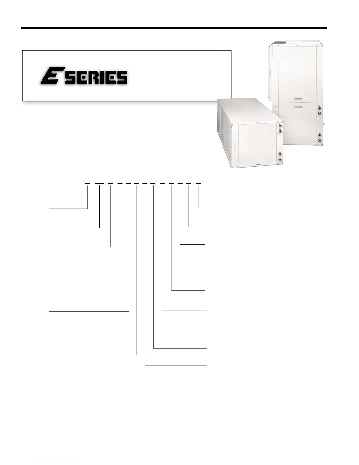
Family
E Series R-410A
Unit Capacity
MBTUH
Discharge Air Configuration
T = Top (Vertical)
B = Bottom (Vertical)
E = End (Horizontal)
S = Side (Horizontal)
Return Air Configuration
L = Left
R= Right
Voltage
0 = 208-230/60/1
1 = 208-230/60/1 (Residential)
2 = 265/60/1
3 = 208-230/60/3
4 = 460/60/3
Hot Water Option
0 = None
1 = Hot Water Generation (208-230/1 only)
With Factory Installed Pump
Note: *FX10 available only on units with PSC blowers without desuperheaters
Blower Options
0 = PSC Blower
1 = ECM Blower (Standard on 036, 048, 060, 072)
2 = Oversized ECM Blower
(040, 047, 048 only)
Coax Options
N = Cupronickel
Sound Kit
A = None (040, 047, 058, 066)
B = Blanket (Standard on 024, 030,
035, 036, 048, 060, 072;
Optional on 040, 047, 058, 066)
Filter Options
D = 1" Pleated Disposable
Non-Standard Options
S = No options
4 = FX10*
5 = FX10 w/N2 Open com. card*
6 = FX10 w/Lonworks com. card*
7 = FX10 w/BacNet com. card*
Non-Standard Option Details
S = STD
Vintage
A = Current
E 024 T L 0 0 1 N B D S S A
Model Nomenclature
2
Page 3

E SERIES INSTALLATION MANUAL
Table of Contents
General Installation Information 4-6
Water Piping and Condensate 6-7
Closed Loop Ground Source Systems 8
Open Loop Ground Water Systems 9
Desuperheater Connection & Startup 10-11
Electrical Connections 12
Electronic Thermostat Installation 13
Setting Fan Speed 13
Fan Performance Tables 14-15
Standard Microprocessor Control 16-18
Optional FX10 Microprocessor Control 19
Unit Startup 20
Description of Unit Operation 21-22
Operation Logic 22
Unit Operating Parameters 23-24
Pressure Drop & Recommended Flow Rates 25
Troubleshooting 26
Preventive Maintenance 27
Replacement Procedures 27
3
Page 4
E SERIES INSTALLATION MANUAL
Vibration
Absorbing
Mesh
or
Air
Pad
General Installation Information
Safety Considerations
WARNING: Before performing service or maintenance operations on a system, turn off main
power switches to the indoor unit. If applicable, turn off the accessory heater power switch.
Electrical shock could cause personal injury.
Installing and servicing heating and air conditioning equipment can be hazardous due to system pressure and electrical
components. Only trained and qualified service personnel should install, repair or service heating and air conditioning equipment. Untrained personnel can perform the basic maintenance functions of cleaning coils and cleaning and replacing filters.
All other operations should be performed by trained service personnel. When working on heating and air conditioning equipment, observe precautions in the literature, tags and labels attached to the unit and other safety precautions that may apply.
Follow all safety codes. Wear safety glasses and work gloves. Use a quenching cloth for brazing operations and have a
fire extinguisher available.
Moving and Storage
Move units in the normal “up” orientation. Horizontal units may be moved and stored per the information on the packaging. Do not stack more than three units in total height. Vertical units may be stored one upon another to a maximum height
of two units. Do not attempt to move units while stacked. When the equipment is received, all items should be carefully
checked against the bill of lading to be sure all crates and cartons have been received. Examine units for shipping damage,
removing the units from the packaging if necessary. Units in question should also be internally inspected. If any damage is
noted, the carrier should make the proper notation on the delivery receipt, acknowledging the damage.
Unit Location
Locate the unit in an indoor area that allows for easy removal of the filter and access panels. Location should have
enough space for service personnel to perform maintenance or repair. Provide sufficient room to make water, electrical
and duct connection(s). If the unit is located in a confined space, such as a closet, provisions must be made for return air
to freely enter the space by means of a louvered door, etc. Any access panel screws that would be difficult to remove after
the unit is installed should be removed prior to setting the unit. On horizontal units, allow adequate room below the unit for
a condensate drain trap and do not locate the unit above supply piping. Care should be taken when units are located in
unconditioned spaces to prevent damage from frozen water lines and excessive heat that could damage electrical
components.
Installing Vertical Units
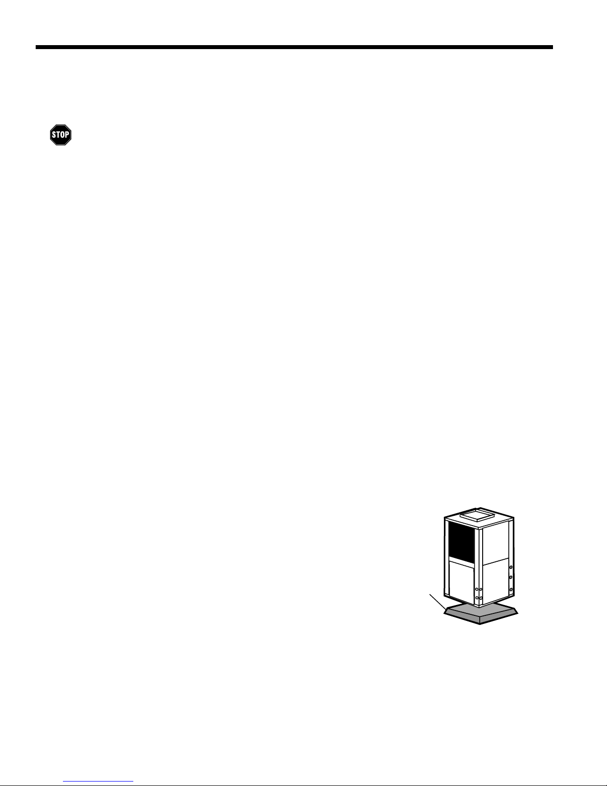
Vertical units are available in left or right air return configurations. Top flow
vertical units should be mounted level on a vibration absorbing pad slightly larger
than the base to provide isolation between the unit and the floor. It is not necessary
to anchor the unit to the floor (see right).
Bottom flow units should be mounted level and sealed well to floor to prevent
air leakage. Bottom flow units require the supply air opening to be cut at least 1/2inch larger than the unit’s air outlet. Protect the edges of combustible flooring with
sheet metal over-wrap or other non-combustible material.
If access to the left side of the unit will be limited after installation, remove the
two mounting screws on the left side of the control box before setting the unit (leave
the two front mounting screws intact). This will allow the control box to be removed
with only the two front mounting screws for future service.
Figure 1: Vertical Unit Mounting
4
Page 5
E SERIES INSTALLATION MANUAL
Insulate supply
plenum and use
at least one 90
elbow to
reduce noise
Electrical
Disconnect
Flexible Duct
Collar
Threaded Rods
Line Voltage
B
a
l
l
V
a
l
v
e
s
Hose
Kits
ToLine
Power
To
Thermostat
Hanging
Brackets
(Included)
Building Water Loop
O
C
B
D
E
Compressor
Section
Air Handler
Section
A
Vibration Isolator
Washer
Hex Nuts
(not supplied)
Bolt and
Lockwasher
3/8”
Threaded Rod
(not supplied)
E024-035 (4 hangers included)
E036-072 (6 hangers included)
Installing Horizontal Units
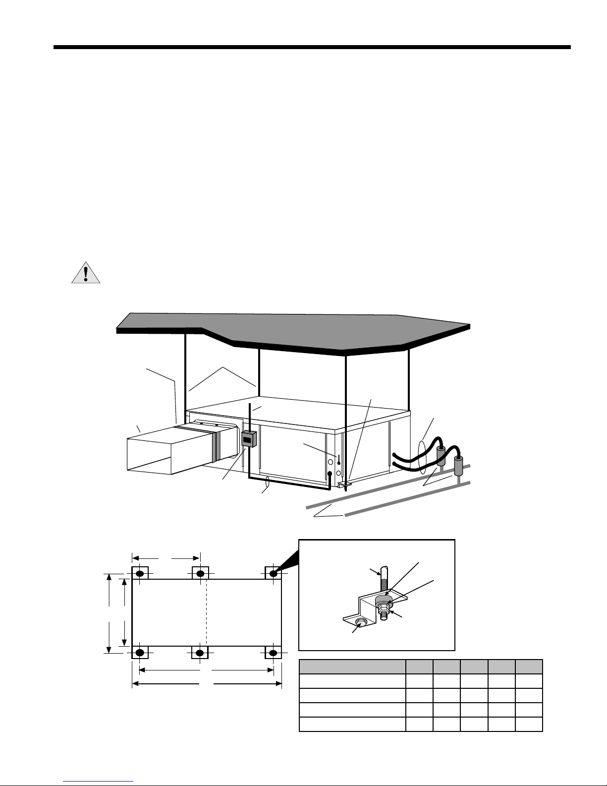
Horizontal units are available with side or end discharge and may be field converted from one to the other by replacing the discharge panel with a new panel which must be ordered separately. Horizontal units are normally suspended from
a ceiling by four or six 3/8-inch diameter threaded rods. The rods are usually attached to the unit by hanger bracket kits
furnished with each unit.
Lay out the threaded rods per the dimensions below. Assemble the hangers to the unit as shown. Securely tighten the
brackets to the unit using the weld nuts located on the underside of the bottom panel. When attaching the hanger rods to
the bracket, a double nut is required since vibration could loosen a single nut. To allow filter access, one bracket on the filter
side should be installed 180° from the position shown in the figure below. The unit should be pitched approximately 1/4-inch
towards the drain in both directions to facilitate the removal of condensate. Use only the bolts provided in the kit to attach
hanger brackets. The use of longer bolts could damage internal parts.
Some residential applications require the installation of horizontal units on an attic floor. In this case, the unit should
be set in a full size secondary drain pan on top of a vibration absorbing mesh. The secondary drain pan prevents possible
condensate overflow or water leakage damage to the ceiling. The secondary drain pan is usually placed on a plywood base
isolated from the ceiling joists by additional layers of vibration absorbing mesh.
CAUTION: Do not use rods smaller than 3/8-inch diameter since they may not be strong
enough to support the unit. The rods must be securely anchored to the ceiling.
Figure 2: Horizontal Unit Mounting
Figure 3: Hanger Location and Assembly
E024, E030, E035 24.8 61.5 22.5 63.0
E036, E040, E047, E048 27.8 70.5 25.5 72.0 29.9
E058, E060 27.8 75.5 25.5 77.0 29.9
E066, E072 27.8 80.5 25.5 82.0 29.9
5
MODEL A B C D E
–
Page 6
E SERIES INSTALLATION MANUAL
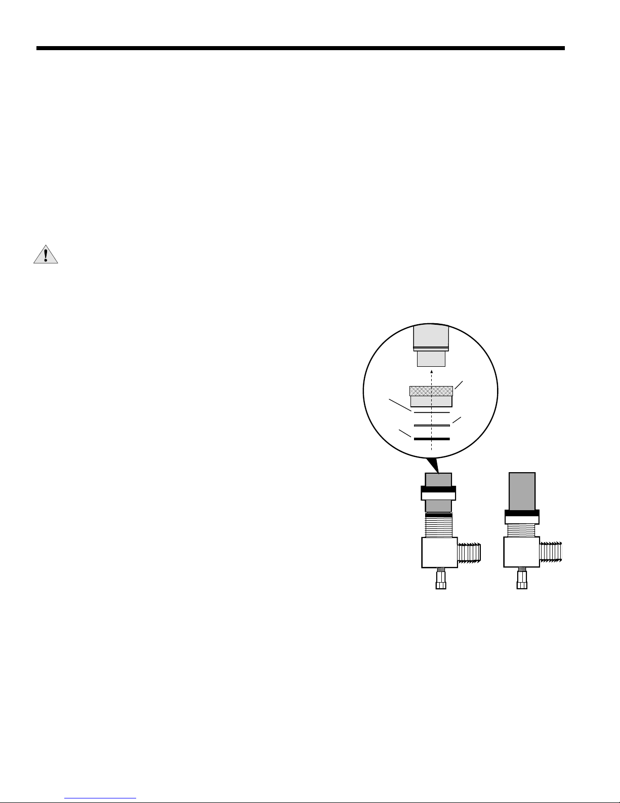
Locking
Ring
Stainless
Steel
Snap Ring
Gasket
Support
Sleeve
Gasket
Material
Duct System
An air outlet collar is provided on vertical top flow units and all horizontal units to facilitate a duct connection (vertical
bottom flow units have no collar). A flexible connector is recommended for discharge and return air duct connections on
metal duct systems. Uninsulated duct should be insulated with a minimum of 1-inch duct insulation. Application of the unit to
uninsulated ductwork in an unconditioned space is not recommended as the unit’s performance will be adversely affected.
If the unit is connected to existing ductwork, check the duct system to ensure that it has the capacity to accommodate
the air required for the unit application. If the duct is too small, as in the replacement of heating only systems, larger ductwork should be installed. All existing ductwork should be checked for leaks and repaired if necessary.
The duct system should be sized to handle the design airflow quietly and efficiently. To maximize sound attenuation of
the unit blower, the supply and return plenums should include an internal duct liner of fiberglass or constructed of ductboard
for the first few feet. On systems employing a sheet metal duct system, canvas connectors should be used between the
unit and the ductwork. If air noise or excessive airflow is a problem, the blower speed can be changed.
CAUTION: Be sure to remove the shipping material from the blower discharge before connecting
ductwork.
Water Piping
The proper water flow must be provided to each unit whenever the
unit operates. To assure proper flow, use pressure/temperature ports
to determine the flow rate. These ports should be located at the supply
and return water connections on the unit. The proper flow rate cannot
be accurately set without measuring the water pressure drop through
the refrigerant-to-water heat exchanger.
All source water connections on commercial units are fittings that
accept a male pipe thread (MPT). Insert the connectors by hand, then
tighten the fitting with a wrench to provide a leakproof joint. When connecting to an open loop (groundwater) system, thread any copper MPT
fitting into the connector and tighten in the same manner as described
above.
All source water connections on residential units are swivel piping
fittings (see Figure 4) that accept a 1-inch male pipe thread (MPT) .
The swivel connector has a rubber gasket seal similar to a rubber hose
gasket, which when mated to the flush end of any 1-inch threaded pipe
provides a leak-free seal without the need for thread sealing tape or
compound. Check to ensure that the rubber seal is in the swivel connector prior to attempting any connection. The rubber seals are shipped
attached to the waterline. To make the connection to a ground loop system, mate the brass connector (supplied in CK4L connector kit) against
the rubber gasket in the swivel connector and thread the female locking
ring onto the pipe threads, while maintaining the brass connector in the
desired direction. Tighten the connectors by hand, then gently snug
the fitting with pliers to provide a leak-proof joint. When connecting to
an open loop (ground water) system, thread any 1-inch MPT fitting (SCH80 PVC or copper) into the swivel connector and
tighten in the same manner as noted above. The open and closed loop piping system should include pressure/temperature
taps for serviceability.
The open and closed loop piping system should include pressure/temperature taps for serviceability. Never use flexible hoses smaller than 1-inch inside diameter on the unit. Limit hose length to 10 feet per connection. Check carefully for
water leaks.
Figure 4: Swivel Connections
(Residential Units)
6
Page 7
E SERIES INSTALLATION MANUAL
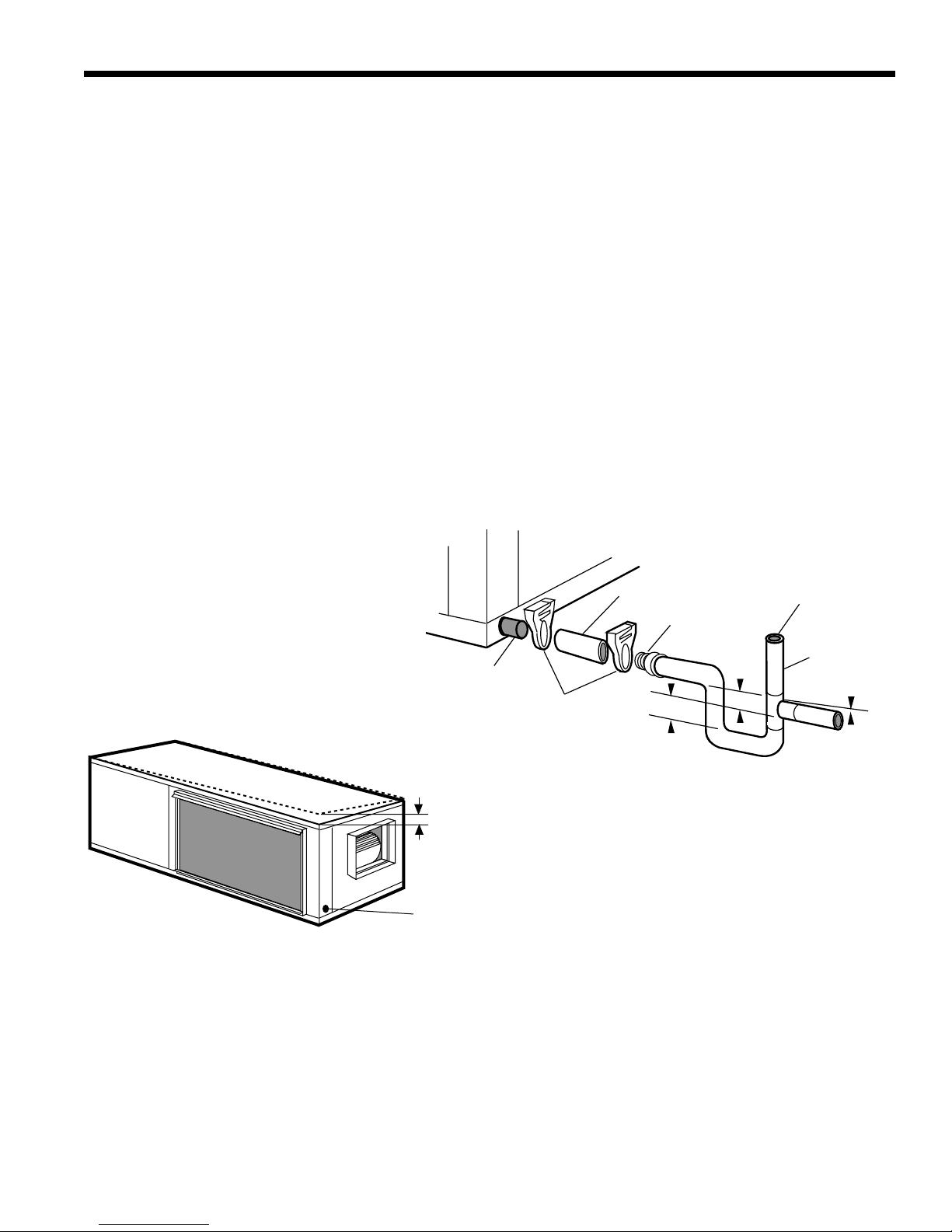
1/4'' Pitch
Drain
1.5"
1.5"
Vent (if needed)
3/4" PVC
3/4" barb to
glue adapter
1/8" per foot
Clear PVC hose
Plastic Hose Clamps
Copper tube stub
(Included with unit)
Water Quality
In ground water situations where scaling could be heavy or where biological growth such as iron bacteria will be present, a closed loop system is recommended. The heat exchanger coils in ground water systems may, over a period of time,
lose heat exchange capabilities due to a buildup of mineral deposits inside. These can be cleaned, but only by a qualified
service mechanic, as special solutions and pumping equipment are required. Desuperheater coils can likewise become
scaled and possibly plugged. In areas with extremely hard water, the owner should be informed that the heat exchanger
may require occasional flushing.
Freeze Protection
Set the freeze protection switch SW2-2 on the printed circuit board for applications using a closed loop antifreeze solution to “LOOP”. On applications using an open loop/ground water system (or closed loop no antifreeze), set this dip switch
to “WELL”, the factory default setting. (Refer to the Dip Switch Field Selection table on page 18.)
Condensate Drain
On vertical units, the internal condensate drain assembly consists of a drain tube which is connected to the drain pan, a
3/4-inch PVC female adapter and a flexible connecting hose. The female adapter may exit either the front or the side of the
cabinet. The adapter should be glued to the field-installed PVC condensate piping. On vertical upflow units, a condensate
hose is inside all cabinets as a trapping loop; therefore, an external trap is not necessary. On horizontal units, a copper stub
is provided for condensate drain piping connection. An external trap is required (see below). If a vent is necessary, an open
stand pipe may be applied to a tee in the field-installed condensate piping.
Figure 6: Unit Pitch for Drain
Figure 5: Horizontal Drain Connection
7
Page 8
E SERIES INSTALLATION MANUAL
E Series to
Electromechanical Units
Shut
Down
C C
SL2InSL2
Out
SL1InSL1
Out
E Series Unit #1
To Electromechanical Unit
C
S
Shut
Down
C C
SL2InSL2
Out
Shut
Down
C C
SL1InSL1
Out
SL2InSL2
Out
SL1InSL1
Out
Single Speed
E Series Unit #1
With pump
wired to Unit 1
With pump
wired to
Unit 2
E Series to E Series
Microprocessor Units
E Series Unit #2
Single Speed
With pump
wired to Unit 1
With pump
wired to
Unit 2
Shut
Down
C C
SL2InSL2
Out
Shut
Down
C C
SL1InSL1
Out
SL2InSL2
Out
SL1InSL1
Out
Dual Capacity
E Series Unit #1
E Series Unit #2
Dual Capacity
E Series to E Series
Microprocessor Units
Flexible Duct
Collar
Vibration Absorbing Pad
P/T Plugs
Drain
To Loop
or
Flow Center
Desuperheater
Connections
Auxiliary
Heater
Knockout
Low
Voltage to
Thermostat
Unit Supply
Auxiliary Heat
Supply
Insulated piping
or hose kit
Disconnects
(If Applicable)
Unit Power
Closed Loop Ground Source Systems
Note: For closed loop systems with antifreeze protection, set SW2-2 to the “loop” position (see table on page 18).
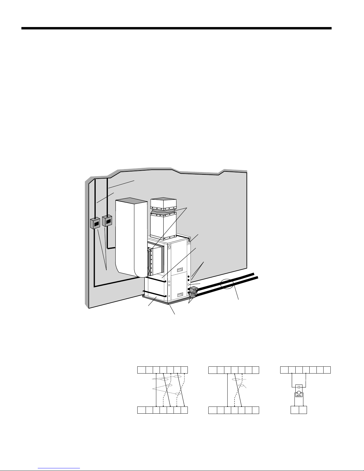
Once piping is completed between the unit, pumps and the ground loop (see figure below), final purging and charging
of the loop is required. A flush cart (or a 1.5 HP pump minimum) is needed to achieve adequate flow velocity in the loop
to purge air and dirt particles from the loop itself. Antifreeze solution is used in most areas to prevent freezing. Flush the
system adequately to remove as much air as possible then pressurize the loop to a static pressure of 40-50 PSI (summer)
or 50-75 PSI (winter). This is normally adequate for good system operation. Loop static pressure will fluctuate with the seasons. Pressures will be higher in the winter months than during the cooling season. This fluctuation is normal and should be
considered when initially charging the system.
After pressurization, be sure to remove the plug in the end of the loop pump motor(s) (if applicable) to allow trapped air
to be discharged and to ensure that the motor housing has been flooded. Ensure that the loop pumps provide adequate
flow through the unit(s) by checking the pressure drop across the heat exchanger and comparing it to the unit capacity data
in the specification catalog. Usually 2.5 to 3 GPM of flow per ton of cooling capacity is recommended in earth loop applications.
Figure 7: Closed Loop Ground Source Application
Multiple Units on
One Flow Center
When two units are connected to
one loop pumping system, pump control is
automatically achieved by connecting the
SL terminals on connector P2 in both units
with 2-wire thermostat wire. These terminals
are polarity dependant (see Figure 8). The
loop pump(s) may be powered from either
unit, whichever is more convenient. If either
unit calls, the loop pump(s) will automatically start. The use of two units on one flow
center is generally limited to a total of 20
GPM capacity.
Figure 8: Primary/Secondary Hook-up
8
Page 9
E SERIES INSTALLATION MANUAL
Solenoid Valve
Flow
Regulator
Use two valves for dual capacity units.
Use one valve for single speed units.
Flexible
Duct Collar
Vibration
Absorbing Pad
P/T Plugs
Drain
Desuperheater
Connections
Auxiliary
Heater
Knockout
Low Voltage
to Thermostat
and Valve
Unit Supply
Aux. Heat Supply
Water Out
Water In
Shut Off Valves
Boiler Drains
For HX Flushing
Disconnects
(IfApplicable)
Rubber Bladder
Expansion Tank
Solenoid
Valve
Shut Off Valves
(to isolate solenoid
valve while acid flushing)
Strainer
Flow Control
Valve
(on outlet of
Solenoid Valve)
Compressor
Line Voltage
R C Y1 Y2 W O G LO
Dual Capacity
Logic Board
Y1 From
Thermostat
1
23
1 2
3
Y2 From
Thermostat
Taco motorized valve #1
Taco motorized valve #2
CC
CCHI
CCH
CCL
Blk
Dual Capacity
Logic Board
CC GND
CCLO
SV1
Wh
Red
Stage 2
solenoid valve
SV2
Blk
Blk
Typical TwoStageexternal 24V water solenoid valves
(type PPV100 or BPV100) wiring
Note: switch SW2 - 3 to comp position
C
R
P1
1
Solenoid
Valve
2
ACC Com
2
1
ACC NC
ACC NO
3
Open Loop Ground Water Systems
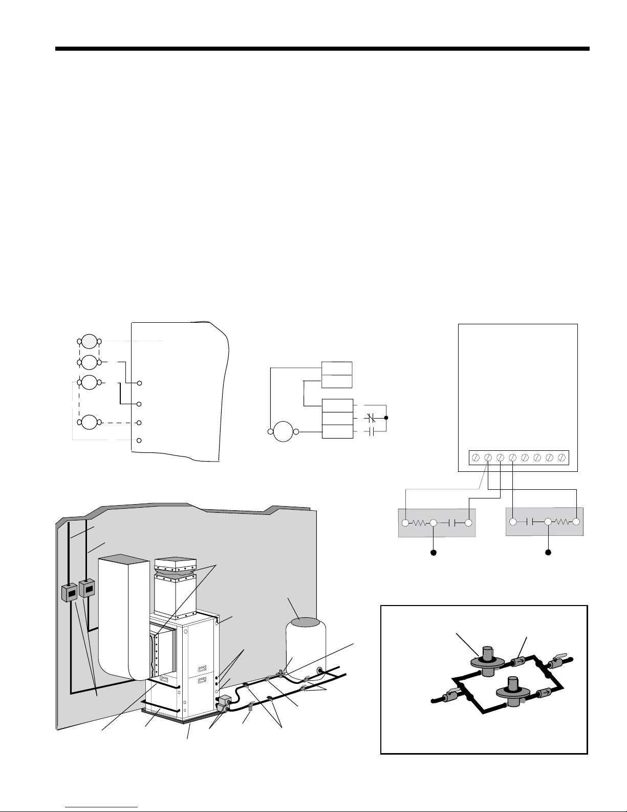
Typical open loop piping is shown below. Always maintain water pressure in the heat exchanger by placing water control
valves at the outlet of the unit to prevent mineral precipitation. Use a closed, bladder-type expansion tank to minimize
mineral formation due to air exposure. Insure proper water flow through the unit by checking pressure drop across the heat
exchanger and comparing it to the figures in unit capacity data tables in the specification catalog. Usually 1.5-2 GPM of flow
per ton of cooling capacity is recommended in open loop applications. In dual capacity units, stage 1 is half of the total tonnage. Therefore, on a E048, the stage 1 solenoid should flow 3-6 GPM and stage 1 & 2 together should flow 6-9 GPM.
Discharge water from the unit is not contaminated in any manner and can be disposed of in various ways, depending
on local codes, i.e. recharge well, storm sewer, drain field, adjacent stream or pond, etc. Most local codes forbid the use of
sanitary sewer for disposal. Consult your local building and zoning departments to assure compliance in your area.
Note: For open loop/groundwater systems or systems that do not contain an antifreeze solution, set SW2-Switch #2 to the
“WELL” position. (Refer to the table on page 18.) Slow opening/closing solenoid valves (type VM) are recommended to elimi
nate water hammer.
Figure 9: Open Loop Solenoid Valve Connection Options
-
Figure 10: Open System - Ground Water Application
Typical single stage external 24V
water solenoid valves (type PPV100
or BPV100) wiring.
Typical dual capacity external 24V
water solenoid valves (type VM )
9
Page 10
E SERIES INSTALLATION MANUAL
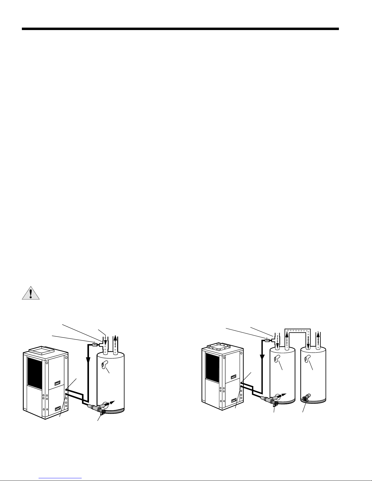
In
Venting Waste Valve
or Vent Coupling
3/4" x 3/4" x 1/2"
tee
Cold
Water In
Hot
Water Out
P/T Relief
Valve
P/T Relief
Valve
DHW
Water In
DHW
Water Out
Drain ValveDrain Valve
Drain Valve
In
P/T Relief
Valve
Cold
Water In
Hot
Water Out
DHW
Water In
DHW
Water Out
Venting Waste
Valve or Vent
Coupling
3/4” x 3/4” x 1/2” tee
Desuperheater Connections
A minimum 50-gallon water heater is required. For higher demand applications, use an 80-gallon water heater or
two 50-gallon water heaters connected in a series as shown below. Electric water heaters are recommended. Make
sure all local electrical and plumbing codes are met for installing a desuperheater.
contain an internal circulator and fittings. Commercial units with desuperheaters do not contain an internal pump and require
the use of a DPK4 Kit.
Note: Under certain conditions, E Series dual capacity units operate with very low discharge temperatures, producing
little or no water heating capability. This scenario occurs when the unit is operating with cold entering source water (loop
or well). Allowing the desuperheater pump to operate during these conditions actually removes heat from the DHW
circulating through the unit. To overcome this, E Series unit microprocessors have been programmed to disengage the
desuperheater pump during such conditions. During low capacity compressor operation (single cylinder), the pump will
operate only if the DHW temperature entering the unit is less than the liquid line temperature plus 35º F. During high
capacity compressor operation (both cylinders), the pump will operate only if the DHW temperature is less than the liquid
line temperature plus 60º F. Using a preheat tank, as shown in Figure 12, will maximize desuperheater capabilities.
Water Tank Preparation
To install a desuperheater, follow these installation guidelines.
Residential units with desuperheaters
1.
2.
3.
4.
5.
6.
7.
Figure 11: Typical Desuperheater Installation
Turn off the power to the water heater.
Attach a water hose to the water tank drain connection and run the other end of the hose to an open drain or
outdoors.
Close the cold water inlet valve to the water heater tank.
Drain the tank by opening the valve on the bottom of the tank, then open the pressure relief valve or hot water
faucet.
Flush the tank by opening the cold water inlet valve to the water heater to free the tank of sediments. Close when
draining water is clear.
Disconnect the garden hose and remove the drain valve from the water heater.
Refer to Plumbing Installation and Desuperheater Startup on page 11.
CAUTION: Elements will burn out if energized dry.
Figure 12: Desuperheater Installation In Preheat Tank
Note: This configuration maximizes desuperheater
capability.
10
Page 11
E SERIES INSTALLATION MANUAL
Plumbing Installation
1. Inspect the dip tube in the water heater cold inlet for a check valve. If a check valve is present it must be removed
or damage to the desuperheater circulator will occur.
2. Remove drain valve and fitting.
3. Thread the 3/4-inch NPT x 3-1/2-inch brass nipple into the water heater drain port.
4. Attach the center port of the 3/4-inch FPT tee to the opposite end of the brass nipple.
5. Attach the 1/2-inch copper to 3/4-inch NPT adaptor to the side of the tee closest to the unit.
6. Install the drain valve on the tee opposite the adaptor.
7. Run interconnecting tubing from the tee to DHW water out.
8. Cut the cold water “IN” line going to the water heater.
9. Insert the reducing solder tee in line with cold water “IN” line as shown.
10. Run interconnecting copper tubing between the unit DHW water “IN” and the tee (1/2-inch nominal).
The recommended maximum distance is 50 feet.
11. To prevent air entrapment in the system, install a vent coupling at the highest point of the interconnecting lines.
12. Insulate all exposed surfaces of both connecting water lines with 3/8-inch wall closed cell insulation.
Note: All plumbing and piping connections must comply with local plumbing codes
.
Desuperheater Startup
1. Close the drain valve to the water heater.
2. Open the cold water supply to the tank.
3. Open a hot water faucet in the building to bleed air from the system. Close when full.
4. Open the pressure relief valve to bleed any remaining air from the tank, then close.
5. If so equipped, unscrew the indicator plug on the motor end of the pump until all air is purged from the pump, then
tighten the plug. Use vent couplings to bleed air from the lines.
6. Carefully inspect all plumbing for water leaks and correct as required.
7. Before restoring electrical supply to the water heater, adjust the temperature setting on the tank.
• On tanks with both upper and lower elements, the lower element should be turned down to the lowest setting,
approximately 100°F. The upper element should be adjusted to 120°F to 130°F. Depending upon the specific
needs of the customer, you may want to adjust the upper element differently.
• On tanks with a single element, lower the thermostat setting to 120°F.
8. After the thermostat(s) is adjusted, replace the access cover and restore electrical supply to the water heater.
9. Make sure that any valves in the desuperheater water circulating circuit are open.
10. Turn on the unit to first stage heating.
11. The DHW pump should be running. When the pump is first started, open the inspection port (if equipped) until water
dribbles out, then replace. Allow the pump to run for at least five minutes to ensure that water has filled the circulator
properly. Be sure the switch for the DHW pump (SW4) is “ON”. The DHW “OFF” LED on the unit should not be illumi nated.
12. The temperature difference between the water entering and leaving the desuperheater should be 5°F to 15°F. The
water flow should be approximately 0.4 GPM per ton of nominal cooling.
13. Allow the unit to heat water for 15 to 20 minutes to be sure operation is normal.
CAUTION: Never operate the DHW circulating pump while dry. If the unit is placed in operation
before the desuperheater piping is connected, be sure that the pump switch is set to the OFF
position.
11
Page 12
E SERIES INSTALLATION MANUAL
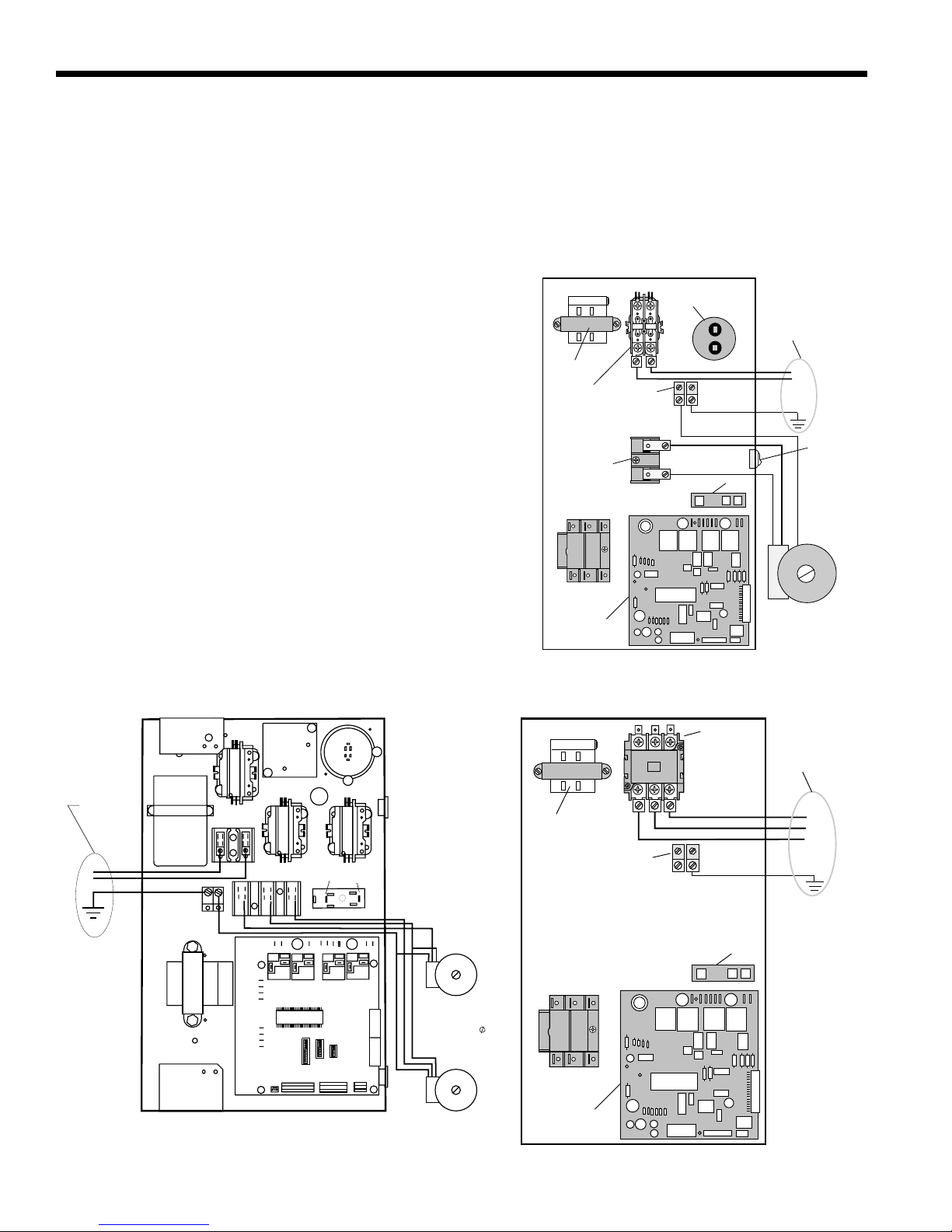
Compressor
Capacitor
Transformer
External Loop Pump(s)
208-230/60/1
1/2 HP Max
Voltage
Selection
Rocker Switch
PS
PB1
Ground
Lugs
Unit Control
Board
208-230/60/1
Service with
Ground
L1
L2
D
C
A
Compressor
Contactor
External Loop
Pumps
208-230v/60/1
1/2 H.P. Max
208-230v/60/1
Service with
Ground
Stage 1
D
Blk
Blu
C
B
A
START CAP
PB2
CCL
CCH
PB-1
TRANS
PCB
L1
L2
Stage 2
Transformer
PS
Ground
Lugs
Unit Control
Board
Three-phase Unit
Service with
Ground
L1
L2
D
C
A
L3
Compressor
Contactor
Electrical Connections
General
Be sure the available power is the same voltage and phase as that shown on the unit serial plate. Line and low voltage
wiring must be done in accordance with local codes or the National Electric Code, whichever is applicable.
Unit Power Connection
Connect the incoming line voltage wires to L1 and L2, or L1,L2, and
L3 of the contactor as shown in Figure 13 for single-phase unit and in
Figure 15 for three-phase units. All 460/60/3 units with an ECM fan
motor must pull a neutral wire to complete the unit wiring. Consult the
Unit Electrical Data in the Specification Catalog for correct fuse sizes.
Accessory Relay
A set of “dry” contacts has been provided to control accessory devices,
such as water solenoid valves on open loop installations, electronic air
cleaners, humidifiers, etc. This relay contact should be used only with
24 volt signals and not line voltage power. The relay has both normally
open and normally closed contacts and can operate with either the fan
or the compressor. Use DIP switch SW2-3 to cycle the relay with fan or
compressor. The relay contacts are available on terminals #2 and #3 of
P3.
208 Volt Operation
All E Series 208/230 units are factory wired for 230 volt operation. A
switch located on the control box, allows the installer to select 208 volt
unit operation. (Refer to Figure 13.)
Figure 14: Line Voltage 208-230/60/1 Control Box
(Dual Capacity Units)
Figure 13: Line Voltage 208-230/60/1 Control Box
(Single Speed Units)
Figure 15: Line Voltage Three Phase Control Box
(460 volt units with ECM blowers use power block.)
12
Page 13
Electronic Thermostat
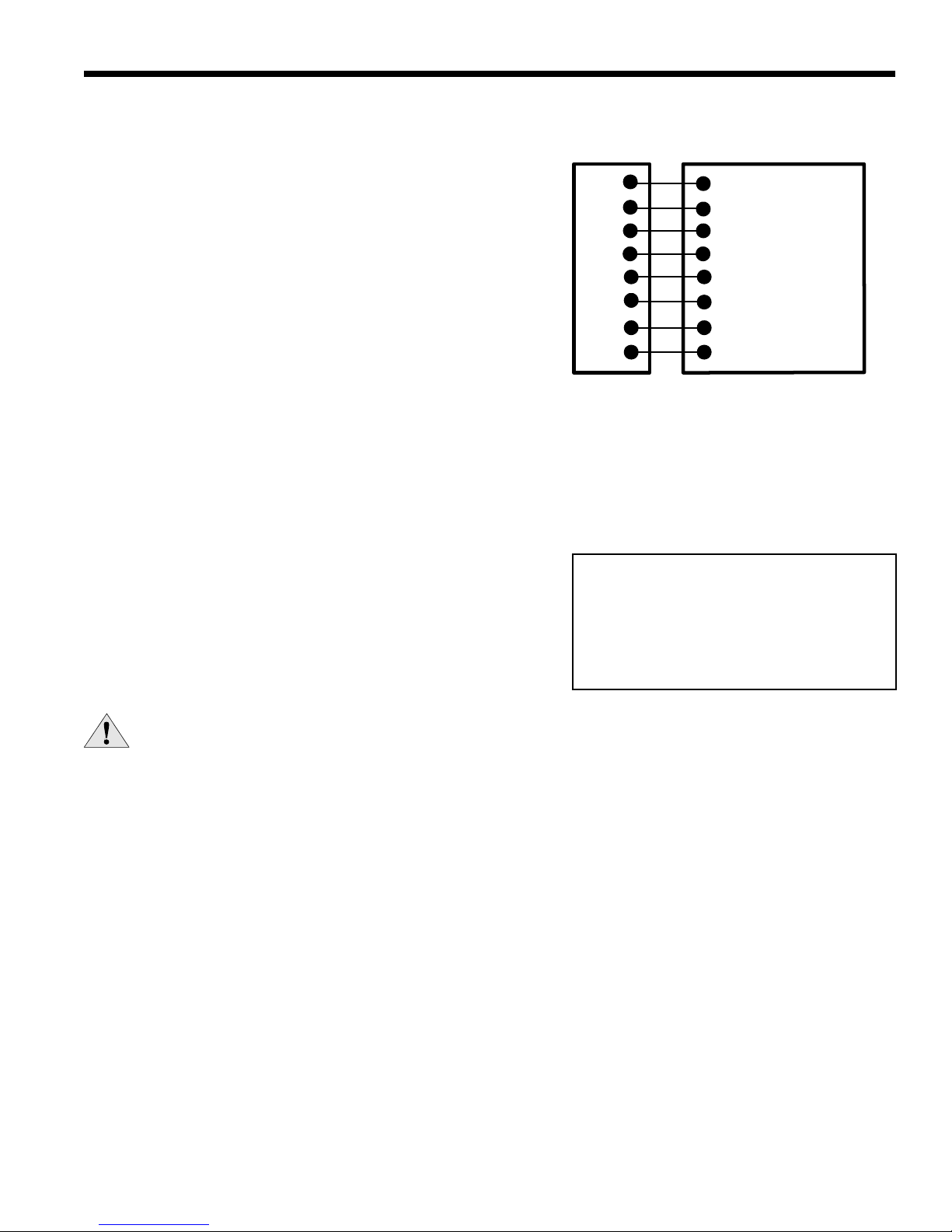
R
Y1
C
W
O
G
L
24VAC (Hot)
24VAC (Common)
Compressor (1st Stage)
Aux. Heat
Reversing Valve
Blower Relay
System Monitor
M
icroprocessor Controlle
r
Thermos
tat Connec
ti
on
Y2
Compressor (2nd Stage)
Position the thermostat subbase against the wall so that it is
level and the thermostat wires protrude through the middle of the
subbase. Mark the position of the subbase mounting holes and
drill holes with a 3/16-inch bit. Install supplied anchors and secure
base to the wall. Thermostat wire must be 8-conductor, 18-AWG
wire. Strip the wires back 1/4-inch (longer strip lengths may
cause shorts) and insert the thermostat wires into the connector
as shown. Tighten the screws to insure secure connections. The
thermostat has the same type connectors, requiring the same
wiring. See instructions enclosed in the thermostat for detailed
installation and operation information.
Note: DIP switch SW2- #8 is required to be in the OFF position
for the control to recognize the 24VAC thermostat inputs. The
second stage compressor wire must be installed between the
unit and the thermostat for proper control operation.
E SERIES INSTALLATION MANUAL
Figure 16: Thermostat Wiring
Setting Fan Speed
ECM2 fan motors have a 12-speed selector dip switch on the logic
board (SW1) and are factory set for optimum performance. To change
speeds, select the appropriate speeds on dip switch SW1. Consult the
ECM2 fan performance table on page 14 for specific airflow and switch
information.
PSC fan motors have 3 speeds. To change speeds, remove one of
the blower access panels. Change the position of the wire on the motor terminals to any other two speed terminals. Refer to Figure 17 for
changing speed on a 460 volt PSC fan motor.
CAUTION: Disconnect all power before performing this operation.
Figure 17: Speed Change - 460 Volt
PSC Fan Motor
High - L1 to white side of capacitor, L2 to H on
motor.
Med - L1 to white side of capacitor, L2 to M on
motor, orange wire to M1 on motor.
Low - L1 to white side of capacitor, L2 to L on
motor, Yellow wire to L1 on motor,
Orange to M1 on motor.
13
Page 14
E SERIES INSTALLATION MANUAL
1
2
3
4
5
6
7
8
9
10
11
12
SW1
OnOff
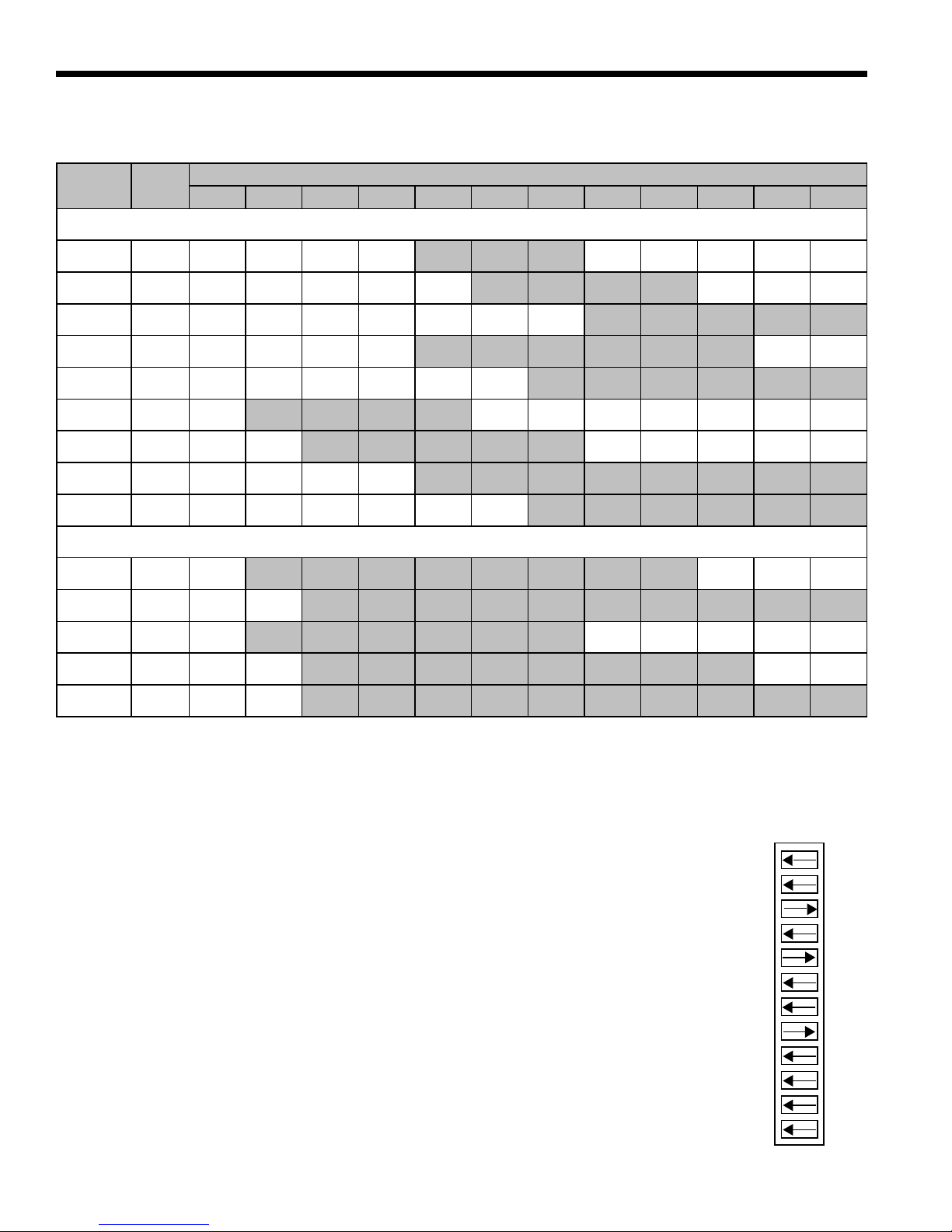
Fan Performance Data
ECM2
MODEL
SINGLE SPEED
E024 0.50 300 400
E030 0.50 300 400
E035 0.50 500 600
E040 0.50 650 750
E047 0.50 650 750 850 950
E040
w/ 1 HP*
E047
w/ 1 HP*
E058 0.75 750 900 1000
E066 0.75 750 900 1000 1200
DUAL CAPACITY
E036 0.50
E048 0.50
E048
w/ 1 HP*
E060 0.75
E072 0.75
Notes: * With optional 1 HP fan motor.
Factory settings are at recommended L-M-H DIP switch locations. M-H settings must be located within shaded CFM range. CFM is controlled
within ± 5% up to the maximum ESP. Max ESP includes allowance for wet coil and standard filter. Lowest and highest dip switch setting are assumed to be L and H speed, respectively.
MAX
ESP
0.75
0.75 800
0.75
800
600
600
750
750
750
1 2 3 4 5 6 7 8 9 10 11 12
850
L
1000
L
L
L
L
L
L
M
1000
700
700 800 900
900
900 1000
900 1000 1200
1100
1100
L
800
M
1000
M
AIR FLOW DIP SWITCH SETTINGS
500
L
500
L
950
1300
H
1300M1500
1200
L
900 1000 1100
1200 1400
1200
M
600
M
600
1050
M
1050
L
1500
H
1400
M
1400
L
1000
M
1400 1600 1700 1850
1400
M
700
L
700
M
700
L
1150 1250
1150
1600 1800
1600 1700
1600
1100 1200 1300 1400
1600
H
1600 1700 1850 2000
800
800
800
1250
1700
1200
1700 1850 2000 2200 2300 2400
900
900
1325
M
M
H
1325 1375 1475
1850
1850 2000
1300 1400 1500 1550 1600
1000
H
1000
M
1375 1475
H
2000 2200 2300 2400
H
2000
1100
H
2200
H
1500
H
2200 2300 2400
H
2200
H
1175 1250
1550
2300 2400
1550 1600
2300 2400
1600
H
A 12-position DIP switch package on the control allows the airflow levels to be set for low,
medium, and high speed when using the ECM2 blower motor. Only three of the DIP switches
can be in the "on" position.
The first "on" switch (the lowest position number) determines the low speed fan setting.
•
The second "on" switch determines the medium speed fan setting.
•
The third "on" switch determines the high speed fan setting.
•
The example to the right shows SW1 on the control board configured for the following E040
airflow settings.
Low Speed Fan: 850 CFM
Medium Speed Fan: 1050 CFM
High Speed Fan: 1325 CFM
14
Page 15
E SERIES INSTALLATION MANUAL
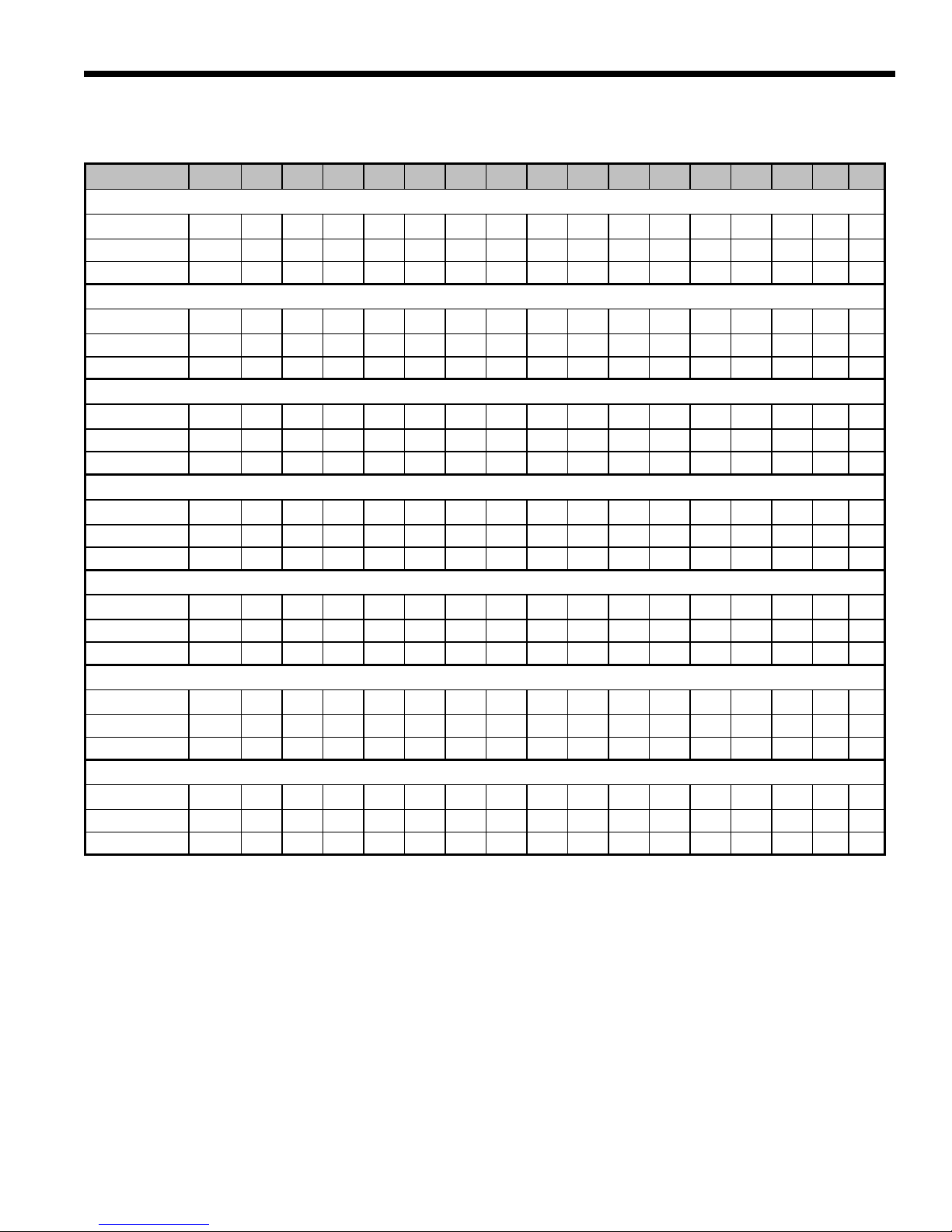
Fan Performance Data
PSC
SPEED 0.00 0.05 0.10 0.15 0.20 0.25 0.30 0.35 0.40 0.45 0.50 0.60 0.70 0.80 0.90 1.00
E024
Max 1020 CFM High* 1020 1003 984 961 940 908 882 845 810 772 717 653 - - - -
Rated 700 Med 801 795 784 776 761 742 714 692 672 628 580 - - - - -
Min 580 CFM Low 713 705 691 694 674 665 645 616 594 - - - - - - -
E030
Max 1275 CFM High* 1275 1252 1230 1210 1179 1152 1108 1079 1030 991 955 849 687 - - -
Rated 900 Med 1052 1042 1034 1027 1001 993 959 940 908 868 836 744 - - - -
Min 720 CFM Low 847 845 844 846 830 829 805 793 768 739 720 - - - - -
E035
Max 1420 CFM High* 1420 1391 1357 1329 1294 1254 1212 1167 1119 1067 1016 892 - - - -
Rated 1100
Min 890 CFM Low 1077 1070 1058 1046 1034 1006 974 953 925 890 - - - - - -
E040
Max 1610 CFM High* 1610 1588 1568 1536 1498 1469 1427 1388 1360 1293 1229 1128 - - - -
Rated 1300 Med 1397 1374 1360 1344 1302 1298 1269 1237 1189 1162 1105 - - - - -
Min1040 CFM Low 1100 1092 1081 1066 1055 1040 - - - - - - - - - -
E047
Max 1800 CFM High* - 1800 1760 1725 1690 1632 1584 1523 1474 1399 1308 1194 - - - -
Rated 1500 Med 1571 1547 1518 1486 1456 1414 1388 1331 1281 1236 1168 1080 - - - -
Min 1080 CFM Low 1183 1175 1162 1149 1136 1111 1085 - - - - - - - - -
E058
Max 2160 CFM High* - - - - - - 2160 2115 2057 2016 1963 1860 1722 - - -
Rated 2000 Med - - - 2141 2105 2072 2034 1994 1947 1907 1861 1774 1650 - - -
Min 1550 CFM Low 2071 2049 2026 2000 1970 1941 1908 1872 1834 1792 1749 1655 1550 - - -
E066
Max 2300 CFM High* - - - - - 2300 2237 2199 2135 2102 2037 1938 1789 1725 - -
Rated 2200 Med 2282 2249 2224 2198 2157 2134 2091 2056 1995 1964 1915 1817 1676 - - -
Min 1630 CFM Low 2059 2030 2008 1983 1942 1924 1877 1853 1812 1770 1730 1630 - - - -
Med 1214 1199 1185 1152 1127 1096 1056 1031 1002 956 908 - - - - -
Notes: All units tested with a wet coil and clean 1-inch filter. E030 265 volt units are shipped on medium speed.
* Indicates factory settings
15
Page 16

E SERIES INSTALLATION MANUAL
Standard Microprocessor Control Features
Startup
The unit will not operate until all the inputs and safety controls are checked for normal conditions. At first power-up, a
four-minute delay is employed before the compressor is energized.
Component Sequencing Delays
Components are sequenced and delayed for optimum space conditioning performance.
Accessory Relay
An accessory relay on the control board allows for field connection of solenoid valves, electronic air cleaners, etc. The
accessory relay has a normally open output and a normally closed output.
Short Cycle Protection
The control employs a minimum "off" time of four minutes to provide for short cycle protection of the compressor.
Condensate Overflow Protection
The E Series control board incorporates an impedance sensing liquid sensor at the top of the drain pan. Upon a continuous 30-second sensing of the condensate, compressor operation is suspended (see Fault Retry), and the condensate
overflow lockout LED begins flashing.
Shutdown Mode
A 24VAC common signal to the “shutdown” input on the control board puts the unit into shutdown mode. Compressor,
hot water pump and fan operation are suspended.
Safety Controls
The E Series control receives separate signals for a high pressure switch for safety, a low pressure switch to prevent
loss of charge damage, and a low suction temperature thermistor for freeze protection. Upon a continuous 30-second
measurement of the fault (immediate for high pressure), compressor operation is suspended, the appropriate lockout LED
begins flashing. (Refer to the "Fault Retry" section below.)
Testing
The E Series control allows service personnel to shorten most timing delays for faster diagnostics. (Refer to the Field
Selection DIP switch SW2-1 on page 18.)
Fault Retry
All faults (except for low RPM faults with the ECM2 fan motor) are retried twice before finally locking the unit out. An
output signal is made available for a fault LED at the thermostat. The “fault retry” feature is designed to prevent nuisance
service calls.
Diagnostics
The E Series control board allows all inputs and outputs to be displayed on the LEDs for fast and simple control board
diagnosis. (Refer to the Field Selection DIP Switch SW2-1 on page 18.)
Resistance Heat Control
(208-230 Units)
The electric heat control module contains the appropriate high-voltage control relays. Control signals energize the relays
in the proper sequence, and the LED display board indicates which stages are energized.
Hot Water High Limit
(Domestic Hot Water Option)
This mode occurs when the hot water input temperature is at or above 130°F for 30 continuous seconds. The DHW limit
status LED on the unit illuminates and the hot water pump de-energizes. Hot water pump operations resume on the next
compressor cycle or after 30 minutes of continuous compressor operation during the current thermostat demand cycle.
16
Page 17

E SERIES INSTALLATION MANUAL
Standard Microprocessor Control Features
Fan Speed Control
A DIP switch on the E Series control allows field selection of 15% reduced fan speeds for cooling in the dehumidification
mode or medium and high fan speeds for cooling in the normal mode.
Note: Fan speed can change automatically only with an ECM Motor.
ECM2 Airflow Selection DIP Switches (SW1)
A 12-position DIP switch package on the E Series control allows the airflow levels to be set for low, medium and high
speed. (Refer to the ECM Blower Table on page 14.)
Only three of the DIP switches can be in the “on” position. The first “on” switch (the lowest position number) determines
the “low speed fan” setting. The second “on” switch determines the “medium speed fan” setting, and the third “on” switch
determines the “high speed fan” setting, (see page 14).
17
Page 18
E SERIES INSTALLATION MANUAL
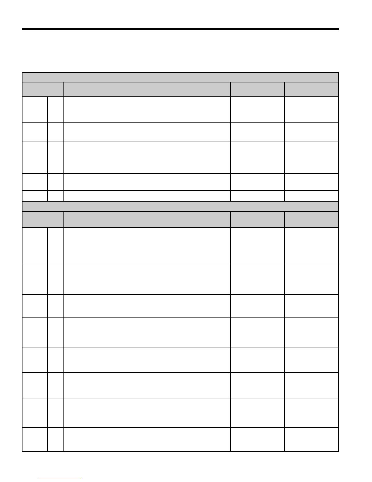
Standard Microprocessor DIP Switches
Prior to powering unit, ensure that all DIP switches on SW2 & SW3 are set properly according to the tables below.
FACTORY SETUP DIP SWITCHES (SW3)
DIP SWITCH
NUMBER
SW 3- 1
Dual Capacity/Single-Speed
Configures the control for single-speed compressor operation or
dual capacity operation.
DESCRIPTION OFF POSITION ON POSITION
Dual Capacity
Operation
Single-Speed
Operation
SW 3- 2
SW 3- 3
SW 3- 4
SW 3- 5 Future Use Future Use Future Use
DIP SWITCH
NUMBER
SW 2- 1
SW 2- 2
SW 2- 3
SW 2- 4
SW 2- 5
ECM2
Must be in the “ON” position.
No RPM/RPM
Configures the control to monitor the RPM output of an ECM/
ECM2 blower motor. When using IntelliZone or a PSC fan motor,
the control should be configured for “NO RPM” sensing.
Electric heat
Must be in the “ON” position to engage auxiliary heat.
FIELD SELECTION DIP SWITCHES (SW2)
DESCRIPTION OFF POSITION ON POSITION
Service Test Mode
On the control, allows field selection of “NORMAL” or “TEST” operational modes. Test mode accelerates most timing functions 16
times to allow faster troubleshooting. Test mode also allows view
ing the “CURRENT” status of the fault inputs on the LED display.
Freeze Protection Setting
Allows field selection of freeze thermistor fault sensing tempera
tures for well water (30°F) or antifreeze-protected (15°F) earth
loops.
Accessory Relay
Allows field selection of the accessory relay to operate with the
compressor or fan.
Fan Speed Control
Allows field selection of reduced fan speed (85% of selected
medium and high speed – ECM only) for cooling in the dehumidification mode.
Auxiliary Off
Disables 3rd-stage Heating. Full emergency heat would still be
available if needed.
-
Does Not Apply
PSC Fan/RPM
Monitoring Disabled
No Aux Heat
Test Mode
-
Loop Water
Freeze Protection
15° F
Acc Relay Tracks
Fan
Dehumidification
Fan Speeds
Disable Heating
Stage 3
Normal
ECM-ECM2 Fan/
RPM Monitoring
Enabled
Normal
Normal Speed
Operation
Well Water
Freeze Protection
30° F
Acc Relay Tracks
Compressor
Normal Fan
Speeds
Enable Heating
Stage 3
Diagnostics Inputs
SW 2- 6
SW 2- 7
SW 2- 8
Allows viewing the inputs from the thermostat to the control board
such as Y1, Y2, O, G, W, SL1-In on the LED display.
Diagnostics Outputs
Allows viewing the outputs from the control board such as compressor, reversing valve, blower, hot water pump, and loop pump
on the LED display.
Thermostat Selection
Allows field selection of the type of thermostat being connected to
the control. The DIP switch should be in the OFF position.
18
Diagnostic Inputs
Viewed at LEDs
Diagnostic Outputs Viewed at
LEDs
24 VAC
Thermostats
Normal Display
Viewed at LEDs
Normal Display
Viewed at LEDs
TA32E12
Thermostat
Page 19
E SERIES INSTALLATION MANUAL
Optional FX10 Microprocessor Control
The Johnson Controls FX10 board is specifically designed for commercial heat pumps and provides control of the entire unit
as well as input ports for N2 Open, LonTalk, BacNet communication protocols as well as an input port for a user interface.
The user interface is an accessory item that can be used to aid in diagnostics and unit setup. A 16 pin low voltage terminal
board provides terminals for common field connections.
FX10 Operation
Startup
•
The unit will not operate until all the inputs and safety controls are checked for normal operating conditions.
Fault Retry
•
All faults are tested twice before finally locking the unit out to prevent nuisance service calls.
Component Sequencing Delays
•
Components are sequenced and delayed for optimum unit performance. See table below.
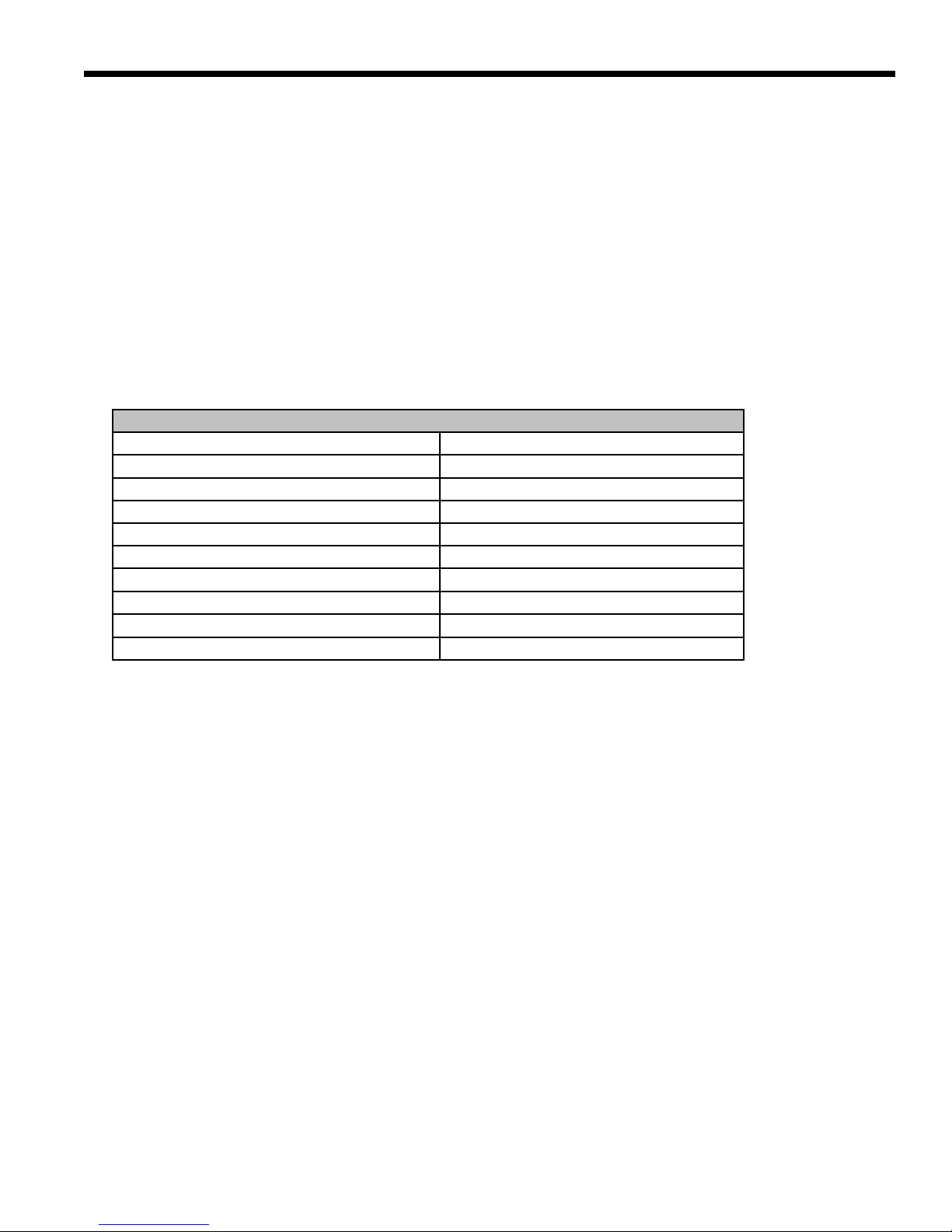
CONTROL TIMING
Lead compressor ON delay 30 seconds
Short cycle delay 4 minutes
Minimum compressor ON time 2 minutes (except for fault condition)
High pressure fault recognition Less than 1 second
Low pressure fault recognition delay 30 seconds
Freeze protection fault recognition delay 30 seconds
Condensate overflow fault recognition delay
Low pressure fault bypass delay 2 minutes
Freeze protection fault bypass delay 2 minutes
Random start delay 0-120 seconds
30 seconds
Short Cycle Protection
•
The control allows a minimum compressor off time of 4 minutes and a minimum compressor run time of 2 minutes for
short cycle protection.
Random Start
•
A random start delay of 1 to 120 seconds is generated after each power up to prevent simultaneous startup of all units
within a building after the release from an unoccupied cycle or power loss.
Emergency Shutdown
•
A normally open dry contact must be placed between DI2 and PB2-L2. Closing the contact will set the unit into emer gency shutdown mode. All unit operation is suspended while in emergency shutdown mode.
Condensate Overflow Protection
•
The board incorporates an impedance liquid sensor at the top of the condensate drain pan. Upon a continuous 30-
second sensing of the condensate, the operation of the unit is suspended.
Safety Controls
•
The FX10 board receives separate signals from a high pressure switch for safety, a low pressure switch to detect loss
of refrigerant charge and a low suction temperature thermistor for freeze protection. Upon a continuous 30-second
measurement of the fault (immediate for high pressure), compressor operation is stopped.
•
Freeze Protection
Note: For applications using a closed loop antifreeze solution, remove the wire between DI5 and PB2-L1 (see unit
schematic). On applications using an open loop/ground water system, make sure the wire is connected.
Note: For additional information on the FX10 Control, refer to Application Guide AGFX10 or Submittal Data SD1981.
19
Page 20

E SERIES INSTALLATION MANUAL
Unit Startup
Before Powering Unit, Check The Following:
High voltage is correct and matches nameplate.
•
Fuses, breakers and wire size correct.
•
Low voltage wiring complete.
•
Piping completed and water system cleaned and flushed.
•
Air is purged from closed loop system.
•
Isolation valves are open, water control valves or loop pumps wired.
•
Condensate line open and correctly pitched.
•
Transformer switched to 208V if applicable.
•
Black/white and gray/white wires in unit control box have been removed if auxiliary heat has been installed.
•
Dip switches are set correctly.
•
DHW pump switch is “OFF” unless piping is completed and air has been purged.
•
Blower rotates freely – foam shipping support has been removed.
•
Blower speed correct (dip switch is set correctly).
•
Air filter/cleaner is clean and in position.
•
Service/access panels are in place.
•
Return air temperature is between 50-80ºF heating and 60-95ºF cooling.
•
Check air coil cleanliness to insure optimum performance. Clean as needed according to maintenance guidelines.
•
To obtain maximum performance the air coil should be cleaned before startup. A 10-percent solution of dishwasher
detergent and water is recommended for both sides of coil, a thorough water rinse should follow.
Startup Steps
Note: Complete the Equipment Start-Up/Commissioning Check Sheet during this procedure. Refer to thermostat
operating instructions and complete the startup procedure.
1. Initiate a control signal to energize the blower motor. Check blower operation.
2. Initiate a control signal to place the unit in the cooling mode. Cooling setpoint must be set below room temperature.
3. First stage cooling will energize after a time delay.
4. Be sure that the compressor and water control valve or loop pump(s) are activated.
5. Verify that the water flow rate is correct by measuring the pressure drop through the heat exchanger using the P/T
plugs and comparing to unit capacity data in specification catalog.
6. Check the temperature of both the supply and discharge water (see page 23-24).
7. Check for an air temperature drop of 15°F to 25°F across the air coil, depending on the fan speed and entering water
temperature.
8. Decrease the cooling set point several degrees and verify high-speed blower operation.
9. Adjust the cooling setpoint above the room temperature and verify that the compressor and water valve or loop pumps
deactivate.
10. Initiate a control signal to place the unit in the heating mode. Heating set point must be set above room temperature.
11. First stage heating will energize after a time delay.
12. Check the temperature of both the supply and discharge water (see page 23-24).
13. Check for an air temperature rise of 20°F to 35°F across the air coil, depending on the fan speed and entering water
temperature.
14. If auxiliary electric heaters are installed, increase the heating setpoint until the electric heat banks are sequenced on.
All stages of the auxiliary heater should be sequenced on when the thermostat is in the Emergency Heat mode.
Check amperage of each element.
15. Adjust the heating setpoint below room temperature and verify that the compressor and water valve or loop pumps
deactivate.
16. During all testing, check for excessive vibration, noise or water leaks. Correct or repair as required.
17. Set system to desired normal operating mode and set temperature to maintain desired comfort level.
18. Instruct the owner/operator in the proper operation of the thermostat and system maintenance.
Note: Be certain to fill out and forward all warranty registration papers.
20
Page 21

E SERIES INSTALLATION MANUAL
Description of Unit Operation
Heating Operation
Heat, 1st Stage (Y1)
The fan motor is started on low speed immediately, the loop pump is energized 5 seconds after the “Y1” input is received, and the compressor is energized on low capacity 10 seconds after the “Y1” input. The fan is switched to medium
speed 15 seconds after “Y1” input. The hot water pump is cycled 30 seconds after the “Y1” input.
Heat, 2nd Stage (Y1, Y2) Single Speed Units
The hot water pump is de-energized, which directs all heat to satisfying the thermostat, and the fan changes to high
speed 15 seconds after the “Y2”input.
Heat, 2nd Stage (Y1, Y2) Dual Capacity Units
The compressor is de-energized immediately, the second loop pump is energized 5 seconds after the “Y2” input, and
the hot water pump is cycled 30 seconds after the “Y2” input. The fan changes to high speed 45 seconds after the “Y2”
input and the compressor is energized on high capacity 60 seconds after the “Y2” input.
Heat, 3rd Stage (Y1, Y2, W) Single Speed Units
The first stage of resistance heat is energized 10 seconds after “W” input, and with continuous 3rd stage demand, the
additional stages of resistance heat engage sequentially every 5 minutes.
Heat, 3rd Stage (Y1, Y2, W) Dual Capacity Units
The hot water pump is de-energized which directs all heat to satisfy the thermostat. The 1st stage of resistance heat
is energized 10 seconds after “W” input, and with continuous 3rd stage demand, the additional stages of resistance heat
engage sequentially every 5 minutes.
Emergency Heat
The fan is started on high speed, and the first stage of resistance heat is energized 10 seconds after the “W” input.
Continuing demand will engage the additional stages of resistance heat sequentially every 2 minutes.
Cooling Operation
In all cooling operations, the reversing valve directly tracks the “O” input. Thus, anytime the “O” input is present, the
reversing valve will be energized.
Cool, 1st Stage (Y1,O)
The fan motor is started on low speed immediately, the loop pump is energized 5 seconds after the “Y1” input is received, and the compressor is energized 10 seconds after the “Y1” input. The fan is switched to medium speed 15 seconds
after “Y1” input (85% of medium speed if in dehumidification mode). The hot water pump is cycled 30 seconds after the
“Y1”input.
Cool, 2nd Stage (Y1, Y2, O) Single Speed Units
The fan changes to high speed (85% of high speed if in dehumidification mode) 15 seconds after the “Y2” input.
Cool, 2nd Stage (Y1, Y2, O) Dual Capacity Units
The compressor is de-energized immediately, the second loop pump is energized 5 seconds after the “Y2” input, and the
hot water pump is cycled 30 seconds after the “Y2” input. The fan changes to high speed (85% of high speed if in dehumidi
fication mode) 45 seconds after the “Y2” input and the compressor is energized on high capacity 60 seconds after the “Y2”
input.
Fan(G only)
The fan starts on low speed. Regardless of fan input “G” from thermostat, the fan will remain on low speed for 30
seconds at the end of each heating, cooling or emergency heat cycle.
Lockout Conditions
During lockout mode, the appropriate unit and thermostat lockout LEDs will illuminate. The compressor, loop pump, hot
water pump, and accessory outputs are de-energized. Unless the lockout is caused by an ECM2 low RPM fault, the fan will
continue to run on low speed. If the thermostat calls for heating, emergency heat operation will occur.
Lockout modes of any kind can be reset at the thermostat after a 5-second waiting period, which restores normal
operation but keeeps the unit lockout LED illuminated. Interruption of power to the unit will reset a lockout without a waiting
period and clear all lockout LEDs.
-
21
Page 22
E SERIES INSTALLATION MANUAL
Lockout Conditions (continued)
High Pressure
This lockout mode occurs when the normally closed safety switch is opened momentarily (set at 600 PSI).
Low Pressure
This lockout mode occurs when the normally closed low pressure switch is opened for 30 continuous seconds (set at
40 PSI). A low pressure fault may also be indicated when the current sensor is activated by a failure in the compressor
startup.
Freeze Protection (Water Flow)
This lockout mode occurs when the freeze thermistor temperature is at or below the selected freeze protection point
(well 30°F or loop 15°F) for 30 continuous seconds.
Condensate Overflow
This lockout mode occurs when the condensate overflow level has been reached for 30 continuous seconds.
Fan RPM
The control board monitors fan RPM to sense operation. This lockout mode occurs if the fan RPM falls below the low
RPM limit (100 RPM) for 30 continuous seconds.
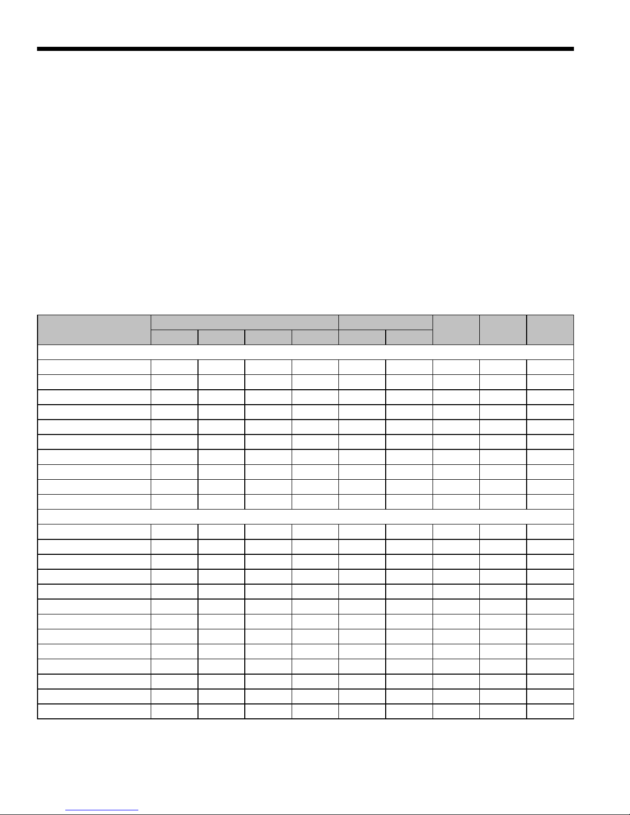
Operation Logic Data
OPERATION LOGIC
SINGLE SPEED UNITS
Compressor On On On Off On On
ECM2 Normal Med High High High Med High Low
ECM2 Dehumidify Med High High High 85% Med 85% High Low
Rev Valve Off Off Off Off On On
Loop Pump On On On Off On On
DHW Pump On Off Off Off On On
Aux Heater Off Off Staged Staged Off Off
Secondary 1- Out On On On Off On On
Emerg LED Off Off Off On Off Off Off
T-Stat Signal Y1 Y1, Y2 Y1, Y2, W
DUAL CAPACITY UNITS
Compressor-Lo On Off Off Off On Off
Compressor-Hi Off On On Off Off On
ECM2 Normal Med High High High Med High Low
ECM2 Dehumidify Med High High High 85% Med 85% High Low
Rev Valve Off Off Off Off On On
Loop Pump-Stg 1 On On On Off On On
Loop Pump-Stg 2 Off On On Off Off On
DHW Pump On On Off Off On On
Aux Heater Off Off Staged Staged Off Off
Secondary 1- Out On On On Off On On
Secondary 2- Out Off On On Off Off On
Emerg LED Off Off Off On Off Off
T-Stat Signal Y1 Y1, Y2 Y1, Y2, W
STG1 STG2 STG3 EMERG STG1 STG2
HEATING COOLING
W Y1, O Y1, Y2, O G - -
W Y1, O Y1, Y2, O G - -
FAN ON
- - -
- - -
- On -
- - -
- - -
- - -
- - -
- - -
- - -
- On -
- - On
- - -
- - -
- - -
- - -
- - -
SL1 - IN ONSL2 - IN
ON
- -
- -
- -
- -
- -
22
Page 23
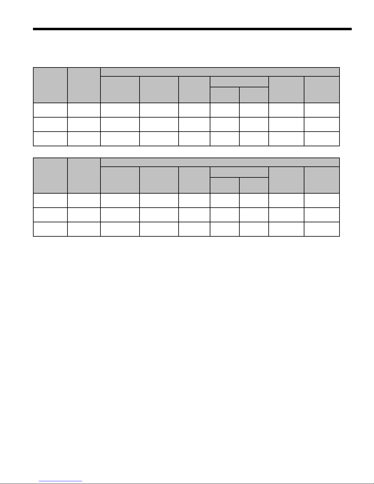
Unit Operating Parameters
Single Speed Models
COOLING - NO DESUPERHEATER
ENTERING
WATER
TEMP °F
WATER
FLOW
GPM/TON
SUCTION
PRESSURE
PSIG
DISCHARGE
PRESSURE
PSIG
SUPER
HEAT
024- 058
024- 058 066
SUBCOOLING
E SERIES INSTALLATION MANUAL
WATER
TEMP
RISE °F
AIR TEMP
DROP °F
DB
50 1.5
70 1.5
90 1.5
ENTERING
WATER
TEMP °F
30 1.5
50 1.5
70 1.5
3.0
3.0
3.0
WATER
FLOW
GPM/TON
3.0
3.0
3.0
122-130
120-128
127-136
125-134
132-144
130-142
SUCTION
PRESSURE
PSIG
68-76
72-80
100-110
104-114
134-144
138-148
220-235
190-210
280-300
250-270
360-380
330-350
DISCHARGE
PRESSURE
PSIG
285-310
290-315
315-345
320-350
355-395
360-390
13-19
13-19
11-15
11-15
10-14
10-14
HEATING - NO DESUPERHEATER
SUPER
HEAT
024- 058
8-12
8-12
9-13
9-13
10-14
10-14
10-16
10-16
8-14
8-14
8-14
8-14
SUBCOOLING
024- 058 066
3-9
3-9
5-11
5-11
6-12
6-12
10-16
10-16
10-16
10-16
10-16
10-16
18-22
18-22
22-26
22-26
24-28
24-28
19-23
9-12
19-23
9-12
18-22
9-12
WATER
TEMP
DROP °F
5-7
3-5
7-9
5-7
9-11
7-9
21-25
21-25
20-24
20-24
18-22
18-22
AIR TEMP
RISE °F
DB
15-21
17-23
22-28
24-30
30-36
32-38
23
Page 24
E SERIES INSTALLATION MANUAL
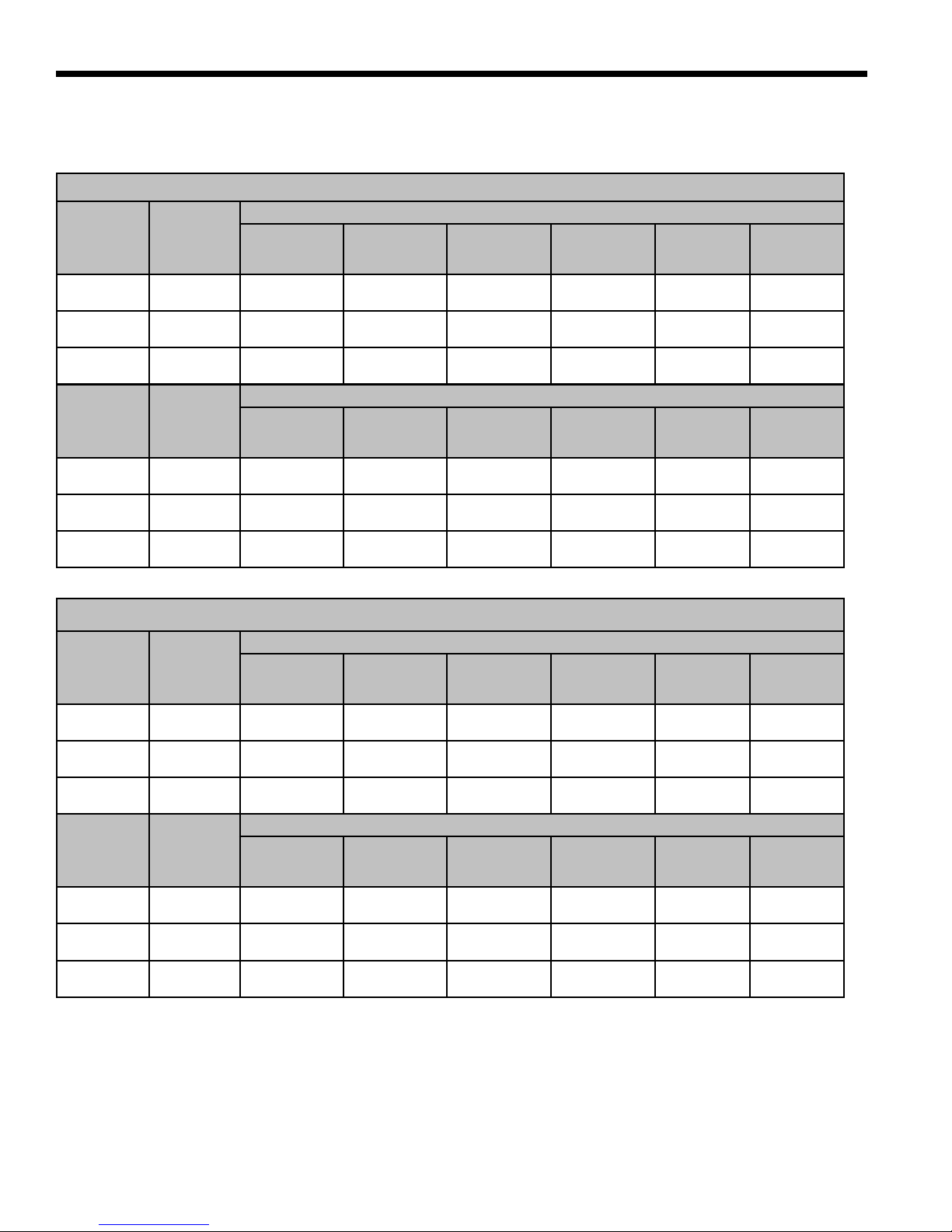
Dual Capacity Models
FIRST STAGE OPERATION
ENTERING
WATER
TEMP °F
50 1.5
70 1.5
90 1.5
ENTERING
WATER
TEMP °F
30 1.5
50 1.5
70 1.5
WATER
FLOW
GPM/TON
3.0
3.0
3.0
WATER
FLOW
GPM/TON
3.0
3.0
3.0
SUCTION
PRESSURE
134-144
132-142
142-150
140-148
148-155
146-153
SUCTION
PRESSURE
112-120
116-124
156-166
160-170
PSIG
PSIG
76-84
80-88
DISCHARGE
PRESSURE
PSIG
195-203
180-186
257-264
242-249
335-345
320-330
DISCHARGE
PRESSURE
PSIG
269-282
274-287
295-315
300-320
325-350
330-355
COOLING - NO DESUPERHEATER
SUPER
HEAT
14-20
14-20
12-16
12-16
10-14
10-14
HEATING - NO DESUPERHEATER
SUPER
HEAT
8-12
8-12
8-12
8-12
8-12
8-12
SUB
COOLING
12-18
12-18
12-18
12-18
12-18
12-18
SUB
COOLING
2-8
2-8
2-10
2-10
4-12
4-12
WATER
TEMP
RISE °F
21-25
10-15
20-24
9-13
18-22
8-12
WATER
TEMP
DROP °F
4-6
2-4
6-8
4-6
7-9
5-7
AIR TEMP
DROP °F
DB
21-25
21-25
20-24
20-24
18-22
18-22
AIR TEMP
RISE °F
DB
12-16
14-18
18-22
20-24
26-30
28-32
SECOND STAGE OPERATION
ENTERING
WATER
TEMP °F
50 1.5
70 1.5
90 1.5
ENTERING
WATER
TEMP °F
30 1.5
50 1.5
70 1.5
WATER
FLOW
GPM/TON
3.0
3.0
3.0
WATER
FLOW
GPM/TON
3.0
3.0
3.0
SUCTION
PRESSURE
PSIG
117-123
115-121
124-132
122-130
132-140
130-138
SUCTION
PRESSURE
PSIG
64-72
68-76
91-104
95-108
131-146
135-150
DISCHARGE
PRESSURE
PSIG
225-240
195-215
290-310
260-280
380-410
350-380
DISCHARGE
PRESSURE
PSIG
285-320
290-325
320-355
325-360
365-400
370-405
COOLING - NO DESUPERHEATER
SUPER
HEAT
14-20
14-20
12-16
12-16
10-14
10-14
HEATING - NO DESUPERHEATER
SUPER
HEAT
11-16
11-16
9-14
9-14
8-13
8-13
SUB
COOLING
10-16
10-16
10-16
10-16
10-16
10-16
SUB
COOLING
13-19
13-19
18-24
18-24
18-24
18-24
WATER
TEMP
RISE °F
20-24
10-14
19-23
9-13
18-22
8-12
WATER
TEMP
DROP °F
5-7
3-5
6-8
4-6
9-11
7-9
AIR TEMP
DROP °F
DB
21-25
21-25
20-24
20-24
18-22
18-22
AIR TEMP
RISE °F
DB
15-21
17-23
22-28
24-30
30-36
32-38
24
Page 25
E SERIES INSTALLATION MANUAL
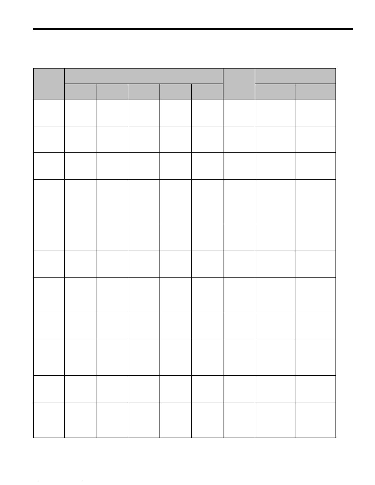
Pressure Drop & Recommended Flow Rates
PRESSURE DROP
(PSI CHANGE THROUGH HEAT EXCHANGER AT EWT ºF)
UNIT
E024 1.4 1.4 1.4 1.3 1.3 4.5 4.5 - 6
E030 2.4 2.2 2.1 2.0 2.0 5.5 5.5 - 7
E035 3.6 3.4 3.2 3.1 3.0 7.0
E036 1.6 1.5 1.4 1.3 1.2 5.0 7 - 9 Hi cap 5 - 7 Hi cap
E040 3.5 3.3 3.3 3.1 3.0 8.0 8 - 11
E047 3.7 3.5 3.3 3.3 3.0 9.0 9 - 12
E048
E058 3.1 2.9 2.8 2.7 2.6 11.0 11 - 14
E060
E066 4.3 4.1 3.8 3.6 3.4 13.0 13 - 16 10 - 11
E072
30° 50° 70° 90° 110°
0.7 0.7 0.7 0.6 0.6 3.0
2.4 2.4 2.4 2.3 2.2 6.0
1.4 1.3 1.2 1.2 1.1 4.0
3.6 3.4 3.2 3.1 3.0 7.0
2.2 2.1 1.9 1.8 1.8 5.0
5.7 5.4 5.0 4.8 4.7 9.0
0.7 0.6 0.5 0.4 0.3 3.0
1.1 1.0 0.8 0.7 0.6 4.0 4 - 5 Lo cap 3 - 4 Lo cap
2.9 2.8 2.6 2.5 2.3 7.0
4.7 4.5 4.2 4.0 3.7 9.0
1.7 1.6 1.6 1.5 1.5 5.0
4.9 4.7 4.7 4.4 4.3 11.0
2.0 1.9 1.8 1.7 1.6 6.0
5.9 5.6 5.3 5.2 4.8 12.0
0.4 0.4 0.4 0.4 0.4 3.0
1.8 1.7 1.6 1.5 1.4 6.0 6 - 9 Lo cap 3 - 6 Lo cap
3.3 3.2 3.0 2.9 2.8 9.0 9 - 12 Hi cap 6 - 9 Hi cap
5.3 5.1 4.8 4.7 4.5 12.0
2.1 2.0 2.0 1.9 1.8 8.0
5.5 4.6 4.0 4.2 4.1 14.0
1.1 1.0 0.9 0.9 0.9 5.0
2.1 2.0 2.0 1.9 1.8 8.0 8 - 11 Lo cap 5 - 8 Lo cap
3.1 2.9 2.8 2.7 2.6 11.0 11 - 14 Hi cap 8 - 11 Hi cap
4.8 4.6 4.4 4.2 3.9 14.0
2.7 2.6 2.4 2.3 2.2 10.0
6.1 5.8 5.4 5.1 4.8 16.0
1.5 1.4 1.3 1.2 1.1 7.0
2.7 2.6 2.4 2.3 2.2 10.0 10 - 13 Lo cap 7 - 10 Lo cap
4.3 4.1 3.8 3.6 3.4 13.0 13 - 16 Hi cap 10 - 13 Hi cap
6.1 5.8 5.4 5.1 4.8 16.0
GPM
RECOMMENDED
FLOW RATE (GPM)
CLOSED
LOOP
7 - 9 5 - 6
WELL
WATER
3 - 4
4 - 5
5 - 6
6 - 7
8 - 9
25
Page 26
E SERIES INSTALLATION MANUAL
Troubleshooting
Standard Microprocessor Controls
To check the unit control board for proper operation:
1) Disconnect thermostat wires at the control board.
2) Jumper the desired test input (Y1, Y2, W, O or G) to the R terminal with the SW2-8 in the “OFF” position to simulate
a thermostat signal.
3) If control functions properly:
• Check for thermostat and field control wiring (use the diagnostic inputs mode).
4) If control responds improperly:
• Ensure that component being controlled is functioning (compressor, blower, reversing valve, etc.).
• Ensure that wiring from control to the component is functioning (refer to the LED Definition table below and use the
diagnostic outputs mode).
• If steps above check properly, replace unit control.
LED Definitions and Diagnostics
Standard Microprocessor
LED
Drain
Water Flow
High
Pressure
Low
Pressure
Airflow
Status
DHW Limit
DHW Off
NORMAL
DISPLAY MODE
Field Selection DIPS
SW2- 1 On SW2- 1 Off SW2- 1 NA SW2- 1 NA SW2- 1 NA
SW2- 6 On SW2- 6 On SW2- 6 Off SW2- 6 On SW2- 6 Off
SW2- 7 On SW2- 7 On SW2- 7 On SW2- 7 Off SW2- 7 Off
Drain Pan Overflow
Lockout
FP Thermistor (Loop
<15º F, Well<30ºF)
Lockout
High Pressure >600
PSI Lockout
Low Pressure <40
PSI Lockout
ECM2 RPM <100
RPM
Microprocessor
Malfunction
HWL Thermistor
>130º
DHW Pump
Switch Off
F
CURRENT
FAULT STATUS
Drain Pan Overflow Y1
FP Thermistor (Loop
<15º F, Well<30ºF)
High Pressure >600
Low Pressure <40
ECM2 RPM
<100 RPM
Not Used SL1 Loop Pump 1 Aux Heat 3
HWL Thermistor
>130°F
DHW Pump
Switch Off
DIAGNOSTIC MODES
INPUTS OUTPUTS 1 OUTPUTS 2
Compressor
(On or Low)
Y2
O Reversing Valve
G Fan Aux Heat 1
W DHW Pump Aux Heat 2
Not Used Loop Pump 2 Aux Heat 4
– – –
Compressor
(On or High)
Blower
Low
Blower
Medium
Blower
High
Refrigerant Systems
To maintain sealed circuit integrity, do not install service gauges unless unit operation appears abnormal. Compare the
change in temperature on the air side as well as the water side to the tables on pages 23-24. If the unit’s performance is not
within the ranges listed, and the airflow and water flow are known to be correct, gauges should then be installed and superheat and subcooling numbers calculated. If superheat and subcooling are outside recommended ranges, an adjustment to
the refrigerant charge may be necessary.
Note:
Refrigerant tests must be made with desuperheater turned “OFF”.
levels before servicing the refrigerant circuit.
Verify that air and water flow rates are at proper
26
Page 27
E SERIES INSTALLATION MANUAL
Preventive Maintenance
Water Coil Maintenance
1. Keep all air out of the water. An open loop system should be checked to ensure that the well head is not allowing air to
infiltrate the water line. Lines should always be airtight.
2. Keep the system under pressure at all times. It is recommended in open loop systems that the water control valve be
placed in the discharge line to prevent loss of pressure during off cycles. Closed loop systems must have positive static
pressure.
Note: On open loop systems, if the installation is in an area with a known high mineral content (125 PPM or greater) in the
water, it is best to establish with the owner a periodic maintenance schedule so the coil can be checked regularly. Should
periodic coil cleaning be necessary, use standard coil cleaning procedures which are compatible with either the cupronickel
or copper water lines. Generally, the more water flowing through the unit the less chance for scaling.
Other Maintenance
Filters
Filters must be clean to obtain maximum performance. They should be inspected monthly under normal operating condi-
tions and be replaced when necessary. Units should never be operated without a filter.
Condensate Drain
In areas where airborne bacteria produce a slime in the drain pan, it may be necessary to treat chemically to minimize
the problem. The condensate drain can pick up lint and dirt, especially with dirty filters. Inspect twice a year to avoid the
possibility of overflow.
Blower Motors
Blower motors are equipped with sealed ball bearings and require no periodic oiling.
Desuperheater Coil
See Water Coil Maintenance section above.
Air Coil
The air coil must be cleaned to obtain maximum performance. Check once a year under normal operating conditions
and, if dirty, brush or vacuum clean. Care must be taken not to damage the aluminum fins while cleaning.
CAUTION: Fin edges are sharp.
Replacement Procedures
Obtaining Parts
When ordering service or replacement parts, refer to the model number and serial number of the unit as stamped on the
serial plate attached to the unit. If replacement parts are required, mention the date of installation of the unit and the date of
failure, along with an explanation of the malfunctions and a description of the replacement parts required.
In-Warranty Material Return
Material may not be returned except by permission of authorized warranty personnel. Contact your local distributor for
warranty return authorization and assistance.
27
Page 28

Manufactured by WFI
9000 Conservation Way
Fort Wayne, IN 46809
WFI has a policy of continuous product research and
development and reserves the right to change design
and specifications without notice.
©2004 WFI.
Product: E Series
Type: Geothermal/Water Source Heat Pumps
Size: 2 thru 6 Ton
Document Type: Installation Manual
Part Number: IM2502
Release Date: 09/04
Supercedes: IM1461 (06/04), IM2500 (07/04)
 Loading...