

Page 1
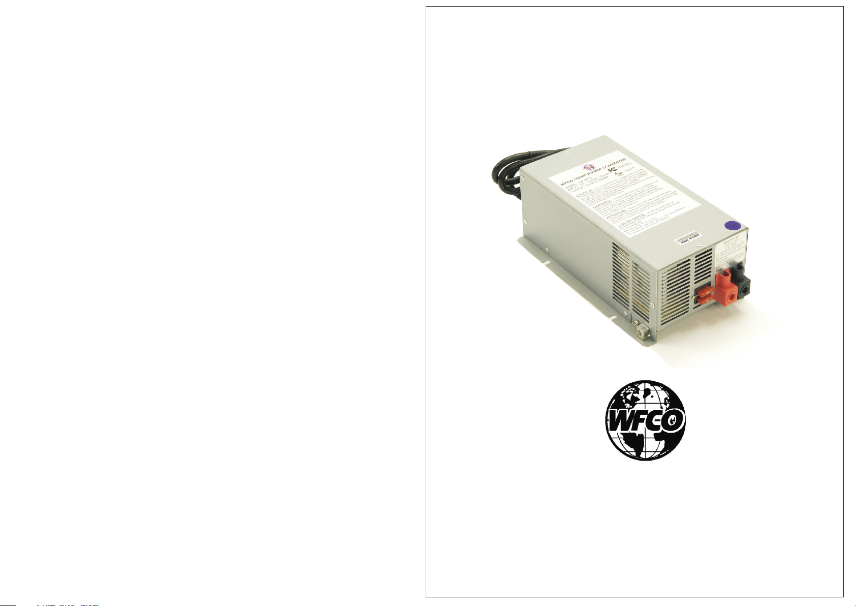
Operator Manual
For use with WFCO ULTRA III Deckmount Converter
WF-9800 Series
(model number located on the cover of the unit)
TM
Distributed in the U.S.A. and Canada by
ARTERRA DISTRIBUTION
Sales (574) 294-8997
Warranty Service (877) 294-8997
Fax (574) 294-8698
www.wfcoelectronics.com
Page 2
Installation and Servicing of the WFCO WF-9800 Series Power Center
!
CAUTION
!
This product should be installed by an experienced technician.
CAUTION and care must be taken when servicing this equipment.
To prevent severe shock or electrocution consult your servicing dealer.
No serviceable parts.
!
WARNING
!
This unit employs components that tend to produce arcs or sparks.
To prevent fire or explosion, do not install in compartments
containing batteries or flammable materials
!
CAUTION
!
(LP gas).
To prevent fire, do not cover or obstruct ventilation openings.
Do not mount in zero-clearance compartment.
Overheating may result.
For continued protection against risk of fire, or electric shock
replace only with same type and ratings of fuse.
!
CAUTION
!
Check on a monthly basis the fluid level in any battery connected to RV
charging system.
TM
General Consumer Information
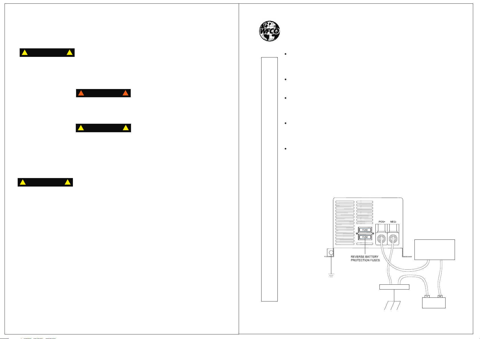
Reverse Battery Protection
This feature prevents permanent damage to the converter from an incorrect
battery connection.
Automatic Cooling Fan
The fan is variable speed and current controlled.
Electronic Current Limiting
Automatically shuts down power during overload or short-circuit conditions.
Automatically returns to normal operation after conditions are corrected.
DC Fuses
Reverse battery protection fuses; replace with
ATC “Littelfuse ” Type 257 fuse.
®
Lightweight
- 35 A unit weighs only 9.03 lbs.
- 45 A unit weighs only 11.20 lbs.
- 55 A unit weighs only 11.57 lbs.
- 65 A unit weighs only 14.33 lbs.
- 75 A unit weighs only 14.88 lbs.
This product is not ignition protected and should not be installed in an
®
LP compartment.
3
INSTAL L ATION INSTRUCTIONS
Distribution Panel/
Power Center
WF-8930/50NP
CHASSIS
(EARTH)
GROUND
GROUND BAR
12 V
BATTERY
Page 3
Converter Operation Modes
TM
TM
Troubleshooting WF-9800 Series Converter
All WFCO power converters are automatic three-stage switching
power supplies. The converter senses which mode it needs to be in by
checking the RV system voltage.
The three modes/stages of operation include:
Absorption mode/Normal operation
Nominal battery charge and supplies power to appliances
Bulk mode/Charge mode
Fast battery charge and supplies power to appliances
Float mode/Trickle charge
Trickle battery charge during storage
Absorption Mode: During this mode, the converter output is in the
13.6 Vdc range. This is the normal operation mode. This mode
provides the 12 Vdc and current required by the 12 Vdc RV appliances,
as well as slow charging the battery.
Bulk Mode: In this mode, the output voltage of the converter will
switch to 14.4 Vdc for a maximum of four hours. If the converter
cycles between “Absorption and Bulk mode,” there could be a shorted
battery cell or other issues.
Float Mode: In this mode, the converter is charging the battery with
a trickle voltage of 13.2 Vdc. When the converter senses a demand
(by turning on lights), the converter automatically returns to the
“Absorption mode”.
OPERATI O N A L FEATURES
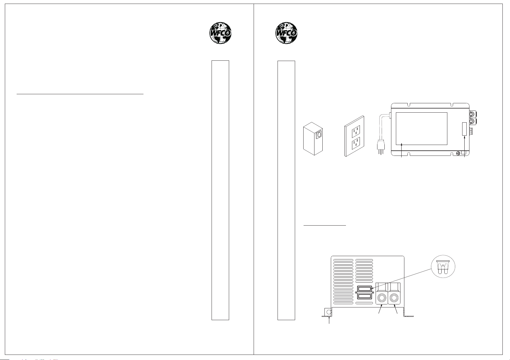
If the input from shore power is 105 Vac-130 Vac to the receptacle,
check the reverse battery protection fuse on the front plate of the
WF-9800 deckmount converter. Visually inspect the fuses for any
breaks/opens. If the fuses do not appear to be open, use a tester to
check for continuity.
DC
OUTPUT
-98XX
SHORE POWER
AC OUTPUT
(30 A OR 50 A)
RECEPTACLE
AC OUTPUT
(Power Center)
AC INPUT
F
W
:
EL
D
MO
MODEL LABEL
SERIAL LABEL
Reverse
Battery
Protection
Fuses
If the reverse polarity fuses are blown, it means the RV battery was
accidentally connected in reverse, either at the battery or at the
converter. Reconnect properly, then replace the fuse with the same
type and amp rating as the original “Littelfuse ” Type 257 automotive-
®
style fuse.
IMPORTANT: These fuses protect the converter from damage in the
event that the RV battery is accidentally connected in reverse. A reverse
battery connection, even for a second, is the only reason that these fuses
will blow
.
6
7
TROUBLESHOOTING INSTRUCTIONS
Ground
FUSE
FUSE
RED
POS
+
NEG
BLACK
-
“Littelfuse ” Type 257 fuse
ATC Style
®
Page 4
TM
TM
WF-9800 Series Troubleshooting
Before
ch
ec
king t
h
e c
on
ve
r
te
r
ou
d
isco
n
ne
c
t
the b
a
tt
e
ry c
ab
le
s
at
the
plu
g
g
e
d i
n
to A
C
so
ur
c
e
(
105
-
132
v
olt
a
g
e a
t the
ba
tte
r
y
with a
vo
lt
m
d
is
co
n
nec
ted
b
att
e
ry c
ab
les;
p
la
c
the
+ p
o
s
itive
re
d b
a
tter
y w
ire
a
nd p
p
robe
on
t
h
e
-N
e
gat
iv
e
blac
k
wire
ha
ve g
oo
d
co
n
ne
cti
o
n
s a
t
the
c
ab
w
ith
no
l
oa
d, th
e
co
n
verte
r
is
f
unc
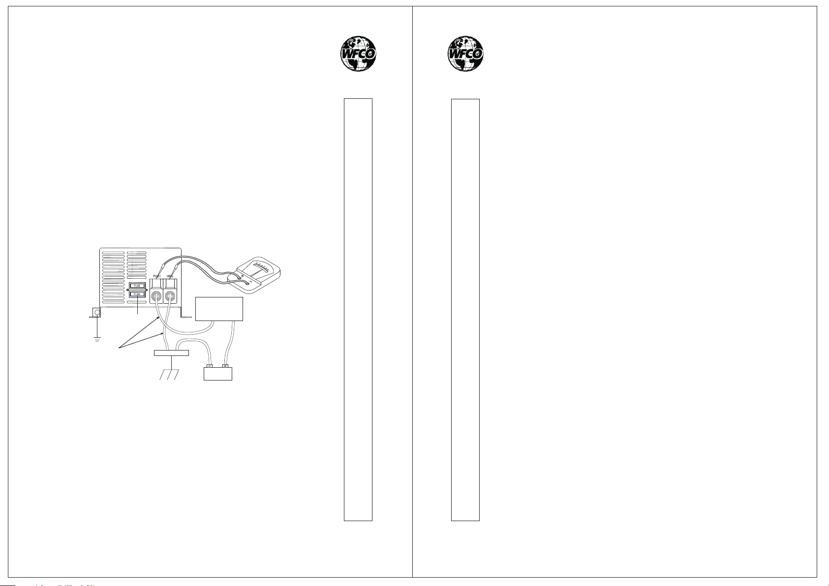
Nominal setup for WF-9800 Series
REVERSE BATTERY
CHASSIS
(EARTH)
GROUND
PROTECTION FUSES
FOR TESTING PURPOSES
DISCONNECT
THESE OUTPUT WIRES
GROUND BAR
tp
u
ba
V
olts). C
ete
e th
o
le
s.
tionin
t
vo
tter
r
. P
e
P
la
ce
n
th
I
f th
lt
a
g
e
, it is n
y
. M
a
h
ec
k the
la
c
e t
he
osit
iv
e
(re
th
e
N
e
e
b
a
ttery cab
e v
olt
g p
r
ope
Distribution Panel/
Power Center
WF-8930/50NP
12 V
BATTERY
k
e
sure th
pr
ga
tiv
a
g
e
rly.
d)
re
co
o
e
be
m
c
e
le
a
e
ss
e
n
v
er
s o
e
te
(b
la
.
B
ds 13
0V
a
ry t
c
o
ter ou
n
th
r pr
c
k)
e
s
.6
D
C
2
0
V
u
nv
e
o
V
o
m
r
b
e
e
r
te
tp
e o
e
ter
you
dc (+
GENERAL COMPLIANCE INFORMATION
r i
s
u
t
n
TROUBLESHOOTING INSTRUCTIONS
/-
.2
)
The WF-9800 Series units are UL-Listed, and cUL-Listed (Canadian).
They comply with FCC Class B requirement (see below)
FCC Compliance Class B
NOTE: This equipment has been tested and found to comply with the limits
for a Class B digital device, pursuant to Part 15 of the FCC Rules. These
limits are designed to provide reasonable protection against harmful
interference when the equipment is operated in a commercial environment.
This equipment generates, uses, and can radiate radio frequency energy and,
if not installed and used in accordance with the instruction manual, may
cause harmful interference to radio communications. Operation of this
COMPLIANCE
equipment in a residential area is likely to cause harmful interference in
which case the user will be required to correct the interference at his own
expense.
®
®
I
f
the
or
th
-
a
n
- an o
-
l
oo
-
im
I
f the
re
a
ds
C
on
co
e
op
se
pr
c
ze
ta
n
batte
e
n
pe
n w
g
ro
o
p
e
o
n
ro v
c
t C
v
e
r
te
ry is
inline
ir
e
u
n
d c
r t
or
v
e
r
te
olts
h
eng
b
qu
r o
r
f
U
n
f
u
e
o
e
use
,
the c
u
tpu
o
t
se
twe
n
n
s
SA
e
c
in
s a
,
ha
e
c
t
n
ti
on
I
n
nc
v
rg
th
t
on
olta
ing, c
e
h
e
d
AC
v
e
. Te
ba
co
rte
g
e
vo
r
ch S
a
h
tt
e
n
verte
is
t
ry
ec
lt
n
the
a
up
k fo
wir
r a
g
e are
o
t
p
b
a
tte
r
y
re
a
ds
in t
he
0.0
Vdc
ra
nge,
r
:
e
(
if ins
talle
d b
y O
E
M
)
n
d
the
R
V
b
a
tter
y
9
f
or
un
go
od
,
b
ut
the
c
o
n
ve
r
ter
o
utp
u
t sti
ll
c
ti
oning
p
rope
r
ly.
t
at
1
(87
7
)
2
94-
8997.
8
Page 5
Consumer Limited Warranty
WFCO Electronic Products
TM
For
WFCO extends to the original owner a Two-Year Limited Product Warranty.
This Warranty is in effect from the date of original purchase for a period of two
(2) years. This Limited Warranty is extended specifically for and is limited to
recreational vehicle application and is valid only within the continental United
States, Alaska, Hawaii and the provinces of Canada. WFCO warrants to the
owner that its products are free from defects in material and workmanship
under normal use and service, based on its intended use and function. This
Warranty is limited to the repair or replacement, at WFCO' s discretion, of any
defective parts or defective assembly. Any implied warranties of merchantability
or fitness for intended use are limited in duration unless applicable State Law
provides otherwise. You may have other rights as specified by each individual
state.
EXCLUSIONS and LIMITATIONS
The OEM Warranty specifically does not apply to the following:
Any WFCO product that has been repaired or altered by any unauthorized
person. Any damage caused by misuse, faulty installation, testing, negligence
or accident or any WFCO product installed in a commercial vehicle.
Any WFCO product whose serial number has been defaced, altered or removed.
Any WFCO product whose installation has not been in accordance with the
WFCO written instruction. Any consequential damages arising from the loss of
use of the product including, but not limited to, inconvenience, loss of service,
loss of revenue, loss or damage to personal property and cost of all services
performed in removing or replacing the WFCO product. Specifications are
subject to change without notice or obligation.
TM
LIMITED WARRANTY
CONSUMER WARRANTY CLAIM PROCEDURE
Upon determination and validation by an authorized OEM dealer that a WFCO
product has a defect, the dealer shall contact the WFCO warranty service
number (877) 294-8997 and obtain a return goods authorization (RGA) number.
This number shall appear on all correspondence with warranty service. Upon
validation of the warranty, WFCO shall replace or repair the product with a like
product. The RGA number shall be placed on the outside of the carton used to
return the product, for ease of identification. Do not mark directly on the
product. The product must be packaged properly to avoid further damage to
the product, which could cause a non-warrantable condition.
CD- M-000 03-7
10
Page 6
TM
OEM Installation Manual
For use with WFCO ULTRA III Deckmount Converter
WF-9800 Series Specifications
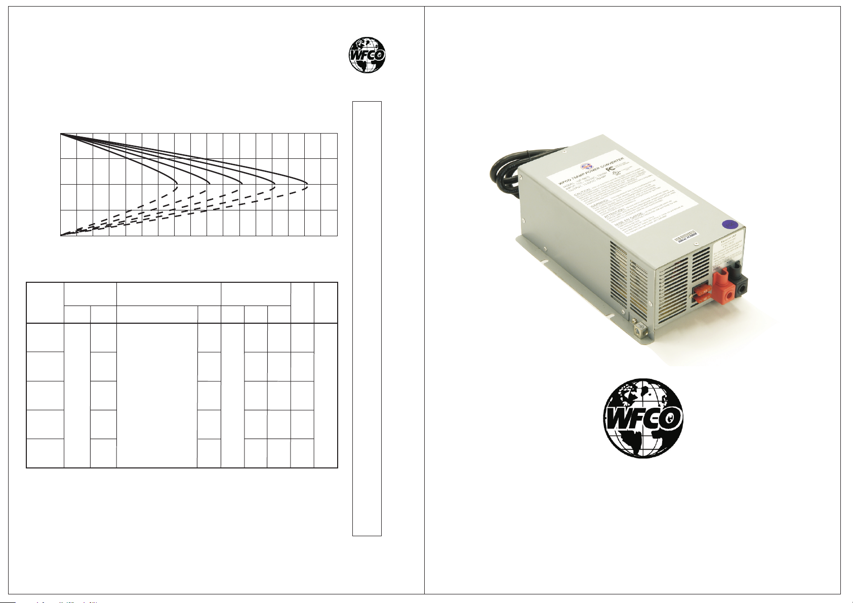
Output Load Curve
Model: WF-9835, 9845, 9855, 9865 and 9875
13.6 Vdc
13.2 Vdc
0.0 Vdc
Over the amperage rating load
will cause the output
to fold back.
5 10 15 20 25 30 35 40 45 50 55 60 65 70 75 80 85
WF-9800 Facts Summary
Model
No.
WF - 9835
WF - 9845
WF - 9855
WF - 9865
WF - 9875
AC Input
Voltage
(V)
105
to
120
Vac
60 Hz
Current
(A)
7.4
9.5
11.5
13.9
15.7
DC Output Ranges
Volts (V)
Bulk Charge Mode:
14.4 Vdc, 4hr max.
Absorption Mode:
13.6 Vdc
Float Mode:
13.2 Vdc
WF-9800 Series
(model number located on the cover of the unit)
SPECIFICATI O N S
(in)
7.48
8.66
8.66
5
987
Weight
(lbs)
4.0
5.25
5.5
6.25
6.75
Fan
Cooled
TM
Yes
986
Width
(in)
5.70
5.94
5.94
6.30
6.30
5
Length
10.27
10.27
84
9
5
Amps
(A)
35
45
55
65
75
5
3
98
5
985
Dimensions
Height
(in)
3.94
CD- M-000 03-7
4
Distributed in the U.S.A. and Canada by
ARTERRA DISTRIBUTION
Sales (574) 294-8997
Warranty Service (877) 294-8997
Fax (574) 294-8698
www.wfcoelectronics.com
Page 7
OEM Installation of the WFCO WF-9800 Series Power Center
Select a mounting location near the shore power and battery (batteries).
ount in an area where the owner is unlikely to store items, as this
M
could reduce clearance requirements, obstruct ventilation openings
and effect the performance of the converter.
Select a mounting location that is appropriate to prevent excessive
heat, water, moisture, dust and dirt entering the unit installed. As a rule
allow two cubic feet of clear airspace and or any additional venting as
necessary to prevent the unit from overheating. All installation should
be tested for overall performance.
!
WARNING
This unit employs components that tend to produce arcs or sparks.
To prevent fire or explosion, do not install in compartments
containing batteries or flammable materials
!
CAUTION
To prevent fire, do not cover or obstruct ventilation openings.
Do not mount in zero-clearance compartment.
Overheating may result.
For continued protection against risk of fire, or electric shock
replace only with same type and ratings of fuse.
During the manufacturing process, be sure that all converter openings
are protected from debris falling into the unit as this could cause the
components to short out. (This is a non-warranty item.)
NOTE: If the reverse battery protection fuses are blown during
installation, be sure that the battery has been connected properly, then
replace the fuses with ATC “Littelfuse ” Type 257 with the same
rating as the original.
This product is not ignition protected and should not be installed in an
LP compartment.
For proper wire sizes and torque requirements, refer to the label on the
back of the unit.
!
(LP gas).
!
®
TM
TM
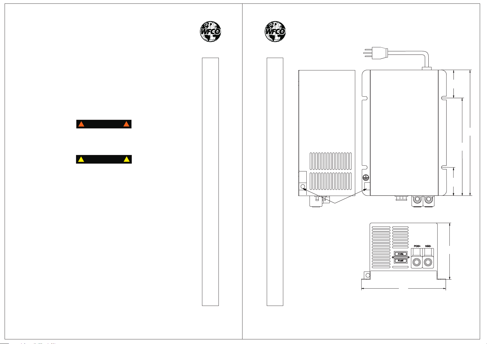
WF-9800 Series Converter Dimensions
INSTAL L ATION INSTRUCTIONS
2
Dimensions
A: 7.50? (WF-9835)
8.76? (WF-9845, 9855)
10.26? (WF-9865, 9875)
B: 5.53? (WF-9835)
6.79? (WF-9845, 9855)
7.52? (WF-9865, 9875)
C: 1.97? (WF-9835/45/55)
2.74? (WF-9865/75)
D: 5.70? (WF-9835)
5.94? (WF-9845, 9855)
6.30? (WF-9865, 9875)
E: 3.94? (WF-9800 Series)
CHASSIS
GROUND
REVERSE POLARITY
INSTAL L ATION INSTRUCTIONS
FUSES USED:
WF-9835 - 35 Adc
WF-9845 - 30/30 Adc
WF-9855 - 35/35 Adc
WF-9865 - 40/40 Adc
WF-9875 - 40/40 Adc
3
D
C
A
B
C
C
E
 Loading...