

Page 1
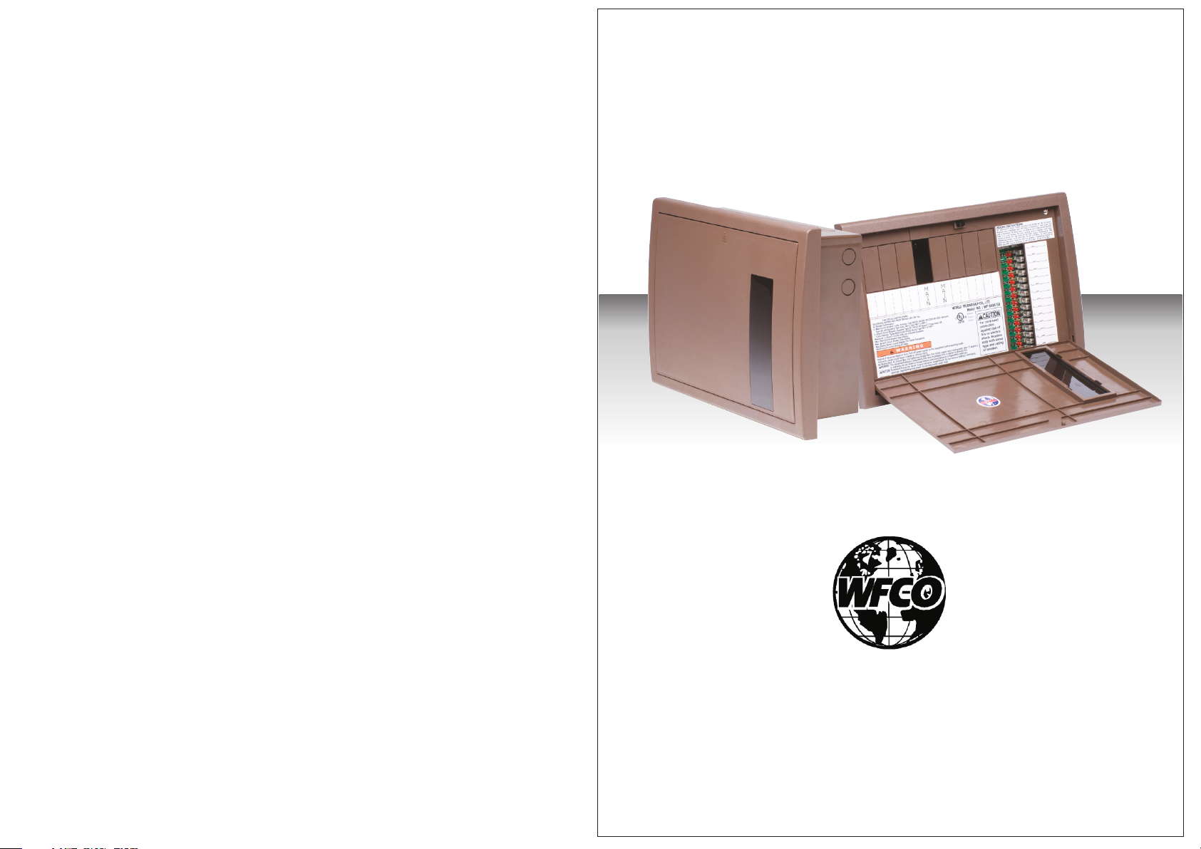
Operator Manual
For use with WFCO ULTRA III Distribution Center
Model WF-8930/50
TM
Distributed in the U.S.A. and Canada by
ARTERRA DISTRIBUTION
Sales (574) 294-8997
Warranty Service (877) 294-8997
Fax (574) 294-8698
www.wfcoelectronics.com
Page 2
Installation and Servicing of the WFCO WF-8930/50 Series Power Center
!
CAUTION
!
This product should be installed by an experienced technician.
CAUTION and care must be taken when servicing this equipment.
To prevent severe shock or electrocution consult your servicing dealer.
No serviceable parts.
!
WARNING
!
This unit employs components that tend to produce arcs or sparks.
To prevent fire or explosion, do not install in compartments
containing batteries or flammable materials
!
CAUTION
!
(LP gas).
To prevent fire, do not cover or obstruct ventilation openings.
Do not mount in zero-clearance compartment.
Overheating may result.
For continued protection against risk of fire, or electric shock
replace only with same type and ratings of fuse.
!
CAUTION
!
Check on a monthly basis the fluid level in any battery connected to RV
charging system.
TM
General Consumer Information
®
UL-Listed Main Circuit Breakers, rated for 30/50 Amp 120V/240 Vac
Acceptable circuit breakers are as follows:
Manufacturer
Cutler Hammer
ITE/Siemens
Square D
®
UL Listed Branch Circuit Breakers, rated for 120/240 Vac, maximum 20 Aac
Acceptable circuit breakers are as follows:
Manufacturer
Cutler Hammer
ITE/Siemens
Square D
A replacement or additional circuit breaker shall be of the same manufacturer,
type designation, and equal or greater interrupting rating, not to exceed 50 A.
- “Short-Circuit-Current” rating for the breaker should be 10,000 A
Breaker Filler Plates:
Manufacturer
WFCO
Model/Cat. No./Type
Type BR230, BR250, or C230, or C250
Type QP
Type HOM
Model/Cat. No./Type
Type Bd2020, A2020
Type QP or QT
Type HOMT
at 120/240 Volt AC.
Model/Cat. No./Type
FP-01 (brown) or FP-01B (black)
This product is not ignition protected and should not be installed in an
®
LP compartment.
INSTAL L ATION INSTRUCTIONS
2
Page 3
Top view
13,7"
TM
TM
INSTAL L ATION INSTRUCTIONS
4,2"
TO BATTERY
FROM CONV ERTER+
TO BATTERY +
12,2"
Rear view
FROM CONV ERTER
NEGATI VE B ATTE RY TE RMINAL
FUSE PAN EL TO GROU ND J UMPER
3/4"
1,9"
20A
NEGATI VE TERM IN AL JU MP ER
2"
20A 120VAC RECEPTACLE
4,2"
3/4"
Bottom view
13,7"
"
3/8"
1"
7/8"
RECEPTAC LE
9,3"
8,3"
50A
or
50A
HOLD DOWN
MAIN BREA KE R
30A
WIRE
GREEN
AC GROUND
TERMINA L BAR
INSTAL L ATION INSTRUCTIONS
AC NEUTRA L
TERMINA L BAR
(NOT GR OU NDED)
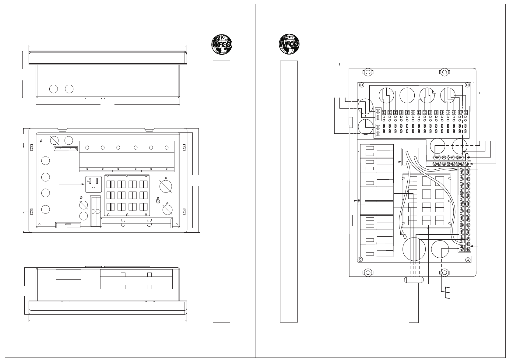
The wiring diagram of 8930/50
3
4
BLACK
WIRE
STRAIN
REIEFS
50 AMP
POWER COR D
WHITE
WIRE
CHASSIS
Page 4
TM
Consumer Limited Warranty
for
WFCO Electronic Products
WFCO extends to the original owner a Two-Year Limited Product Warranty.
This Warranty is in effect from the date of original purchase for a period of two
(2) years. This Limited Warranty is extended specifically for and is limited to
recreational vehicle application and is valid only within the continental United
States, Alaska, Hawaii and the provinces of Canada. WFCO warrants to the
owner that its products are free from defects in material and workmanship
under normal use and service, based on its intended use and function. This
Warranty is limited to the repair or replacement, at WFCO' s discretion, of any
defective parts or defective assembly. Any implied warranties of merchantability
or fitness for intended use are limited in duration unless applicable State Law
provides otherwise. You may have other rights as specified by each individual
state.
EXCLUSIONS and LIMITATIONS
The OEM Warranty specifically does not apply to the following:
Any WFCO product that has been repaired or altered by any unauthorized
person. Any damage caused by misuse, faulty installation, testing, negligence
or accident or any WFCO product installed in a commercial vehicle.
Any WFCO product whose serial number has been defaced, altered or removed.
Any WFCO product whose installation has not been in accordance with the
WFCO written instruction. Any consequential damages arising from the loss of
use of the product including, but not limited to, inconvenience, loss of service,
loss of revenue, loss or damage to personal property and cost of all services
performed in removing or replacing the WFCO product. Specifications are
subject to change without notice or obligation.
TM
LIMITED WARRANTY
CONSUMER WARRANTY CLAIM PROCEDURE
Upon determination and validation by an authorized OEM dealer that a WFCO
product has a defect, the dealer shall contact the WFCO warranty service
number (877) 294-8997 and obtain a return goods authorization (RGA) number.
This number shall appear on all correspondence with warranty service. Upon
validation of the warranty, WFCO shall replace or repair the product with a like
product. The RGA number shall be placed on the outside of the carton used to
return the product, for ease of identification. Do not mark directly on the
product. The product must be packaged properly to avoid further damage to
the product, which could cause a non-warrantable condition.
CD- M-000 04-6
5
Page 5
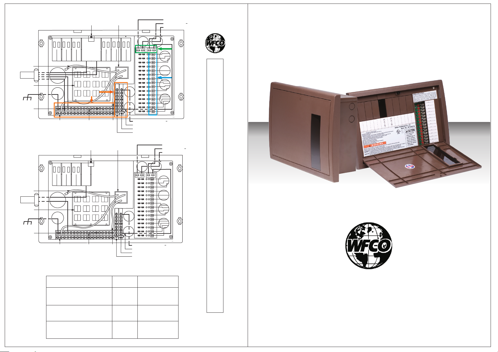
BLA CK
WIR E
50 AMP
STR AIN
REL IEFS
CHA SSIS
WHI TE
WIR E
MAI N BREAK ER
HOL D DOWN
50A
A
20A
REC EPTACL E
TO BAT TERY +
TO BAT TERY
FRO M CONVE RTER+
B
C
TM
OEM Installation Manual
For use with WFCO ULTRA III Distribution Center
Model WF-8930/50
INSTAL L ATION INSTRUCTIONS
BLA CK
WIR E
50 AMP
STR AIN
REL IEFS
CHA SSIS
WHI TE
WIR E
A
B
C
AC NE UTRAL
TER MINAL B AR
(NO T GROUN DED )
AC NE UTRAL
TER MINAL B AR
(NO T GROUN DED )
AC GR OUND
TER MINAL B AR
MAI N BREAK ER
HOL D DOWN
30A
AC GR OUND
TER MINAL B AR
Torque specifications
TERMINAL DESCRIPTION
TERMINAL BARS:
GROUND AND NEUTRAL
DC FUSE PANEL LUGS:
+VCC, NEG-, POS+
DC FUSE PANEL:
SINGLE CIRCUIT TERMINALS
GRE EN
WIR E
20A
REC EPTACL E
GRE EN
WIR E
TORQUE
(in. - lbs.)
FRO M CONVE RTER
FUS E PAN EL TO GROU ND JU MPE R
NEG ATIVE TE RMIN AL JUMP ER
NEG ATIVE BAT TERY TE RMINA L
TO BAT TERY +
TO BAT TERY
FRO M CONVE RTER+
FRO M CONVE RTER
FUS E PANEL TO GR OUND J UMPER
NEG ATIVE TE RMIN AL JUMP ER
NEG ATIVE BAT TERY TE RMINA L
WIRE GAUGES
(AWG)
25
30
35
25
32
45
20
25
30
10-14 AWG Wire
8 AWG Wire
6 AWG Wire
10 AWG Wire
8 AWG Wire
4-6 AWG Wire
14 AWG Wire
12 AWG Wire
10 AWG Wire
CD- M-000 04-6
4
TM
Distributed in the U.S.A. and Canada by
ARTERRA DISTRIBUTION
Sales (574) 294-8997
Warranty Service (877) 294-8997
Fax (574) 294-8698
www.wfcoelectronics.com
Page 6
OEM Installation of the WFCO WF-8930/50 Series Power Center
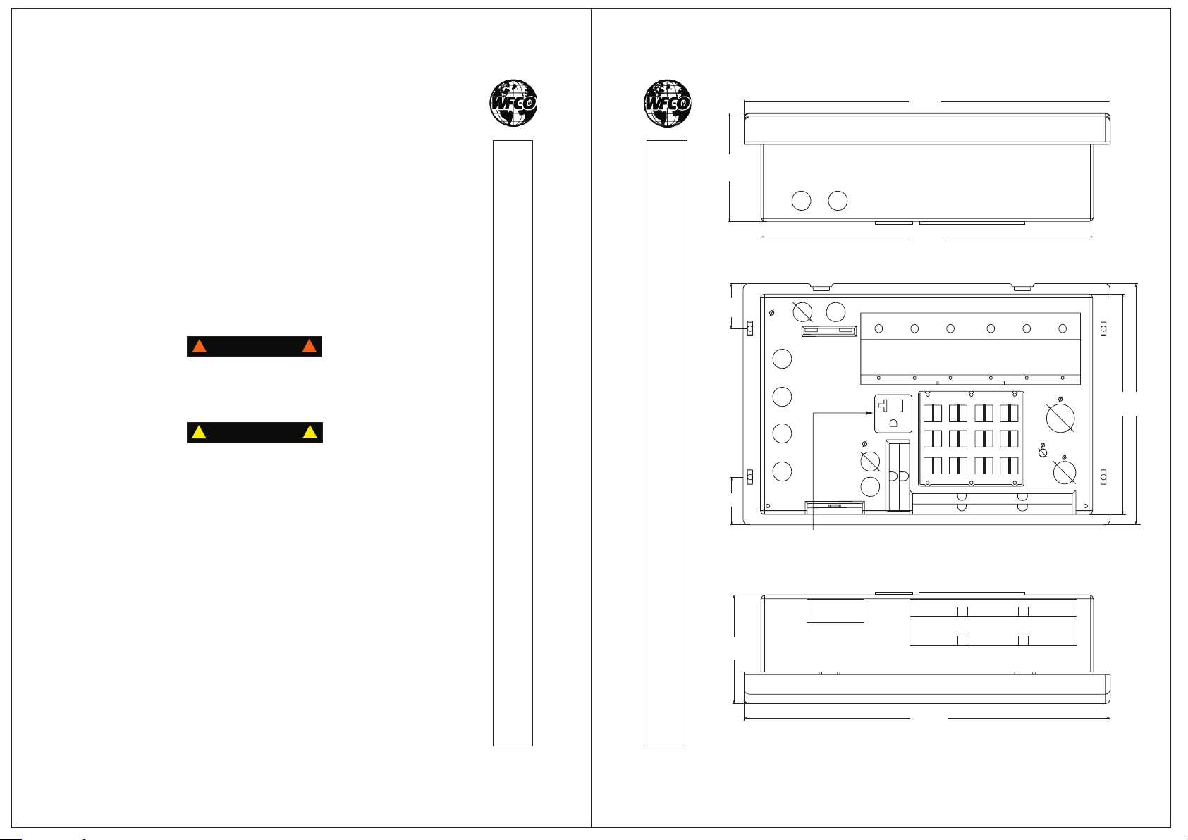
Select a mounting location near the shore power and battery (batteries)
and cut a rough opening 1/8? wider than the box to allow the power
center to slide in easily.
Two sizes of knockouts have been provided: a 1" knockout for the 50 amp
and a 3/4" knockout for the 30 amp power cord. The 7/8" holes are provided
for the 12 Vdc installations. There is also a series of built-in 120 Vac strain
reliefs for Romex and should be used only with 10-2 through 14-2 gage
wires, one wire per strain relief opening.
Select a mounting location that is appropriate to prevent excessive
heat, water, moisture, dust and dirt entering the unit installed. All
installation should be tested for overall performance.
TM
TM
Top view
13,7"
INSTAL L ATION INSTRUCTIONS
4,2"
12,2"
Rear view
3/4"
1,9"
!
WARNING
!
This unit employs components that tend to produce arcs or sparks.
To prevent fire or explosion, do not install in compartments
containing batteries or flammable materials
!
CAUTION
!
(LP gas).
To prevent fire, do not cover or obstruct ventilation openings.
For continued protection against risk of fire, or electric shock
replace only with same type and ratings of fuse.
During the manufacturing process, be sure that all converter openings
are protected from debris falling into the unit as this could cause the
components to short out. (This is a non-warranty item.)
C Fuses
D
- Fifteen 12 Vdc circuits (including two circuit for slideouts)
- Maximum of 30 Adc fuse for DC circuits 1 and 2 (all others max. 20 Adc)
If the fuses are blown during installation, replace the fuses with
ATC “Littelfuse ” Type 257 with the same rating as the original.
®
This product is not ignition protected and should not be installed in an
LP compartment. For proper wire sizes and torque requirements, refer
to the label on the back mbly.
of the door asse
2
3
INSTAL L ATION INSTRUCTIONS
2"
20A 120VAC RECEPTACLE
3/4"
1"
3/8"
7/8"
"
8,3"
Bottom view
4,2"
13,7"
Remember to select the proper gauge wire for the load, according to
the National Electric Code (NEC). Be sure to use appropriate Romex
connector and strain reliefs to secure the wires to the distribution panel.
9,3"
 Loading...