


TRAY DISHWASHER
WD-215T
(Translation of original documentation)
Read the manual before using the machine!
Installation and user manual
S/N: (En) Valid from: 201812 Rev.: 6.0

WD-215T Rev. 6.0 (201812)
1. General instructions ........................................................................ 1
1.1 Symbols used .................................................................................................. 2
1.2 Machine rating ................................................................................................. 3
1.3 Checking that the machine and manual correspond ........................................ 3
1.4 EU Declaration of Conformity .......................................................................... 4
2. Safety instructions ........................................................................... 5
2.1 General information ......................................................................................... 5
2.2 Transport .......................................................................................................... 6
2.3 Installation ........................................................................................................ 6
2.4 Detergent and drying agent ............................................................................. 6
2.5 Operation ......................................................................................................... 6
2.5.1 High temperatures .................................................................................... 6
2.5.2 Risk of crushing ........................................................................................ 6
2.5.3 Risk of slipping .......................................................................................... 7
2.5.4 Sounds ...................................................................................................... 7
2.6 Cleaning the machine ...................................................................................... 7
3. Installation instructions ................................................................... 8
3.1 General information ......................................................................................... 8
2 Requirements for the installation site ............................................................... 8
3.
3.2.1 Lighting ..................................................................................................... 8
3.2.2 Ventilation ................................................................................................. 8
3.2.3 Power supply ............................................................................................ 8
3.2.4 Water ........................................................................................................ 9
3.2.5 Drain/waste pipe ....................................................................................... 9
3.2.6 Space for servicing ................................................................................... 9
3.3 Transport and storage .................................................................................... 10
3.3.1 Unpacking ............................................................................................... 10
3.3.2 Recycling ................................................................................................ 10
3.4 Installation ...................................................................................................... 11
3.4.1 Preparing for the installation ................................................................... 11
3.4.2 Positioning the machine .......................................................................... 11

WD-215T Rev. 6.0 (201812)
3.5 Connections ................................................................................................... 12
3.5.1 Power supply .......................................................................................... 13
3.5.2 Water ...................................................................................................... 13
3.5.3 Ventilation ............................................................................................... 13
3.5.4 Steam (option, steam-heated machines) ................................................ 14
3.5.5 Condensation water (option, steam-heated machines) .......................... 14
3.5.6 Drain/waste pipe ..................................................................................... 14
3.5.7 Detergent and drying agent .................................................................... 14
3.6 Trial operation ................................................................................................ 17
3.6.1 Start-up schedule .................................................................................... 17
3.7 Documentation ............................................................................................... 18
4. Instructions for use ........................................................................ 19
4.1 Before washing .............................................................................................. 20
1.1 Machine design ....................................................................................... 20
4.
4.1.2 Preparations before filling ....................................................................... 21
4.1.3 Filling and heating ................................................................................... 23
4.1.4 Filing and heating the machine using TimerStart (optional) ................... 23
4.2 Using the machine ......................................................................................... 35
4.2.1 Washing .................................................................................................. 35
4.2.2 Checking the wash result ........................................................................ 35
4.2.3 Storage in the tray dispenser .................................................................. 36
4.2.4 Changing the water ................................................................................. 36
4.2.5 Emergency stop ...................................................................................... 36
4.2.6 Unloading trays manually ....................................................................... 36
4.3 After use ......................................................................................................... 37
4.3.1 Incorrect cleaning methods ..................................................................... 37
4.3.2 Daily cleaning ......................................................................................... 38
4.3.3 Cleaning and checking each week or as required .................................. 39
4.3.4 Cleaning in the event of an alarm or 1 time / year .................................. 41
4.3.5 Operating problems ................................................................................ 42
5. Technical information .................................................................... 46

General instructions
1. General instructions
Read the instructions in this manual carefully as they contain important information regarding the correct, effective and safe installation, use and servicing of the
machine. Service personnel should have access to all documentation for the
machine.
Keep this manual in a safe place so that it can and should be used by other operators of the machine.
• The machine is intended to be used for washing trays found in the general
catering and restaurant trade. Other uses are NOT recommended!
• The machine can be equipped with a number of different options. Certain
options may be standard in a number of countries. Check what your machine is equipped with.
• The machine’s display indicates what the machine is doing. The machine’s
various temperatures and any alarms are also shown.
• The capacity requirements of the machine can be found in the TECHNICAL
DATA chapter.
• The electronics in the machine are RoHS compatible.
WD-215T Rev. 6.0 (201812)
Before the machine is started up and used, the following points should be observed:
• The SAFETY INSTRUCTIONS chapter must be studied carefully before
commissioning the machine.
• Installation of the machine must be performed in accordance with the requirements and instructions indicated in the INSTALLATION INSTRUCTIONS and TECHNICAL SPECIFICATIONS chapters.
• Any personnel who may at some point use the machine must be trained in
its operation, use and care.
• The machine should not be used by anyone suffering from a physical or
mental illness.
• A close eye should be kept on any children in the vicinity of the machine to
ensure they do not tamper with it.
• All cover plates must be installed during use.
The machine and equipment requires an annual service. Contact one of our authorised and trained service companies for such a service.
1

General instructions
1.1 Symbols used
This symbol warns of situations where a safety risk may arise. The instructions
given should be followed in order to prevent injury and dangerous situations.
This symbol on a machine part warns of electrical equipment. The machine must
be entirely non-live during servicing, turn off the power at the power switch and if
required, the switch should be locked to prevent unintentional operation. The
component may only be removed by a qualified electrician.
This symbol warns that the machine’s electronics are sensitive to electrostatic discharge (ESD), which is why a static electricity wristband must be used when
handling the electronics at all times.
This symbol explains the right way to perform a task in order to prevent poor results and/or damage to the machine.
This symbol identifies recommendations and hints to help you get the best results
when washing, to increase the machine’s lifespan and reduce the risk of emergency shutdown.
WD-215T Rev. 6.0 (201812)
This symbol explains the importance of careful and regular cleaning of the machine to meet hygiene requirements.
This symbol warns of the importance to read the manual before using the machine.
This symbol warns that local regulations must be followed for recycling of packaging etc. as well as the destruction of the machine.
This symbol shows where any earth cable for potential equalisation can be connected. The earth bolt is placed on the machine’s stand.
2

General instructions
S/N:
V
Hz
A
kW
kW
kW
Type
Mårdvägen 4, S-352 45 VÄXJÖ SWEDEN
M
IP
1
2
5
9
6
4
8
11
3
7
10
!
marks_15
1.2 Machine rating
The machine has two rating plates, one of which is placed at the bottom of one
side of the machine and the other in the electrical cabinet. The technical information on the plates is also included on the machine's wiring diagram. The various
rating fields show:
WD-215T Rev. 6.0 (201812)
1. Machine type
2. Machine serial number
3. Year of manufacture
4. Enclosure protection class
5. Voltage
6. Number of phases with or without neutral
7. Frequency
8. Main fuse
9. Motor output
10. Electrical heating output
11. Max. output
1.3 Checking that the machine and manual correspond
Check that the type description on the rating plate corresponds with the type des-
ription on manual cover page. If manuals are missing, it is possible to order new
c
ones from the manufacturer or the local distributor. When ordering new manuals,
it is important to quote the machine number found on the rating plate.
3
WD-215T Rev. 6.0 (201812)
CE_16_2
1
2
3
5
6
7
7
7
8
6
6
6
4
General instructions
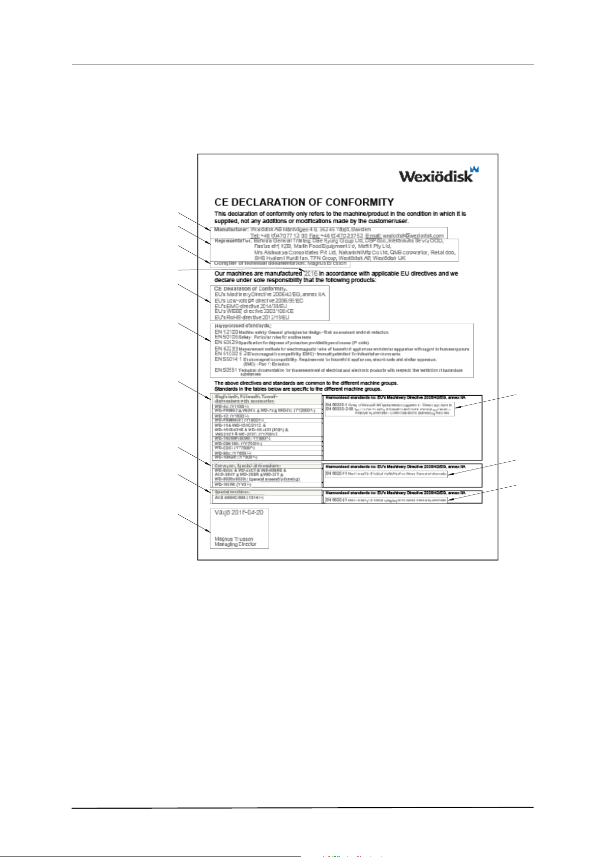
1.4 EU Declaration of Conformity
A so-called EU Declaration of Conformity is provided on delivery of the machine.
1. Contact details of the manufacturer (Wexiödisk AB, Mårdvägen 4, SE35245 Växjö, SWEDEN, Tel.: +46 470 771200, Fax: +46 470 23752,
E-mail: wexiodisk@wexiodisk.com).
2. Representatives of Wexiödisk AB.
3. Person responsible for the product’s documentation.
4. Year of manufacture of the product.
5. The EU Directives with applicable provisions to which all the machines,
special machines and accessories comply.
6. Harmonised standards for the Directives specified, and which the machines, special machines and accessories meet, wherever relevant.
7. Model designation and serial number of the machines, special machines
and accessories the document applies to.
8. Place and date with signature and name (in block letters) of the person responsible for ensuring compliance with legislation and regulations.
4

Safety instructions
2. Safety instructions
Read the chapter GENERAL INSTRUCTIONS carefully before starting work.
2.1 General information
The machine is CE marked, which means that it complies with the requirements
f the EU Machinery Directive with regard to product safety. Product safety
o
means that the design of the machine will prevent personal injury or damage to
property. The CE mark is only valid for an unmodified machine. Any damage to
the machine arising from failure to follow the instructions will invalidate the supplier’s warranty and product liability.
WD-215T Rev. 6.0 (201812)
Installation, repairs and servicing must be performed by an authorised engineer
in accordance with local and national rules in effect for such work with water and
drainage systems, electricity, ventilation and steam. We recommend that the
work is performed by the manufacturer or one of the manufacturer’s authorised
service companies.
To further improve safety during installation, operation and servicing, the operator
and the personnel responsible for installing and servicing the machine should
read the safety instructions carefully.
The machine’s electronics are sensitive to electrostatic discharge (ESD), which is
why a static electricity wristband must be used when handling the electronics at
all times.
Before the machine enters service, ensure that the personnel are given the necessary training in handling and looking after the machine.
In order to avoid dangerous situations, the following must be followed:
• Switch off the machine immediately in the event of failure or malfunction.
• Make sure the machine is non-live before removing the cover plate. Turn
off the power using the power switch. If required, the switch must be locked
to prevent unintentional operation.
• Shut off the tap for incoming water and drain the machine’s tank(s) before
starting work. Let the machine cool down as pipes for water, washing
pumps, booster heaters and valves become very hot when the machine is
in operation.
• The machine and equipment requires an annual service. The machine
should be serviced by a person authorised or trained to do so by us. Use
original spare parts.
• Warranty repairs must be performed by an authorised company. Contact
an authorised service company to draw up a programme of preventive care
5

Safety instructions
• The regular checks described in the manual must be carried out in accor-
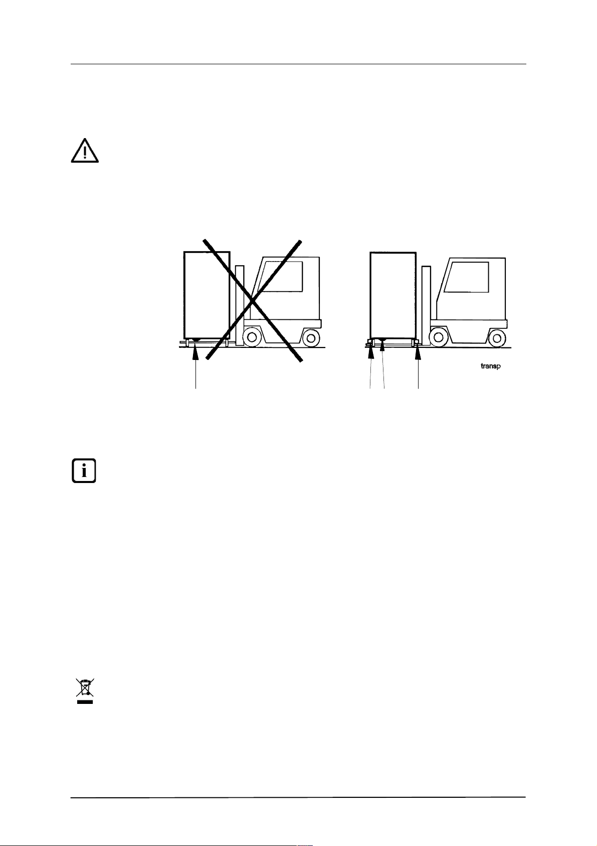
2.2 Transport
Handle the machine with care during unloading and transport; there is a risk of it
tipping over. Never lift or move the machine without using the wooden packaging
to support the stand.
2.3 Installation
• The machine is designed for quick electrical installation.
•
• Make sure that the mains voltage is the same as that indicated on the
WD-215T Rev. 6.0 (201812)
and maintenance. For authorised service companies, please see
www.wexiodisk.com or contact Wexiödisk AB.
dance with the instructions.
The machine must be connected to a lockable main switch.
machine’s rating plate.
For increased safety, it is recommended to equip the installation with a ground
fault circuit interrupter.
2.4 Detergent and drying agent
Be aware of the risks involved in handling detergents and drying agents. Protective gloves and safety glasses should be used when handling, and an eyebath
should be within easy access. Read the warning text on the detergent and drying
agent containers as well as the detergent supplier’s instructions.
2.5 Operation
Be very careful around the machine when it is in operation.
2.5.1 High temperatures
• The temperature of the washing and rinsing water is 60°C and 85°C. Do
ot open the machine until the rinsing phase has finished. The steam that
n
comes out of the machine after the wash has been completed is hot.
• Avoid touching hot pipes and booster heaters. The machine’s outer jacket
can also become hot during operation.
2.5.2 Risk of crushing
The machine, and any equipment, has moving parts before, during and after
washing. Be careful therefore to avoid crushing injuries. In connection with service or repairs that require the hood to be open, it must be secured by means of a
prop for example.
6

Safety instructions
2.5.3 Risk of slipping
The floor should be kept clean and dry to eliminate any risk of slipping. Mop up
any water and leftover food that has been spilt.
2.5.4 Sounds
The machine is not silent during operation, see TECHNICAL SPECIFICATIONS.
Hearing protection may therefore need to be used.
2.6 Cleaning the machine
The water in the tank has a temperature of approximately 60°C and contains de-
ergent. Be careful when draining and cleaning the wash tank. Wear protective
t
gloves and safety glasses and have an eyebath within easy access.
WD-215T Rev. 6.0 (201812)
7

WD-215T Rev. 6.0 (201812)
Installation instructions
3. Installation instructions
Read the chapters GENERAL INSTRUCTIONS and SAFETY INSTRUCTIONS
carefully before starting work.
3.1 General information
Read these instructions carefully, as they contain important information regarding
he correct installation method.
t
• The instructions should be used together with the machine’s wiring diagram and flow diagram for water and steam. These can be found in the
machine’s electrical cabinet.
• The machine can be equipped with a number of different options. Certain
options may be standard in a number of countries. Check what your machine is equipped with.
• If holes need to be drilled in the machine, the holes must be fitted with an
edge strip or similar protection.
3.2 Requirements for the installation site
3.2.1 Lighting
In order to ensure the best possible working conditions during installation, opera-
ion, servicing and maintenance, make sure that the machine is installed in a well-
t
lit room.
3.2.2 Ventilation
The machine produces heat and steam when in operation. In order to ensure the
best possible working conditions, a certain air renewal rate is required in the
dishwashing room. The ventilation requirements for the dishwashing room are to
be dimensioned on the basis of the applicable standards.
3.2.3 Power supply
Power supply connections are made by qualified personnel in a way that complies
with local and national regulations. The machine’s capacity requirements are stipulated in TECHNICAL SPECIFICATIONS.
8

Installation instructions
3.2.4 Water
Water connections are made by qualified personnel in a way that complies with
local and national regulations. The machine’s capacity requirements are stipulated in TECHNICAL SPECIFICATIONS.
3.2.5 Drain/waste pipe
There must be a waste pipe with an effective trap for the machine’s waste water
and for water used for rinse cleaning. The machine’s capacity requirements are
stipulated in TECHNICAL SPECIFICATIONS.
3.2.6 Space for servicing
A 1-metre area should be left clear in front of the machine for servicing purposes.
he area above the machine must not contain any equipment that may prevent
T
the fitting, servicing and replacement of parts. Depending on if the machine has
different accessories, there may also be such a requirement at the infeed and outfeed ends as well as above the machine.
WD-215T Rev. 6.0 (201812)
9
Installation instructions
A AB B
3.3 Transport and storage
Always transport the machine in an upright position.
Take care during transport, as there is a risk of tipping. NB: The machine must
not be transported without a pallet or other support. Some form of support beam
must always be used along the sides of the machine during transport. Otherwise
the machine may become damaged. When transporting the machine without a
normal wooden pallet, always check that none of the components underneath the
machine can be damaged.
WD-215T Rev. 6.0 (201812)
3.3.1 Unpacking
3.3.2 Recycling
A=Pumps
B=Spacers
If the machine is not being installed immediately, it must be stored in a frost-free
area where the air is dry.
Check that all parts have been delivered by comparing them with the delivery no-
e.
t
Remove the packing material. Inspect the machine for any transport damage.
Packaging must be sent for destruction or recycling in accordance with local regulations.
The machine is manufactured from stainless steel plate, among other things, and
also contains electronic components. Recycling of the appliance when its economic lifetime has been reached must be carried out in accordance with current rules and regulations.
10

Installation instructions
215T_plac
b
a
c
a a
3.4 Installation
3.4.1 Preparing for the installation
Check that there is sufficient room for the machine at the installation location.
• Check that correct connections are available for water, electricity, drainage
and possibly steam at the installation location. See TECHNICAL SPECIFICATIONS.
• Check that the overheating protection device is reset.
3.4.2 Positioning the machine
Check the following points before the machine is placed in position:
Check that the fuse for the machine at the site is off, blocked and that out-
•
going electrical circuits from the machine are non-live.
• Remove the protective plastic on the sides which are to be stood against a
wall.
• The distance between the wall and machine should be at least 15-30mm.
WD-215T Rev. 6.0 (201812)
Place the machine in position and check that it, and any accessories, are horizontally level. Adjust the height with the legs.
Check with a spirit level that the machine is standing level:
• On the cover edge of the front side (a) (tank body).
• On the cover of the infeed (b).
• On the cover of the outfeed (c).
. Once the machine has been filled with water, do another check to make sure the
machine is standing level.
11

Installation instructions
WD215T_12_R2
2
5
3
1
4
A
A
6,7
8
9 10
3.5 Connections
WD-215T Rev. 6.0 (201812)
Installation drawing
= Perforation in the end plate for drain connection
A
1. Electrical connection.
2. Cold water connection
3. Hot water connection
4. Reducing valve. The valve is used to adjust the final rinse flow.
5. Drain connection 50 mm.
6. Steam connection (steam-heated machines) (option)
7. Condensation water connection (option, steam-heated machines).
8. Alternative electrical connection from floor behind the front panel.
9. Alternative cold water connection from floor behind the machine.
10. Alternative hot water connection from floor behind the machine.
In the following chapter, figures are given in brackets to clarify what needs to be
done. These numbers refer to image and list above.
12

Installation instructions
3.5.1 Power supply
Information about electrical connections is available on the machine’s wiring diagram which is provided on delivery. Store the diagrams in the plastic pocket, located in the electrical cabinet, even after installation.
• The machine is designed for quick electrical installation.
• The machine has a built-in main switch. Connect the electric cable at (1).
• Check the direction of rotation of the pump motors during operation when
After completing the installation, switch on the main switch and all circuit breakers.
WD-215T Rev. 6.0 (201812)
In special cases, certain dishwashers may have an electrical connection
from the floor. The cable is then drawn behind the cover plate and through
the channelling at (8).
the tanks are full of water. The direction of rotation must conform without
exception to the direction of the arrow on the pump. Stop the dishwasher
immediately if the direction of rotation is incorrect and change two of the
incoming phases.
3.5.2 Water
3.5.3 Ventilation
• A shut-off cock must be installed on the incoming pipe.
It is important that the water supply has sufficient pressure to ensure the
•
correct flow of water to the machine. The required water flow and pressure
can be found in the TECHNICAL SPECIFICATIONS. If the water pressure
is too low, a booster pump must be fitted.
The water pipe is connected at (2, or alternatively 9) or at (3, or alternatively 10).
If the machine is connected with a hose, this should be steel braided and have an
internal diameter of at least 12 mm.
The hot water connection on the machine is fitted with a filter.
The cold water connection on the machine is fitted with a filter, non-return valve
and vacuum valve.
As the machine is fitted with a “Break Tank”, the connection is fitted with a filter.
The machine’s heat load for the room is stipulated in TECHNICAL SPECIFICA-
IONS.
T
The machine has a condensing battery connected to an exhaust fan to reduce the
amount of steam released. Extractor fans for extracting steam can be installed
above the infeed and outfeed openings, as well as above the area of the machine
where steam is emitted from the condensing fan.
If a hood is fitted over the machine, it much be positioned so that it covers the drying rack after the machine and preferably also the exhaust from the condensing
fan.
13

WD-215T Rev. 6.0 (201812)
Installation instructions
3.5.4 Steam (option, steam-heated machines)
Connect the pipe for steam inside the front cover plate (6). The connection is fitted
with a filter. A shut-off valve for steam must be installed on the incoming pipe. The
required steam pressure can be found in the TECHNICAL SPECIFICATIONS.
3.5.5 Condensation water (option, steam-heated machines)
Connect the pipe for condensation water inside the front cover plate (7). The pipe
is connected to the system’s steam boiler.
3.5.6 Drain/waste pipe
The waste water system connected to (5) should consist of a 50 mm metal pipe
hat will withstand mechanical impacts. Remove the perforated section of the end
t
plate at (A) and pull the pipe through the hole. The drain must run to a floor drain,
where its opening must be above the water level. Ensure that the drain connection
is kept in place by using e.g. cable ties in the designated areas.
The requirement for the floor drain capacity can be found in the TECHNICAL
SPECIFICATIONS.
3.5.7 Detergent and drying agent
Check what your machine is equipped with, which depends on the model, machine type and country.
• Use the same make and type of detergent and drying agent.
• With machines connected to cold water, the water pipe temperature may
be too low for use of powder or paste type detergents.
• If liquid detergent is used together with Wexiödisk’s detergent pump, the
detergent must be placed under the machine’s tank level.
• If equipment for a different type of detergent is used, it should preferably be
put on the wall behind the machine to avoid holes being drilled unnecessarily in the machine
The process of setting the detergent and drying agent dispenser is described in
the ADJUSTMENT INSTRUCTIONS.
For information about electrical connections, see the electrical diagram.
14
Installation instructions
WD215T_4_R1
6
1
9
8
7
5
4 3
2
Connection of the equipment
The machine is ready for fitting detergent and drying agent equipment, but this is
not included in the delivery. To avoid making unnecessary holes in the machine,
the equipment should be placed on the wall behind the machine.
WD-215T Rev. 6.0 (201812)
Connections for detergent and drying agent dosage.
1. Water outlet for detergent dosage on the incoming hot water pipe
2. Terminal box with connections for control of detergent and drying agent.
3. Plugged hole in the cover plate on the back of the machine for alternative
detergent connection. Drill a hole from the back of the chemical washing
tank through the plugged hole.
4. Plugged hole ø 22 mm for measuring cell on the front of the chemical wash
tank.
5. Plugged connection ø 11 mm for liquid detergent on the front of the chemical washing tank.
6. Plugged connection ø 18 mm for connecting hose for detergent in solid
form.
7. Connection for drying agent dosage by the booster heater.
8. Hole ø 25 mm for hose intended for detergent in solid form.
9. Hole ø 19 mm for drying agent hose.
15

Installation instructions
2
Plint_diskmedel
Electrical connection of the equipment
The machine comes ready for fitting detergent and drying agent equipment, but
this is not included with the machine.
To avoid making unnecessary holes in the machine, the equipment should be placed on the wall behind the machine on the outfeed side.
WD-215T Rev. 6.0 (201812)
Connections for detergent and drying agent.
16

Installation instructions
3.6 Trial operation
Prepare the machine for trial operation by following the INSTRUCTIONS FOR
USE. The instructions describe the measures that must be taken to prepare the
machine for operation.
3.6.1 Start-up schedule
This should be completed and signed by the customer on start-up.
Machine type:
Machine serial number:
Installation date:
Read the installation and user manuals carefully. Then check the following points:
1. Check:
WD-215T Rev. 6.0 (201812)
• Water, steam and drain connections
• That the machine is evenly balanced
• That the closed doors are in line
• The adaptation of any tray dispensers
• Detergent and drying agent
• That the filters, level pipe and curtains are in position
• The mini-switches for all the heating elements must be in the OFF position.
• That the overheating protection device is reset
2. Filling the machine:
• Switch on the main switch and press the 0/1 button
• Close the doors
• Fill the machine with water in accordance with the manual
Note: The booster heaters fill automatically when the doors are closed. The
machine has a filling check function for the booster heaters. When the function is activated, a check is carried out to ensure that the booster heaters
are full of water, before the element is switched on.
NB! If the filling is cancelled, the filling check will be restarted by the booster
heater from zero.
• When the filling check has been completed and all the tanks are full, the
mini-switches for the booster heaters switch on
3. Check the setting of the reference values
• All the reference values have been set to the recommended values on delivery
• Check that the motor cut-off switch for the infeed and outfeed conveyors
have been set correctly
17

Installation instructions
4. Start the machine:
• Check the direction of rotation of the pumps
• Check the function of the overload switch for the feed
5. Run a number of washes complete with loads and check:
• There are no water leaks
• The door breaker works
• Steam discharge from the machine
• The tank and final rinse temperatures are maintained
• The final rinse flow has been set correctly
• The washed items are clean
• The washed items are dried
6. Final check: Empty the machine and turn off the power using the main
switch.
WD-215T Rev. 6.0 (201812)
NB! If the direction of rotation is wrong, the phase must be inverted on the
incoming feed
(2.5 l/min. (factory setting))
• Re-tighten all the connections on the relays and circuit breakers
• Check that all the mini-switches and the motor cut-off switch are in the on
• Display the maintenance instructions supplied with the machine
7. Train the dishwashing personnel
• Washing
• Care (daily, weekly and other frequencies)
• Recommendation for annual service
3.7 Documentation
For correct use and servicing, it is essential that the documentation accompany-
ng the machine is made available to personnel who will be using the machine.
i
The installation and user manual, which describes handling and care among
other things, should be stored near the machine.
position.
18

Instructions for use
4. Instructions for use
Read the chapters GENERAL INSTRUCTIONS and SAFETY INSTRUCTIONS
carefully before starting work.
This chapter describes what must be done with the machine:
• Before washing
• How washing should be performed
• After completed washing
• In the event of error messages and troubleshooting
WD-215T Rev. 6.0 (201812)
The use of the machine is dependent on how the machine is equipped.
If the machine will not be used for a longer period, the power to the machine
should be turned off using the power switch, the water supply turned off and
machine should be left open.
19

Instructions for use
1
2
3
4
5
6
7
9
10
8
11
WD215T_ 11_R6
12
13
14
15
17
16
19
2021
22
23
18
26
24
25
21
27
28
11
4.1 Before washing
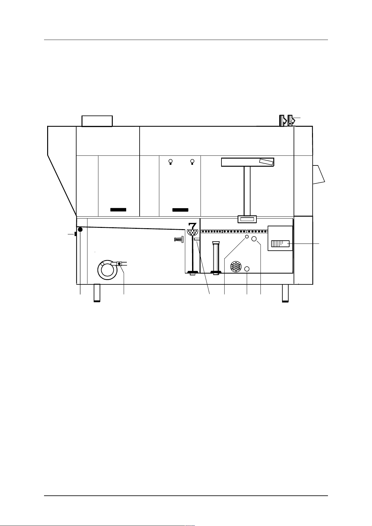
4.1.1 Machine design
WD-215T Rev. 6.0 (201812)
1. Display for messages.
. LED which indicates that functions are enabled.
2
3. Button for starting the filling process and heating of the machine.
4. Button for manually unloading the trays.
5. Button to start/stop the feed.
6. Button for diagnostics function (only for service engineers).
7. Button for diagnostic messages (only for service engineers).
8. LED for indication of alarms. If the LED flashes, the alarm can be reset by
pressing button (9).
9. Button for resetting alarm.
10. To/From
11. Emergency stop
20

Instructions for use
WD-215T Rev. 6.0 (201812)
12. Grille for drying zone fan
13. Door lock
14. Main switch
15. Wash nozzle
16. Wash arm
17. Curtain
18. Door
19. Tank filters
20. Pump filter
21. Rubber sleeve
22. Level pipe
23. Door
24. Outlet seal
25. Filter
26. Filter for the final rinse
27. Timer for a timed start of the machine (option)
28. Button for activating the timer (option)
In the following chapter, figures are given in brackets to clarify what is being referred to.
These numbers refer to image and list above.
4.1.2 Preparations before filling
Check:
That the machine and removable parts have been cleaned. If not – clean
•
them!
• that the main switch (14) is in the ON position
• That the stopcock for the water to the machine is open
• That removable parts are correctly in place
• that no dirt is in the wash arms’ (16) or in the rinse pipes’ (15) nozzles
• Amount of detergent and drying agent (option)
Fit:
• Level pipe (22) and outlet seal (24). The rubber sleeves (21) must seal against the base plate. Check that they are not damaged.
• strainers (19, 26)
• curtains (17)
Close the doors.
21

Instructions for use
G ard in e r_ 21 5T _ ut a n ref.
WD-215T Rev. 6.0 (201812)
Curtain placement
There are 5 curtains and the shortest of these must be hung only in the direction
of feed.
The machine in the image has a Right - Left feed direction.
Detergent and drying agent
• Ordinary washing-up liquid must not be used in the machine or for soaking.
ontact your detergent supplier regarding the choice of a suitable deter-
C
gent. Washing-up liquid causes a build-up of foam, produces poor wash results and can damage the machine.
• Steel wool must not be used for pre-treating the dishware.
• Only detergent and drying agent intended for industrial machines may be
used.
• If using liquid detergent and drying agent, the same make and type of detergent and drying agent should be used.
• If the machine is designed for glass washing and equipped with a condensing unit, detergent intended for aluminium should be used.
• If the machine is equipped with a condensing unit, dishware should be removed from the machine as soon as the condensation cycle is complete so
that re-condensation does not occur.
22

Instructions for use
SE T
A
B
C
90-9-05-002-a
4.1.3 Filling and heating
You can see what the machine is doing on the machine’s panel.
• Turn the main switch (14) to the ON position.
• Close the doors
• Press button (10) to switch on the power supply.
• Press button (3). The machine will start to fill with water.
• When the tank is full heating of the water begins.
• Once the heating is finished, the machine will start and run for a short period to mix the detergent.
• When the detergent is mixed, the message on the display indicates that the
feed should start. Activate the feed by pressing the button (5).
• The machine is now ready to wash.
NB: The time needed to heat the water to the right wash temperature depends on
the temperature of the incoming water.
WD-215T Rev. 6.0 (201812)
4.1.4 Filing and heating the machine using TimerStart (optional)
Using the TimerStart function, the dishwasher can start filling and heating water
n the washing tank automatically at a set time. The dishwasher is then ready for
i
washing when the next wash cycle starts and you don’t have to wait for the machine to fill the tanks and heat the tank water before washing can start, which takes
approx. 30 minutes.
For machines equipped with the TimerStart function, the machine must be in
stand-by mode in order to start automatically, i.e. the TO/FROM BUTTON (10) is
pressed and the following message is shown on the machine’s display (1):
TIMERSTART
ACTIVATED
Timer
A=Buttons for setting and checking
B=Switch
C=Display
23

Instructions for use
90-9-05-003
PULSE
90-9-05-004
WD-215T Rev. 6.0 (201812)
The switch (B) on the timer should be set to AUTO position.
If you want to bypass the TimerStart function and start manually, press the machine’s TO/FROM button (10) once more when the message above is shown on the
display. The filling and heating of the machine can then start as normal, i.e. by
pressing button (3).
Once the wash and draining of the dishwasher has been completed, it must be
switched off and set with the TO/FROM button (10) for the machine to enter
stand-by mode. It is therefore not enough just to stop the wash cycle and/or to
empty the washing tanks to put the machine into this mode.
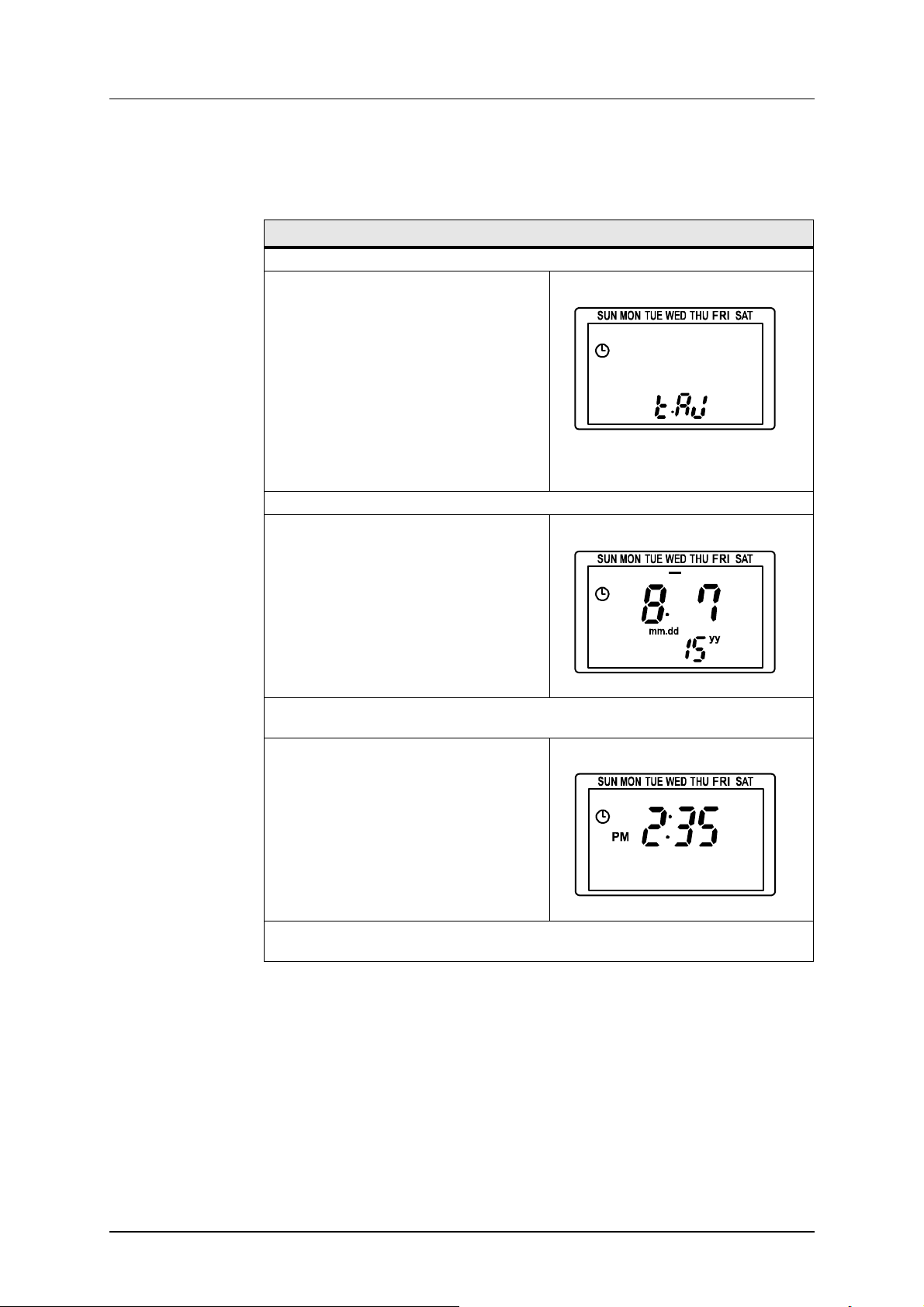
The display’s appearance during operation (normal informa-
ion)
t
When the machine is in operation, the timer’s display looks different depending
on whether the start time is set or not. The display also depends on how the start
time has been set.
When the start time is not set, or when the start time is set for a specific date, the
display appears as above.
The actual time (12-hour clock) is shown on the display. The present day of the
week is shown as a thin line under the name of the day of the week. (If start time
for date is set and this date has expired, the message YEAR is shown to the right
of the time).
When the machine is set to start at a certain time on certain days of the week, the
display appears as above.
The time and day of the week are shown here in the same way as above. The
next upcoming start time is shown too. The time for the next start time appears
under the actual time, and day of the week for the next start time is indicated with
a thicker line under the name of the day of the week.
In both cases, it is possible to see the current date by holding down the button ►
for 3 seconds. The date is then shown for 3 seconds on the display before returning to its state as per the illustrations above.
24
Instructions for use
90-9-05-005
90-9-05-006
90-9-05-007
WD-215T Rev. 6.0 (201812)
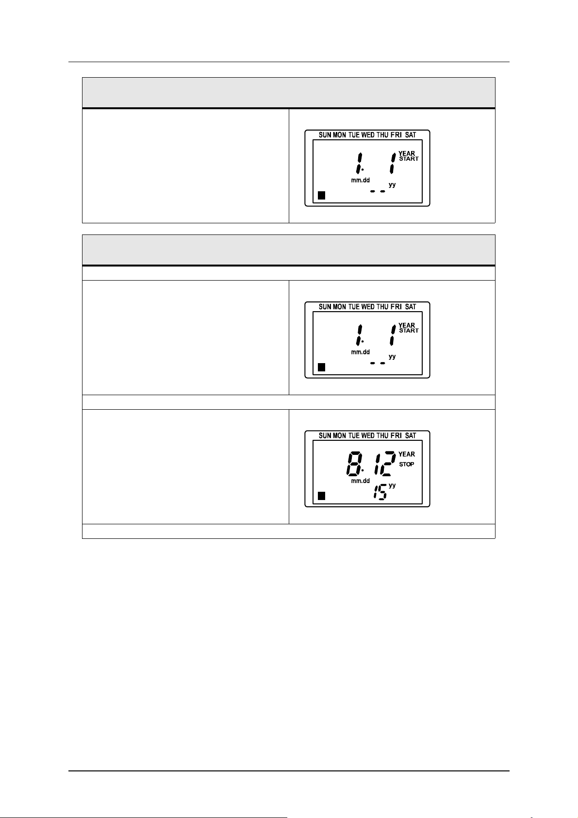
Setting the date and time
For the TimerStart function to work as expected, the date and timer clock must be
set. This is normally done on delivery.
This is what you should do to set the time and date:
Go into settings mode by holding down the MODE and SET buttons for 3 seconds.
• Press the SET button.
The clock symbol in the upper left
lashes
f
Set the date.
• The value that is currently set flashes. Increase or decrease the value
with the buttons ▲ and ▼.
• In order to move on to the next value,
press the button ►.
• When all the values in the image,
(year (yy), month (mm) and day
(dd)), are set - press the SET button.
Set the clock. The clock has a 12-hour display so AM (before midday) and PM (after
midday) must be set.
• The one that is currently set flashes.
Increase or decrease the value with
the buttons ▲ and ▼.
• In order to move on to the next value,
press the button ►.
• Once the clock has been set - press
the SET button.
Hold down the MODE button for 3 seconds in order to return to normal display information.
25

WD-215T Rev. 6.0 (201812)
P
STEP
PULSE
90-9-05-008
P
STEP
90-9-05-026
P
STEP
PULSE
90-9-05-009
Instructions for use
Setting the start time, days of the week
With this setting, you can set a time when the dishwasher begins to fill and heat
the water in the tank, and which days of the week this start time applies to. If you
want the dishwasher to start at another (additional) time, you must set it for this
time too. All weekly settings are active at the same time. For example: The machine should start filling with water and heating at 8.00 on Monday to Friday inclusive
and at 8.45 on Saturday and Sunday. Therefore, it is set to 8.00 for Monday,
Tuesday, Wednesday, Thursday and Friday, and is set to 8.45 for Saturday and
Sunday.
This is what you should do to set the start time and which days of the week it
should apply to:
Access the start time settings mode by pressing the MODE button for 3 seconds.
• Press the SET button.
P down to the left flashes
If there are no previously stored start time settings, the points below must be followed. If start time settings
are stored, the timer moves on directly to the next step (set days of the week):
• Press on either of the buttons ▲ or ▼ so
that the message ON/OFF changes to PULSE.
• Press the SET button.
The message ON/OFF flashes
Set which days of the week the start time should apply to.
To activate the day of the week that the
•
pointer (the thin line under the day of the
week) indicates, press either of the buttons
▲ or ▼. When a thicker line under the thin
flashing line is shown, this day is activated.
• By pressing the button ►, the pointer can
be moved.
• Continue to move and activate with the buttons until all the days of the week which the
start time should apply to have a thicker line
visible under them.
• Once the setting is complete - press the
SET button.
The arrow symbol and the line under the day
of the week flashes
26

WD-215T Rev. 6.0 (201812)
P
STEP
PULSE
90-9-05-010
P
STEP
PULSE
90-9-05-011
Instructions for use
This is what you should do to set the start time and which days of the week it
should apply to:
Set the start time. The value that is currently set flashes.
• Change the flashing value with the buttons
▲ and ▼.
• Move between the settings for the part of
the day (AM / PM), hours and minutes with
the button ►.
• Once the setting of all the values for the
start time are complete - press SET.
The arrow symbol and adjustable value flas-
es
h
Set the pulse length.
• The pulse length should always be set to
1 second. Change the value if necessary
with the buttons ▲ and ▼.
• Press SET when the setting is complete.
Press SET once more.
Hold down the MODE button for 3 seconds in order to return to normal display information.
27

WD-215T Rev. 6.0 (201812)
P
STEP
PULSE
90-9-05-008
P
STEP
90-9-05-012
P
STEP
90-9-05-013
Instructions for use
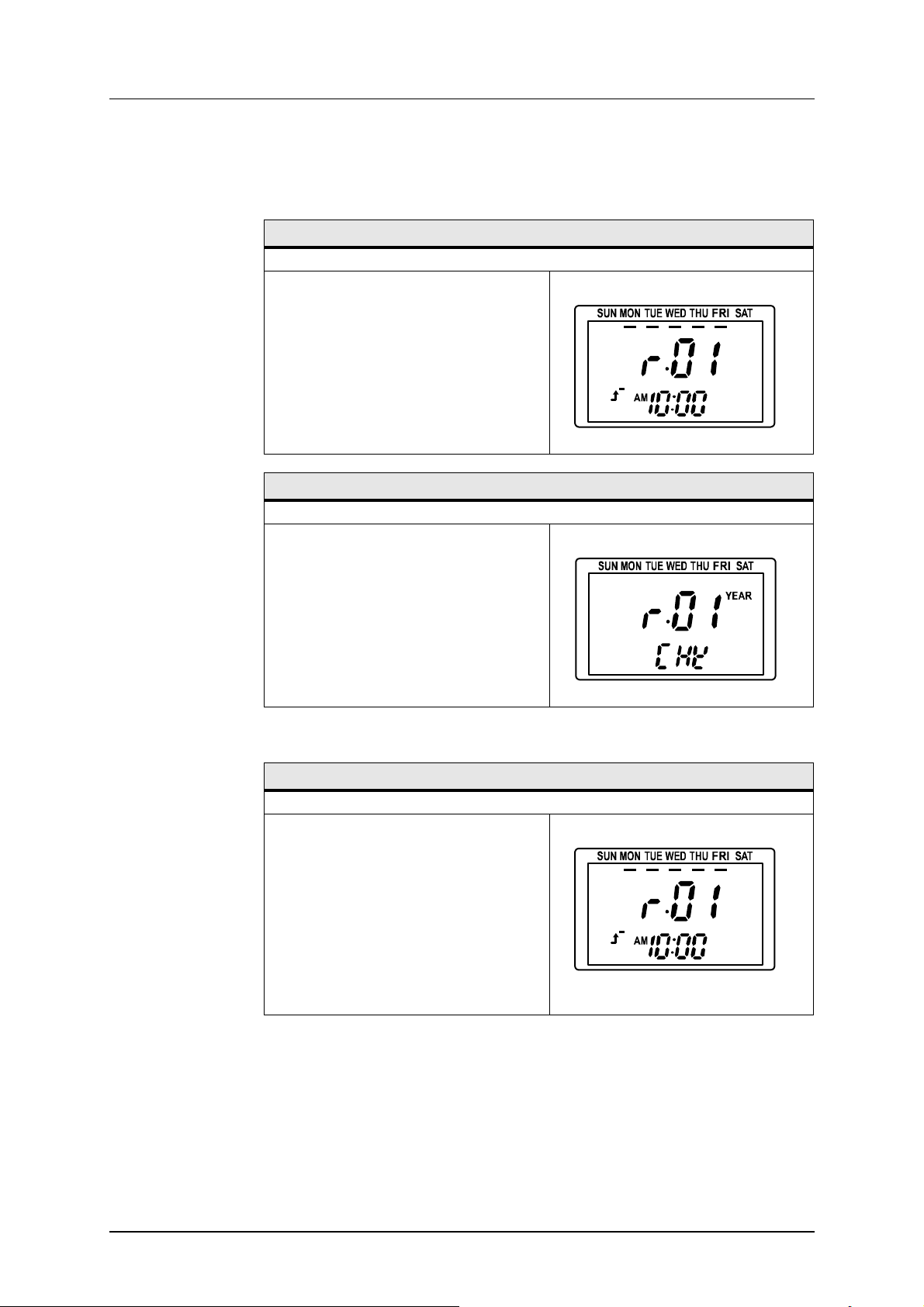
Setting the start time, date
It is possible to set the start time for specific dates, either for an individual date or
for a period between a start date and an end date. It is possible to set the timer
for a date up to two years from the current date.
This is what you should do to set the start time and which dates it should apply
to:
Hold down the MODE button for 3 seconds in order to enter settings mode.
• Press MODE again.
P down to the left flashes
• Press the SET button.
The message YEAR and P down to the left
lashes
f
If there are no previously stored start time settings, the points below must be followed. If start time settings
re stored, the timer moves on directly to the next step (set start date):
a
• Change with the buttons ▲ and ▼ so that
PULSE is indicated instead of ON/OFF.
• Press SET.
The message ON/OFF flashes
Set the start date (adjustable value flashes):
28
WD-215T Rev. 6.0 (201812)
P
PULSE
90-9-05-014
P
PULSE
90-9-05-014
P
PULSE
90-9-05-015
Instructions for use
This is what you should do to set the start time and which dates it should apply
to:
• Change the flashing value with the buttons
▲ and .
• Scroll to the next value with the button ►.
• When all the values (year, month and day)
are set, press SET.
This is what you should do to set the start time and which dates it should apply
to:
Set the stop date (adjustable value flashes):
• Change the flashing value with the buttons
▲ and ▼.
• Scroll to the next value with the help of the
button ►.
• When all the values (year, month and day)
are set, press SET.
Set the start time (adjustable value flashes):
• Change the flashing value with the help of
the buttons ▲ and ▼.
• Scroll to the next value with the help of the
button ►.
• When all the values (before midday (AM)/after midday (PM), hours and minutes) are
set, press SET.
Set the pulse length:
29

WD-215T Rev. 6.0 (201812)
P
STEP
PULSE
90-9-05-017
P
STEP
90-9-05-018
Instructions for use
This is what you should do to set the start time and which dates it should apply
to:
• The pulse length should always be set to 1
second. Change with the help of the buttons
▲ and ▼ if necessary.
• Press SET.
Hold down the MODE button for 3 seconds in order to return to normal information mode.
30
Instructions for use
PULSE
90-9-05-019
PULSE
90-9-05-020
PULSE
90-9-05-019
WD-215T Rev. 6.0 (201812)
Checking, changing and removal of set start time
If the buttons have not been pressed for at least 60 seconds while in check information mode, the display returns automatically to normal display mode.
Checking of set start times, days of the week:
Hold down the CHECK button for approx. 1 second until the display changes state.
• By pressing repeatedly on CHECK,
you can scroll through every set start
time.
• If several start time settings are stored, they are numbered as r01, r02
and so on.
• Once you have scrolled past the last
stored start time, the display returns
to its normal state.
Checking of set start times, date:
Hold down the CHECK button for approx. 3 seconds.
• By pressing repeatedly on CHECK,
you can scroll through every set start
time.
• If several start time settings are stored, they are numbered as r01, r02
and so on.
• Once you have scrolled past the last
stored start time, the display returns
to its normal state.
Changing set start times, days of the week:
Hold down the CHECK button for approx. 1 second.
• Scroll forward to the start time setting to be changed by pressing
CHECK.
• Hold down the SET button for approx. 3 seconds.
The arrow symbol flashes
31

Instructions for use
P
PULSE
90-9-05-021
P
PULSE
90-9-05-022
PULSE
90-9-05-019
PULSE
90-9-05-020
WD-215T Rev. 6.0 (201812)
Changing set start times, days of the week:
• Press the SET button.
Edt flashes
• Set days of the week, start time and
ulse length in the same way as des-
p
cribed above under “Setting the start
time, days of the week”
• The display returns to check information mode when the SET button is
pressed after the pulse length has
been changed.
Arrow symbol and adjustable value
flashes
• You can choose here to scroll further
to the next set start time by pressing
the CHECK button or to exit the
check information mode by holding
down the MODE button for approx. 3
seconds (if the buttons have not
been pressed for at least 60 seconds, the display returns automatically to normal display mode).
Changing the set start times, date:
Hold down the CHECK button for approx. 3 seconds.
• Scroll forward to the start time setting that should be changed by pressing CHECK repeatedly.
• Hold down the SET button for approx. 3 seconds.
32

Instructions for use
P
PULSE
90-9-05-023
P
PULSE
90-9-05-024
PULSE
90-9-05-025
PULSE
90-9-05-019
WD-215T Rev. 6.0 (201812)
Changing the set start times, date:
• Press the SET button.
• Set start date, stop date, start time
nd pulse length in the same way as
a
described under “Setting the start time, date”
• The display returns to check information mode when the SET button is
pressed after the pulse length has
been changed.
Edt flashes
START and adjustable value flashes
• You can choose here to scroll further
to the next set start time by pressing
the CHECK button or to exit the
check information mode by holding
down the MODE button for approx. 3
seconds (if the buttons have not
been pressed for at least 60 seconds, the display returns automatically to normal display mode).
r02 flashes
Removal of set start time:
Start time, day of the week: Enter check mode by holding down the CHECK button for
approx. 1 second.
Start time, date: Enter check mode by holding down the CHECK button for approx. 3
second.
• Scroll forward to the start time setting to be removed by pressing the
CHECK button.
Hold down the SET button for approx. 3 seconds.
33

Instructions for use
P
PULSE
90-9-05-021
WD-215T Rev. 6.0 (201812)
Removal of set start time:
• Change with the help of either of the
buttons ▲ or ▼ so that Clr is indicated under the start time setting number instead of Edt.
Press SET.
Hold down the SET button for 3 seconds in order to return to normal information mode.
34

Instructions for use
4.2 Using the machine
4.2.1 Washing
Before trays are fed into the machine, they must be soaked to remove dried-on
pieces of food.
Push in the trays on the long side first through the feed opening. The belt and the
washing process will start.
For the movement of trays through the machine to continue, new trays must be
fed in all the time. For each tray that is fed in, the belt moves just one short step
and then stops. The next tray that is fed in will start the belt again. When no more
trays are fed in to the machine, it will stop.
For longer periods between washes, the machine should be in the “normal” mode
and closed. This ensures the temperature in the machine is maintained.
WD-215T Rev. 6.0 (201812)
4.2.2 Checking the wash result
The dishware should be checked after each wash for:
PROBLEMS CAUSES & MEASURES
Starch spots • Scraping: Important to remove as much food particles as possible
Misting
Protein residues
Detergent residues
before washing. This also means that the water in the machine
does not need to be changed as often. Scrape better.
• Detergent and drying agent dosage: If using liquid detergent and
drying agent, the same make and type should be used. A service
technician should contacted to rinse the equipment with water
when replacing the detergent and drying agent. The dosing affects
both detergent and drying results of the dishware. The hardness level of the water affects the consumption of detergent. Contact the
detergent supplier.
• Temperatures: At incorrect temperatures the dishes will not be
clean. Contact a service technician if you need to change the set
values.
• Programme selection: Programme with too short a washing time
selected. Choose a programme with a longer washing time.
• Cleaning the machine: Insufficient cleaning of the machine affects the results of the washing. Ensure better cleaning of the
machine.
• Soaking: Items with hard dried food. Soak the dishes in water. Do
NOT use washing-up liquid.
35

Instructions for use
4.2.3 Storage in the tray dispenser
If washed trays are stored in the tray dispenser connected to the machine's outfeed end, a message will appear on the display when the dispenser is full of trays.
Change the dispenser. When an empty dispenser is put in place, the machine is
ready to wash again.
The machine can also be connected to a tray exchanger for two dispensers.
When one dispenser is full, the trays are automatically switched to the other dispenser and the machine does not stop until both dispensers are full.
4.2.4 Changing the water
For best wash results, it is important that the water in the tanks is changed if it
ecomes too dirty. The water should always be changed if foam begins to form in
b
the chemical wash tank.
• Switch the machine off by pressing button (10).
• Remove the filters (19) and empty the machine by turning the level pipe
(22) a quarter of a turn.
• When the tank is empty, close the level pipe and refit the filters.
• Refill the machine with water.
WD-215T Rev. 6.0 (201812)
4.2.5 Emergency stop
The machine will go to an emergency stop if button (11) on the control panel is
pressed. If an emergency stop occurs:
• The problem which caused the emergency stop must be rectified.
• Reset the emergency stop by turning it in the direction of the arrows (clockwise).
• Reset the alarm by pressing button (5).
4.2.6 Unloading trays manually
Manual unloading is used to empty the machine of trays. When the last trays need
o be washed and the machine has stopped, use the manual unloading mode to
t
take the remaining trays out of the machine.
Unload the trays by pressing the button (4).
36

Instructions for use
stalh
4.3 After use
HACCP is a preventive inspection system to ensure hygiene requirements are
met during the washing process and cleaning of the machine. As a result of its
design, the machine meets strict hygiene requirements. Regular, thorough cleaning is also important from a hygiene perspective. A machine that is properly cleaned helps produce a good wash result, reduces the risk of dirt accumulating,
increases the service life of the machine and reduces the risk of emergency shutdown.
• Make sure the power supply to the machine is disconnected and that the
incoming water is turned off during cleaning.
• All internal cleaning can and should take place from the front side of the
machine to avoid the risk of crushing injuries beside the feed cradle.
• If any items become trapped in the feed cradle, these can be released
using a 13mm double-ended spanner to turn the feed crank clockwise.
4.3.1 Incorrect cleaning methods
WD-215T Rev. 6.0 (201812)
NB: An incorrect cleaning method may damage the machine. The following points
ust be observed:
m
• Do NOT use steel wool as it will cause corrosion to form on the machine.
• If detergent is used, it must not contain abrasives. Detergents containing
abrasives will damage the stainless steel panels.
• The exterior of the machine must not be hosed. Water can enter the machine and damage the control panel and electrical equipment. There is a risk
of splashing even if the floor is hosed down.
• Pressure washers can damage the machine and must NOT be used for
cleaning purposes. The supplier cannot be held liable for any faults caused
by the use of pressure washers on the machine and any such use will invalidate the warranty. Never use a pressure washer to clean the floor within
1 metre of the machine.
Steel wool and pressure washers must not be used for cleaning
37

Instructions for use
4.3.2 Daily cleaning
Internally
• Unhook the curtains (17) at the infeed end and wash them in a basket.
• Switch the machine off by pressing button (10).
• Empty the tank by turning the level pipe (22) a quarter of a turn.
• Clean the filters (19), the curtains (17), the level pipe (22), the outlet seals
• Clean the washer arm nozzles (16).
• Clean the doors (23). Wipe the rubber strips on the doors which are fitted
• Rinse out all of the machine’s inside surfaces and clean the tank.
• Finally, clean the filter (26).
• Empty the final rinse tank and clean the filter (25). The filter is placed be-
• Refit the components.
• Leave the doors open.
WD-215T Rev. 6.0 (201812)
(24) and the rinse nozzles (15). Never leave the level pipe so that the rubber sleeve rests on a surface. The sleeve can become deformed leading to
the risk of water leakage in the tank.
at the top of the back of the doors. Always leave the doors open after cleaning the machine.
hind the lower door at the outfeed end.
Cleaning the filter
The final rinse tank must be empty when the filter (25) is cleaned otherwise water
ill leak into the dish-washing room when the filter is unscrewed. The tank must
w
be emptied in connection with daily cleaning.
• Unscrew the cover (C) and remove the filter (B). Rinse the filter and cover.
• When refitting, it is important to fit the filter correctly to ensure that it is not
damaged and that no leakage occurs.
• First fit the filter (B) in the filter housing (A) then ensure that it is sitting
straight.
• Fit the cover (C), (does not need to be screwed tight).
38

Instructions for use
Rec.filter
A
C
B
WD-215T Rev. 6.0 (201812)
Removing/fitting the filter
A=Filter housing
B=Filter
C=Cover
Externally
Wipe the outside of the machine with a soft, damp cloth.
4.3.3 Cleaning and checking each week or as required
Weekly cleaning should be more thorough than daily cleaning. In addition to the
aily cleaning measures, clean the machine as per these instructions:
d
• Clean the washer arms (16). Undo the lock by the back edge of the washer
arm and pull the washer arm out. Brush and rinse the inside of the washer
arms and clean the nozzles.
• Clean the grille for the drying zone fan (12).
• Check and clean the rinse nozzles (15).
• Check that the overload switch for the feed is working by attempting to hold
the belt still for a few seconds during operation. If the switch does not activate (the belt should stop), it must be adjusted immediately.
• Remove the doors (23). Open the door, depress the door lock (13) and lift
the door vertically. Clean the doors.
• Decalcify the machine when necessary.
• Refit all cleaned components.
39

Instructions for use
WD-215T Rev. 6.0 (201812)
Cleaning brush WD721.0301
The door springs may be cleaned as required by rinsing these from the side using
a hose. The springs must NOT be removed! The door in front of the spring being
cleaned must be closed.
40
WD-215T Rev. 6.0 (201812)
B
C
A
F
E
ICS_ESP_04_R1
D
Instructions for use
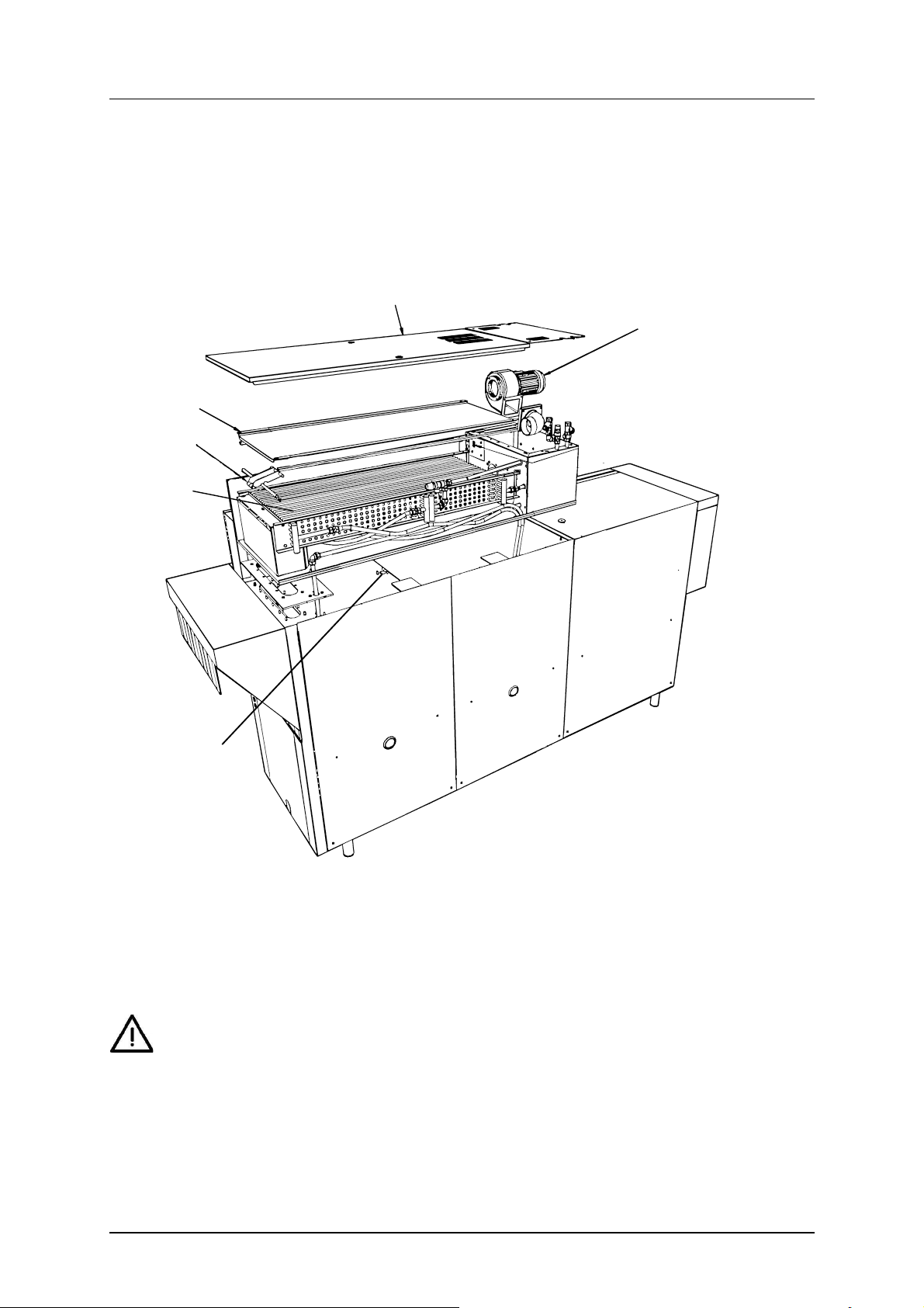
4.3.4 Cleaning in the event of an alarm or 1 time / year
The machine's condensing battery (D) must be cleaned at least once a year or
when an alarm with a message about cleaning the battery appears on the control
panel display.
A=Top panel
B=Cover plate
C=Lifting arm
D=Condensing battery
E=Drain
F=Fan motor
NB: When cleaning the condensing battery and the base of the battery box, do
not use more water than the drain (E) under the battery can remove from the
machine. The battery must be cleaned with hot water at normal pressure. Do not
aim the water directly at the fan motor (F) on the end piece of the battery. The
electric motor may be damaged if it is rinsed with high-pressure water.
• Remove the top panel (A) on the condensing battery box.
41
Instructions for use
• Remove the cover plate (B) from the condensing battery by unscrewing the
wing nuts which fasten it in place. Lift up the condensing battery using the
lifting arm (C) to make it easier to remove.
• Check from inside the machine that the drain (E) under the battery is not
blocked.
• With the condensing battery removed, begin by cleaning the bottom plate
of the battery box. Then check that the drain (E) is not blocked.
• Next, clean the condensing battery (D). Rinse between the cooling fins
from above. If the condensing battery is very dirty, a cleaning product with
a neutral pH which will dissolve grease can be used. Check the drain.
• Finish by washing the base of the battery box again.
• Replace the condensing battery using the lifting arm (C), attach the cover
plate securely (B) using the wing nuts, before fitting the top panel (A).
4.3.5 Operating problems
Check:
WD-215T Rev. 6.0 (201812)
• H
as the appliance been used according to the instructions?
• Are all the removable parts in their correct place?
• Is the main switch in the ON position?
• Are there any error messages on the display?
• Are the fuses in the electrical cabinet still intact? Ask service personnel to
check the fuses.
Error messages
Machine faults and user faults are indicated by messages on the display (1). The
alarms indicated with a flashing LED (8) can be reset by pressing button (9) when
the cause of the alarm has been rectified.
The following alarms can be addressed by the operator. For other alarms, or if an
alarm reset with button (9) recurs, authorised service personnel must be contacted.
ALARM MESSAGE ACTION
(0)
PLATFORM ERROR
(63) POWER SUPPLY
FAILURE
CHECK THE
EMERGENCY SWITCH
(98) HARDWARE ERROR
POWER ON FUNCTION
DEFECT
CALL SERVICE
(1)
EMERGENCY STOP
ACTIVATED
Restart the machine.
Reset the emergency stop by turning it in the direction of the arrows. Restart the
machine.
Restart the machine. If the error recurs, contact an authorised service company.
Reset the emergency stop by turning it in the direction of the arrows. Start the
feed by pressing button (5).
42

Instructions for use
ALARM MESSAGE ACTION
(100)
NOMINAL VALUES
RESTORED FROM UI
(4)
COMMUNICATION
ERROR BETWEEN
CPU AND I/O 1
CALL SERVICE
(5)
COMMUNICATION
ERROR BETWEEN
CPU AND I/O 2
CALL SERVICE
(6) COMMUNICATION
ERROR BETWEEN
CPU AND EXTRA CARD
CALL SERVICE
(7) COMMUNICATION
ERROR BETWEEN
CPU AND DISPLAY CARD
CALL SERVICE
(14) WEAK SIGNAL
FROM PHOTOCELL
START WASH
CLEAN PHOTOCELL
(47) HACCP ALARM
PUMP FUNCTIONALITY
DEFECT
PRESS RESET
(64) HACCP ALARM
WRONG TEMPERATURE
IN TANK
PRESS RESET
(67) HACCP ALARM
WRONG TEMPERATURE
IN BOILER
PRESS RESET
(72) HACCP ALARM
WASHING DETERGENT
FUNCTIONALITY DEFECT
PRESS RESET
(78) HACCP ALARM
FINAL RINSE
DEFECT
PRESS RESET
(29)
EXTERNAL ALARM
INPUT ACTIVATED
(30)
TIMEOUT FILLING
OF TANKS
PRESS RESET
Reset the alarm by pressing button (9). If the error recurs, contact an authorised
service company.
Restart the machine.
Restart the machine.
Restart the machine.
Restart the machine.
Clean the photocell. The alarm in the display will disappear after cleaning.
Reset the alarm by pressing button (9). If the error recurs, contact an authorised
service company.
Reset the alarm by pressing button (9). If the error recurs, contact an authorised
service company.
Reset the alarm by pressing button (9). If the error recurs, contact an authorised
service company.
Check and fill with new detergent. Reset the alarm by pressing button (9).
Open the tap. Clean the nozzles. Reset the alarm by pressing button (9).
Reset the alarm by pressing button (9). If the error recurs, contact an authorised
service company.
Open the stopcocks. Close the level pipe and the outlet seals. Check the rubber
sleeves. Reset the alarm by pressing button (9).
WD-215T Rev. 6.0 (201812)
43

Instructions for use
ALARM MESSAGE ACTION
(31)
TIMEOUT HEATING
TANKS AND BOILERS
PRESS RESET
(33)
DOOR IS OPEN
CLOSE DOOR
(41)
LOW LEVEL IN TANK 2
(CHEM WASH TANK 1)
(51) OVERLOAD
FEEDING ACTIVATED
REMOVE OBJECT
RESTART FEEDING
(85)
OVERLOAD FEEDING
ACTIVATED
PRESS RESET
(52) FEEDER LIMIT
SWITCH ACTIVATED.
REMOVE OBJECT FROM
THE FEEDER LIMIT
(54) TRAY DISPENSER
OUT OF POSITION
CHECK
TRAY DISPENSER
(61)
LOW TEMPERATURE
IN TANK 2
(CHEM WASH TANK 1)
(62)
LOW TEMPERATURE
IN TANK 3
(CHEM WASH TANK 2)
(81)
LOW TEMPERATURE
IN TANK 4
(CHEM WASH TANK 3)
(66)
LOW TEMPERATURE
IN THE FINAL RINSE
BOILER
(71) WASHING DETERGENT ALARM ACTIVE
CHECK DETERGENT
DEVICE
(77)
FINAL RINSE ERROR
SENSOR ERROR
FLOW METER BV02
(76)
FINAL RINSE ERROR
NO FLOW IN
THE MACHINE
Reset the alarm by pressing button (9). If the error recurs, contact an authorised
service company.
Close the door and start the feed by pressing button (5).
Close the level pipe or the outlet seal. Check the rubber sleeve.
ove the item. Start the feed by pressing button (5).
Rem
Reset the alarm by pressing button (9).
Remove the basket. The feed will start automatically.
Adjust the dispenser if it is in the wrong position or connect an empty dispenser
to the machine or tray exchanger.
Reset the alarm by pressing button (9). If the error recurs, contact an authorised
service company.
Reset the alarm by pressing button (9). If the error recurs, contact an authorised
service company.
Reset the alarm by pressing button (9). If the error recurs, contact an authorised
service company.
Reset the alarm by pressing button (9). If the error recurs, contact an authorised
service company.
Check and fill with new detergent.
Reset the alarm by pressing button (9). If the error recurs, contact an authorised
service company.
Check that the stopcocks on the incoming water supply are open. Reset the
alarm by pressing button (9). If the error recurs, contact an authorised service
company.
WD-215T Rev. 6.0 (201812)
44

WD-215T Rev. 6.0 (201812)
Instructions for use
ALARM MESSAGE ACTION
(75)
FI
NAL RINSE ERROR
LOW FLOW IN
THE MACHINE
(90)
ADJUSTED MACHINE
CAPACITY OVERRIDDEN
(83) TIME FOR
MAINTENANCE
CONTACT:
Clean the nozzles. Reset the alarm by pressing button (9). If the error recurs,
contact an authorised service company.
Leave more time between feeding in trays.
Reset the alarm by pressing button (9). If the error recurs, contact an authorised
service company.
Troubleshooting
In addition to the faults shown on the control panel other faults can occur. The table below shows some faults which can be rectified by the operator. If the problem
persists, contact authorised service personnel.
Troubleshooting
Problem Cause Action
No indication on the control panel
display when the power is switched
on.
The machine does not fill with water. The shut-off cock on the incoming
The machine does not stop filling. Level pipe (22) is not in place. Fit the level pipe.
Washing pump is noisy. Low water level in the tank. Check that the level pipe is closed.
The machine is not cleaning properly.
The trays do not dry. The rinsing nozzles (15) are block-
The main switch is off. Turn on the mains switch (14).
Open the tap.
water supply is closed.
The level pipe's rubber sleeve is not
sealing against the bottom plate.
Foam in the tank. Change the water.
The rinsing and washing nozzles are
clogged with dirt.
There is too little detergent. Check the amount of detergent.
Foam forming in the washing tank. Check that the washing temperature
Dirt has dried on the trays. Soak the trays before washing.
The water in the tank is too dirty. Change the water.
ed.
Too little drying agent. Check the quantity of drying agent.
Check that the level pipe is closed.
Change the rubber sleeve if it is damaged.
Change the rubber sleeve if it is damaged.
Check and clean the nozzles.
is not too low and that the correct detergent is being used. Change the
water if foam forms.
Check and clean the nozzles.
When you contact service personnel, you will need to provide the following information:
• Machine model
• Machine serial number and date when the machine was installed.
• A brief description of the problem.
• What happened immediately before the fault occurred
45

Technical information
The manufacturer reserves the right to make changes to the technical data.
Technical data
Pump motor chemical wash (kW) 1.5
Pump motor, recirculating rinse (kW) 0.11
Condensing fan (kW) 0.12
Drying zone fan I (kW) 1.1
Drive motor, belt (kW) 0.12
Booster heater (kW) 12
Pump motor, final rinse (kW) 0.11
Tank heater (kW) 12
Heater, drying zone (kW) 6
Heat recovery, cooling surface (m²) 25
Condensing fan, capacity (m³/hour) 100
Tank volume (litres) 100
Tank volume, final rinse tank (litres) 4
Weight, machine in operation (kg) 620
Enclosure protection class (IP) 55
WD-215T Rev. 6.0 (201812)
5. Technical information
Capacity and operating data
Capacity (trays/hour) 9
Max. tray size (mm) 530x330
Cold water consumption final rinse (litres/hour) 150
Steam consumption at 150 - 250 kPa (kg/hour) * 40
Steam consumption at 50 - 140 kPa (kg/hour) * 40
Sound pressure level, LPA (dBA) ** 69
Sound power level LWA (dBA) ** 83
* When the machine is steam-heated
** in accordance with EN 60 335-2-58, §ZAA.2.8 with instruments that satisfy
class 1.
Measurements of the sound pressure level on site are performed in three places
20 cm from the edges of the front at a height of 1.55 m using a microphone.
When measuring sound power level, create an imaginary measurement area
consisting of five sides at a distance of 1 m from all edges of the machine.
60
Connection, electrically-heated machines
Total connected power (kW) 36
Main fuse 400 V 3N~ (A) * 63
ax. connection area 400 V 3N~ (L1-L3, N, PE) Cu (mm²) 35
M
Main fuse 230 V 3~ (A) * 125
46

Technical information
Connection, electrically-heated machines
Max. connection area 230 V 3~ (L1-L3, PE) Cu (mm²) 70
* Other voltages on request
Connection, steam-heated machine 50-140 kPa
Total connected power (kW) 12
Main fuse 400 V 3N~ (A) *
Max. connection area 400 V 3N~ (L1-L3, N, PE) Cu (mm²) 35
Main fuse 230 V 3~ (A) *
Max. connection area 230 V 3~ (L1-L3, PE) Cu (mm²) 35
Steam connection (internal thread) R¾"
Condensing water connection (internal thread) R½"
* Other voltages on request
Connection, steam-heated machines 150-250kPa
Total connected power (kW) 12
Main fuse 400 V 3N~ (A) * 32
Max. connection area 400 V 3N~ (L1-L3, N, PE) Cu (mm²) 35
Main fuse 230 V 3~ (A) *
Max. connection area 230 V 3~ (L1-L3, PE) Cu (mm²) 35
Steam connection (internal thread) R¾"
Condensing water connection (internal thread) R½"
WD-215T Rev. 6.0 (201812)
32
35
35
* Other voltages on request
Water, drain and ventilation connections
Water quality (hardness ) (°dH) 2-7
Hot water connection, 50-65°C (internal thread) R½"
Cold water connection, 5-12°C (internal thread) R½"
Drain connection, PP - pipe (ø mm) 50
Water capacity, cold water, pressure (kPa) 250-600
Water capacity, cold water, flow (litres/minute) 6
Water capacity, hot water, min./max. pressure (kPa) 100/600
Floor drain, capacity (litres/sec.) 3
Heat load room, sensitive (kW) 4.5
Heat load room, latent (kW) 3
Heat load room, total (kW) 7.5
Capacity heat recovery fan (m³/hour) 100
Size and weight for transport
Size * ( LxWxH ) (m) 2.7x0.8x2.0
Weight * (kg) 510
** Including packaging
47

 Loading...