

Page 1

WET Labs Archive File Processing
User’s Guide
WET Labs, Inc.
PO Box 518
Philomath, OR 97370
(541) 929-5650
www.wetlabs.com
WAP User’s Guide (WAP) Revision E4 19 June 2006
Page 2

Page 3

Table of Contents
1. Overview .................................................................................... 1
1.1 User’s Guide Organization.....................................................................1
2. Setting up Processing Parameters .............................................. 3
2.1 Create Folder Structure .........................................................................3
2.2 Check and Extract Raw Data.................................................................3
2.3 Create WAP Setup Files........................................................................4
2.4 Merge File Pairs ..................................................................................11
3. Reference ................................................................................. 13
3.1 Menu Items..........................................................................................13
3.2 Instrument Selection ............................................................................14
3.3 Extraction Setup File ...........................................................................16
3.4 Merge Setup File .................................................................................18
4. WAP Data Processing Summary............................................... 23
Appendix A: ASCII Data Processing................................................ 25
Device Files.....................................................................................................25
Appendix B: WAP Meter Types ....................................................... 29
WAP User’s Guide (WAP) Revision E4 19 June 2006 i
Page 4

Page 5

1. Overview
The WET Labs Archive Processing program (WAP) provides primary processing of data files
created by Data Handlers (DH-4s) and ac-9 Plus meters. This primary processing consists of
extracting time-stamped raw data from the archive files and applying calibration coefficients to the
data for all WET Labs instruments and selected instruments from other manufacturers.
WAP processes data from archive files that have a *.000 (three-digit) filename suffix. WAP
creates an Instrument Selection File for each “channel” of data, applying user-selected device
and/or calibration files. It then creates an Extraction Setup File with user-defined parameters
about how archive file will be processed. Last, an optional Merge Setup File applies time and/or
depth adjustments to processed data and combines/re-orders the data from one or more of the
“channels” of data into single files.
Secondary data processing such as data binning, quality control checks on data, statistical analysis,
etc. is not provided by WAP.
1.1 User’s Guide Organization
Section 1, Overview
Section 2, Setting up WAP: Step-by-step instructions for processing data in WAP.
Section 3, Reference: Details on WAP menus and setup options.
Section 4, Summary: Single-page “quick start” setup steps, with worksheet.
WAP User’s Guide (WAP) Revision E4 19 June 2006 1
Page 6

2 WAP User’s Guide (WAP) Revision E4 19 June 2006
Page 7
2. Setting up Processing Parameters
This section provides step-by-step instructions for using WAP to process data generated by an
example system consisting of an ac-s, ac-9, CTD, ECO BB9, and WET Labs Flow Sensor.
2.1 Create Folder Structure
Creating the folder structure listed is not required, but it will help a great deal to keep the
numerous files organized.
•
Create a folder and copy DH-4 or ac-9 Plus archive files you wish to process into
that folder.
•
Create a folder and copy all the device files and any ac meter correction files for
each meter’s data you wish to process into that folder.
•
Create a folder to contain data files processed (“extracted”) by WAP.
The main window will display the path of
each file and folder. WAP generated:
•
Instrumentation Selection File
•
Extraction Setup File
•
Merge Setup File
User-generated:
•
Folder to store DH-4/ac-9Plus-generated archive files in for processing by WAP.
•
Device File Folder
•
Output File Folder
2.2 Check and Extract Raw Data
Follow the steps below to view “raw” archives as a data check. Note that for ac meters, the
raw output will be binary.
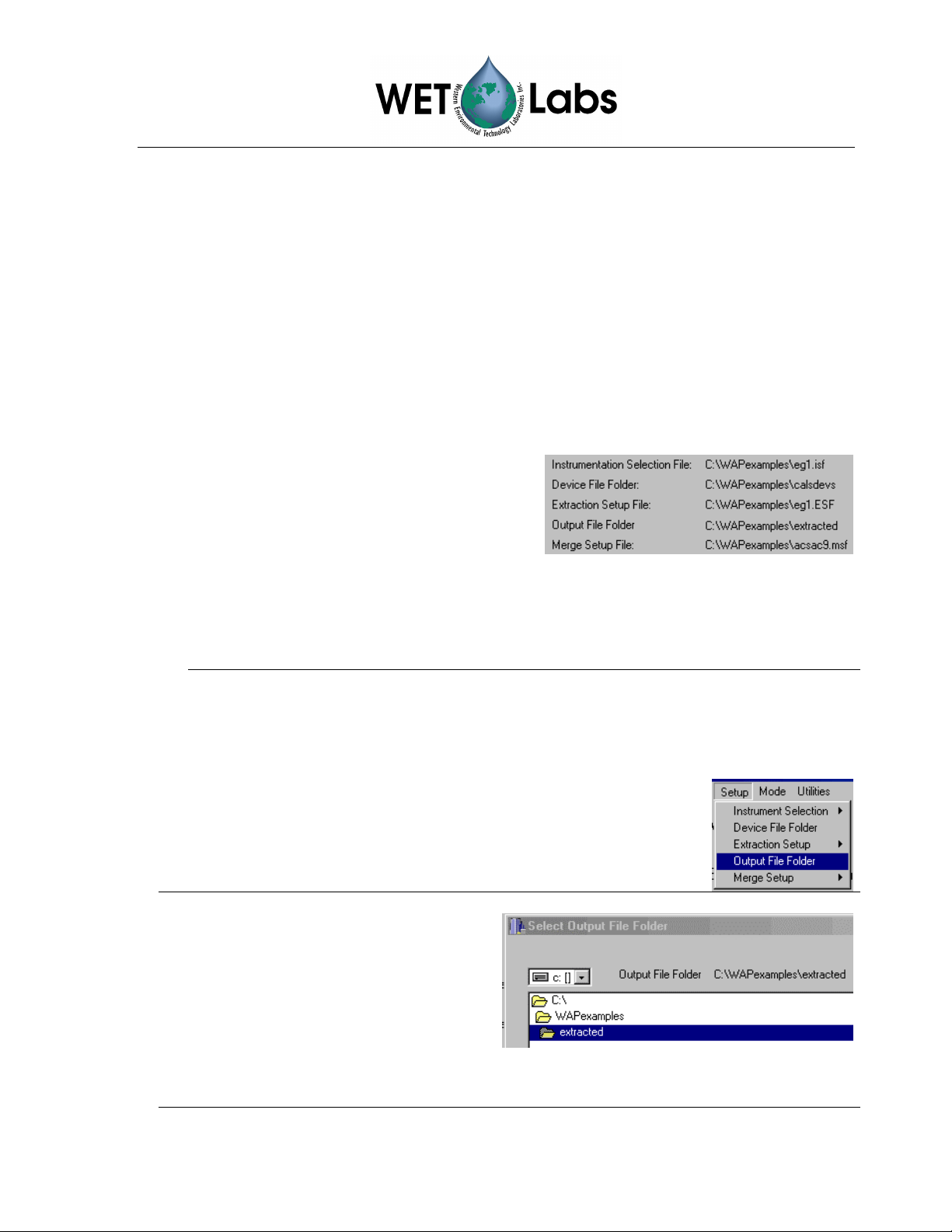
1. Select the Setup pull-down menu,
then Output File Folder.
2. In the resulting window, navigate to
and double-click on the folder in
which you want to store the
raw_archive files WAP will create
(example at right).
Note that this path and folder name
will also be indicated on the main
WAP screen as Output File Folder.
WAP User’s Guide (WAP) Revision E4 19 June 2006 3
Page 8
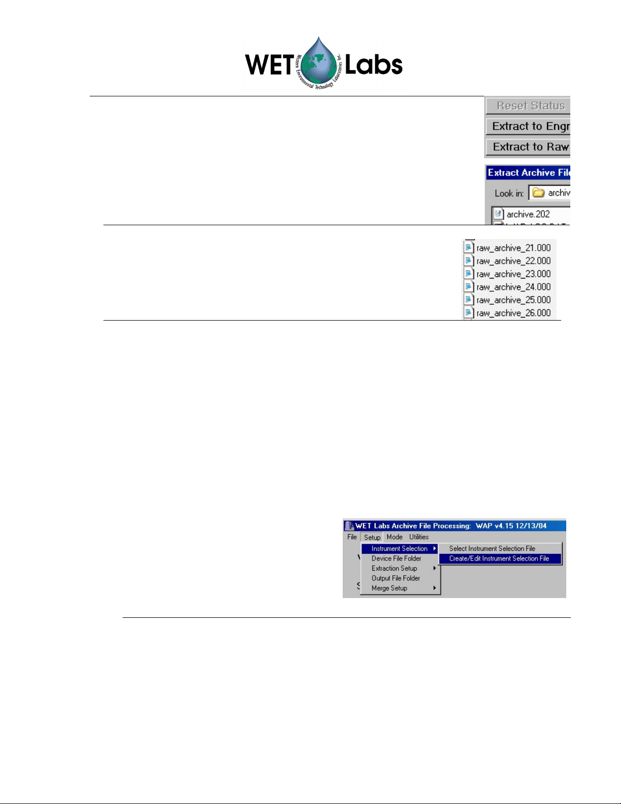
3. Select the Extract to Raw button on the main WAP screen. The
Status indicator will change from Ready…
to Done With Raw Extraction when WAP is finished.
4. In the resulting window, navigate to the folder in which you have
saved the DH-4 or ac meter archive data files and select the desired
run you wish to check.
5. WAP names the resulting files, adding “raw” and appending the
meter’s WAP ID number to the filename.
6. View the raw_archive file(s) to verify the data appears
reasonable.
2.3 Create WAP Setup Files
WAP will further processes archive data and apply necessary corrections, calibration and
device file information. This will allow you to obtain data in engineering units, and
eventually merge this data with other meter data files. from the DH-4 or ac9 Plus archive
files.
2.3.1 Instrument Selection File
The *.isf files contain setup information regarding a specific meter and its associated
calibration and/or device file. Once created and saved, these setup files can be re-used
for processing other meter data files using WAP.
1. Start WAP if necessary.
2. Select Setup / Instrument Selection
> Create/Edit Instrument
Selection File.
To open an existing ISF file that
needs no modifications, choose
Select Instrument Selection File.
4 WAP User’s Guide (WAP) Revision E4 19 June 2006
Page 9
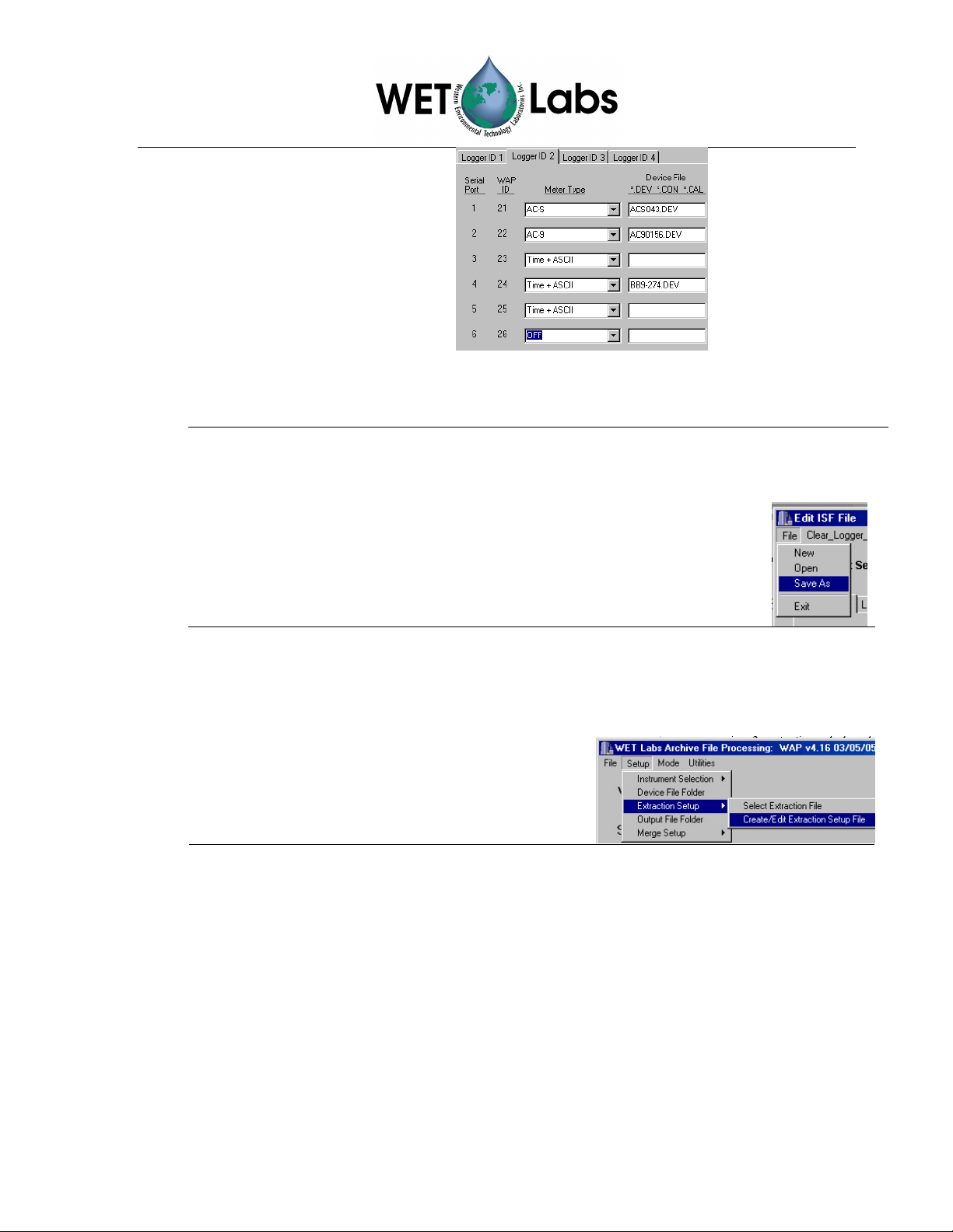
3. Select Meter Type and
enter a device file name if
one is required.
If you do not wish to
process data from one or
more channels, leave the
meter selection OFF. Note
that if a Meter Type is
selected (not set to OFF), an
output file will be created
Serial
Port
WAP
1
2
3
4
5
6
ID
21
22
23
24
25
26
Meter
ac-s
ac-9
CTD
BB9
Flow
Sensor
OFF
whether or not a meter is
physically present.
Tip
Using the worksheet in Section 4 may help keep setup parameters organized.
4. After each of the Meter Type and Device File entries have
been completed, save the settings. The saved *.isf and path
will display on the main WAP window.
2.3.2 Extraction Setup File
Creating an *.esf provides WAP with the parameters (file type, output, and time stamp)
for processing an archive file.
1. Select Setup / Extraction Setup >
Create/Edit Instrument Selection File.
To open an existing *.esf that needs no
modifications, choose Select Extraction File.
WAP User’s Guide (WAP) Revision E4 19 June 2006 5
Page 10
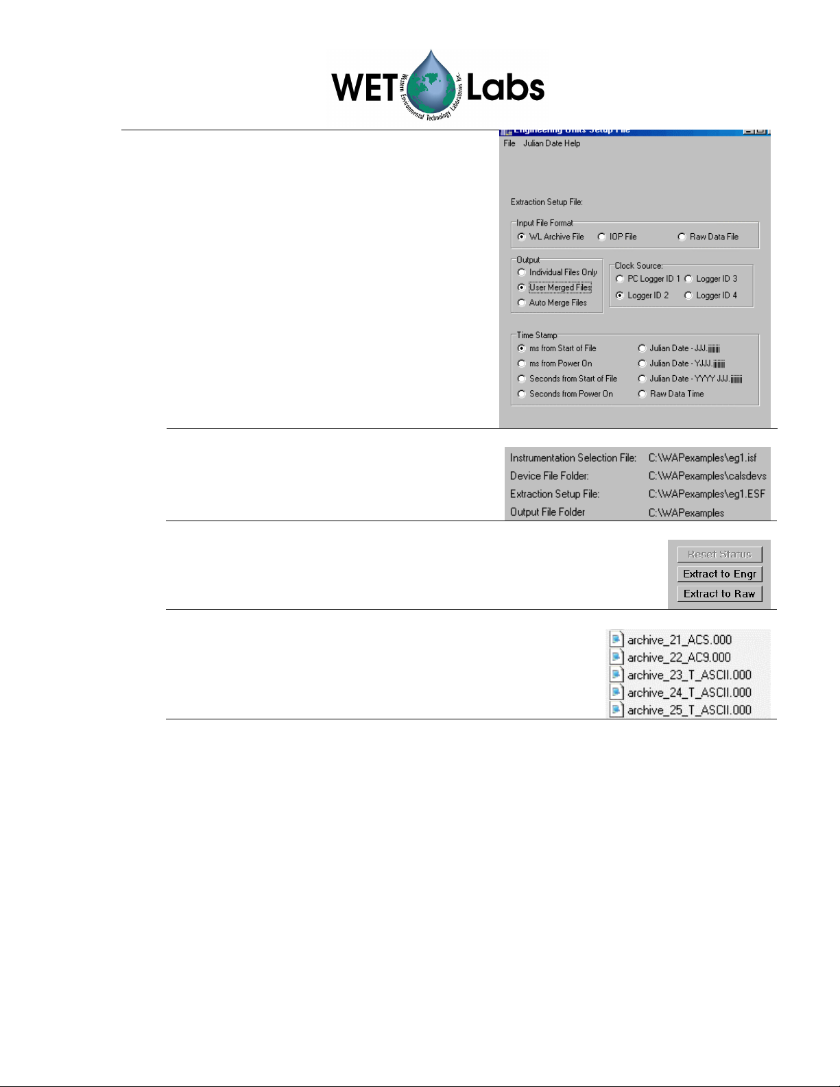
2. Select WL Archive File (default setting)
in the Input File Format area of the
resulting window.
3. Select User Merged Files in the Output
area.
4. Select Logger ID 2 (default setting) in the
Clock Source area.
5. Select ms from Start of File (default
setting) in the Time Stamp area.
6. Use the File pull-down menu to save these
settings.
7. The saved *.esf and path will display at the
main WAP window. This file can be used
for subsequent file extractions.
8. At the main window, select Extract to Engr, then
the archive file. In this example, it’s archive.202.
WAP generates a new file for each instrument, adding the
WAP ID # to the filename. These files will be saved at the
location shown for the Output File Folder on the main screen
(This is a user-specified folder as created in section 2.1.)
2.3.3 Merge Setup
The Merge Setup File (*.msf) controls the final portion of the WAP merging
process. This data merging occurs at the end of the archive file extraction process
and is used to create merged files that contain the data from multiple instruments
that is time/depth-aligned.
WAP file merging is executed as series of sequential file merges performed on two
files at a time. The merge routines sequentially step through pairs of files, with each
step resulting in a merged file called pair.xx. Each pair of files consists of a “base”
file and a “merge” file. The base is used to determine the time/depth resolution for
the merged pair.
Each pair can build upon the previously created pairs. For example, if the first merged
pair contains data from an ac-9 and a CTD, the next merged pair could add the data
from a second ac-9, creating a merged file with data from two ac-9s and a CTD.
6 WAP User’s Guide (WAP) Revision E4 19 June 2006
Page 11
At the basic level, the user
• Selects the “base” and a “merge” pair of files to merge.
• Identifies whether the files will be merged using depth or time.
• Identifies the depth or time columns in the base and merge files.
• Sets the time or depth corrections (if any) for both the base and merge file.
• Selects the number of rows of header information in both base and merge files.
• Sets up any special ac meter data processing.
• Identifies analog channels, if any.
• Formats the output records.
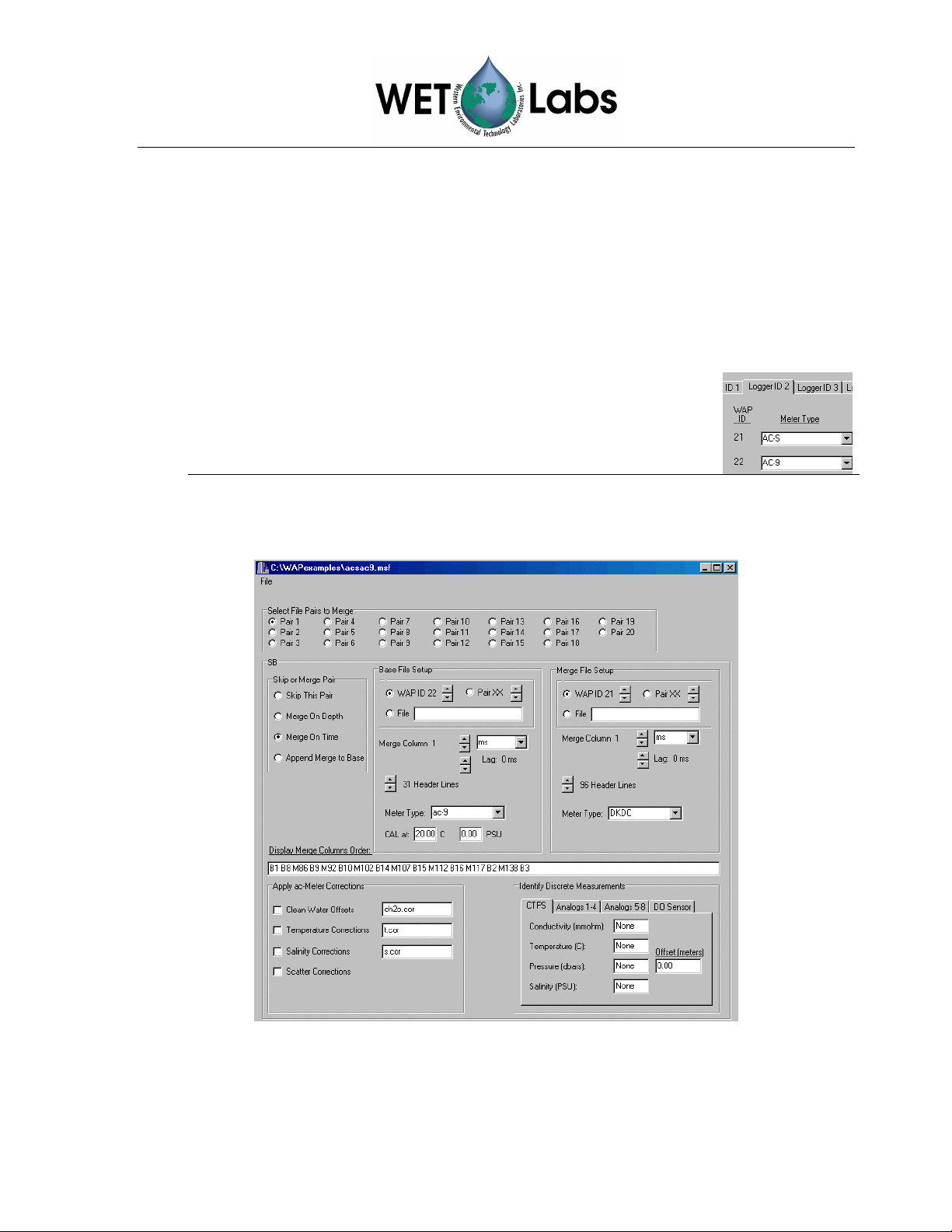
In the following example, the ac-s file (WAP ID 21) will be
merged with the ac-9 “base” file (WAP ID 22). This will result in
Pair 01.
The figure below shows all selections for merging WAP ID 21 with WAP ID 22 to form
Pair 01. Details follow.
1. Select Setup / Merge Setup > Create/Edit Merge Setup File to create a new
Merge Setup File.
WAP User’s Guide (WAP) Revision E4 19 June 2006 7
Page 12
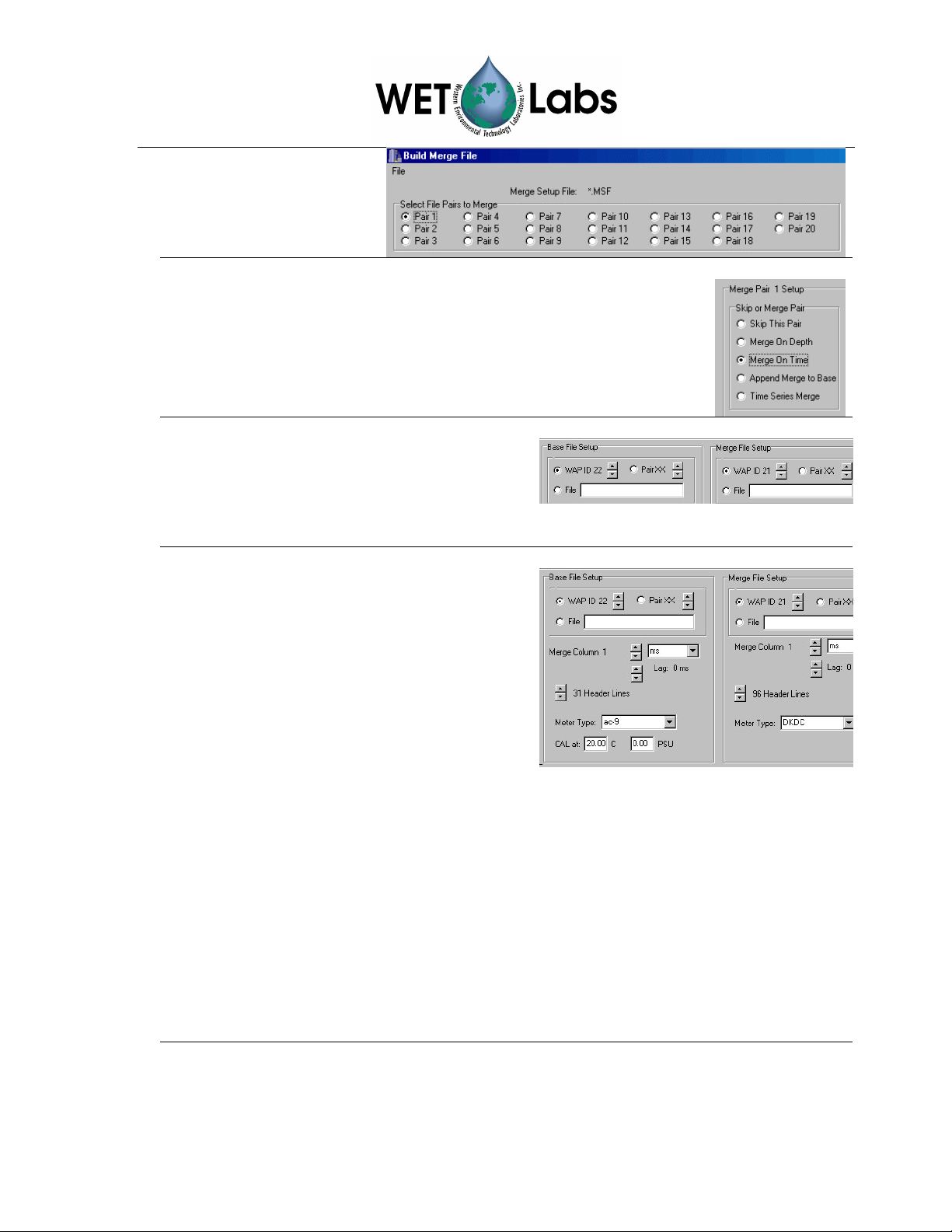
2. Select Pair 1. These
will be the first files
merged.
3. Select Merge On Time. The Base File Setup and the
Merge File Setup boxes will appear.
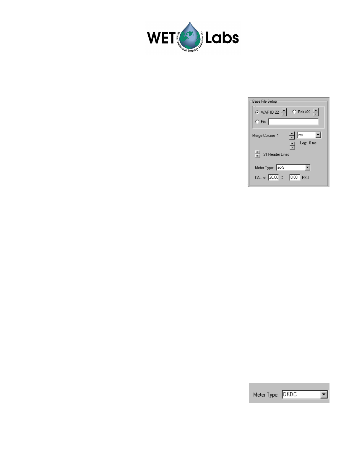
4. Under Base File Setup and Merge
File Setup, use up and down arrows to
select the ID # associated with the
Meter Type assigned in the *.isf
window.
5. In the Merge Column areas under
Base File Setup and Merge File
Setup, use the arrows to select the first
column of data you wish you to merge
(typically column 1). Do this for Base
File Setup and Merge File Setup.
6. The time/date pulldown menu can be
left at ms and the Lag at 0.
7. Scroll to select the number of header
lines in the meter’s output file. WAP
will process data beginning on the next
row.
8. Select the Meter Type: If one of the meters is an ac-9 or ac-s, select ac9 as the
meter type. Otherwise, leave as DKDC (Don’t Know, Don’t Care).
Note that it is only necessary to input the number of header lines for the first pair of
merged files; WAP includes only one header row for each subsequent file/pair.
8 WAP User’s Guide (WAP) Revision E4 19 June 2006
Page 13
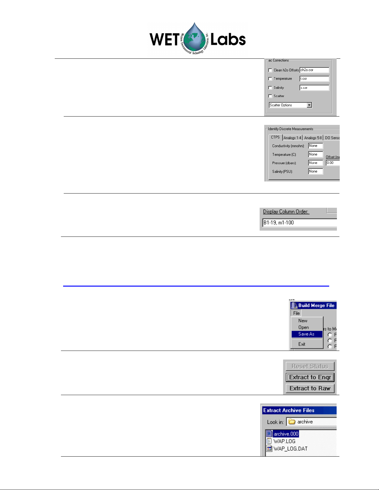
9. Selecting a meter as ac9 will display the ac Corrections
portion of the window, allowing you to input clean water,
temperature, salinity, and scattering corrections. See the
appropriate sections below for details.
10. You can still apply a depth offset to the output records
(see section 3.4):
a. identify a base or merge column as the depth under
the CTPS/Pressure setting, OR
b. input a HAD value in the second location on the
CTPS pressure setting line, OR
c. input “iPres” (insert Pressure) as an item in the
Display Column Order area (see below).
11. Input the columns to be displayed after merging.
B1–19 is a “base” file, ac-9 columns 1 through 19.
M1–100 is a “merge” file, ac-s columns 1 through 100.
Note
In practice, setting up a complex file merge will take several iterations to get all the
column selections and merge options set correctly. WET Labs recommends you
attempt to set up one or two pairs of files at a time, making sure they are correct before
setting up additional pairs that may be dependent on earlier merges.
12. Save the settings for the first pair of files (ac-9 and ac-s): go
to File / Save As. Name the file in the resulting window.
13. In the main WAP window, click the
14. In the resulting window, select the archive.000 file.
15. The status display in the main window will display
Ready . . .
with
while WAP processes the file, then Done
Extraction
. The file archive_pair_01.000 will
be added to the designated output folder.
WAP User’s Guide (WAP) Revision E4 19 June 2006 9
Extract to Engr
button.
Page 14

16. Locate the newly created archive_pair_01.000 (in this
example, it’s in the “extracted” folder set up to contain
all WAP-generated data files.) The .000 files may be
opened in a text-view program such as Notebook, or in
MS Excel.
Following the steps in this section, then, will have generated
•
raw_archive_WAP ID#_Meter Type.000 files, in
which ASCII data can be verified.
•
archive_ WAP ID#_Meter Type.000, which contain
processed data.
•
(Section 2.4: archive_pair_01.000, which in this
example is merged ac-s and ac-9 data.)
The example archive Pair 01 is a bit more complex than merging entire files, but
demonstrates the program’s functionality and is the basis for creating Pair 02 discussed in
Section 2.4.
B1 B8 are “base” files, ac-9 columns 1
and 8.
M86 is a “merge” file, ac-s column 86.
B9 is a “base” file, ac-9 column 9.
This ordering will merge ac-9 and ac-s meters into
columns by wavelength, with ac-9 “c” data followed by
ac-s “c” data, then ac-9 and ac-s “a” data.
10 WAP User’s Guide (WAP) Revision E4 19 June 2006
Page 15

2.4 Merge File Pairs
Configure the second part of the merge: In the following example, ac-9 and ac-s files have
been merged to form Pair 1, and a BB9 file will be merged with Pair 1 to form Pair 2.
1. In WAP, go to Create/Edit
Merge Setup File. Check
Pair 02, and in the resulting
box, check Merge on Time.
2. Select Pair 1 as the Base File.
Select WAP ID 24 (BB meter)
as the file to merge.
3. In the
under
Merge File Setup
Merge Column
Base File Setup
, use the
areas
and
arrows to ascend or descend to
the first column of data you
wish you to merge (typically
column 1).
4. Leave the “time” pull-down set to milliseconds (ms). Set the Lag in milliseconds for
both the Base and Merge files. (0 ms is perfectly acceptable.) A positive lag will cause a
record to be merged later than file time indicates. For example, if a lag is set to 1000 ms,
a record collected at 2500 ms will be processed and labeled as 3500 ms.
5. Select whether you want to keep the last header line as column headers in the merged
file or whether you want to discard all header lines.
6. Input the columns to be displayed after merging:
m1: time column, BB9 file to be merged.
b2-5: “base” (pair 1) columns (ac-9 and ac-s) of “a”
and “c” measurements at 412 nm.
M3-6: “merge” column of BB9 data at 412 nm.
B6-9: “base” (pair 1) columns (ac-9 and ac-s) of “a” and
“c” measurements at 440 nm.
WAP User’s Guide (WAP) Revision E4 19 June 2006 11
Page 16

7. Save the settings: File / Save As.
8. In the main WAP window, click the
Extract to Engr
button.
9. In the resulting window, select the archive.000 file. The status
display in the main window will display
processes the file, then Done with
Ready . . .
Extraction
while WAP
. The file
archive_pair_02.000 will be added to the designated output
folder. Merge results for 412 and 440nm are shown below (the
entire file has nearly 75 columns, including data to 715nm.)
Note
In practice, setting up a complex file merge will take several iterations to get all the
column selections and merge options set correctly. WET Labs recommends you
attempt to set up one or two pairs of files at a time, making sure they are correct before
setting up additional pairs that may be dependent on earlier merges.
ac-9, ac-s and Beta BB9, merged to form Pair 02 (412 and 440 nm columns only)
Time(ms) c412__ c410.9 a412__ a411.7 BetaP(412) bbP(412) bb(412)
1870
1870
1870
1870
2890
2890
2890
2890
2890
2890
•
•
•
•
•
•
3910
Beta(440) c440__ c441.2 a440__ a442.3 BetaP(440) bbP(440) bb(440)
0.00096
0.00096
0.00096
0.00096
0.001037
0.001037
0.001037
0.001037
0.001037
0.001037
0.001139
0.25018
0.25049
0.25119
0.25237
0.2517
0.25124
0.25278
0.25712
0.24898
0.25326
0.25409
0.18258
0.18213
0.18351
0.18478
0.18456
0.18711
0.18871
0.19121
0.1836
0.18743
0.18625
0.25466 22.90292 0.22446
0.25142 22.84109 0.21797
0.25142 22.85968 0.21797
0.25142 22.94692 0.21797
0.25463 22.99126 0.21807
0.2584 22.94062 0.18353
0.2584 22.83817 0.18353
0.25786 22.78035 0.15854
0.25815 22.83817 0.15543
0.25815 22.87512 0.15543
0.25114 22.81372 0.17101
0.17995 22.13241
0.18376 22.24255
0.18376 22.21958
0.18376 22.1682
0.18219 22.23635
0.18128 22.31657
0.18128 22.20137
0.18604 22.18475
0.18897 22.25932
0.18897 22.13233
0.18467 22.2778
0.11689
0.11933
0.11933
0.11933
0.13271
0.13271
0.14012
0.13026
0.13026
0.12395
0.128
0.000359
0.000359
0.000359
0.000359
0.000314
0.000314
0.000314
0.000314
0.000314
0.000314
0.000336
0.000606 0.004189 0.006709
0.000606 0.004189 0.006709
0.000606 0.004189 0.006709
0.000606 0.004189 0.006709
0.000683 0.00472 0.00724
0.000683 0.00472 0.00724
0.000683 0.00472 0.00724
0.000683 0.00472 0.00724
0.000683 0.00472 0.00724
0.000683 0.00472 0.00724
0.000785 0.005428 0.007947
0.002479 0.005809
0.002479 0.005809
0.002479 0.005809
0.002479 0.005809
0.002169 0.005499
0.002169 0.005499
0.002169 0.005499
0.002169 0.005499
0.002169 0.005499
0.002169 0.005499
0.002324 0.005654
12 WAP User’s Guide (WAP) Revision E4 19 June 2006
Page 17

3. Reference
This section describes the options available under the pull-down menus of the WAP program and
details the setup options under the Instrument Selection File, Extraction Setup File, and
Merge Setup File menus.
3.1 Menu Items
3.1.1 File
Load WAP Setup, Save WAP Setup—Loads or
saves the .isf, .esf, and .msf files in a user-defined
Output File Folder. File path and location is shown in
main WAP window.
Exit—Exits the program, saving the current settings.
Note that using the X box to exit the program will not
save any settings.
3.1.2 Setup
Instrument Selection > see section 3.2.
Device File Folder—Functions as a pointer to a user-created
folder that contains necessary device and correction files.
Extraction Setup > see section 3.3.
Output File Folder—Functions as a pointer to a user-created
folder in which files generated by WAP are stored.
Merge Setup > see section 3.4.
Note that file and folder locations from the above
setups display in main WAP main window.
3.1.3 Mode
Manual File Processing—Default mode
for using WAP.
Process Yesterday’s 24-hour Archive on
Program Startup—for advanced users.
Contact WET Labs about using this option.
3.1.4 Utilities
Utilities—
Show Merge Button—
File at the main window, which allows merging of previously extracted files.
Set Debug On—
WAP User’s Guide (WAP) Revision E4 19 June 2006 13
Troubleshooting for the advanced user.
Activates the Merge a Previously Extracted
WET Labs-directed diagnostics and troubleshooting for the advanced user.
Page 18

3.2 Instrument Selection
An Instrument Selection File (*.isf) is used to tell WAP how the data from every channel is
going to be processed. The file includes information regarding meter type and the meter’s
respective calibration or device files. WAP can process an archive file with data from up to 4
independent data loggers.
Setup / Instrument Selection >
Instrument Selection File
Allows selection of a previously saved
file and fills in that line on the main
WAP window. This file type will be used
during subsequent file extractions.
Create/Edit Instrument Selection File:
Displays the Logger ID tabs.
Logger ID # Tabs
Logger ID 1–Logger ID 4 correspond to each
configured data logger. The Logger ID is embedded
in each data packet of every archive file.
If multiple data loggers were used in the creation of
an archive file, each data logger must have a unique
Logger ID.
o
Logger ID 1
is the typical ID for a host
computer used as a data logger (refer to the
WET Labs DH-4 User’s Guide for details).
o Logger ID 2
9Plus meters.
o
Logger ID 3
is the default ID for DH-4 and ac-
and
Logger ID 4
are IDs for systems with more than one DH-4 or ac-
9Plus.
Note
The terms Logger ID, MUX ID, and DH-Mux ID are all equivalent and may be found on different
versions of WET Labs host programs.
Serial Port
The Serial Port column consists of numbers 1–9, which correspond to a mix of serial and
analog data channels from the various data loggers. Each WET Labs DH-4 may have up to
8 serial data ports and 3 analog ports. WAP identifies port 9 as the analog port if the meter
has one. If there are two analog ports, the second analog port will be identified by WAP as
port 8.
14 WAP User’s Guide (WAP) Revision E4 19 June 2006
Page 19

WAP ID
The WAP ID column displays nine ID numbers depending on which Logger ID tab is
currently selected. The tens digit represents the Logger ID; the ones digit represents the
Serial Port. For example:
WAP ID 23 indicates the data is from Logger ID 2, the 3rd serial port.
WAP ID 39 indicates the data is from Logger ID 3, the analog port.
As WAP processes each archive file, a single data file will be created for each instrument.
The WAP ID associated with each instrument will be embedded in the extracted output
file name to help identify the instrument’s logic port number.
Meter Type
Each data port has a Meter Type selection. WAP will alter the way it processes the data
(data verification, time stamps, conversion to engineering units) according to which meter
type is selected. See Appendix B, WAP Meter Types, for a complete description of each
meter.
Note that if a Meter Type is selected (not set to OFF), an output file will be created
whether or not a meter is physically present.
Device File
Each meter has a device file selection that is used to convert data from its “raw” state, as
collected, to “processed,” or engineering units. Device file selections are dependent on the
Meter Type selected. See Appendix B: WAP Meter Types, for a complete description of
each meter. Typical device file types:
•
• WET Labs— *.dev
Sea-Bird— *.con
File
• New: clears all 4 Logger ID tabs, enabling the user to start with
empty entry forms.
• Open: open and load an existing ISF. This is used to review or
modify a previously saved ISF.
• Save As: saves all the current settings for all 4 Logger ID tabs
for all Meter Types and device file entries.
• Exit: closes the Edit ISF File window without saving the
current ISF settings.
Clear_Logger_Settings
Clear Logger ID 1–Clear Logger ID 4 can be used to erase the
Meter Types and device file selections for respective Logger ID
tabs. This may be useful when modifying existing *.isf files.
•
Satlantic— *.cal
WAP User’s Guide (WAP) Revision E4 19 June 2006 15
Page 20

3.3 Extraction Setup File
The Extraction Setup File (*.esf) menu items are used to configure how WAP is going to
process each data file.
Setup / Extraction Setup >
Select Extraction File: allows selection of a
previously saved file, and fills in that line on
the main WAP window.
Create/Edit Extraction Setup File: Displays
the Extraction Setup File window.
File
• New: clears any existing extraction settings; replaces them with
program defaults.
• Open: opens and loads a previously saved ESF.
• Save As: saves all the current settings in an ESF.
• Exit: closes the ESF Setup File window without saving the
current settings.
Input File Format
Indicates the file format
WAP will process.
•
WL Archive File—the usual and default standard archive file for ac-9Plus and
DH-4.
•
IOP File—non-standard file, not commonly used.
•
Raw Data File—if WAP is set to output raw data, no data conversion will be
performed on the extracted data, and the resulting files will be archived raw.
Where possible, WAP will perform minimal data checking for selected
instruments to validate the raw data packets before saving the data. To get bytefor-byte, “pure” raw data without any data checking, use the Binary option under
Meter Type in the ISF options.
16 WAP User’s Guide (WAP) Revision E4 19 June 2006
Page 21

Output
•
Individual Files Only—WAP will stop processing after
extracting each channel of data.
•
User Merged Files—Merges archive files based on userselected options from the Merge Setup File. A *.msf
must be created and saved to direct merged processing.
•
Auto Merge Files—WAP will automatically merge all
files by ascending WAP ID# and create a *.msf.
Clock Source
Identifies Logger ID records are to be used as the time
source for the entire archive file. When data is recorded
in a single logger configuration, this is usually set to
Logger ID = 2
, the factory default setting. If no records
are found using ID 2, try the other IDs.
Time Stamp
Time stamps for each processed record
can be in milliseconds, seconds, Julian
Date, or Raw Data Time.
Raw Data Time is associated with Raw Data File input type and when selected
offers the ability to select time increments: e.g., 1000 ms = 1 Hz, 500 ms = 2 Hz, etc.
Julian Date Help
Help screen for determining time offsets.
WAP User’s Guide (WAP) Revision E4 19 June 2006 17
Page 22

3.4 Merge Setup File
The Merge Setup File (*.msf) is used to control the WAP merging process. This data merging
occurs at the end of the archive file extraction process and is used to (a) process analog data
recorded in CTD records or WET Labs loggers (such as DH-4 or ac-9 Plus), and (b) create
files that contain the data from multiple instruments that is time/depth-aligned. WAP file
merging is executed as series of sequential file merges performed on two files at a time. The
merge routines sequentially step through pairs of files, with each step resulting in a merged
file called pair.xx. Each step can build upon the previously created pairs.
Setup / Merge Setup >
Select Merge Setup File
allows selection of a previously saved file,
and fills in that line on the main WAP
window. This file type will be used during
subsequent file extractions.
Create/Edit Merge Setup File:
results in the Merge Setup File: *.MSF window below.
Select File Pairs to Merge
Displays the pair of files to be merged.
If the parameters for a pair are
displayed, they can be changed. Starting
with Pair 1, define the files you want to
work with, and what processing you
want to occur.
Once a pair has been selected, its merge parameters will be displayed and may be
changed. Note that you cannot proceed unless a pair is selected.
As each pair is selected, the bottom portion of the program display will show the pair
selected for display, and all its current parameters.
Skip or Merge Pair
Determines whether and how the two data files will be merged.
•
Skip this Pair: All parameters within the Merge Pair XX
group box are ignored, and processing begins on the next pair,
•
Merge On Depth: Data files will be merged according to the
depth columns identified under the Depth Column XX of the
Base File Setup and Merge File Setup.
•
Merge On Time: Data files will be merged according to the time columns identified
under the Time Column XX of the Base File Setup and Merge File Setup.
18 WAP User’s Guide (WAP) Revision E4 19 June 2006
Page 23
•
Append Merge to Base: Merges two files without performing any other merge
processing. This is useful to “pre-pend” a header file to the a data file. If this option is
selected, the entire “base” file will be copied to the “pair” file, followed by entire
“merge” file.
Base File Setup, Merge File Setup
Each file in the pair of files to be merged is either considered
the base file or the merge file. The data rate and merge units
(depth or time) are determined by the data rate or units of the
base file.
WAP ID corresponds to the Meter Type in the ISF setup
window (see 3.2). It is selectable from 11 to 49.
Pair xx is selectable from 1 through 20.
File: allows inputting the path and name of an archive file to
merge.
Merge Column: the first column of the “base” and “merge” file data to be merged,
typically column 1.
Merge On Time: Any lag is entered in milliseconds (ms) for both the Base and Merge
files. (0 ms is perfectly acceptable.) A positive lag will cause a record to be merged later
than file time indicates. For example, if a lag is set to 1000 ms, a record collected at 2500
ms will be processed and labeled as 3500 ms.
Merge on Depth: Any Height Above Datum (HAD) can be entered for both the Base and
Merge Files. (0 cm is perfectly acceptable.) The datum point is usually the CTD pressure
sensor location. If a measurement surface or inlet tube is located above the datum point (or
pressure sensor), subtract the height from the depth measurement. For example, if a sensor
is located 50 cm above the CTD pressure sensor, the HAD relative to the datum point would
be 50 cm.
Header Lines: The number of header lines in the base and merge files. It is only necessary
to input the number of header lines for the first pair of merged files; WAP includes only one
header line for each subsequent files/pairs.
Note that ac-9s have 31 lines of header information. ac-s meters typically have 96. CTD
files processed by WAP have 1 line of header information.
Meter Type identifies what type of meter created the data
file. This is required only to correctly apply the ac
corrections to the data. The options are DKDC (Don’t
Know, Don’t Care), CTD-Analog-DO, and ac-9.
WAP User’s Guide (WAP) Revision E4 19 June 2006 19
Page 24

Cal at xx.x C and x.xx PSU define the ac meter
calibration temperature and salinity. Factory calibrations
are performed in clean water (0 PSU) and at a temperature
listed in the ac meter’s .cal file.
Apply ac-Meter Corrections
These corrections may only be applied to the WETView-compatible data files generated by
WETView or during the archive file extraction process of WAP. Once a record order has been
altered by a merge, applying the ac Corrections will result in erroneous data.
Caution!
If a meter type of ac-9 is selected in either the Base File
Setup or Merge File Setup boxes, the Apply ac-Meter
Corrections is used to determine what corrections will be
applied to the ac meter data. the associated *.cor file must
be specified to perform desired corrections.
Clean Water Offsets applies user-calculated clean water offsets to the ac data. If the file
listed in the edit box is not found or if the file format is not correct, data merging will be
halted.
Temperature applies temperature corrections, as found in the file listed in the t.cor edit
box, to the ac data. If the file listed in the t.cor edit box is not found or if the file format is
not correct, data merging will be halted.
Salinity applies salinity corrections, as found in the s.cor edit box, to be applied to the ac
data. If the file listed in the s.cor edit box is not found or if the file format is not correct,
data merging will be halted.
Scatter causes one of three scatter corrections to be applied to the ac data. The three
scattering correction options are listed in the ac-9 user’s guide:
1. Base Wavelength Subtraction using a715 as the absorption wavelength being
subtracted.
2. (c-a)% where a percentage of the c–a measurement is used as the scattering correction.
3. Zaneveld Method.
If you select either the temperature or salinity absorption correction, you must specify the
calibration temperature or salinity in the appropriate Base File Setup or Merge File
Setup box.
20 WAP User’s Guide (WAP) Revision E4 19 June 2006
Page 25

CTPS
WAP includes values for conductivity, temperature,
pressure, and salinity for inclusion in the Display Order
listed below. To select a column as conductivity,
temperature, pressure, or salinity, type the column number
as Bx for a Base File column or Mx for a Merge File
Column in the appropriate edit field. Columns for both the
Base and Merge files start with column 1.
Analogs 1–4 and 5–8
Raw voltages from analog meters may be converted to the
appropriate units for non-WET Labs instruments through a
simple scale and offset conversion. Again, on the
1–4
or
Analogs 5–8
tab, input either Bx or
Mx
Analogs
as the
column, and input the analog meter’s device file.
DO Sensor
To process data from either the SB23 or SBE43 oxygen
sensors, type the OX Current value in the edit box (Bx or
Mx) Type the OX Temp value in the associated edit box.
Enter the oxygen sensor device file in the bottom edit box.
Display Column Order defines the
format of how the merged files will
appear in the pair data file.
Display Column Commands
•
Bxx: outputs a base data column xx in the merged record.
•
Bxx–yy: outputs base data columns xx through yy in the merged record.
•
Mxx: outputs a merge data column xx in the merged record.
•
Mxx-yy: outputs merged data columns xx through yy in the merged record.
•
ICond: inserts the current value for conductivity as specified by the CTPS tab.
•
ITemp: inserts the current value for temperature as specified by the CTPS tab.
•
IPres: inserts the current value for pressure as specified by the CTPS tab.
•
ISal: inserts the current value for salinity as specified by the CTPS tab.
•
IVx: inserts the processed value for Voltage X, where X is 1–8.
•
iSBE23: calculates and inserts the current value of the SBE 23 oxygen sensor as its analog
channels and device file are identified in the Oxygen Sensor group box.
•
iSBE43: calculates and inserts the current value of the SBE 43 oxygen sensor as its analog
channel and device file are identified in the Oxygen Sensor group box.
•
IDens: calculates and inserts the value for density based on the conductivity, temperature,
pressure, or salinity as identified by the CTPS tab.
•
ISig: calculates and inserts the value for Sigma-T based on the conductivity, temperature,
pressure, or salinity as identified by the CTPS tab.
•
IZERO: inserts a column of zeros into the merged output record.
•
ININES: inserts a column of 9999.0’s into the merged output record.
WAP User’s Guide (WAP) Revision E4 19 June 2006 21
Page 26

Page 27

4. WAP Data Processing Summary
1. Create a folder for archive files and move all such files to be processed into it. Create a folder
for meter device files and any ac meter correction files; move associated files to it.
2. Create a folder to store extracted files in. Select Setup/Output File Folder in WAP, then
choose the folder you created.
3. Select Setup/Instrument Selection > Select Instrument Selection File menu option. Edit
an existing file or create a new one. Save if desired.
4. Select Setup/Extraction Setup > Select Extraction File menu option. Edit an existing file
or create a new one. Save if desired.
5. Select Setup/Merge Setup/Select Merge Setup File menu option. Edit an existing file or
create a new one. Save if desired.
6. Select Extract Engr on the main screen, then select the file to be extracted. The file will be
processed according to the options selected in the .isf, .esf, and .msf files. The extracted and
processed files will be saved in the user-selected Output File Folder.
At this point, another archive file may be selected for processing by repeating Step 6.
7. When all the archive files have been processed, select File/Exit on the main menu to exit the
WAP program. Using this option instead of the X-box in the upper right hand corner will
cause the WAP program to save the current settings to Last.WAP so WAP can reload them
the next time the program is started.
WAP User’s Guide (WAP) Revision E4 19 June 2006 23
Page 28
Worksheet for Merging Data Files
Pair Base File Setup
WAP ID/Meter Type
Merge
Column #
Merge File Setup
WAP ID/Meter Type
Merge
Column #
# Data
Columns
# Header
Rows
Display Column Order
24 WAP User’s Guide (WAP) Revision E4 19 June 2006
Page 29

Appendix A: ASCII Data Processing
WAP can process most meters with <CR LF>-terminated ASCII output files. The ASCII
meters are selected in the Instrument Selection File (ISF) and are classified as:
1. Analog: raw voltage measurements for analog meters such as C-Stars or WETStars, but
not limited to WET Labs meters.
2. CTD_ENGR: CT and CTD meters that have calibrated engineering unit data as their
output. These include, but are not limited to, meters from FSI and Sea-Bird’s
SBE19Plus, SBE37, and SBE49.
3. ECO: All WET Labs ECO series meters.
4. MISC_ASCII: All other meters for which the output is calibrated or that can be
processed using linear calibration coefficients.
Device Files
Meter device files have three sections:
1. header lines
2. meter-specific settings
3. output record definitions.
Blank lines are ignored. Lines beginning with “:” are considered comment lines and are
also ignored.
1. Header Lines
The device file header contains two lines:
• Line 1 is the meter name / identification and the meter S/N.
• Line 2 is the file creation or modification date.
2. Meter-Specific Settings
Some meters require additional information to process their data. These settings are
made after the header lines and before the output record definitions.
•
CTD meters require the line:
ISCTD=YES
•
If a file is for a moored CT meter, a fixed depth can be entered into the processed
record using:
FIXED-DEPTH=XXX.X
where XXX.X will be used as the pressure column.
WAP User’s Guide (WAP) Revision E4 19 June 2006 25
Page 30

For ECO BB scatter meters, the default settings used in the scatter calculations may be
altered. These settings and their defaults are:
Fixed-Salinity = ss.ss Default is 32.0 PSU
Water=Pure Default is SEA
Theta=x.xxx Default is 2.0042035 radians = 117 degrees
XFactor=x.x Chi: Default = 1.1
3. Output Record Definition
Each field or column of an ASCII output record must be described so WAP can process
(or skip) it. The data definition section begins with the number of columns in the data
record and ends with the end of the file.
Each column is defined by a record in the device file that (a) identifies what type of
data it is, (b) which column it is found in, (c) parameters used to process the data, and
(d) an optional column heading.
Each tab or space-delimited field is considered a column regardless of whether the data
is numeric or alphanumeric.
Sig = Raw Signal Count
V = Voltage
Ref = Reference Count
RV = Reference Voltage
N is a column number starting with column 1
SF = Scale Factor
OF = Offset
CL is a Column Label used for the output column header
SWL = Signal Wave Length—Wavelength of LED
DWL = Display Wave Length—Not used by WAP
DC = Dark Count Voltage
The first line of the Output Record Definition section is:
COLUMNS=N
Fields ignored/not processed by WAP:
Date=N Numeric date or DD/MM/YY format
Time=N Numeric time or HH:MM:SS format
Ref=N A reference value
DKDC=N Don’t Know Don’t Care
N/U= Not Used
Reference= Same as Ref=
26 WAP User’s Guide (WAP) Revision E4 19 June 2006
Page 31
The following measurement types use x = (Sig-OF) * SF and are initialized using the form:
Signal=N SF OF CL where CL is optional
DKFOL Don’t Know Find Out Later—Used to process meters that WAP does
not recognize.
CHL Fluorescence due to chlorophyll (ug/l)
Phycoerythrin Fluorescence due to phycoerythrin (ug/l)
Uranine Fluorescence due to uranine dye (PPB)
Rhodamine Fluorescence due to rhodamine dye (PPB)
CDOM Fluorescence due to CDOM
NTU Turbidity Sensor
The following measurement types use x = Sig*SF + OF and are initialized using the form:
Signal=N SF OF CL where CL is optional
iTemp Raw Internal Temperature Measurement–C
xTemp Raw External Temperature Measurement–C
PRES Raw Pressure Measurement
Calibrated CTD measurements are identified with:
Signal=N CL
Temperature Assumed to be C
Conductivity Mmohms
Pressure
Pressure in dbar ≅ meters for shallow depths
Depth Depth in meters
Salinity in PSU
Volts Raw voltage measurement
ECO VSF meters use the form:
Signal=N SF OFF CL
B100 Blue wavelength measurements for ECO VSF at 100 degrees
B125 Blue wavelength measurements for ECO VSF at 125 degrees
B150 Blue wavelength measurements for ECO VSF at 150 degrees
G100 Green wavelength measurements for ECO VSF at 100 degrees
G125 Green wavelength measurements for ECO VSF at 125 degrees
G150 Green wavelength measurements for ECO VSF at 150 degrees
R100 Red wavelength measurements for ECO VSF at 100 degrees
R125 Red wavelength measurements for ECO VSF at 125 degrees
R150 Red wavelength measurements for ECO VSF at 150 degrees
WAP User’s Guide (WAP) Revision E4 19 June 2006 27
Page 32

ECO BB measurements will result in four columns of data as defined in the ECO BB user’s
guides. WAP requires the BB signal to follow the form:
Lambda=N SF OF SWL DWL
Analog Meter Data
Analog ENGR0, where raw data is used as calibrated
ENGR0=N CL x = Raw—use raw output as calibrated output
Analog ENGR1, apply x = (V-OF) * SF
Signal=N SF OF CL
ENGR1= Generic Output
WETSTAR= WET STAR µg/l
Analog ENGR2, apply x = (V-DC) / (RV-DC)
Signal=N RV DC CL
ENGR2= Generic Output
CSTAR= %transmissivity
CSTAR10= m-1 for 10 cm CSTAR
CSTAR25= m-1 for 25 cm CSTAR
Analog ENGR3, apply x = Sig * SF + OF
ENGR3=N SF OF CL
28 WAP User’s Guide (WAP) Revision E4 19 June 2006
Page 33

Appendix B: WAP Meter Types
This Appendix lists all the Meter Types selectable in the Instrument Selection File window.
Off
Description
Raw Data
Processing
Engineering
Units
Device File
Requirements
Raw Data
Processing
Engineering
Units
Device File
Requirements
Raw Data
Processing
Engineering
Units
Device File
Requirements
Raw Data
Processing
Engineering
Units
Device File
Requirements
WAP will ignore all data for that channel.
AC-9
WAP will checksum validate each ac-9 data packet, saving all valid packets.
WAP will checksum validate each ac-9 data packet and will apply device file offsets and
internal temperature corrections, creating a WET View compatible *.DAT ASCII data
file that does not contain reference values. This ac-9 option is used to create an output
record with a uniform width data file suitable for additional data processing.
WET Labs ac-9 device file is required for both raw data processing and for conversion to
engineering units
AC-9 w/Reference
WAP will checksum validate each ac-9 data packet, saving all valid packets
WAP will checksum validate each ac-9 data packet and will apply device file offsets and
internal temperature corrections, creating a WETView- compatible *.DAT ASCII data
file that does contain reference values on every 10 lines of data. This ac-9 option may be
used to help the user perform 1 in 10 binning by keying on the extended length reference
records.
WET Labs ac-9 device file is required for both raw data processing and for conversion to
engineering units.
AC-S
WAP will checksum validate each ac-s data packet, saving all valid packets.
WAP will checksum validate each ac-a data packet and will apply device file offsets and
internal temperature corrections, creating a WETView 7- compatible *.DAT File.
WET Labs ac-s device file is required for both raw data processing and for conversion to
engineering units.
Analog
WAP will identify and save <CR LF>-terminated ASCII records.
WAP will identify <CR LF>-terminated ASCII records, apply calibration coefficients as
defined in the Appendix A, and create a tab-delimited ASCII file with time stamps for
each record.
An ASCII device file is required for both raw data processing and for conversion to
engineering units.
WAP User’s Guide (WAP) Revision E4 19 June 2006 29
Page 34

ASCII
Raw Data
Processing
Engineering
Units
WAP will identify and save <CR LF>-terminated ASCII records
WAP will identify and save C<CR LF>-terminated ASCII records. (For processing
ASCII data to engineering units, see the Misc_ASCII meter type.)
Time + ASCII
Raw Data
Processing
Engineering
Units
WAP will identify and save <CR LF>-terminated ASCII records.
WAP will identify <CR LF>-terminated ASCII records and save each record with a time
stamp at the start of each record. (For processing ASCII data to engineering units, see the
Misc_ASCII meter type.)
ASCII + Time
Raw Data
Processing
Engineering
Units
WAP will identify and save <CR LF>-terminated ASCII records
WAP will identify <CR LF>-terminated ASCII records and save each record with a time
stamp at the end of each record. (For processing ASCII data to engineering units, see the
Misc_ASCII meter type.)
Binary
Raw Data
Processing
Engineering
Units
WAP will save every byte of data recorded in the archive file for this “channel.” Use
Hex_Output to view binary data as human-readable ASCII output.
Same as Raw Data Processing
CTD-ENGR
Raw Data
Processing
Engineering
Units
Device File
Requirements
WAP will identify and save <CR LF>-terminated CT and CTD records.
WAP will identify and process <CR LF>-terminated CT and CTD records, saving the data
as tab delimited ASCII. Each record will start with a time stamp. If both temperature and
conductivity are present in the raw data and salinity is absent, WAP will calculate the
salinity and append it to the record.
An ASCII data processing device file (CTD parameters) is required for both raw data
processing and for conversion to engineering units.
DMM 22-812
Raw Data
Processing
Engineering
Units
WAP will identify and checksum validate DC V and DC mV records from a Radio Shack
digital multimeter (DMM 22-812), convert the data to ASCII, and output the data as a
time-stamped, tab-delimited ASCII record.
WAP will identify and checksum validate DC V and DC mV records from a Radio Shack
digital multimeter, DMM 22-812, convert the data to ASCII, and output the data as a
time-stamped, tab-delimited ASCII record.
ECO
Raw Data
Processing
Engineering
Units
Device File
Requirements
WAP will identify and save <CR LF>-terminated ECO records.
WAP will identify <CR LF>-terminated ECO records, apply calibration coefficients as
defined in the Appendix A, and create a tab-delimited ASCII file with time stamps for
each record.
An ASCII device file (ECO parameters) is required for both raw data processing and for
conversion to engineering units.
30 WAP User’s Guide (WAP) Revision E4 19 June 2006
Page 35

Raw Data
Processing
Engineering
Units
GPS-GGA
GPS-GLL
GPS-RMC
Description
Raw Data
Processing
Engineering
Units
Description
Raw Data
Processing
Engineering
Units
Description
Raw Data
Processing
Engineering
Units
Device File
Requirements
Raw Data
Processing
Engineering
Units
Device File
Requirements
GPS
WAP will identify and save valid GPS records that conform to NMEA-0183 GGA, GLL,
or RMC record types
WAP will identify valid GPS records that conform to NMEA-0183 GGA, GLL, or RMC
record types, and save the data in time-stamped, tab- delimited ASCII records
Same as GPS but only GGA records will be processed.
Same as GPS but only GLL records will be processed.
Same as GPS but only RMC records will be processed.
GPS-RMC-AO
GPS-NMEA-0183 RMC records with an alternate output.
Same as GPS, but only RMC records will be processed.
WAP will identify valid GPS records that conform to NMEA-0183 RMC format and save
the data in tab-delimited files as DDMMYY HHMMSS Latitude Longitude
Hex
Outputs any data as Hex ASCII output.
None
For each sample interval, WAP will output a timestamp plus space delimited Hex ASCII
output for all the data in the sample interval. This means that each byte of data is decoded
into 2 bytes of readable text characters representing the hexadecimal equivalent of the
binary data.
LISST-100, LISST-100 add TS
Process data from the Sequoia LISST-100Raw Data Processing: WAP will record the
LISST-100 data, starting with the “{” header.
Misc ASCII
WAP will identify, validate, and save <CR LF>-terminated ASCII records.
WAP will identify and validate <CR LF>-terminated ECO records, apply calibration
coefficients as defined in the Appendix A, and create a tab-delimited ASCII file with time
stamps for each record.
An ASCII device file (Misc ASCII parameters) is required for both raw data processing
and for conversion to engineering units.
SAFire
WAP will checksum validate each SAFire data packet, saving all valid packets.
WAP will checksum validate each SAFire data packet, apply device file offsets and
internal temperature corrections, and create a tab-delimited ASCII data file. Each line of
output will be terminated with a <CR LF>.
WET Labs SAFire device file is required for both raw data processing and for conversion
to engineering units.
WAP User’s Guide (WAP) Revision E4 19 June 2006 31
Page 36

Raw Data
Processing
Engineering
Units
Device File
Requirements
Raw Data
Processing
Engineering
Units
Device File
Requirements
Raw Data
Processing
Engineering
Units
Device File
Requirements
Raw Data
Processing
Engineering
Units
Device File
Requirements
Raw Data
Processing
Engineering
Units
Device File
Requirements
SAIV SD-204
WAP will read and save valid SD-204 data records.
WAP will read and validate SD-204 data records, saving the data with a time stamp,
pressure, temperature, and conductivity (if present). If salinity is not present, WAP will
calculate the salinity from the temperature and conductivity, appending it to the end of the
record. Each line of output will be terminated with a <CR LF>.
None.
Satlantic
WAP will read and save valid Satlantic data records.
Using the Satlantic-supplied device files, WAP will process the data files for most
Satlantic instruments, giving results directly comparable to Satlantic software output.
Highly complex Satlantic instrumentation (such as the HyperOCR that interlaces dark
count records with the sensor measurement records) can not be fully processed by WAP.
For these instruments, select Satlantic Insert Time as the meter type and process the
WAP output with the correct Satlantic post-processing software.
Satlantic instrument-specific device file(s).
SBE-16
WAP will read and save all valid SBE-16 data records
WAP will read and validate SBE-16 data records, converting the raw data to engineering
units, saving the data with a time stamp as temperature, conductivity, and salinity. Each
line of output will be terminated with a <CR LF>.
A Seabird SBE16 *.CON file is required for converting the raw data to engineering units.
SBE19
WAP will read and save all valid SBE-19 data records.
WAP will read and validate SBE-19 data records, converting the raw data to engineering
units, saving the data with a time stamp as pressure, temperature, conductivity, salinity
and converted analog measurements. Each line of output will be terminated with a <CR
LF>.
A Seabird SBE19 *.CON file is required for converting the raw data to engineering units.
SBE19Plus-Raw
WAP will read and save all valid SBE-19 Plus data records.
WAP will read and validate the SBE-19 Plus hex ASCII data records, converting the raw
data to engineering units, saving the converted data with a time stamp as pressure,
temperature, conductivity, salinity and all converted analog measurements. Each line of
output will be terminated with a <CR LF>.
A Seabird SBE19Plus *.CON file is required for converting the raw data to engineering
units.
32 WAP User’s Guide (WAP) Revision E4 19 June 2006
Page 37

Description
Raw Data
Processing
Engineering
Units
Device File
Requirements
Raw Data
Processing
Engineering
Units
Device File
Requirements
Description
Raw Data
Processing
Engineering
Units
Device File
Requirements
Description
Raw Data
Processing
Engineering
Units
Device File
Requirements
SBE21
Raw hex ASCII data from a SBE-21 CT meter, with or without a remote temperature
sensor and up to 4 voltage measurements.
WAP will read and save all valid SBE-21 Plus data records.
WAP will read and validate the SBE-21 hex ASCII data records, converting the raw data
to engineering units, saving the converted data with a time stamp as temperature,
conductivity, salinity, remote temperature and all converted analog measurements. Each
line of output will be terminated with a <CR LF>. If one or more analog measurements
are being made, the remote sensor must be turned on for WAP to process the data.
A Sea-Bird SBE21 *.CON file is required for converting the raw data to engineering
units.
SBE25
WAP will read and save all valid SBE-25 Plus data records.
WAP will read and validate the SBE-25 hex ASCII data records, converting the raw data
to engineering units, saving the converted data with a time stamp as temperature,
conductivity, salinity, remote temperature and all converted analog measurements. Each
line of output will be terminated with a <CR LF>. If one or more analog measurements
are being made, the remote sensor must be turned on for WAP to process the data.
A Sea-Bird SBE25 *.CON file is required for converting the raw data to engineering
units.
SBE25-Modaps
Raw hex ASCII data from a SBE-25 CT meter, with or without a remote temperature
sensor and up to 4 voltage measurements.
WAP will read and save all valid SBE-25 Plus data records.
WAP will read and validate the SBE-25 hex ASCII data records, converting the raw data
to engineering units, saving the converted data with a time stamp as temperature,
conductivity, salinity, remote temperature and all converted analog measurements. Each
line of output will be terminated with a <CR LF>. If one or more analog measurements
are being made, the remote sensor must be turned on for WAP to process the data.
A Sea-Bird SBE25 *.CON file is required for converting the raw data to engineering
units.
SBE32 Carousel
Raw hex ASCII data from a SBE-232 CT meter, with or without a remote temperature
sensor and up to 4 voltage measurements.
WAP will read and save all valid SBE-32 Plus data records.
WAP will read and validate the SBE-32hex ASCII data records, converting the raw data
to engineering units, saving the converted data with a time stamp as temperature,
conductivity, salinity, remote temperature and all converted analog measurements. Each
line of output will be terminated with a <CR LF>. If one or more analog measurements
are being made, the remote sensor must be turned on for WAP to process the data.
A Sea-Bird SBE232 *.CON file is required for converting the raw data to engineering
units.
WAP User’s Guide (WAP) Revision E4 19 June 2006 33
Page 38

Description
Raw Data
Processing
Description
Description
Thermo-Bath D-Plus
WET Labs internal use.
WL-Flow
WAP will add a time stamp to the WL-Flow meter output. The user can view the WLFlow meter data and adjust instrument lag values during a second running of the WAP
program
XASCII
WET Labs internal use.
XMF
WET Labs internal use.
34 WAP User’s Guide (WAP) Revision E4 19 June 2006
Page 39

Page 40

Revision History
Revision Date Revision Description Originator
A 3/14/00 New document (DCR 39) D. Romanko
B 7/11/00 Provide additional .TOS file handling explanation (DCR 44) D. Romanko
C 3/20/01 Update data handling capability and add appendices (DCR
96)
D 5/30/02 Revise document (DCR 134) D. Romanko
E 6/5/02 Correct Voltage Scaling reference in Appendix E (DCR 227) D. Romanko
E1 1/11/05 Draft—update to reflect software interface upgrades D. Romanko
E2 4/15/05 Draft2—updates D. Romanko,
E3 6/12/06 Draft 3—update from 4.17 to 4.21—4.23 (software not
complete)
E4 6/19/06 Finalize update to GUI v. 4.23 (DCR 421) (approval pending) D. Romanko,
D. Romanko
H. Van Zee
D. Romanko,
H. Van Zee
H. Van Zee
WAP User’s Guide (WAP) Revision E4 19 June 2006
 Loading...