

Page 1

DH-4 Data Handler
User’s Guide
The user’s guide is an evolving document. If you find sections that are unclear, or missing
information, please let us know. Check our website periodically for updates.
WET Labs, Inc.
PO Box 518
Philomath, OR 97370
(541) 929-5650
wetlabs@wetlabs.com
DH-4 Revision E5 19 June 2006
Page 2

Page 3

Attention!
Return Policy for Instruments with Anti-fouling Treatment
WET Labs cannot accept instruments for servicing or repair that are treated with anti-fouling
compound(s). This includes but is not limited to tri-butyl tin (TBT), marine anti-fouling paint, ablative
coatings, etc.
Please ensure any anti-fouling treatment has been removed prior to returning instruments to
WET Labs for service or repair.
DH-4 Revision E5 19 June 2006
Page 4

Page 5

DH-4 Warranty
This unit is guaranteed against defects in materials and workmanship for one year from
the original date of purchase. Warranty is void if the factory determines the unit was
subjected to abuse or neglect beyond the normal wear and tear of field deployment, or
in the event the pressure housing has been opened by the customer.
To return the instrument, contact WET Labs for a Return Merchandise Authorization
(RMA) and ship in the original container. WET Labs is not responsible for damage to
instruments during the return shipment to the factory. WET Labs will supply all
replacement parts and labor and pay for return via 3rd day air shipping in honoring this
warranty.
Shipping Requirements for Warranty and Out-of-warranty Instruments
1. Please retain the original shipping material. We design the shipping container to meet
stringent shipping and insurance requirements, and to keep your meter functional.
2. To avoid additional repackaging charges, use the original box (or WET Labs-approved
container) with its custom-cut packing foam and anti-static bag to return the instrument.
• If using alternative container, use at least 2 in. of foam (NOT bubble wrap or
Styrofoam “peanuts”) to fully surround the instrument.
• Minimum repacking charge for ac meters: $50.00.
3. Clearly mark the RMA number on the outside of your shipping container and on all
packing lists.
4. Return instruments using 3rd day air shipping or better: do not ship via ground.
DH-4 Revision E5 19 June 2006
Page 6

Page 7

Table of Contents
1. Getting Started....................................................................................................... 1
1.1
Install Host Program ....................................................................................... 1
1.2
Verify Electrical Functionality .......................................................................... 1
1.3
Verify System Operation ................................................................................. 2
2. Setting Operational Modes ................................................................................... 7
2.1
Profiling Mode ................................................................................................. 8
2.2
Moored Mode ................................................................................................ 13
2.3
Real-time Mode ............................................................................................ 19
3. Reference: Status Displays................................................................................. 25
3.1
Setup Status ................................................................................................. 25
3.2
Host Status ................................................................................................... 25
3.3
Logger Port Setup ......................................................................................... 25
3.4
Logger Status ............................................................................................... 26
4. Reference: Pull-down Menus .............................................................................. 29
4.1
Files .............................................................................................................. 29
4.2
Modes ........................................................................................................... 29
4.3
Commands ................................................................................................... 29
4.4
Logger_Port .................................................................................................. 32
5. Reference: Window Tabs .................................................................................... 35
5.1
Port Setup ..................................................................................................... 35
5.2
Logger Control .............................................................................................. 41
5.3
Data Status ................................................................................................... 47
5.4
Upload Logger Data ...................................................................................... 48
5.5
Real Time Data ............................................................................................. 50
5.6
Recording: OFF/ON ...................................................................................... 51
5.7
PC-Logger .................................................................................................... 52
6. Hardware .............................................................................................................. 55
6.1
Specifications ................................................................................................ 55
6.2
Standard DH-4 Connector Configuration ....................................................... 56
6.3
Standard Data Format .................................................................................. 58
6.4
Maintenance ................................................................................................. 58
Appendix A: Configuration Worksheets ............................................................... 59
Sample Worksheet .................................................................................................... 59
Blank Custom Configuration Worksheet .................................................................... 62
Appendix B: Real-Time Data Format ................................................................... 64
Appendix C: File Handling .................................................................................... 65
DH-4 Revision E5 19 June 2006 i
Page 8

Page 9
1. Getting Started
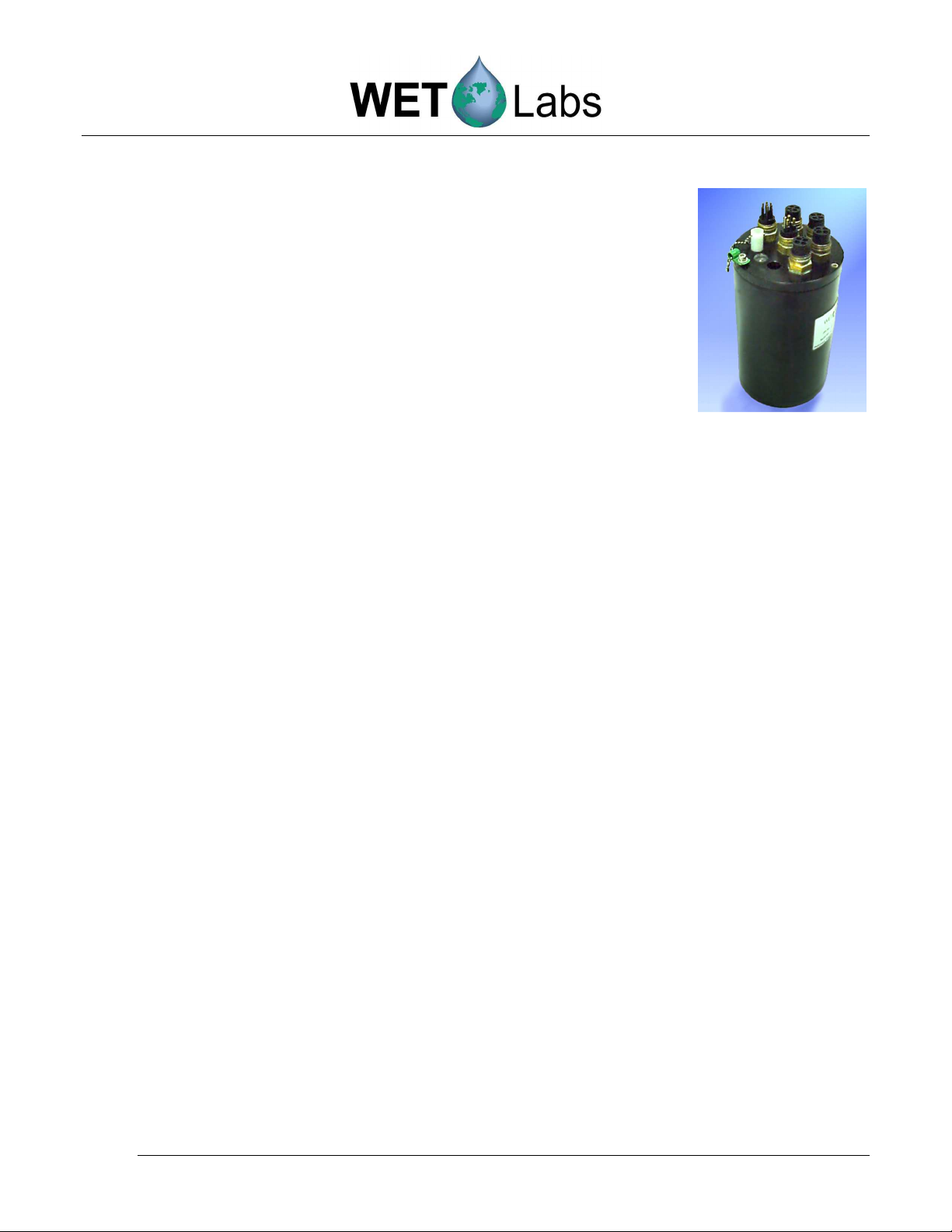
The Data Handler (DH-4) and its associated software,
WET Labs Host, controls four, six or eight input-output
ports for a variety of serial or analog instruments,
providing for the simultaneous collection, time stamping,
storage and merging of data streams from all of the ports.
Depending on the capabilities of the host computer, output
from one to all of the instruments can be viewed in real
time through the host software.
The DH-4 (data logger) is delivered with the following components:
• Test cable
• Dummy plugs with lock collar for each bulkhead connector
• This user’s guide
• Custom Configuration Sheet
• WET Labs Host software on CD
• WET Labs File Archive Processing (WAP) software on CD
• WAP User’s Guide
1.1 Install Host Program
Insert the WET Labs Host software CD into the host computer and copy the contents to a
desired location on the host computer. The WAP software may also be installed at this time.
Refer to the WAP User’s Guide for details on using this data processing software.
1.2 Verify Electrical Functionality
We recommend following the steps below to verify the system’s electrical functionality
when you first receive your DH-4. You will need the following items:
• A clean, solid lab table or work bench.
• A multimeter.
• The DH-4.
• Test cable (includes terminations for an RS-232 connection into a host computer,
power leads that connect to a power supply, and a connector to the DH-4).
• Any meter(s) that will be used with the DH-4.
• A 12–15 volt power supply.
• A computer with WL Host installed.
1.2.1 Check Test Cable Voltage:
1. Connect the power leads to a 12–15 volt power supply (safe operating range).
The black lead is the V+ lead. Use a multimeter to check the input power
before connecting the cable to the instrument.
DH-4 Revision E5 19 June 2006 1
Page 10

•
2. With the power supply turned on, touch the multimeter ground probe to socket 1
on the test cable connector. Connect the “hot” probe to pin 4 (the pin directly
opposite from pin 1). You should measure 12–15 volts across these two pins.
3. Turn the power supply off.
1.3 Verify System Operation
1. If necessary, attach the test cable power leads to a stable power source that supplies
12–15 VDC. Make sure the polarity is correct before switching on the power supply.
2. Connect the RS-232 connector to the desired serial port of the host PC.
Note that if your instrument is sending data in the RS-485 format, an RS-485 to RS232 converter is required to allow proper operation.
WARNING!
Power input on this unit is diode-protected from reverse polarity power-up, but this is not
100 percent insurance against damaging the meter, nor will it protect it from over-voltage.
3. Plug the submerged (wet) end of the test cable into the DH-4.
Applying electrical grade silicone spray or an equivalent to the rubber base of the
instrument bulkhead connector makes the plug insertion easier and provides greater
assurance of a good seal. Do NOT use stopcock greases or products like WD-40.
These will cause de-lamination of the rubber from the metal surface of the bulkhead
connector. Use a connector lock ring if one is available.
Tips
Refer to the Custom Configuration Sheet that ships with your DH-4 for a
summary of factory configuration settings.
•
The Configuration Sheet in Appendix A refers to the example setup used in
this manual.
4. Ensure the DH-4 is connected to the host computer and power supply as above.
5. Connect any additional meter(s) to the DH-4. It may help to refer to the Custom
Configuration Sheet that ships with each DH-4: when possible, configurations
settings specific to your system are set at the factory and documented on the Custom
Configuration Sheet.
6. Start WET Labs Host program.
7. Turn on power to the DH-4.
2 DH-4 Revision E5 19 June 2006
Page 11

8. The first time WET Labs host is started, the
program screen will be mostly empty, with only a
Configure Host Port window appearing.
9. Input the COM port and the baud rate (default 9600). The red backgrounds will turn
white. Close the window. Both time indicators on the left of the window (Host
Status and Logger Status) will increment, indicating the DH-4 and PC are
communicating.
10. Go to the Modes pull-down menu and select Profile Logging.
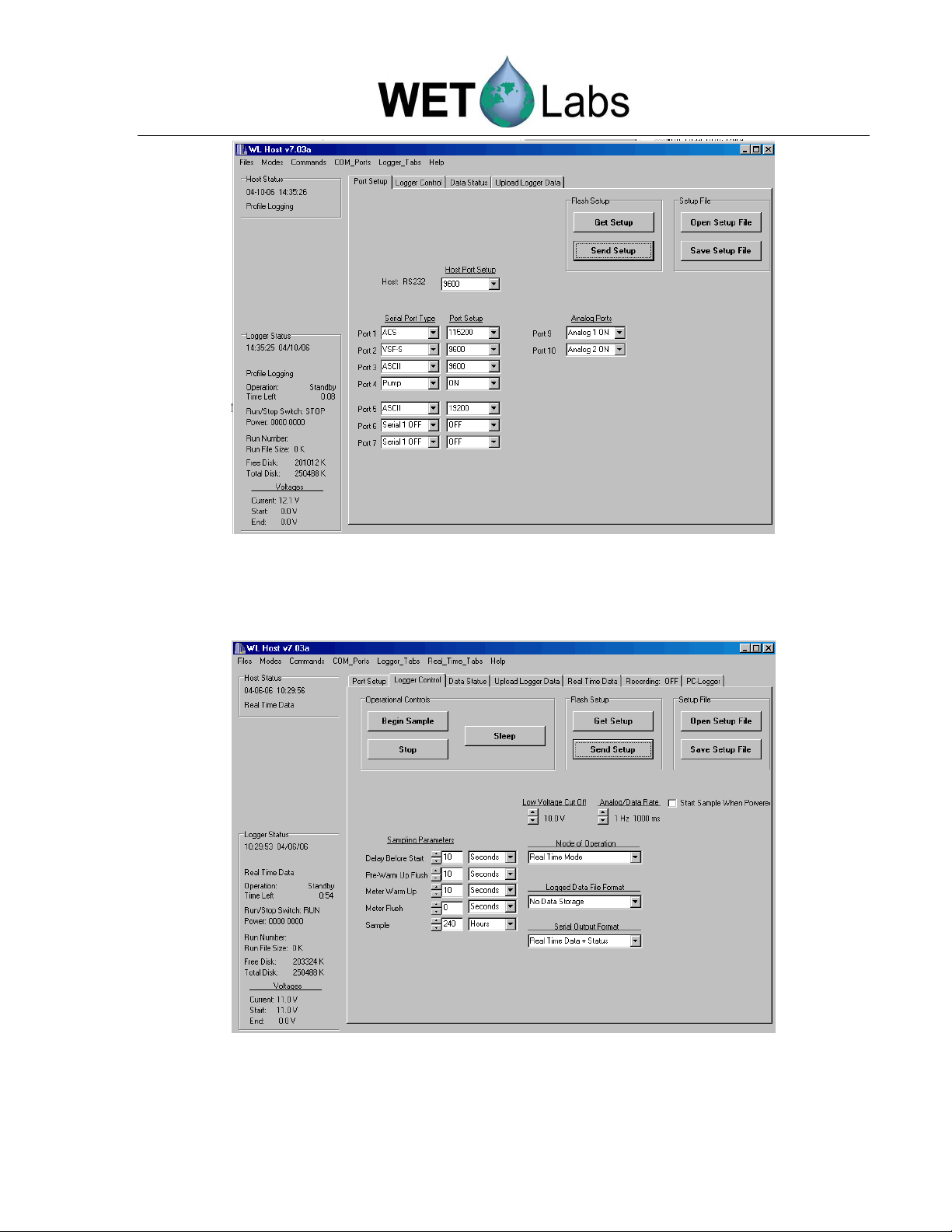
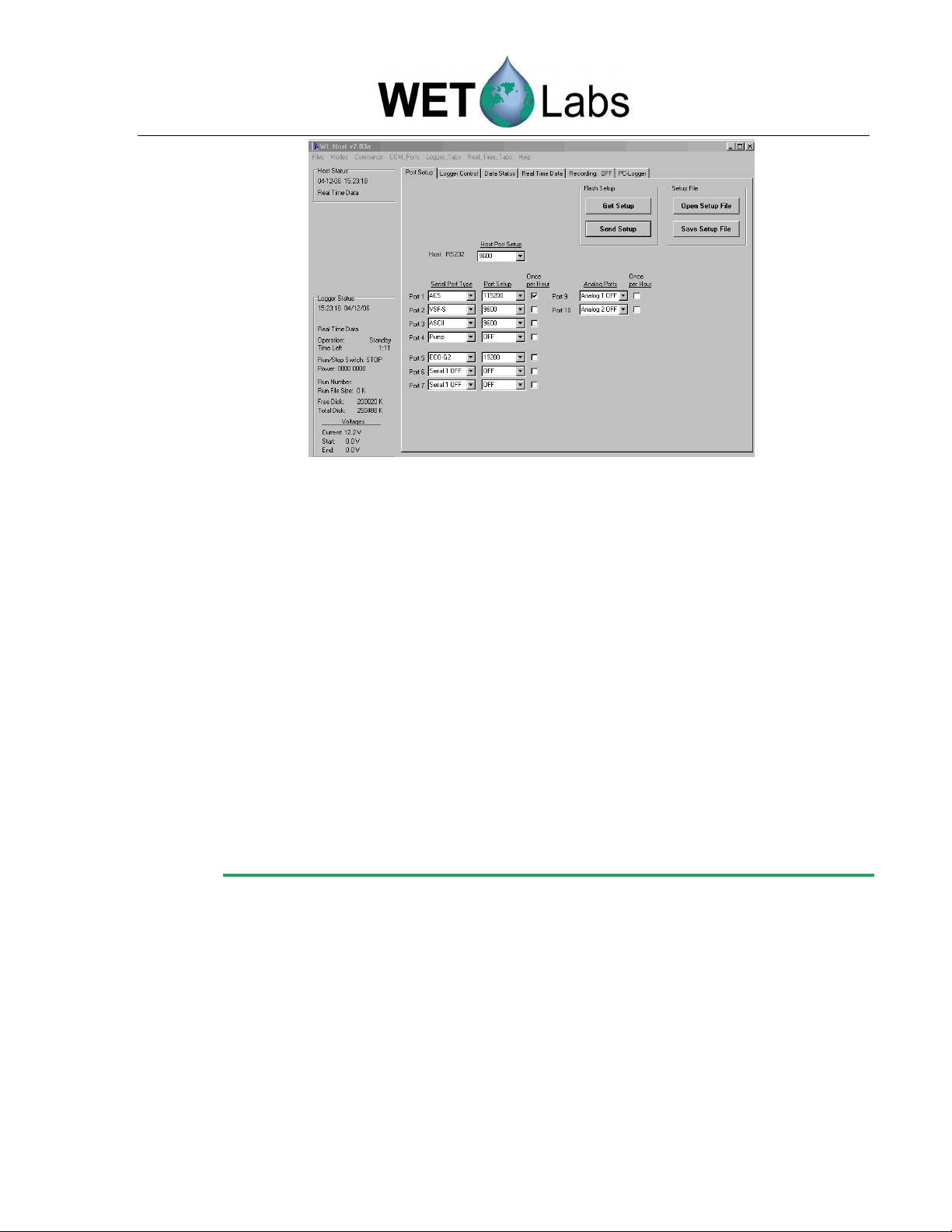
11. Go to the now-visible
Port Setup
tab and press
Get Setup
to load the logger’s settings
into the Host program.
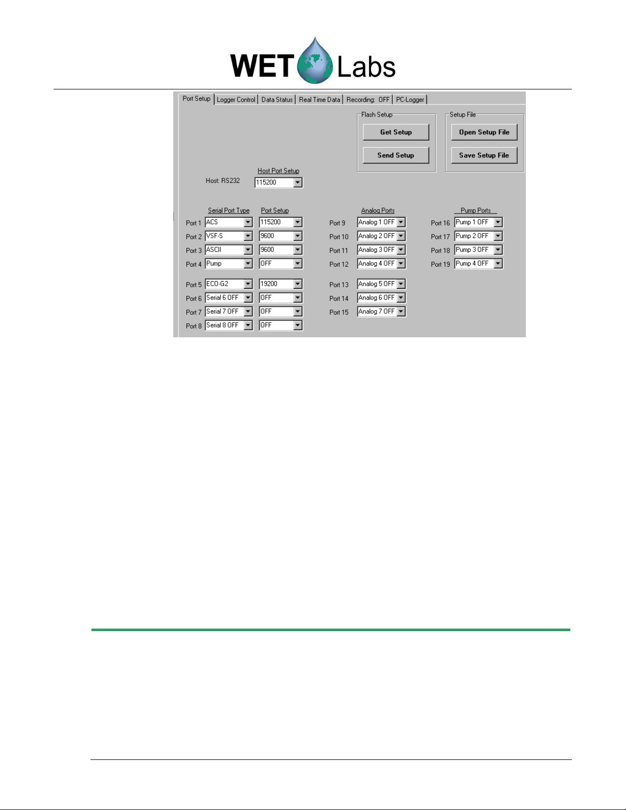
12. Review the Serial Port Type, associated Port Setup baud rate, Analog Ports, and
Pump Ports settings. These settings can also be found on the Custom Configuration
Sheet that ships with your data logger. See Reference section 5.1 for details about
Port Setup options.
Note
For purposes of illustration in this user’s guide, WET Labs Host software runs the following:
Host Port: DH-4
Port 1: ac-s
Port 2: ECO VSFS, Volume Scattering Function Meter with Bio-wiper™
Port 3: CTD
Port 4: Pump
Port 5: ECO FLNTUS, fluorometer-turbidity sensor with Bio-wiper™
DH-4 Revision E5 19 June 2006 3
Page 12
Port Setup tab settings
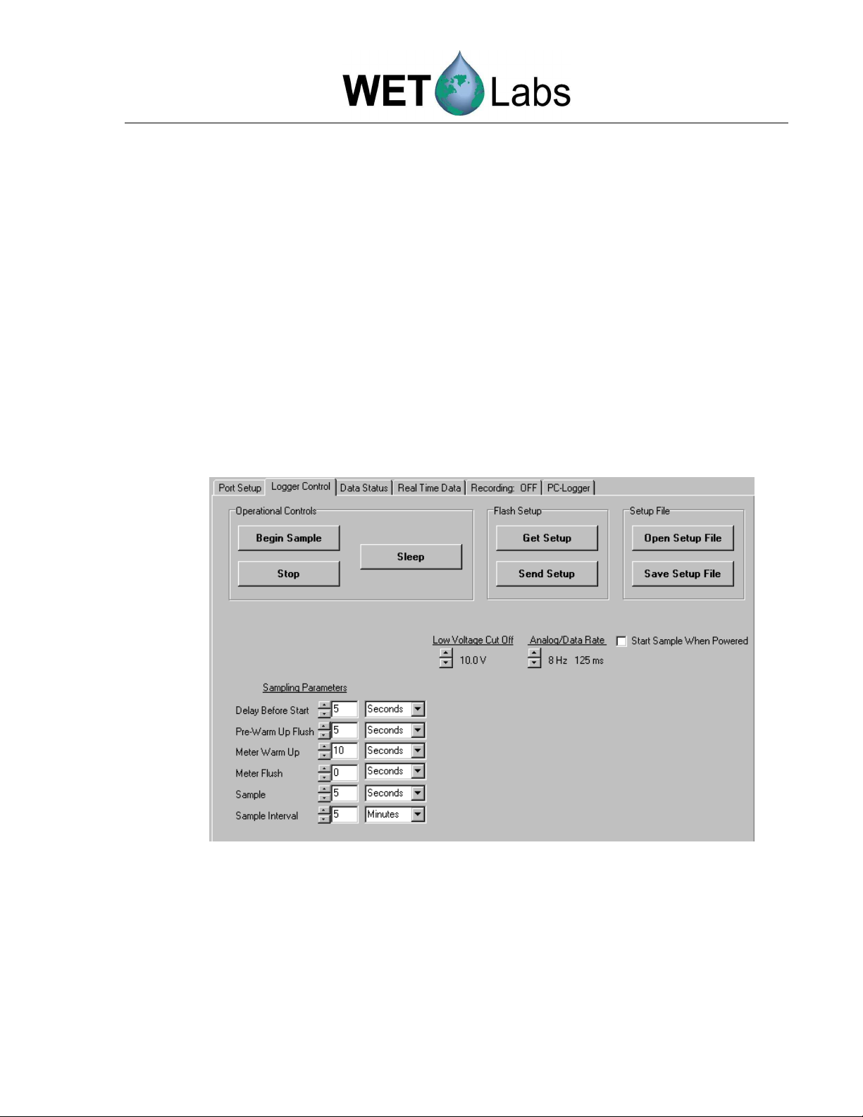
13. Select the Logger
Setup
tab to view the factory-set logger control settings. Refer
to section 5.2 for details on Logger Control configuration options.
Logger Control tab settings
14. To save these settings on the host computer: Select the Save Setup Files button
and in the resulting window, name the setup and click OK. This will allow you to
retrieve the factory settings in the future.
4 DH-4 Revision E5 19 June 2006
Page 13
•
15. There are two options to verify that the meters connected to DH-4 are functional
and communicating. Option 1 allows checking multiple meters. Option 2 tests
one meter at a time, but also provides baud rate information.
Option 1: test multiple meters
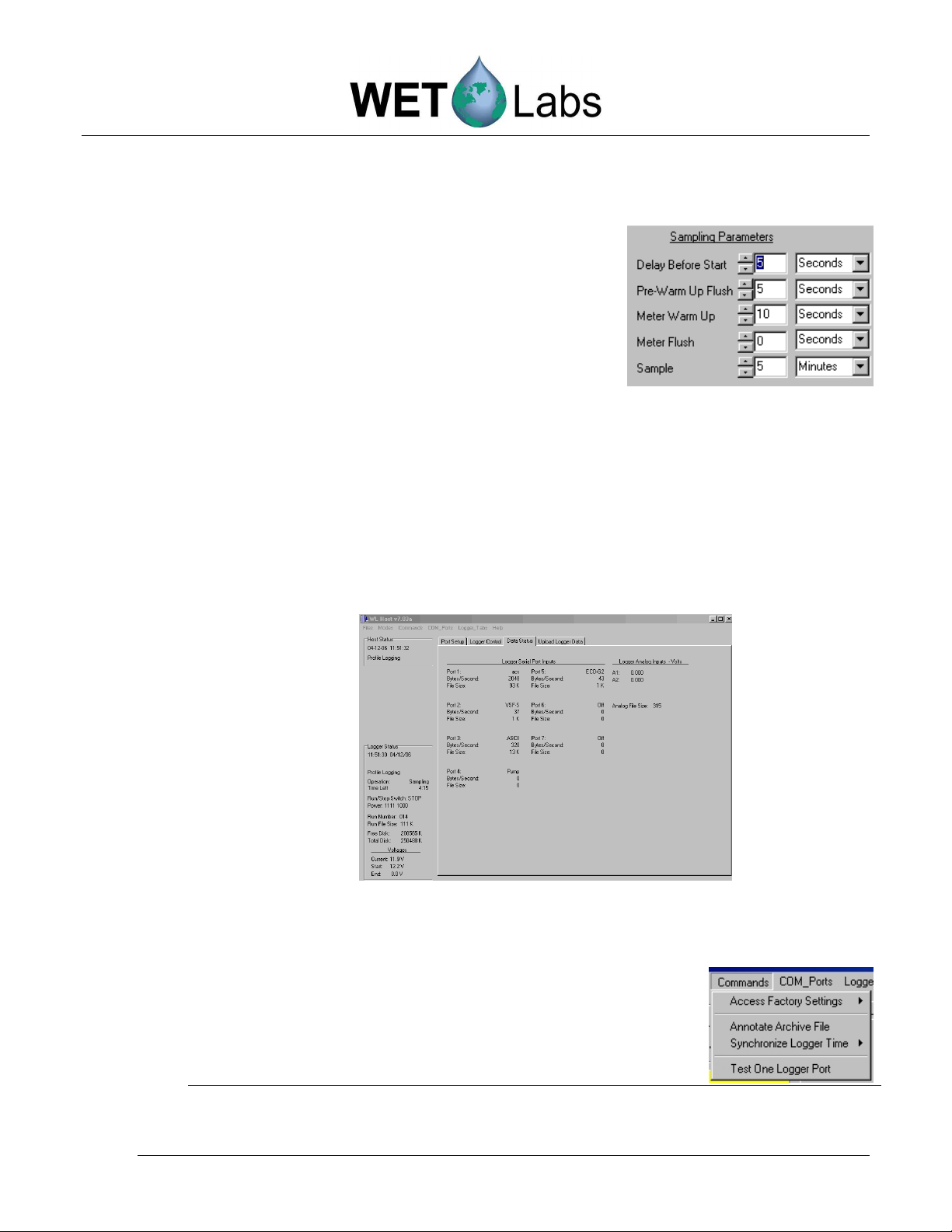
In the Logger Control tab select Begin
Sample. Sampling begins with the program
cycling through the preset sampling
parameters. For example, there will be 5
seconds for Delay Before Start and Pre-
Warm Up Flush, and 10 for Meter WarmUp before the system begins active sampling
for 5 minutes.
Select the Data Status tab. The status of each port is displayed. Depending on
the operation the data logger is performing, either the Bytes/Second and/or the
File Size will increment. While the logger is performing a pre-sampling warmup or flush operation, only the bytes/second will increase. When sampling
begins, the file size will increment as well.
Return to the Logger Control tab and select Stop.
• Option 2: test a single meter
Select Commands/Test One Logger Port
DH-4 Revision E5 19 June 2006 5
Page 14
a. Select the data port (and thus instrument) you
wish to test.
b. Select the instrument’s baud rate.
c. Select the host computer’s baud rate.
d. Select Start Test. The Real_Time Data window
appears, showing scrolling data.
e. Select Stop Test when communication is
verified.
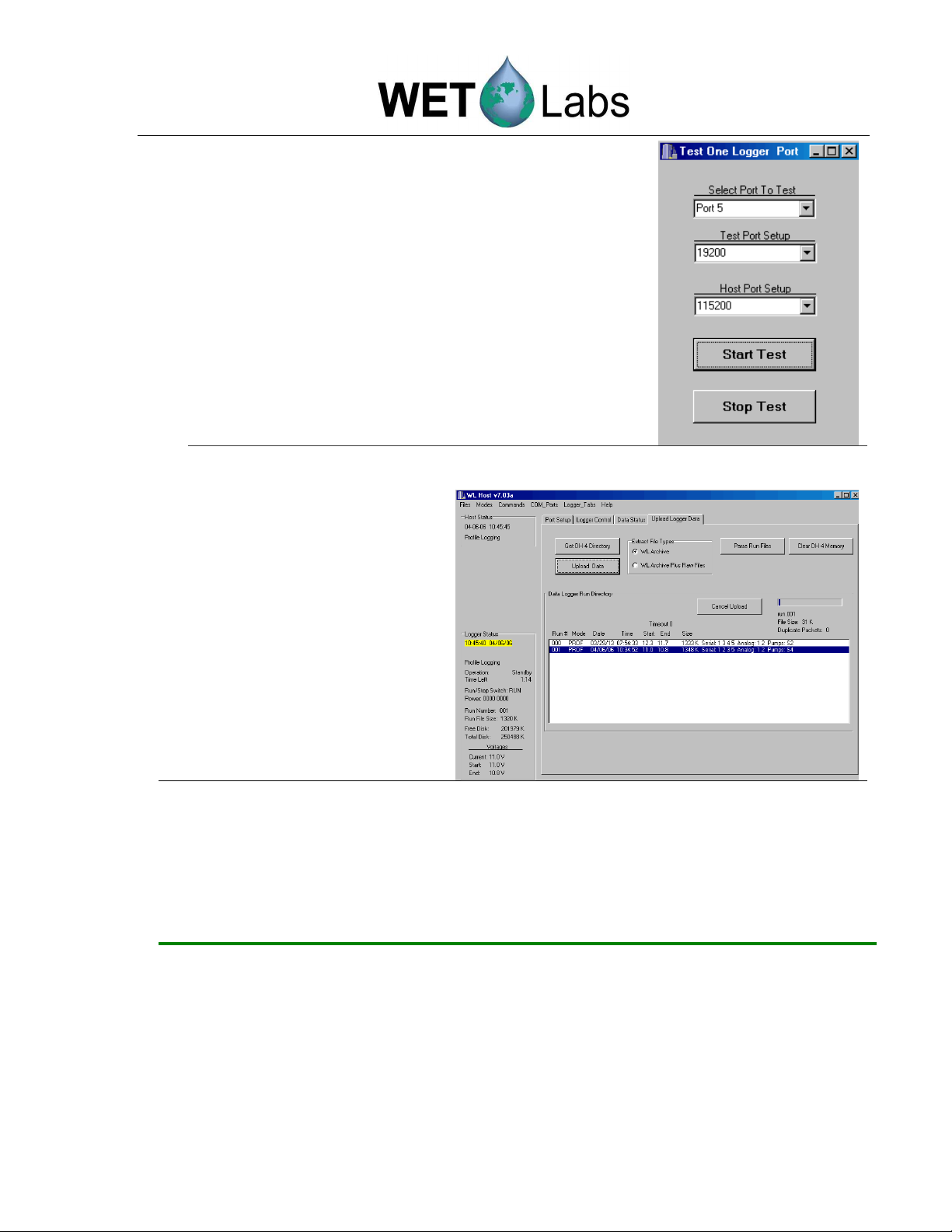
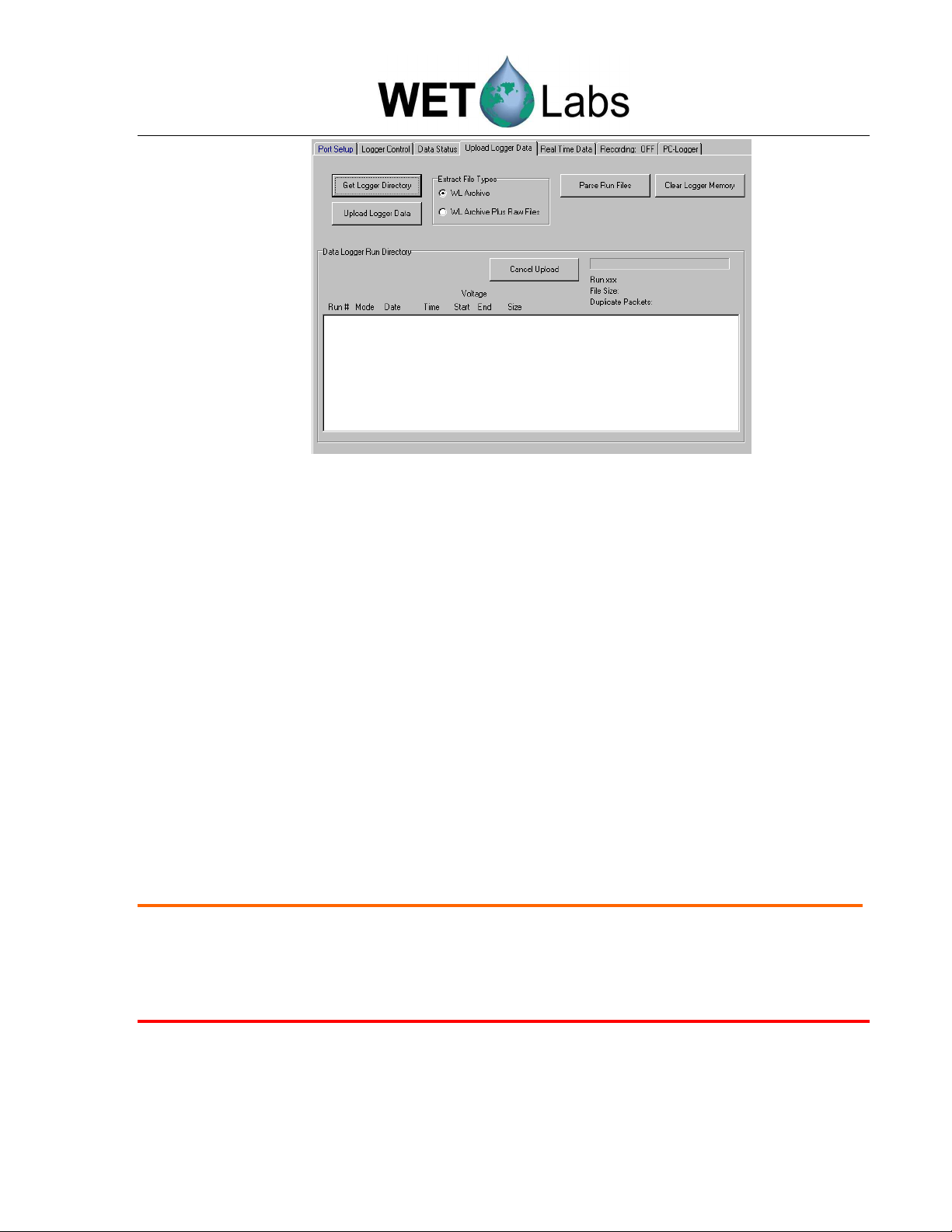
16. To upload and save the test
run from above, select the
Upload Logger Data tab,
then Get DH-4 Directory.
Select a Run # to upload,
then select Upload Logger
Data. Choose a location to
store the data. The upload
status bar indicates file size
and status of upload progress.
17. Select Clear DH-4 Memory to erase the data from the DH-4.
18. Exit the program by selecting Exit under the File menu.
Tip:
6 DH-4 Revision E5 19 June 2006
We highly recommend you experiment with changing and retrieving settings to get
a feel for the flexibility of the host software before deploying your system.
Page 15

2. Setting Operational Modes
WET Labs Host can operate in several modes. Which you choose, of course, depends on
your application. This section describes setup for the three most frequently used modes of
operation:
1. Profile Logging Mode—typically used to assess a column of water, with the logger and
other instruments moving vertically through the column.
2. Moored Logging Mode—typically used for stationary deployments. WET Labs host
provides settings options for low power, or “sleep” intervals, as well as flushing options.
Data is stored at the logger.
3. Real Time Output—similar to profiling, but no data is stored to the logger; it is sent
directly to a host PC. Selecting the appropriate settings to save data in WET Labs Host
are critical in this mode.
Less frequently used, and requiring an advanced understanding of WET Labs Host software:
• Analog Output—Transmits ASCII data from analog meters in real time.
• Advanced Logging/Output—Used only for custom instrument configurations, or
when a combination of modes is required.
DH-4 Revision E5 19 June 2006 7
Page 16

2.1 Profiling Mode
This subsection details the steps and selections to execute a profile for the example system
listed below:
•
Host Port: DH-4
•
Port 1: ac-s
•
Port 2: ECO VSFS, Volume Scattering Function Meter with Bio-wiper™
•
Port 3: CTD
•
Port 4: Pump
•
Port 5: ECO FLNTUS, fluorometer-turbidity sensor with Bio-wiper™
When possible, configuration settings specific to your system are set at the factory. The
Custom Configuration Sheet that ships with your DH-4 represents a hard-copy summary of
the DH-4’s flash settings as they appear in the host program’s setup windows.
2.1.1 Changing or Verifying Configuration Settings
Supply power to the DH-4. Start the host program. Select COM port and baud rate
(default: 9600). Select Profile Logging from the Modes menu.
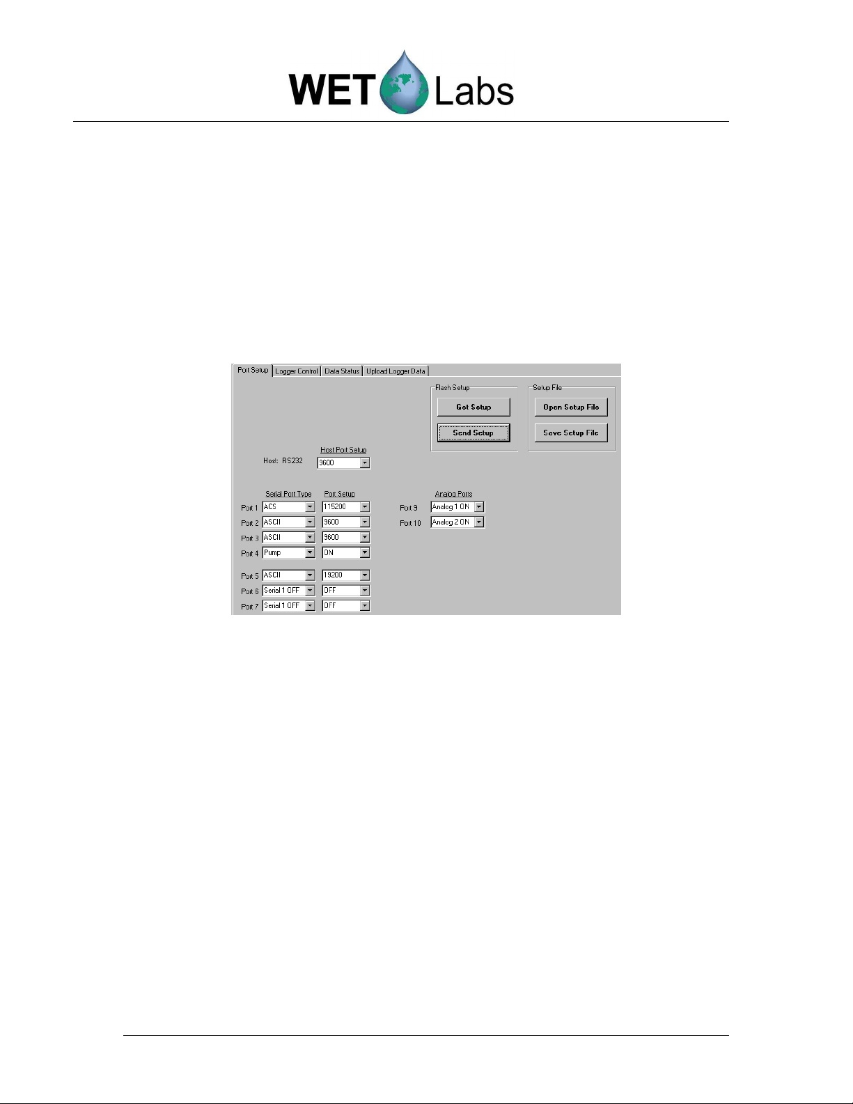
Port Setup tab:
1. Load configuration settings using one of the options below:
• To retrieve the DH-4’s current configuration, select Get Setup.
• To load configuration settings saved to the host PC, select Open Setup
File, select the desired file, then select Send Setup to send those settings
to the DH-4.
• To load factory default settings, go to the Commands pull-down menu, then
Access Factory Settings > Load Default Flash Setup. These are also
available on the Custom Configuration Sheet that ships with your DH-4.
2. If necessary, change the settings under the Serial Port Type, Port Setup,
and Analog Port options. Note that Setup Not Current will appear on a
yellow banner on the status portion of the host program window if any
settings are changed.
8 DH-4 Revision E5 19 June 2006
Page 17
Tip
Sample Port Setup tab settings for profiling mode
Logger Control tab:
1. Check the Low Voltage Cut Off setting. Set to the highest value of the
minimum voltage requirement for all the meters being used. For example, if
you’re deploying an ac-9 (min. requirement 10.0 V), and an ECO fluorometer
(min. requirement 7.5 V), set the Low Voltage Cut Off to 10.0 V.
2. Check Analog/Data Rate setting. Set to the fastest meter’s data rate. For
example, if you’re deploying an ac-s (8 Hz), ac-9 (6 Hz), and an ECO
fluorometer (1 Hz), set the Sample Rate to 8 Hz.
If the logger is being used with meters whose total output is more than 1024 bytes of
data per sample, set the Analog/Data Rate higher than the meter data rate to prevent
data loss. For example, if the total output is 2500 bytes/second, set the logger to at
least 3 Hz.
Set the rate of data acquisition to the fastest
meter’s data rate.
ac-s meters:
ac-9 meters:
ECO meters:
Analog meters:
4 or 8 Hz
6 Hz
1 Hz
1 Hz
DH-4 Revision E5 19 June 2006 9
Page 18
If your system uses analog meters:
Each analog bulkhead on the DH-4 can optionally support two analog channels.
Therefore, each analog bulkhead has two analog definitions in the DH-4 host
program. (Analog 1 and Analog 2 correlate with analog bulkhead 1, Analog 3 and
Analog 4 correlates to analog bulkhead 2, etc.)
To use both channels on a given bulkhead, there must be a Y cable that originates
from the DH-4 bulkhead and terminates at each of the supported instruments. If a
Y cable is not available, each analog port will only support one analog device at
the odd numbered Analog ID (Analog Bulkhead 1 = Analog 1, Analog Bulkhead
2 = Analog 3, etc.)
3. When the desired settings are input: Select Send Setup to send the configuration
settings to the DH-4’s flash memory. To save the configuration settings to the host
computer, select Save Setup File.
4. To begin sampling, select the Begin Sample button.
Sample Logger Control tab settings for profiling mode
10 DH-4 Revision E5 19 June 2006
Page 19

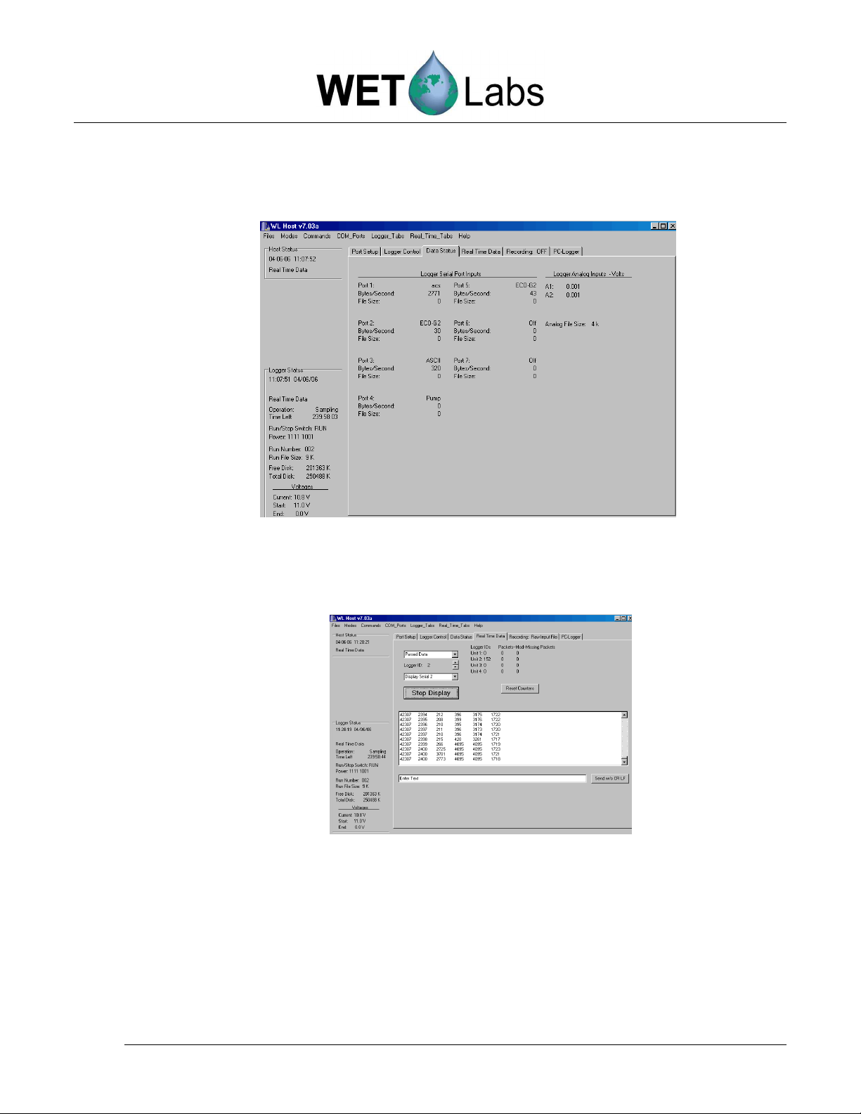
2.1.2 Tracking Incoming Data
Select the Data Status tab to display the current data status of all meters. Refer to
Reference section 5.3 for details of what each status line represents.
Viewing Data Status tab, profiling mode
To stop the sample, press Stop at the Logger Control tab.
2.1.3 Uploading Data
1. Go to the Port Setup tab and press Get Setup to ensure the most recent flash
settings are loaded.
2. Under the Logger Port Setup combo box, choose the fastest data rate that the host
cable and COM port can support. Three-meter cables can run at 115,200 baud.
3. Press Send Setup to send the baud rate change to the data logger. The logger will
change to the meter’s baud rate and the host program will follow suit. There will be a
brief pause as the logger and PC change their baud rates.
Occasionally, the logger and PC will lose track of each other while the baud rate
change is occurring. This will be indicated by a red background for baud rate. Press
Send Setup again. It may be necessary to toggle power to the data logger if resending the command doesn’t synchronize baud rates.
DH-4 Revision E5 19 June 2006 11
Page 20
Upload Logger Data in profiling mode
4. At the Upload Logger Data tab, select Get DH-4 Directory to retrieve all the DH-4
file information.
5. Select one or more of the runs that appear in the Data Logger Run Directory. In the
example above run 001 will be uploaded.
6. Select WL Archive from the combo box. This will create a data file that combines the
data from the selected files.
7. Select the runs to be uploaded, then select Upload Data to upload them. The status
section will update while uploading is occurring.
8. Selecting Cancel Upload will stop data upload. If multiple runs have been selected,
you will be prompted to cancel all uploads or individual run uploads.
2.1.4 Clearing DH-4 Memory
Caution!
Once “Clear DH-4 Memory” is pressed, the data is not retrievable.
WARNING!
Turning off the data logger while memory clearing is in progress
corrupted data logger file system.
To clear the DH-4 memory, select the Clear DH-4 Memory button in the Upload
Logger Data tab (above).
12 DH-4 Revision E5 19 June 2006
WILL
result in a
Page 21

2.2 Moored Mode
This subsection details the steps and selections to execute a moored operation for the
example system listed below:
• Host Port: DH-4
• Port 1: ac-s
• Port 2: ECO VSFS, Volume Scattering Function Meter with Bio-wiper™
• Port 3: CTD
• Port 4: Pump
• Port 5: ECO FLNTUS, fluorometer-turbidity sensor with Bio-wiper™
When possible, configuration settings specific to your system are set at the factory. The
Custom Configuration Sheet that ships with your DH-4 represents a hard-copy summary of
the DH-4’s flash settings as they appear in the host program setup windows.
2.2.1 Moored Logging Configuration Settings
Supply power to the DH-4; start the WET Labs Host program. Select COM port and baud
rate (default: 9600). Select Moored Logging from the Modes menu.
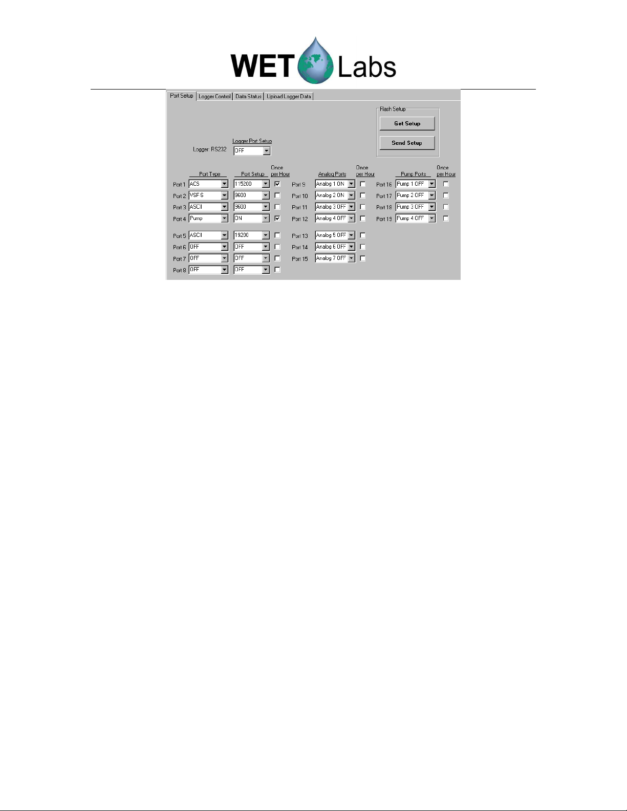
Port Setup tab:
1. Load configuration settings using one of the options below:
• To retrieve the DH-4’s current configuration, select Get Setup.
• To load configuration settings saved to the host PC, select Open Setup
File, select the desired file, then select Send Setup to send those settings
to the DH-4.
• To load factory default settings, go to the Commands pull-down menu,
then Access Factory Settings > Load Default Flash Setup. Note that
these are also available on the Custom Configuration Sheet that ships with
your DH-4.
2. If necessary, change the settings under the Serial Port Type, Port Setup, Analog
Port options. Note that Setup Not Current will appear on a yellow banner on the
status portion of the host program window if any settings are changed.
3. Check the Once Per Hour checkbox to allow instruments with a high current
draw to run only during the first sample period after the beginning (“top”) of
the hour. This allows you to obtain several samples per hour from instruments
with lower current draws without the power penalty of instruments with a high
current draw.
DH-4 Revision E5 19 June 2006 13
Page 22
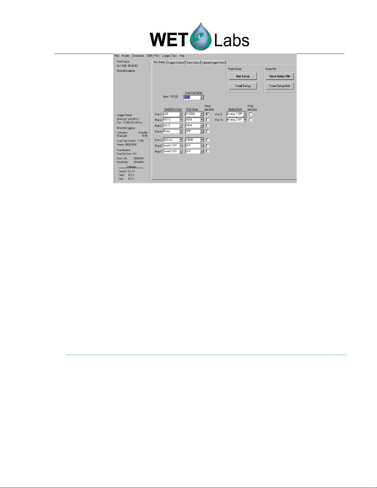
Sample Port Setup settings for moored mode
Logger Control tab:
1. Check the Low Voltage Cut Off setting. Set to the highest value of the
minimum voltage requirement for all the meters being used. For example, if
you’re deploying an ac-9 (min. requirement 10.0 V), and an ECO fluorometer
(min. requirement 7.5 V), set the Low Voltage Cut Off to 10.0 V.
2. Check Analog/Data Rate setting. Set to the fastest meter’s data rate. For
example, if you’re deploying an ac-s (4 or 8 Hz), ac-9 (6 Hz), and an ECO
fluorometer (1 Hz), set the Sample Rate to 8 Hz.
If the logger is being used with meters whose total output is more than 1024
bytes of data per sample, set the Analog/Data Rate higher than the meter data
rate to prevent data loss. For example, if the total output is 2500 bytes/second,
set the logger to at least 3 Hz.
Tip
Set the rate of data acquisition to the fastest
meter’s data rate.
ac-s meters:
ac-9 meters:
ECO meters:
Analog meters:
If your system uses analog meters:
Each analog bulkhead on the DH-4 can optionally support two analog channels.
Therefore, each analog bulkhead has two analog definitions in the DH-4 host
program. (Analog 1 and Analog 2 correlate with analog bulkhead 1, Analog 3 and
Analog 4 correlates to analog bulkhead 2, etc.)
To use both channels on a given bulkhead, there must be a Y cable that originates
from the DH-4 bulkhead and terminates at each of the supported instruments. If a
Y cable is not available, each analog port will only support one analog device at
the odd numbered Analog ID (Analog Bulkhead 1 = Analog 1, Analog Bulkhead
2 = Analog 3, etc.)
4 or 8 Hz
6 Hz
1 Hz
1 Hz
14 DH-4 Revision E5 19 June 2006
Page 23

3. Commands drop down menu:
Synchronize the DH-4 and
host PC clocks. Select
Synchronize Logger Time
then
Synchronize Time Now
,
.
Note
Turning on “Automatic Time Sync” will prevent you from seeing the DH-4 clock drift and should
not be used for moored applications.
4. When the desired settings are input: Select Send Setup to send the configuration
settings to the DH-4’s flash memory. To save the configuration settings to the host
computer, select Save Setup File.
5. To begin sampling, select the Begin Sample button.
Sample Logger Control settings for moored mode
DH-4 Revision E5 19 June 2006 15
Page 24

2.2.2 Tracking Incoming Data
Select the Data Status tab to display the current data status of all meters. See Reference
section 5.3 for details of what each status line represents.
Viewing Data Status tab in moored mode
To stop the sample, press Stop at the Logger Control tab.
2.2.3 Uploading Data
1. Go to the Port Setup tab and press Get Setup to ensure the most recent flash
settings have been loaded from the data logger.
2. Under the Logger Port Setup combo box, choose the fastest data rate that the host
cable and COM port can support. Three-meter cables can run at 115,200 baud.
3. Press Send Setup to send the baud rate change to the data logger. The logger will
change to the meter’s baud rate and the host program will follow suit. There will brief
pause as the logger and PC change their baud rates.
Occasionally, the logger and PC will lose track of each other while the baud rate
change is occurring. This will be indicated by a red background for baud rate. Press
Send Setup again. It may be necessary to toggle power to the data logger if re-sending
the command doesn’t synchronize baud rates.
4. At the Upload Logger Data tab press Get DH-4 Directory to retrieve all the DH-4
file information.
5. Select one or more of the runs that appear in the Data Logger Run Directory. In the
example below, runs 002 and 003 will be uploaded.
6. Select WL Archive from the combo box. This will create a data file that combines the
data from the selected files.
16 DH-4 Revision E5 19 June 2006
Page 25

7. Select the runs to be uploaded, then select Upload Data to upload them. The status
section will update while uploading is occurring.
8. Selecting Cancel Upload will stop data upload. If multiple runs have been selected,
you will be prompted to cancel all uploads or individual run uploads.
Sample Upload Data in moored mode
2.2.4 Clearing DH-4 Memory
Caution!
Once “Clear DH-4 Memory” is pressed, the data is not retrievable.
WARNING!
Turning off the DH-4 while memory clearing is in progress
WILL
To clear the DH-4 memory, select the Clear DH-4 Memory button in the Upload
Logger Data tab (above).
corrupt its file system.
DH-4 Revision E5 19 June 2006 17
Page 26

18 DH-4 Revision E5 19 June 2006
Page 27

2.3 Real-time Mode
Because data is not saved by either an individual instrument or the DH-4 in this mode, it is
critical to set up WET Labs Host software so that all data is sent to the host PC.
This subsection details the steps and selections to execute a real-time operation for the
example system listed below:
• Host Port: DH-4
• Port 1: ac-s
• Port 2: ECO VSFS, Volume Scattering Function Meter with Bio-wiper™
• Port 3: CTD
• Port 4: Pump
• Port 5: ECO FLNTUS, fluorometer-turbidity sensor with Bio-wiper™
When possible, configuration settings specific to your system are set at the factory. The
Custom Configuration Sheet that ships with your DH-4 represents a hard-copy summary of
the DH-4’s flash settings as they appear in the host program setup windows.
2.3.1 Setting Configurations
1. Supply power to the DH-4; start the WET Labs Host program.
2. Select COM port and baud rate (default is 9600).
3. Select Real Time Data from the Modes menu.
Port Setup tab:
1. Load configuration settings using one of the options below:
• To retrieve the DH-4’s current configuration, select Get Setup.
• To load configuration settings saved to the host PC, select Open Setup
File, select the desired file, then select Send Setup to send those settings
to the DH-4.
• To load factory default settings, go to the Commands pull-down menu,
then Access Factory Settings > Load Default Flash Setup. Note that
these are also available on the Custom Configuration Sheet that ships with
your DH-4.
2. Select Host Port Setup baud rate. Though the default is 9600, data in this mode is
coming through the DH-4 directly to the PC from each instrument. A much faster
data rate, such as 115200, is recommended to prevent a bottleneck or error messages.
3. If necessary, change the settings under the Serial Port Type, Port Setup, and
Analog Port options. Note that Setup Not Current will appear on a yellow banner
on the status portion of the host program window if any settings are changed.
DH-4 Revision E5 19 June 2006 19
Page 28
Port Setup for Real Time mode
Logger Control tab:
1. Check the Low Voltage Cut Off setting. Set to the highest value of the minimum
voltage requirement for all the meters being used. For example, if you’re deploying an
ac-9 (min. requirement 10.0 V), and an ECO fluorometer (min. requirement 7.5 V), set
the Low Voltage Cut Off to 10.0 V.
2. Check Analog/Data Rate setting. Set to the fastest meter’s data rate. For example, if
you’re deploying an ac-s (8 Hz), ac-9 (6 Hz), and an ECO fluorometer (1 Hz), set the
Sample Rate to 8 Hz.
If the logger is being used with meters whose total output is more than 1024 bytes of
data per sample, set the Analog/Data Rate higher than the meter data rate to prevent
data loss. For example, if the total output is 2500 bytes/second, set the logger to at
least 3 Hz.
Tip
Set the rate of data acquisition to
the fastest meter’s data rate.
ac-s meters:
ac-9 meters:
ECO meters:
Analog meters:
4 or 8 Hz
6 Hz
1 Hz
1 Hz
If your system uses analog meters:
Each analog bulkhead on the DH-4 can optionally support two analog channels.
Therefore, each analog bulkhead has two analog definitions in the DH-4 host
program. (Analog 1 and Analog 2 correlate with analog bulkhead 1, Analog 3 and
Analog 4 correlates to analog bulkhead 2, etc.)
To use both channels on a given bulkhead, there must be a Y cable that originates
from the DH-4 bulkhead and terminates at each of the supported instruments. If a
Y cable is not available, each analog port will only support one analog device at
the odd numbered Analog ID (Analog Bulkhead 1 = Analog 1, Analog Bulkhead
2 = Analog 3, etc.)
20 DH-4 Revision E5 19 June 2006
Page 29

5. When the desired settings are input: Select Send Setup to send the configuration
settings to the DH-4’s flash memory. To save the configuration settings to the host
computer, select Save Setup File.
Logger Control for Real Time mode
2.3.2 Saving Files in Real-time
1. Select the Recording: OFF/ON tab.
Recording: OFF/ON
2. Check Record Logger Data and Record PC-Logger boxes. All real time data
being received by the PC via the DH-4 will be recorded.
DH-4 Revision E5 19 June 2006 21
Page 30

3. Choose one of the three record buttons and enter a file name and location.
• Record Archive—Records an archive file until the Stop button is
pressed. To make the file name compatible with the file extraction
program WAP, use a single word file name without any spaces and a 3
digit file extension where the extension runs from 000-999.
This option is recommended for recording data while profiling.
Example:
CruiseOne.001 is acceptable.
CruiseOne.dat is not recommended.
Cruise One.001 is not acceptable.
• 1 Hour Archive Files—Creates a new archive file at the start of each
hour appending a 2 digit year, Julian date, and hour on the end of the file
name. To make the file name compatible with the file extraction program
WAP, use a single file name without any extensions. This option is
recommended for recording data during towed or flow-through operations.
Example: If the user enters the file name CruiseOne at 7:05 pm on
January 17, 2004, the host will create a file named CruiseOne04_17.019.
If the Host is still recording at 8:00 pm, the Host will close the existing file
and create a new file named CruiseOne04_17.020.
• 1 Day Archive Files—Creates a new archive file at the start of each new
day appending a 2 digit year and Julian date to the end of the file name.
This option is recommended for recording data during moored operations.
Example: If the user enters the file name CruiseOne on January 17, 2004,
the Host will create a file named CruiseOne04.017.
4. To begin sampling, select the Begin Sample button at the Logger
Control tab.
22 DH-4 Revision E5 19 June 2006
Page 31
2.3.3 Viewing Data
Select the Data Status tab to display the current status of all serial and analog meters.
Refer to section 5.3 for details of what each status line represents.
Sample Data Status for real-time mode
Incoming data can also be viewed in the Real Time Data tab, though with the exception
of ASCII data, it will appear as gibberish until extracted.
Real Time Data tab (incoming ASCII ECO data shown).
To stop the sample, press Stop at the Recording: OFF/ON tab. The data file will be
saved to the chosen location on the host PC.
DH-4 Revision E5 19 June 2006 23
Page 32

24 DH-4 Revision E5 19 June 2006
Page 33

3. Reference: Status Displays
This section describes the functions of the various buttons, selectable options, and status
indicators of the WET Labs Host Program and is designed to be used primarily as a reference
section. Functionally, the program is divided into tabs for logger setup and data collection, with
additional options available from the pull-down menus at the top of the screen. Note that
depending on the operational mode you’ve chosen, not all tabs will be visible.
The Setup Status banner in the upper left hand corner of the host program indicates whether the
parameters on the Port Setup and Logger Control tabs contain the same values that the logger
is currently using.
3.1 Setup Status
If a yellow Setup is Not Current banner is visible, the host may
not contain the same settings that the logger does. To get the
current logger settings, press the Get Setup button on either the
Port Setup or Logger Control tabs.
If the yellow status banner is not visible, the host and the logger have matching parameters
for the Port Setup and Logger Control settings.
3.2 Host Status
•
Time and Date: Displays the time and date of the host PC
and the data logger. The host program automatically updates
the time if the data logger is in standby mode and Automatic
Time Sync is turned on.
•
Mode: Displays the operating mode of the host: Moored
Logging, Profile Logging, Real Time Output, Analog
Output, Advanced Logging/Output.
•
Communication: Displays the Host COM port being used
and the baud rate. Note that if the COM has a red
background, the Logger is not communicating with the host.
If the baud rate background is red, it is incorrect.
3.3 Logger Port Setup
•
COM port selector: Determines from
which COM port the host computer
can communicate with the Logger.
•
Baud rate selector: Determines at
which baud rate the host and logger
communicate.
DH-4 Revision E5 19 June 2006 25
Page 34

3.4 Logger Status
•
Time and date coming from the DH-4. Can be synchronized
with the host PC.
• Operational mode indicator. Matches the Host Status
operation indicator as long as setup is current.
•
Operation:
Shows the operation the DH-4 is currently
performing:
Stand By—Waiting for a command.
Delay—A delay at the start of a data collection sequence before
the meter warm up.
Pre-flush—System pumps flush meters prior to warm-up. Data is
not stored.
Warm Up—Selected meters are powered to reach a stable
operating temperature. Data is not stored. The auxiliary pump is
not in operation.
Flush—Selected meters are powered, and the auxiliary pump is
powered to flush out the meter passages. Data is not stored.
Sample—The data collection segment of the sample sequence.
All selected meters and pumps will be on. Data will be logged if
logging has been selected. Data will be transmitted if Real Time
Data has been selected.
•
Time Left:
Shows the actual time remaining in each operation described above. During
Standby, this is elapsed time since the standby operation began.
•
Run/Stop Switch:
Optional magnetic actuator switch that controls logic. Note that if
power is applied to the logger it will become fully active regardless of the switch’s
position. Status indicators:
RUN—actuator plug inserted. Logger will begin sampling.
STOP—actuator plug removed. DH-4 will terminate the current sample.
Disabled—DH-4 is ready to receive commands.
•
Power:
debug display.
•
Run File Size:
•
Free Disk:
Indicates which relays 1–8 have been turned on. This is primarily a factory
Indicates the current file size of collected data.
Indicates the amount of flash disk space in Kbytes that is unused. The data
logger can use all but the last 200 Kbytes of this flash disk for data storage.
•
Total Disk:
Indicates the total flash disk size in Kbytes. This shows the used and unused
space. All but the last 200 Kb of the flash disk are available for data storage.
•
Voltage:
Current
Start—
End—
—displays existing voltage and is updated once per second.
displays the voltage at the start of the most recent sample.
displays the voltage when the last sample was ended.
26 DH-4 Revision E5 19 June 2006
Page 35

If the modes under the Host Status and the Logger Status are
not the same, the yellow Setup is Not Current banner will be
visible. Press Send Setup to change the loaded status to the
Host Status. Press Get Setup to retrieve the Logger status.
For example, selecting Send Setup will change logger status
to moored. Selecting Get Setup will change the host to Real
Time.
DH-4 Revision E5 19 June 2006 27
Page 36

28 DH-4 Revision E5 19 June 2006
Page 37

4. Reference: Pull-down Menus
The five pull-down menus in WET Labs Host are shown below.
4.1 Files
Open Host Setup File: Opens a saved WL Host
setup file.
Save Host Setup File: Saves a WL Host program
setup configuration. (Particularly useful for saving
settings for both moored and profiling operation.)
File will be saved in the directory the host program
is installed in.
Exit: Closes the host program, automatically saving
the existing (currently selected) configurations in a
file named last.wlh.
4.2 Modes
Moored Logging: for use with moored applications.
Profile Logging: for use with profiling applications.
Real-time Output: for use when no data will be stored on the
logger, but rather sent directly to a host PC in real time.
Analog Output: use to sample and transmit ASCII data from
a set of analog meters in real time. If any digital/serial meters
are to be used, use Real Time Mode.
Advanced User: Use for deployments where a combination
of moored and profile settings are desired.
PC-Logger: for use when data will be sent to the host PC
instead of the data logger.
4.3 Commands
When Moored or Profile modes are selected, the options at
right are available.
DH-4 Revision E5 19 June 2006 29
Page 38

When Real Time and Advanced User modes are selected,
the options shown at right are available.
When Analog Output mode is selected, the options at right
are available.
4.3.1 Access Factory Settings >
The options under this submenu are primarily used for WET Labs personnel for
troubleshooting or de-bugging and should be disregarded.
•
Reset to Monitor
: Exits the host program and allows the user to access low
level functions.
•
Change Logger ID
: Allows changing the default data logger at port 2 to
another port number.
•
Show Analog Calibration
: View calibration settings for analog
instruments. This window can also be used for troubleshooting with WET
Labs personnel.
•
Show Hardware Configuration
: View hardware configurations for all
instruments.
•
Load Default Flash Setup
: Resets the DH-4 configuration settings to those
shipped from the factory.
•
Write Debug File, Add Pad
: Used by WET Labs personnel for debugging.
4.3.2 Annotate Archive File
This allows you to add notes about a given run. These are
inserted into the archive file as ASCII text in logger ID 1,
Port 9. Enter the text to be stored in the Annotate Here box.
Select Insert Annotation to add user-entered text to the
archive file.
Select Start Water Sample to input the time and date the
water sample started.
Select End Water Sample to input the end time.
Water sample annotations may also be incremented or
decremented by clicking on the up arrows next to Next
Water Sample.
Select Reset Sample Count to return the count to 1.
30 DH-4 Revision E5 19 June 2006
Page 39

Note
4.3.3 Synchronize Logger Time >
Automatic Time Sync will constantly update the
data logger’s time while it’s connected to a host
and not sampling and should be used to keep the
logger and the host PC clocks synchronized.
Synchronize Time Now will synchronize the
data logger to the current host PC time.
Turning on Automatic Time Sync will prevent you from seeing the logger clock drift and
should not be used in Moored Mode.
4.3.4 Test One Logger Port
Allows you to test that a meter is properly connected and
communicating with the host. Serial ports 1–8 or analog ports
may be tested at a user-selected baud rate.
To test a port:
1. Select the data port (and thus instrument) you wish to test.
2. Select the instrument’s baud rate.
3. Select the host computer’s baud rate.
4. Select Start Test. The Real_Time window appears,
showing scrolling data.
5. Select Stop Test when communication is verified.
DH-4 Revision E5 19 June 2006 31
Page 40

4.4 Logger_Port
Show/Hide Logger Port Setup
Displays or minimizes the Logger Port Setup in the status
area of WL Host.
Show Logger Port Statistics
Troubleshooting, debugging screen for factory use.
Auto Baud Rate Detection
If checked, the Host software automatically checks that the
Host PC and DH-4 baud rate match.
32 DH-4 Revision E5 19 June 2006
Page 41

DH-4 Revision E5 19 June 2006 33
Page 42

Page 43

5. Reference: Window Tabs
There are seven tabs associated with all aspects of operating the data logger for various
types of deployments. Note that depending on the operating mode you’ve chosen, not all
tabs will be available.
Visible tabs for each operating mode:
Moored Logging
Profile Logging
Real Time Output
Analog Output
Advanced User
5.1 Port Setup
5.1.1 Logger Port Setup
Selectable baud rate for the host port-to-DH-4 connection. Default is 9600.
DH-4 Revision E5 19 June 2006 35
Page 44

5.1.2 Port Type
Refer to the data logger-specific configuration sheet to identify which bulkhead
connector is associated with each serial port for your specific data logger. Except
where noted, all serial ports are powered during the warm up, flush, and sample
segments of a run. Serial ports may be powered during pre-flush if the port is
selected as a pump.
OFF
—The port will not be powered, nor will any data be accepted from this port
during data sampling.
AC9
—Any data is accepted by this port. The port will be turned off if the voltage
drops below 10.0V. Baud rate: 19200.
AC-S
—Any data is accepted by this port. This port will be turned off if the voltage
drops below 9.5 V. This allows a sample to continue while protecting the ac-s from
damage. Baud rate: 115200.
ASCII
—ASCII data that is terminated with <Carriage Return><Line Feed> (CR
LF) will be accepted by this serial port. Baud rates: 600–115200.
Binary
—All data will be accepted by this serial port. The serial port type has no
restrictions on the format of the data that it receives, making it a good initial
selection when setting up new meters. Baud rates: 600–115200.
ECO-G2
—This port will accept <CRLF>-terminated data and recognizes the
“close shuttered shutdown” command used by the 2nd generation ECO meters.
This allows the meter to close its bio-wiper before the DH-4 removes power
during moored deployments. Baud rate: 19200.
GPS
—Accepts NMEA-0183 data format GPRMC. Baud rate: 4800.
Pump
—This port will provide power for pump operation during the flush and
sample segments of the data collection. If pre-flush is selected, this port will be
powered throughout the sample sequence, including pre-flush and warm-up. No
data will be processed from this port.
Remote Host
—This port provides power and data to telemetry equipment. When
the DH-4 is either in standby or sample mode, the DH-4 will power this port and
transmit data out the port.
SBE 37-SM
—The data logger will query the SBE-37SM every 4 seconds, at
which point the SBE’s data will be retrieved. The SBE 37-SM must be logging
data and be “sleeping” between samples. Baud rate: 9600.
VSF-S
—This type will accept ASCII data from the first generation of ECO
meters such as the VSF and DFL. Additionally, at the end of the sample segment
the ECO-G1 “close shutter” command will be sent to the meter. Baud Rate: 9600.
36 DH-4 Revision E5 19 June 2006
Page 45
WL-Test
Wake/Binary
—Used by WET Labs personnel and not available to the user.
—At the warm-up cycle, the logger will send a 500 ms “break”
command to “wake” meters that are self-powered (internal batteries). The logger
reads all data.
5.1.3 Port Setup
Under the Port Setup column, select the required baud rate for use with the
meter selected under the Serial Port Type. All ports setups will have setups of 8
data bits, no parity bits, and 1 stop bit with the exceptions of “4800,7,E,1” and
“9600,7,E,1,” which will have setups of 7 data bits, an even parity bit, and 1 stop
bit.
5.1.4 Once Per Hour (Moored Mode)
This option is used during moored deployments so that instruments with a high
current draw will run only during the first sample period after the beginning
(“top”) of the hour. This allows the user to obtain several samples per hour from
instruments with lower current draws, without the power penalty of the instrument
with high current draw. This checkbox is only available under the Moored
Logging operation mode.
DH-4 Revision E5 19 June 2006 37
Page 46
5.1.5 Analog Ports
The data logger has the capability of accepting data from up to seven analog
instruments depending on the configuration of the data logger (see your
instrument-specific configuration sheet).
Note that each analog bulkhead on the DH-4 has the optional capability of
supporting two analog channels. Therefore, each analog bulkhead has two analog
definitions in the DH-4 host program. (i.e. Analog 1 and Analog 2 correlate with
analog bulkhead 1, Analog 3 and Analog 4 correlates to analog bulkhead 2, etc.).
To use both channels on a given bulkhead, there must be a Y cable that originates
from the DH-4 bulkhead and terminates at each of the supported instruments. If a
Y cable is not available, each analog port will only support one analog device at
the odd numbered Analog ID (i.e. Analog Bulkhead 1 = Analog 1, Analog
Bulkhead 2 = Analog 3, etc.).
Analog port options:
Off
—This port will not be powered, nor will any data be accepted from this port
during sampling.
Analog On
—This port will be powered and will accept an analog input during
the data collection. Unless otherwise noted in the data logger’s User’s Guide, the
input range is 0–5 V.
Pump On
—This port will provide power to a pump during the flush and sample
segments of data collection. This port will not process any data during the run.
5.1.6 Pump Ports
The data logger can accept data from up to four pumps, depending on the
configuration of the data logger. Refer to the Custom Configuration Sheet that
ships with each DH-4 to identify which bulkhead connector is associated with
each pump port for your specific data logger.
Pump port options:
38 DH-4 Revision E5 19 June 2006
Page 47

Off
—This port will not be powered, nor will any data be accepted from this port
during sampling.
Pump On
—This port will provide power to a pump during the flush and sample
segments of data collection. This port will not process any data during the run.
DH-4 Revision E5 19 June 2006 39
Page 48

5.1.7 Flash Setup
Get Setup will retrieve the setup currently stored on
the data logger. All the setup parameters will be filled
in, and the Setup Status Banner will indicate that the
setup is current.
Send Setup will send the currently displayed setup
to the data logger. The logger will read the setup and
echo the setup back to the host program. The host will
then set the status banner to indicate the setup is
current.
It is not necessary to press Send Setup for each setup parameter that is
changed. Change all the setup fields to match the desired data logger setup, and
then press the Send Setup button.
Caution
Pressing the Send Setup button will cause any currently running data collection
operation to terminate.
Save Setup File stores settings on the host PC.
Open Setup File retrieves configuration settings that
have been saved to the host PC using Save Setup
File.
Tip
Get and Send Setup send configuration settings to the DH-4’s flash
memory; Open and Save WL Host Setup File save settings to the host
PC.
To ensure the desired settings are saved, use Save WL Host Setup File to
save settings to the host PC, then open the saved file using the Open WL
Host Setup File. Select Send Setup to copy the file from the PC to the
DH-4.
40 DH-4 Revision E5 19 June 2006
Page 49

(Moored Mode only)
5.2 Logger Control
The Logger Control tab shown below has all of the options available for Advanced
User Mode. Note that not all options apply to all modes of operation.
5.2.1 Operational Controls
Begin Sample
will start the sequence setup currently stored in the data logger.
Note that if you have changed settings, you must press Send Settings to load the
new settings into the logger. Use the Get Setup and Send Setup buttons to
verify the desired setup is in the data logger.
Stop
: Press to halt operations on the data logger and enter a stand-by mode.
Sleep
:
Causes a pop-up menu to
appear with the option to Sleep Until—Sleep until the
specified date and time and then start the sample sequence.
DH-4 Revision E5 19 June 2006 41
Page 50

5.2.2 Flash Setup and Setup File Buttons
Refer to section 5.1.6 for description of these controls.
5.2.3 Low Voltage Cut Off
Sampling will stop if the input voltage to the data logger drops below the
specified voltage. This is selectable from 6.5 to 14.0 volts.
Note that if your system includes an ac meter and you select either ACS or AC9
from the Serial Port Type in the Port Setup tab, the port will automatically turn
off if voltage falls below 9.5.
5.2.4 Analog/Data Rate
Determines the speed at which analog data is transmitted and also selects the time
interval for serial data packets. The selectable range is from 1 to 10 Hz, which
equals sample intervals of 1000–100ms.
Tip
Set the rate of data acquisition to the
fastest meter’s data rate.
ac-s meters:
ac-9 meters:
ECO meters:
Analog meters:
4 or 8 Hz
6 Hz
1 Hz
1 Hz
5.2.5 Start Sample When Powered
When Start Sample When Powered is checked,
The meter will proceed immediately to Delay
Before Sample when power is applied to the data
logger. It is not necessary to select Begin Sample.
When a DH-4 is powered up and Start Sample
When Powered was selected when the DH4 was
turned off, the DH-4 will automatically start the
programmed sample sequence after a four-second
delay.
If the logger is being used with meters that output more than 1024 bytes of data
per sample, set the Analog/Data Rate higher than the meter’s sample rate to
prevent data loss. For example, if a meter outputs 2500 bytes/second and samples
at 1 Hz, set the logger to at least 3 Hz.
5.2.6 Sampling Parameters
Delay Before Start
—An estimate of the amount of time required to remove
the host cable and replace it with a dummy plug, and place the instrument
suite in position for a drop. Enter a time longer than the deployment of the
data logger assembly is expected to take, or the data logger may start the
meter and pump for data collection while the data logger assembly is still on
the deck, or in the air. Selectable in seconds, minutes, hours from 0–60.
42 DH-4 Revision E5 19 June 2006
Page 51

Pre-Warm Up Flush
—Useful for moored applications, where it may be
desirable to set a longer flush cycle prior to meter warm-up.
Meter Warm Up
—The amount of time the selected meters will be powered
prior to meter flush time. This time is used to allow the instruments to
stabilize electronically. During this time period the meter(s) are powered, but
the pumps are not powered, and data from the meters is collected and
displayed, but not stored. A warm-up time of 2–3 minutes is recommended.
Valid warm up times range from 0–10 minutes. The total warm up time for
the meters is the sum of the warm up time and the flush time. Selectable in
seconds, minutes, hours from 0–60.
Meter Flush
—The amount of time desired to flush the selected meters sample
tubes of air bubbles and debris. During this time period, both the selected
meters and the auxiliary pumps are powered, and data is collected but not
stored. A time period of 10–30 seconds is recommended. Selectable flush
times are 0–120 seconds.
Sample
—The length of time required for the data sample profile or periodic
moored sample. During this time period, the data logger will power selected
meters, the auxiliary pumps, and will collect and store data from the meters.
Selectable in seconds, minutes, hours from 0–300.
Sample Interval
(moored mode only)—The interval of time between
samples. Selectable in seconds, minutes, hours.
WET Labs meters have minimal warm up times that the data logger will
adhere to.
All ac-9 and SAFire meters are given a minimum warm up time of 10
seconds. If the sum of the warm up and flush times does not equal or exceed
10 seconds, the warm up time will be increased until 10 seconds is reached.
When a setup is sent to the data logger, it will review the meter types, select
the longest warm up time required, and apply that warm up time to the setup.
This means the user setting may be overridden.
Caution
The data logger does not receive the profile parameters until the Send Setup
button is selected. You must press the Send Setup button to change the data
logger profile parameters or the last saved profile parameters will be used.
Caution
Selecting the Send Setup button will cause the data logger to halt any current
operation.
DH-4 Revision E5 19 June 2006 43
Page 52

5.2.7 Mode of Operation
The data logger has five operating modes that are
accessible from the Advanced User mode
(right).
The last known mode the data logger was using
will be shown under Mode of Operation.
Profile Mode
Profile Mode is used to determine the “profile” of the water column. While
profiling, the data logger will perform one data collection cycle (delay before
start, pre-warm-up flush, warm-up, flush, and sample), and then stand by for
further commands from the host.
Moored Mode
To determine variances in the ocean environment at a single location over a
long period of time, the data logger is placed in moored mode. While
moored, the data logger will perform one data collection cycle (as in the
profile mode), then go into a low power “sleep” for a preprogrammed period
of time. When the period of time has expired, it will perform a second cycle
(starting with warm up), and then return to a low power sleep. This cycle will
be repeated until
•
battery supply is exhausted,
•
onboard data storage is filled, or
•
the data logger is retrieved and power is removed.
Real Time Mode
Real-time data logging is used to sample an area of water while the data logger
and associated instruments are towed. As the name implies, data is not logged, but
sent directly to a host PC. The instruments sample either continuously or
intermittently depending on the preprogrammed setup.
Analog Mode
Selecting Power Analog Ports will power all the analog ports that have
been selected on the Logger Setup tab after a minimum 5-second delay. An
ASCII data stream will be output from the data logger, but the data will not
be recorded.
Run Logger Port #
(Serial #1 through 8)
Selecting one of these options will power only the instrument selected after a
minimum 5-second delay. Data will be output but not recorded. Using these
options will reset the operational setup for the Host.
Polled Moored Mode
44 DH-4 Revision E5 19 June 2006
Page 53

Selecting this mode allows an external controller (PC, other programmable
controller, or WL Host program) to interactively control the DH-4 while
collecting a single data file over an extended period of time. This is useful
when the desired sampling routine is subject to change because of external
influences such as tides, available power, storms, etc.
5.2.8 Logged Data File Format
The data logger has two data collection options that
are available from the Advanced User mode.
If
No Data Storage
is selected, data will be collected, but not stored. This
allows the user to collect data for a length of time that exceeds the on-board
memory capacity. This is useful if collecting data via a sea cable or larger
capacity data logger, such as ac-9 Plus.
If
WL Archive Files
is selected, the data will be collected in 100 ms packets and
stored in the standard WET Labs Archive File format. These files contain timing
information that allows the WET Labs Archive Processing program (WAP) to
merge the data in a time coherent manner. See Appendix B for a description of the
WL Archive file format.
Please note: the timing information in the WET Labs Archive File format
contains a significant amount of overhead that can consume a large amount of the
data logger’s flash disk. This is particularly true of slow baud rate instruments that
have a small record spread out over a larger period of time. For example, while
collecting data from a CTD meter running at 1200 baud, the data logger may end
up adding 20 bytes of overhead to just 10 bytes of data collected over the 100 ms
time interval. The file will contain more timing information than data. The
overhead usage on fast, “burst-mode” instruments is not as significant, as few
hundred bytes of data may be collected in the 100 ms interval. In this case, the
overhead may be reduced to only 10–20 percent of the data file. For more
information on this option, refer to the WET Labs Archive File Processing User’s
Guide.
5.2.9 Logger Output Format
There are several options for data output for the data
logger (right). Under all options, the normal data
logger status will be transmitted until the sample
segment is reached. When the sample segment is
reached the output format and host baud rate may
change according to the output format option
selected.
DH-4 Revision E5 19 June 2006 45
Page 54

46 DH-4 Revision E5 19 June 2006
Page 55

Status
: Shows the overall data logger system operation in a binary format,
suitable for display using the data logger Host program.
Real Time Data + Status
Real Time Data
Analog Data:
: Outputs all the real time data.
The host port baud rate will be unchanged and an ASCII record
: Outputs all the real time data and the logger status.
with all the analog measurements will be transmitted.
Output Serial X
(Serial 1–8)
Data
: Outputs the data from the selected port
during
the sample. The host port baud rate will be changed to match the baud rate of the
serial port selected.
Regardless of the output selected, the data from all the instruments selected will
be recorded in the format specified in Logged Data File Format box.
5.3 Data Status
The Data Status tab provides real-time status information about each of the ports as
sampling progresses.
The following information is available for Ports 1–8 under Logger Port Inputs:
1. Port ID#: Port is OFF, or shows the port type selected.
2. Bytes/Second: the number of bytes received in one second. Increments during
pre-sampling and active sampling.
3. File Size: Shows the size of the data file actively being generated by the meter.
This is only correct if the Host is left connected to the data logger during data
collection.
The Logger Analog Inputs—Volts provides a real-time view of analog data being
sent to the data logger. Data is stored as a time-stamped ASCII file in table format.
DH-4 Revision E5 19 June 2006 47
Page 56

Analog File Size: Shows the approximate amount of memory used for analog data.
5.4 Upload Logger Data
The Upload Logger Data tab allows you to extract sampling data from the data
logger or to upload (save) and extract data from the data logger.
Selecting
Get Logger Directory
will retrieve the run directory from
which you may select one or more runs to upload. This can ONLY be
performed with the data logger in standby mode.
Selecting
Upload Logger Data
will result in a window that allows you to
name and save the file to which data will be saved.
Each data logger run directory contains the information listed below.
Run #
Mode
(of operation)
Date
Time
Start/End
Size
Serial
Analog
000 to 999.
Either Prof (Profiling) or MOOR (Moored)
The date the run was started.
The time of day the run was started.
The measured supplied voltage at the start and end of the run.
Total file size including all the data files and file overhead.
The serial port numbers (1–8) of any serial port that was active during the run.
The analog port number (1–7) of any analog port that was active during the run.
48 DH-4 Revision E5 19 June 2006
Page 57

Pumps
The pump port number (1–4) of any pump port that was power during the run.
Extract WL Archive Files
creates a file that combines the data
from the files selected to view together.
Extract WL Archive Plus Raw Files
will create individual files
for each meter, as well as creating the archive file. The
individual files do not contain any timing information.
Cancel Upload
will stop data upload. If multiple runs have been selected,
you will be prompted to cancel all uploads or individual run uploads.
Parse Run Files
extracts already uploaded Run files
(those stored on the host PC).
Clear Logger Memory
will clear the logger’s flash
memory.
WARNING!
Turning off the data logger while memory clearing is in progress
result in a corrupted data logger file system.
Caution!
Once “Clear DH-4 Memory” is pressed, the data is not retrievable.
Once the memory clearing process has started, the status will change to Clearing
Memory with a red background. Data is stored in the data logger using flash
memory. Depending on the amount of data stored, the number of runs recorded,
and the flash memory size, clearing data may take several minutes. The status for
the data logger must return to the Standby state before any further actions are
taken with the data logger. This includes turning the data logger off.
If, after clearing the logger’s memory using the Clear Logger Memory button,
the values for Free Disk and Total Disk are not zero, it will be necessary to clear
the logger’s memory in a terminal program.
1. In WL Host, select Commands/Access to Factory Settings/Reset to
Monitor. The resulting window will ask if you are sure you want to cease
operations and exit to monitor program. Select Yes.
2. Start a terminal program with settings at 9600 baud, 8 data bits, 1 stop bit,
parity, none. Press Enter to display C: prompt.
3. Type “format,” press Enter. The resulting message “Formatting this drive
will erase all its data. Are you sure?” Type “Y.” Type “app” then Enter.
4. Exit the terminal program, restart WL Logger Host and verify Free Disk and
Total Disk are both 0.
WILL
DH-4 Revision E5 19 June 2006 49
Page 58

5.5 Real Time Data
The Real Time Data tab is visible when in Real Time Output, Analog Output, or
Advanced Logging/Output modes.
The top combo box allows selecting
Data, or Raw PC Data
for output in the display area.
Parsed Data, Raw Logger
Display Data
enables the output. Note that after it is selected, the
button changes to Stop Display.
The Packets-Mod-Missing Packets indicates:
• The number of DH-Mux packets received by the
host PC for each Mux Unit ID
• The number of mod errors detected for each Mux
Unit ID
• The number packets lost when the last mod error
was detected.
This provides the user a method of monitoring the
reliability of the Logger data links.
Reset Counters allows you to reset the Packets-ModMissing Packets to zero.
50 DH-4 Revision E5 19 June 2006
Page 59

You can send commands directly to a data logger with or without a line break by
entering them into the box shown below. To send commands directly to a specific
meter, select Test One Logger Port under the Commands menu, then enter the
command text. Entering “break” will stop communication.
5.6 Recording: OFF/ON
Record Status
Recording: Indicates whether data is being saved to an archive file on
the host computer. It does not apply to the logger. Display is OFF or
ON.
Archive File: Filename to which the collected data is being saved.
File Size: Size of file being saved. File size is updated every second.
Record: Indicates that the data is coming from either the data logger or a PC Logger as set up
in the PC Logger tab. The appropriate checkbox must be checked as well. If the two are not
in agreement, a yellow background will appear. If there is no communication, the background
will be red.
Record Logger Data and Record PC Logger: Checking these boxes enables the user to
determine what data is being recorded to the archive file.
If Record Logger Data is checked, all the real time data being received
by the host from the DH-4 on the logger port will be recorded.
If Record PC Logger is checked and one or more Record PC Logger
COM ports have been configured and are receiving data, the COM Port
data will be saved in the archive file and will be given a Mux ID = 1.
DH-4 Revision E5 19 June 2006 51
Page 60

Record Archive allows you to create a file that only contains
the data from check sum verified DH-Mux records.
1 Hour Archive Files allows you to save data in one hour
increments. Data will be time-stamped by the host computer in
one-hour-long files.
1 Day Archive Files allows you to save data in 24-hour
increments. Data will be time-stamped by the host computer in
24-hour-long files.
Record Raw Input: Factory use. Records raw data with no processing whatsoever.
5.7 PC-Logger
Options under this tab allow you to collect real-time data from individual
instruments using the host PC as a “virtual” data logger (depending on the
number of available serial ports it has) while the logger is transmitting real-time
data. The data from both the logger and the host PC are collected in the same
archive file under the Recording tab.
PC Logger ID: This value is hard-coded into the data logger’s or deck box’s
firmware.
Deck Rate: Selectable at 1.0, 2.0, 3.0, 3.6, 6.1, 9.1, and 18.2 Hz.
PC Input (1–6): Allows you to select a COM port and the appropriate baud rate
for non-submerged data loggers.
Port Function: Each PC Logger (COM) port can be configured as Meter Input
or Logger Output.
52 DH-4 Revision E5 19 June 2006
Page 61
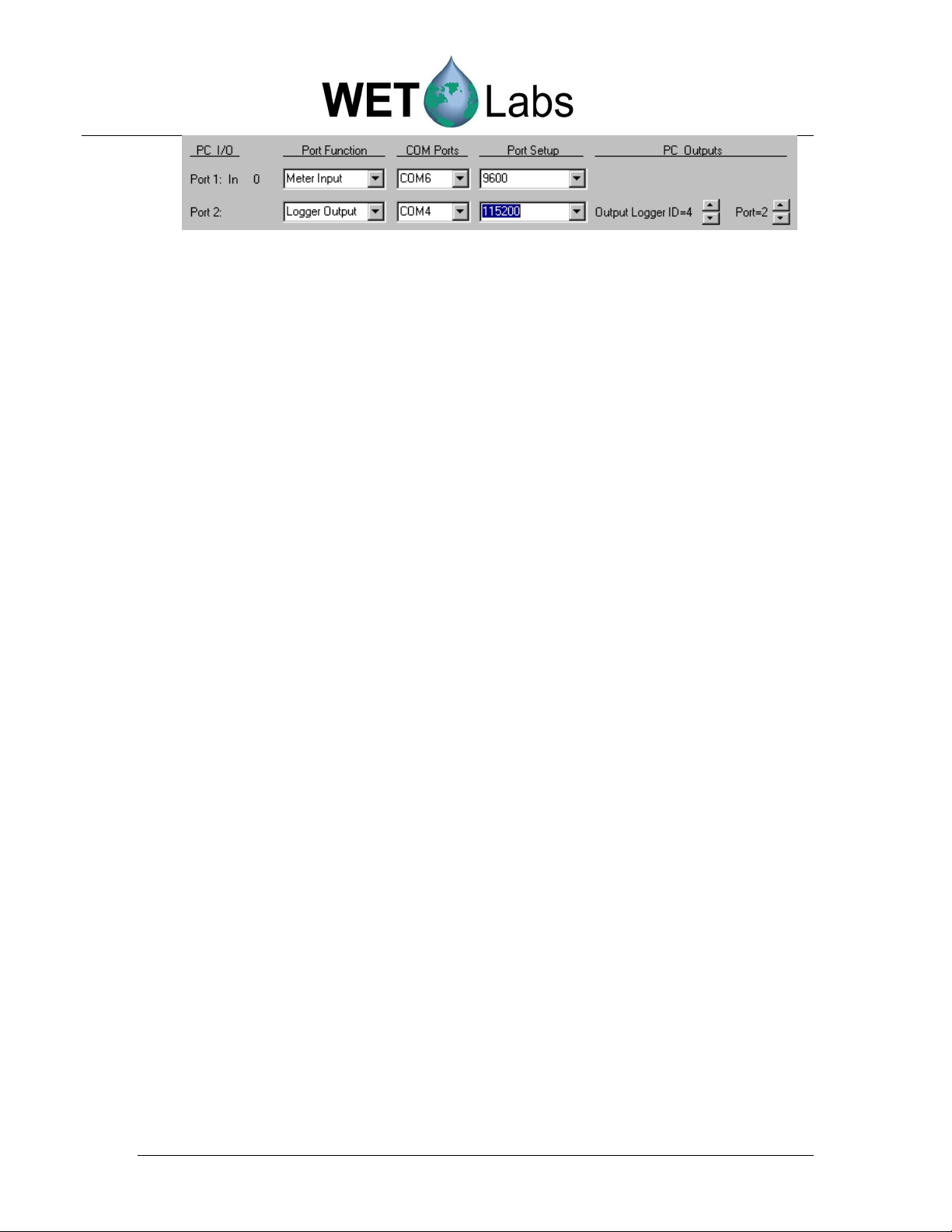
• If a port is selected as
Meter Input
, the data will save only to the host PC
(“virtual logger”), be given a Logger ID=1, and assigned a Port ID
according to its position on the list of available ports. The user will need
to select an available COM port and the port’s baud rate.
• If a port is selected as
Logger Output
, the user must select the COM port,
the data rate, and the data source. The data source can be any of the input
data streams and is identified by the Logger ID (1=PC Logger, 2=DH-4)
and the Ports 1–8.
DH-4 Revision E5 19 June 2006 53
Page 62

Page 63

6. Hardware
The typical DH-4 has the following external connections:
1. Host port/Power input
2. Serial input
3. Serial input
4. Serial input
5. Serial input
6. Battery input
If your configuration varies from this, refer to the Custom Configuration Sheet at the back of this
manual.
6.1 Specifications
Mechanical
Size 7 x 4.1 (17.8 x 10.4 cm)
Pressure housing acetal co-polymer
Weight 4 lbs (1.8 kg) in air; 0.6 lbs (0.3 kg) in water
Deep unit: 5.7 lb (2.6 kg) in air; 2.3 lbs (1 kg) in water
Rated depth 500 or 5000 m
Temperature range 0–30 deg C
Electrical
Input 7–18 VDC
Current draw 0.6 watts @ 12V nominal
Sleep 70 µAmp (max)
Max power 3 Amp @ input voltage
Sample rate 6 scan/sec., nominal
Host interfaces RS-232, RS-422
Data Handling
Serial data input 1–8 ports, RS-232
Analog input 0–5V
Analog input resolution 12 bit A/D
Baud rates 300–115.2K
Data transfer binary
Memory 64 Mb minimum
DH-4 Revision E5 19 June 2006 55
Page 64

6.2 Standard DH-4 Connector Configuration
Sea/Test Cable Co
nnector Pin Function
Serial Connector Socket Function
Battery Connector Pin Function
DH-4 connectors
1 Ground
2 RS-232 (RX)
3 N/C
4 V +
5 RS-232 (TX)
6 N/C
1 Ground
2 V +
3 RS-232 (RX)
4 RS-232 (TX)
1 Ground
2 V +
3 N/C
56 DH-4 Revision E5 19 June 2006
Page 65

6.2.1 Optional Status LED
An optional LED indicates which of the current operating segments the data logger is in
when the user is either not using the host program for status or the user is not in a
position to view the host program.
Regardless of how the data logger is started, the Status LED will flash according to the
following sequences.
Delay: One second on, four seconds off
Pre-Warm Up Flush: One quick flash (50 ms) per second
Warm Up: Two quick flashes per second
Flush: Continuous quick flashes
Sample: One flash (100 ms) every second
Sleep Status LED is off
6.2.2 Magnetic Switch
Some WET Labs data loggers are equipped with a magnetic switch. This is a
logic/control switch, not a power switch for the data logger. Applying power to the data
logger will cause the data logger to become fully active, regardless of the magnetic
switch’s position.
WET Labs uses two different nomenclatures, providing the same utility, for its data
loggers:
older version
newer version
ON (older) or RUN (newer)—Placing the magnetic actuator in the data logger’s RUN or
ON position tells the data logger that start has been selected. If the other steps identified
in Section 5 have been followed, a data sample will begin.
OFF (older) or actuator removed—Removing the actuator from the ON or RUN position
tells the data logger to terminate the current sample if (and only if) the magnetic switch
was used to initiate the sample. The actuator does not need to be placed in an OFF
position to terminate the sample; simply removing the actuator from the ON or RUN
position will provide this function. The OFF position was merely an actuator holder and
is not found on all data loggers.
DH-4 Revision E5 19 June 2006 57
Page 66

6.3 Standard Data Format
6.3.1 Battery.000
The file battery.000 is used to log the battery voltage once per minute or once per moored
sample interval if the sample interval is less than once per minute.
The battery file is also used to log any time periods that the low voltage cut-off has been
exceeded (thus shutting down a sample cycle) and to log if/when the 8-volt limit was
reached, placing the DH-4 into long-term low power sleep.
The battery file has the following format:
10/26/98 21:59:42 12.1
10/26/98 22:01:43 12.1
10/26/98 22:03:43 12.0
10/26/98 22:05:43 12.0
10/26/98 22:07:43 12.0
10/26/98 22:09:43 12.0
10/26/98 22:11:43 12.0
6.3.2 WET Labs Instrument Files
The DH-4 reads, performs basic validations, and stores all valid data records for all the
WET Labs meter. For ac-9s, this includes performing start-to-end packet length and
check sum validations. For ECO meters, this includes finding <CR> and <LF> at the end
of each record.
6.3.3 Non-WET Labs Instruments
In both profile and moored modes, the DH-4 will attempt to read and store all data from a
non-WET Labs instrument No attempt is made to validate the data. While WET Labs
cannot guarantee the DH-4 will be able to read the data from all non-WET Labs
instruments, the DH-4 will have a high rate of success providing there is at least a 50 ms
pause between data records.
6.4 Maintenance
Built for field deployment, the DH-4 requires minimal maintenance. Following these simple
recommendations will assure longer instrument life.
• After a field deployment of the DH-4, thoroughly rinse the instrument prior to
storage.
• Towel-dry the pressure housing.
• Install dummy plugs on all bulkhead connectors.
58 DH-4 Revision E5 19 June 2006
Page 67

Software version:
Firmware version:
Appendix A: Configuration Worksheets
Each DH-4 and ac-9 Plus ships with a Custom Configuration Sheet to assist in understanding the
meter’s initial setup and configurations.
Sample Worksheet
Below is a sample of a configuration sheet using a sample system consisting of a DH-4, an
ac-s, an ECO-VSFS, a CTD, pump, and ECO-FLNTUS.
Configuration settings in the Port Setup and Logger Control tabs may be more easily
tracked by using the worksheet. The worksheet also helps to organize post-processing in
WET Labs Archive Program (WAP).
Port Setup tab
Installed Software and Firmware
7.06
Connector number and class, looking at top of meter
Logger Control tab
7.03a
Connector number and class, looking at bottom of meter
DH-4 Revision E5 19 June 2006 59
Page 68
Required for Logger
Type and S/N
Sampling Parameters
Other setup parameters
Port Setup and Logger Control Tab Settings
Hardware WL Host Software Instrument
DH-4 Bulkhead Required for Port Setup
# (clockwise
from host) Class
Connector 1: A Host Port DH-4 xxx
Connector 2: D 1 ac-s 115200 10 8 Hz ac-s xxx
Connector 3: D 2 ASCII 9600 7.5 1 Hz VSFS xxx
Connector 4: D 3 ASCII 9600 1 Hz CTD
Connector 5: G 4 -- -- -- pump
Connector 6: E -- -- -- -- battery
Connector 7: D 5 ECO-G2 19200 1 Hz FLNTU xxx
Connector 8: D 6 ASCII 19200 1 Hz BB9 xxx
Connector 9: D 7 -- -- --
Connector 10: C
Serial
Port #
9 -- -- --
10 --
Serial Port
Type
Port
Setup
Min.
Volts
Control
Analog/Data
Rate
(For reference)
Sampling Parameters Settings from Configuration Sheet
WL Host Logger Control Settings
Delay before start
Pre-warm up flush
Meter warm-up
Meter flush
Sample
Sample interval
5 sec
10 sec
30 sec
0
2 hrs
4 hrs
Low Voltage Cutoff
(minimum operating V from table above. Use highest value)
Analog/Data Rate
(from table above. Use fastest meter’s data rate.)
10.0 V
8 Hz
60 DH-4 Revision E5 19 June 2006
Page 69

Bulkhead Connector Definition Diagrams
Connector Class A (Host) Connector Class B (Single Analog)
Pin Function Diagram
1 Ground
2 RS-232 RX
3 RS-422 Y
4 V+ (10–18 DC)
5 RS-232 TX
6 RS-422 Z
Socket Function Diagram
1 Ground
2 Analog signal 1
3 Analog 1 ground
4 N/C
5 N/C
6 N/C
Connector Class C (Dual-channel Analog) Connector Class D (Serial)
Socket Function Diagram
1 Ground
2 Analog signal 1
3 Analog 1 ground
5 Analog signal 2
6 Analog 2 ground
Socket Function Diagram
1 Ground
2 V+ (10–18 DC)
3 DH4 RS-232 RX 4 V+ (10–18 DC)
4 DH4 RS-232 TX
Connector E (Battery) Connector F (8-pin Host)
Pin Function Diagram
1
2
3
Ground
V+ (10–18 DC)
N/C
Pin Function Diagram
1 Ground
2 RS-232 RX
3 RS-422 Y
4 V+ (10–18 DC)
5 RS-232 TX
6 RS-422 Z
7 RS-422 A
8 RS-422 B
Connector G (Pump) Connector H (Deep LED/Switch)
Socket
1 Ground
2 V+ (10–18 DC)
3 N/C
Function Diagram Pin Function Diagram
1 LED (-)
2 Switch (+)
3 LED (+)
4 Switch (+)
DH-4 Revision E5 19 June 2006 61
Page 70

Date:
Software version:
Factory
-
set mode:
Firmware version:
Required for Logger
Type and S/N
Sampling Parameters
Other setup parameters
Blank Custom Configuration Worksheet
The blank worksheet below is provided as an aid in the setup of additional or replacement
meters connected to the DH-4.
7.03
Connector number and class, looking at top of meter
Connector number and class, looking at bottom of meter
Hardware WL Host Software Instrument
DH-4 Bulkhead Required for Port Setup
# (clockwise
from host) Class
Connector 1: A Host Port
Connector 2: D 1
Connector 3: D 2
Connector 4: D 3
Connector 5: G 4
Connector 6: E --
Connector 7: D 5
Connector 8: D 6
Connector 9: D 7
Connector 10: C
Serial
Port #
9
10
Serial Port
Type
Port
Setup
Min.
Volts
Control
Analog/Data
Rate
(For reference)
WL Host Logger Control Settings
Delay before start
Pre-warm up flush
Meter warm-up
Meter flush
Sample
Sample interval
62 DH-4 Revision E5 19 June 2006
Low Voltage Cutoff
(minimum operating V from table above. Use highest value)
Analog/Data Rate
(from table above. Use fastest meter’s data rate.)
Page 71

The table below lists supported meters, their data type and rate. See Section 5.1.2 for details.
Port type Data type Rate Port type Data type Rate
ac-9 AC-9 19200 GPS GPS 4800
ac-s AC-S 115200 Hydroscat-2 and -6 ASCII 9600
C-Beta ASCII 9600 LISST-100 and -100-TS ASCII 9600
Depth ASCII 9600 PH meter Analog
DH4 DH4-Mux 115200 Output port Remote-host
ECO (G2) ASCII 19200 SAFire Binary 19200
ECO (G1) VSF-S 9600 Satlantic Binary
FRRF/FRRF-TS ASCII Voltage Analog
CTD-SBE37 and 49 ASCII 9600 WL Flow ASCII 9600
CTD-SBE23 and 43 Analog N/A WETStar Analog 9600
CTD-SBE37SM SBE37-SM 9600
CTD-SD204 (SAIV) ASCII 9600
Connector Class A (Host) Connector Class B (Single Analog)
Pin Function Diagram
1 Ground
2 RS-232 RX 2 Analog signal 1
3 RS-422 Y 3 Analog 1 ground
4 V+ (10–18 DC) 4 N/C
5 RS-232 TX 5 N/C
6 RS-422 Z 6 N/C
Socket Function Diagram
1 Ground
Connector Class C (Dual-channel Analog) Connector Class D (Serial)
Socket Function Diagram Socket Function Diagram
1 Ground
2 Analog signal 1 2 V+ (10–18 DC)
3 Analog 1 ground
5 Analog signal 2
1 Ground
3 DH4 RS-232 RX 4 V+ (10–18 DC)
4 DH4 RS-232 TX 6 Analog 2 ground
Connector E (Battery) Connector F (8-pin Host)
Pin Function Diagram
1 Ground
2 V+ (10–18 DC) 2 RS-232 RX
3 N/C 3 RS-422 Y
1 Ground
4 V+ (10–18 DC)
5 RS-232 TX
6 RS-422 Z
7 RS-422 A
8 RS-422 B
Pin Function Diagram
Connector G (Pump) Connector H (Deep LED/Switch)
Pin Function Diagram Pin Function Diagram
1 Ground
2 V+ (10–18 DC) 2 Switch terminal
3 N/C 3 LED (+)
1 LED (-)
4 Switch terminal
DH-4 Revision E5 19 June 2006 63
Page 72

Appendix B: Real-Time Data Format
The data logger format consists of sequence binary data packets that incorporate a packet time
stamp, data from all ports for the current time interval, and a packet check sum to allow
validation on the receiving end. The header and Check Sum bytes are stripped off each packet
before it is saved as a WET Labs Archive file.
The DH-Mux packet format is:
Function Size (bytes) Default/Range of values
Header 2 0x0808 Always
Destination 1 0x01 Always
Packet Type 1 0x00-0x01 0x00=pre 6.0, 0x01=6.07 and later
Sender 1 0x00-0x04 0x02—Used for time corrections
Modulus 1 0x00-0xFF Increments by 1 each packet
Data Length 2 0x00-0x0960 0–1024
Time 4 Packet time in ms or 100th/second
Channel 1 Size 2 Number of bytes from Serial 1
Channel 2 Size 2 Number of bytes from Serial 2
Channel 3 Size 2 Number of bytes from Serial 3
Channel 4 Size 2 Number of bytes from Serial 4
Channel 5 Size 2 Number of bytes from Serial 5
Channel 6 Size 2 Number of bytes from Serial 6
Channel 7 Size 2 Number of bytes from Serial 7
Channel 8 Size 2 Number of bytes from Serial 8
Analog Size 2 Number of bytes from all Analog Ports
Data 0-1024 Data laid out in order Channel 1–8 + analog
Pads 4 ‘####’ Pad characters
Check Sum 2 Summation of all bytes from Header-Data
Note: the archive file packet is the same as the real-time format except the Header and Check
Sum are not present.
64 DH-4 Revision E5 19 June 2006
Page 73

Appendix C: File Handling
The data logger ships with the following file types:
•
.wlh: wet labs host, the factory-set defaults for the host program software
•
.lst: logger setup file, containing the instrument settings for the data logger firmware
•
.plt: plot setup files
•
.hdw: hardware setup files
•
.alg: analog setup files
The .wlh and .lst file extensions are typically the only types used. When you press Get Setup in
the host program, you are loading a .lst file with the logger’s last saved settings. You may
overwrite those settings by changing configurations in the host software and pressing Send
Setup, thus changing the firmware. If you choose to save those configurations, pressing Save
Setup File will save the file as a .wlh file. This can be retrieved at a later date by selecting Open
Setup File. When you select Get Setup, the last configurations sent to the logger will be used.
If you do not need to change the factory default settings, you need only select Get Setup each
time you use the data logger.
DH-4 Revision E5 19 June 2006 65
Page 74

Revision
Date
Revision Description
Originator
Revision History
A 3/9/00 Release v. 7 host software (S/N 020 and above)
(DCR 33)
B 3/26/01 Add ASCII Archive Files to host software data
options (DCR 100)
C 1/2/02 Correct pinouts for v.7 (DCR 174) S. Mole
D 5/6/04 Update user’s guide and software (DCR 387) D. Romanko
E 10/14/04 Correct class D connector pin-out and ac-9 data
rate (DCR 434)
E1, E2,
E3
E5 6/19/06 Finalize software updates (DCR 501) (pending
4/28/05,
11/21/05,
6/12/06
Updates to reflect v. 7.03, 7.06 software M. Levin, D. Stahlke,
approval)
D. Romanko
D. Romanko
A. Barnard
H. Van Zee
D. Romanko, D. Stahlke,
H. Van Zee
DH-4 Revision E5 19 June 2006
 Loading...