

Page 1
Operating Instructions and Parts Manual
Please read and save these instructions. Read carefully before attempting to assemble, install, operate or maintain the product described.
Protect yourself and others by observing all safety information. Failure to comply with instructions could result in personal injury and/or
property damage! Retain instructions for future reference.
1JYT9A, 1JYU1A, 1JYU2A and 1JYU3A
Description
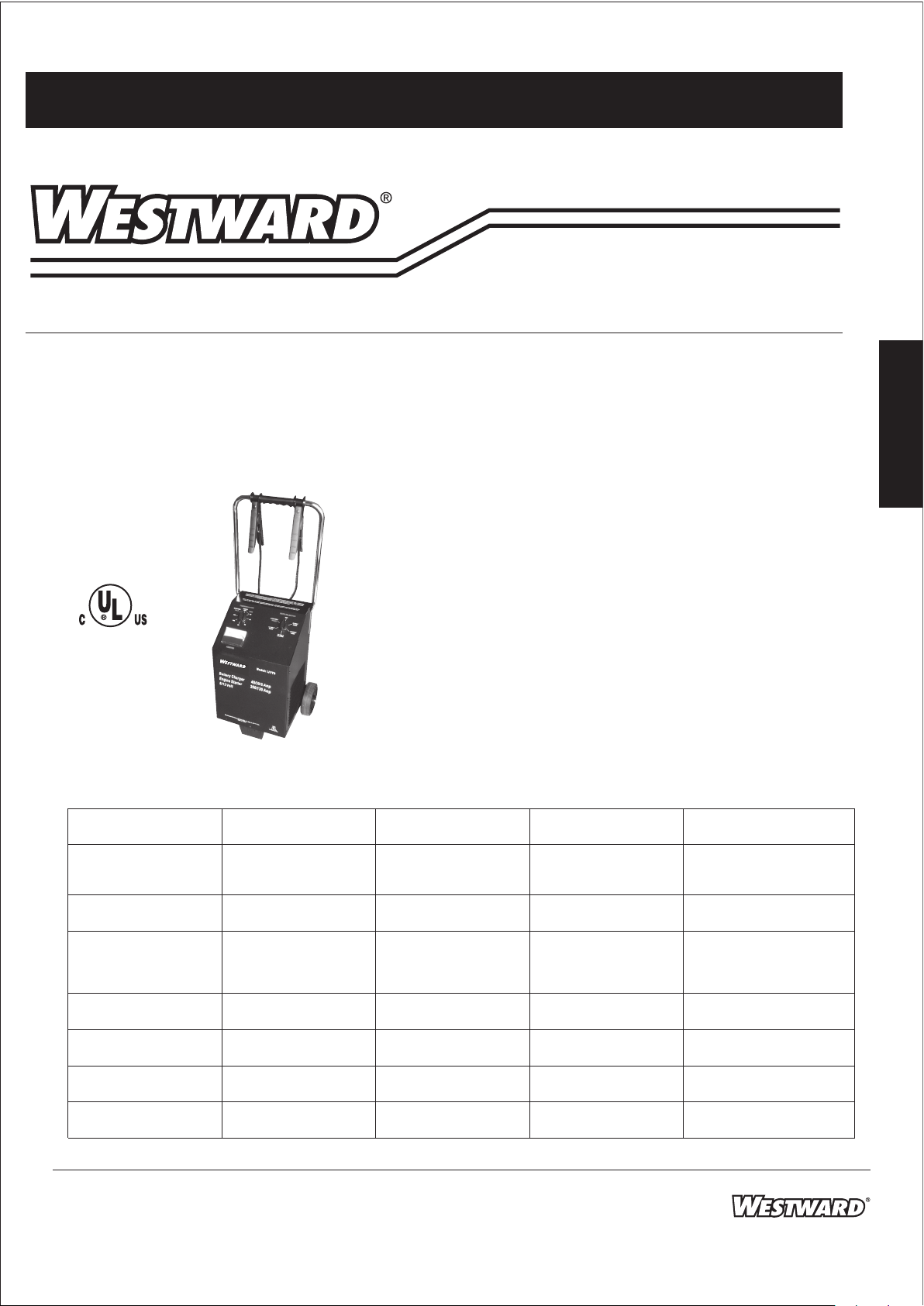
Westward battery chargers are mobile oor units designed to deliver maximum
starting power. They charge up to 60 amperes (maximum) on 6 or 12 volt batteries
(1JYT9A max 40 amps).
Chargers are equipped with a timer control, charging voltage and rate selector,
ammeter and automatic reset circuit breaker.
Figure 1
Specications 1JYT9A 1JYU1A 1JYU2A 1JYU3A
Power Supply
Requirements
Primary AC
input@ rated
12 V output
Max Continuos
Charge Output
Start Output
@7.2V
Medium charge
output
Motorcycle or
nishing charging
Average
Charging Time
Primary AC
input@start
120 VAC,
60 Hz
8.5 Amps
@120V
60 Hz
40 Amps
@6/12V
200 Amps
@7.2V
130 Amps
@6V
20 Amps
@12V
2 Amps
@12V
3/4 to 1/2 hr
29 Amps
120 VAC,
60 Hz
12.0 Amps
@120V
60 Hz
60 Amps
@6/12V
250 Amps
@7.2V
185 Amps
@6V
40 Amps
@12V
2 Amps
@12V
1/2 to 1 hr
43 Amps
Important Safety
Instructions
READ THESE FIRST
1. SAVE THESE INSTRUCTIONS.
This manual contains important
safety and operating instructions.
2. Do not expose charger to rain or
snow.
3. Use of an attachment not
recommended or sold by the
manufacturer may result in a risk of
re, electric shock, or injury to
persons.
4. To reduce risk of damage to electric
plug and cord, pull by plug rather
than cord when disconnecting
charger.
5. An extension cord should not be
used unless absolutely necessary.
120 VAC,
60 Hz
12.0 Amps
@120V
60 Hz
60 Amps
@6/12V
250 Amps
@7.2V
185 Amps
@6V
0-60 Amps
@6/12V
0-3 Amps
@6/12V
1/2 to 1 hr
58 Amps
120 VAC,
60 Hz
12.0 Amps
@120V
60 Hz
60 Amps
@6/12V
225 Amps
@7.2V
160 Amps
@6V
40 Amps
@12V
Not
Applicable
1/2 to 1 hr
35 Amps
E
N
G
L
I
S
H
30 Amps
@24V
Form 5S4079
Printed in Taiwan
05/10 JL06
Page 2

Westward Operating Instructions and Parts Manual
®
Westward
Battery Chargers
1JYT9A, 1JYU1A, 1JYU2A and 1JYU3A
Important Safety Instructions
E
N
G
L
I
S
H
(Continued)
Use of improper extension cord could
result in a risk of re and electric
shock.
If extension cord must be used, make
sure that the extension cord plug pins
are the same number, size, and shape
as the charger plug, that the
extension cord is properly wired and
in good electrical condition, and that
the wire size is large enough for the
length of cord as specied in the
following chart:
Length of AWG size
cord in feet of cord
25 16
50 12
100 10
150 8
6. Do not operate charger with
damaged cord or plug. Replace the
cord or plug immediately.
7. Do not operate charger if it has
received a sharp blow, been dropped,
or otherwise damaged in any way;
take it to a qualied service person.
8. Do not disassemble charger; take it to
a qualied service person when
service or repair is required. Incorrect
reassembly may result in a risk of
electric shock or re.
9. To reduce risk of electric shock,
unplug charger from outlet before
attempting any maintenance or
cleaning. Turning o controls will not
reduce this risk.
vicinity of a lead acid battery is
dangerous. Batteries generate
explosive gases during normal battery
operation. For this reason, it is of
utmost importance that each time
before using your charger, you read
this and follow the instructions exactly.
To reduce risk of battery explosion,
follow these instructions and those
published by battery manufacturer and
manufacturer of any equipment you
intend to use in vicinity of battery.
Review cautionary markings on these
products and in engine compartment.
PERSONAL PRECAUTIONS
1. Someone should be within range of
your voice or close enough to come
to your aid when you work near a
lead acid battery.
2. Have plenty of fresh water and soap
nearby in case battery acid contacts
skin, clothing, or eyes.
3. Wear complete eye protection and
clothing protection. Avoid touching
eyes while working near battery.
4. If battery acid contacts skin or
clothing, wash immediately with soap
and water. If acid enters eye,
immediately ush eye with running
cold water for at least 10 minutes and
get medical attention immediately.
5. NEVER smoke or allow a spark or
ame in vicinity of battery or engine.
6. Be extra cautious to reduce risk of
dropping a metal tool onto battery. It
might spark or short-circuit battery or
other electrical part that may cause
explosion.
RISK OF EXPLOSIVE
GASES. Working in
7. Remove personal metal items such as
rings, bracelets, necklaces, and
watches when working with a leadacid battery. A lead-acid battery can
produce a short-circuit current high
enough to weld a ring or the like to
metal, causing a severe burn.
8. Use charger for charging LEAD-ACID
battery only. It is not intended to
supply power to a low voltage
electrical system other than in a
starter-motor application. Do not use
battery charger for charging dry-cell
batteries that are commonly used
with home appliances. These
batteries may burst and cause injury
to persons and damage to property.
9. NEVER charge a frozen battery.
PREPARING TO CHARGE BATTERY
1. If necessary to remove battery from
vehicle to charge, always remove
grounded terminal from battery rst.
Make sure all accessories in the
vehicle are o, so as not to cause an
arc.
2. Be sure area around battery is well
ventilated while battery is being
charged. Gas can be forcefully blown
away by using a piece of cardboard
or other nonmetallic material as a
fan.
3. Clean battery terminals. Be careful to
keep corrosion from coming in
contact with eyes.
4. Add distilled water in each cell until
battery acid reaches level specied by
battery manufacturer. This helps
purge excessive gas from cells. Do not
overll. For a battery without cell
caps, carefully follow manufacturer’s
recharging instructions.
2
Page 3
Westward Operating Instructions and Parts Manual
Models 1JYT9A, 1JYU1A, 1JYU2A and 1JYU3A
Important Safety Instructions
(Continued)
5. Study all battery manufacturer’s specic precautions such as removing or
not removing cell caps while charging
and recommended rates of charge.
6. Determine voltage of battery by
referring to car owner’s manual and
make sure that output voltage
selector switch is set at correct
voltage.
LOCATING THE CHARGER
1. Locate charger as far away from
battery as DC cables permit.
2. Never place charger directly above
battery being charged; gases from
battery will corrode and damage
charger.
3. Never allow battery acid to drip on
charger when reading gravity or
lling battery.
4. Do not operate charger in a closed
area or restrict ventilation in any way.
5. Do not set a battery on top of
charger.
GROUNDING AND AC POWER CORD
CONNECTIONS
Charger should be grounded to reduce
risk of electric shock. Charger is
equipped with an electric cord having
an equipment-grounding conductor
and grounding plug. The plug must be
plugged into an outlet that is properly
installed and grounded in accordance
with all local codes and ordinances.
Never alter AC cord
or plug provided. If it
will not t outlet, have proper outlet
installed by a qualied electrician.
Improper connection can result in risk
of an electric shock.
Connect and
disconnect DC
output clips only after setting any
switches with an OFF position to OFF
and removing AC cord from electric
outlet. Never allow clips to touch each
other.
BATTERY CHARGER CONNECTION
PRECAUTIONS
1. When hooking up charger, attach
one clip to battery and the other to a
point away from battery (see
“Charging a Battery Installed in
Vehicle”, and “Charging a Battery
Outside the Vehicle”). Do not hook
up charger until reading the entire
manual. To reduce explosion risk,
never connect both clips directly to
the battery. When making each
connection, twist or rock clip back
and forth several times to make a
good connection and to reduce the
risk of a clip slipping o and creating
a spark. Do not twist or rock clip on
the battery after the second clip
connection is made.
CHARGING A BATTERY INSTALLED IN
VEHICLE
A marine (boat)
battery must be
removed and charged on shore. To
charge it on board requires equipment
specially designed for marine use.
A spark near
battery may cause
battery explosion. To reduce risk of a
spark near battery:
1. Position AC and DC cords to reduce
risk of damage by hood, door, or
moving engine part.
2. Stay clear of fan blades, belts, pulleys,
and other parts that can cause injury
to persons.
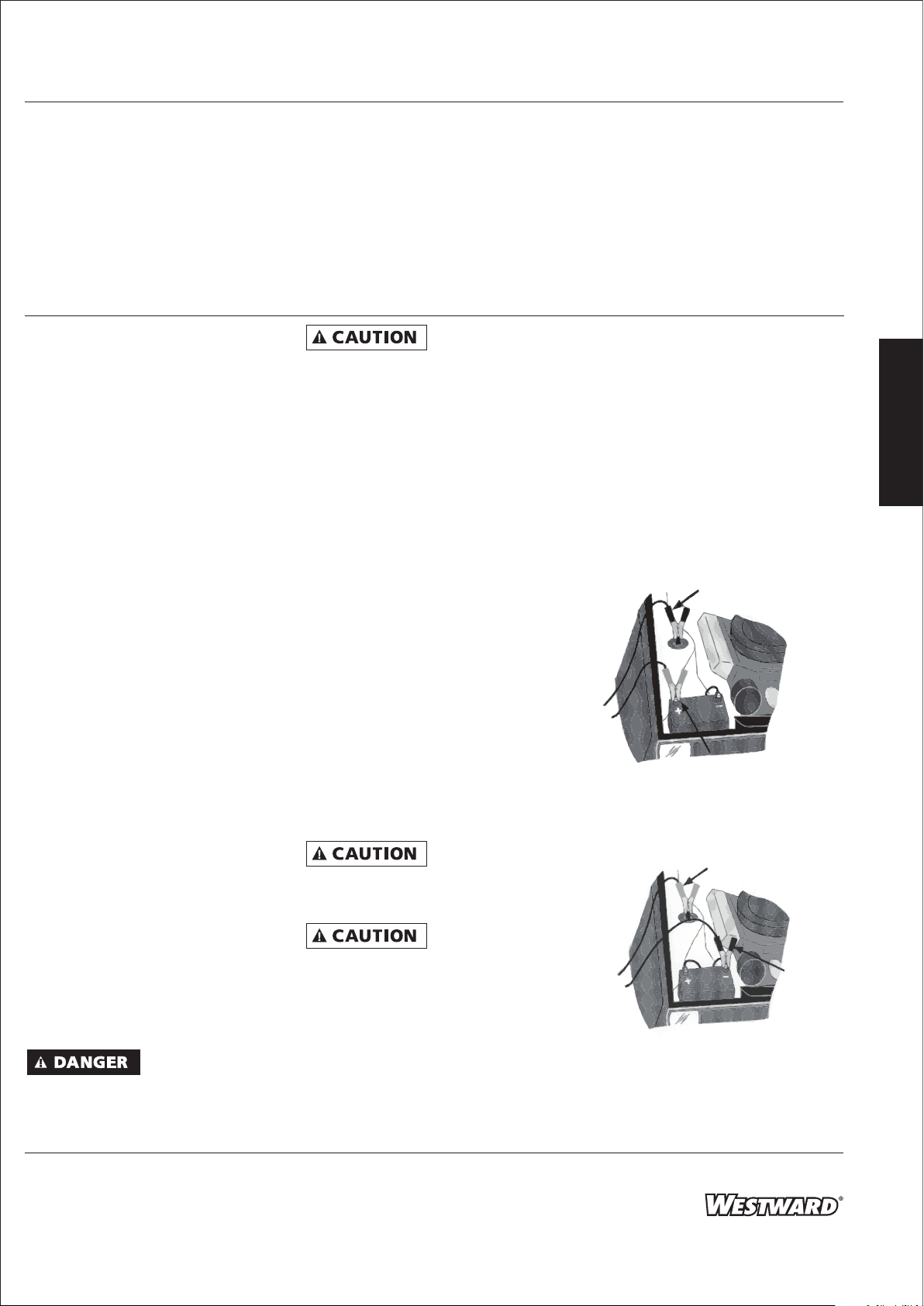
3. Check polarity of battery posts.
POSITIVE (POS, P, +) battery post
usually has larger diameter than
NEGATIVE (NEG, N, -) post.
4. Determine which post of battery is
grounded (connected) to the chassis.
If the negative post is grounded to
the chassis (as in most vehicles), see
Figure 2 and instruction “5a”. If the
positive post is grounded to the chassis, see Figure 3 and instruction “5b”.
Negative to
Chassis Ground
Positive
Figure 2
Positive to Chassis
Ground
Figure 3
E
N
G
L
I
S
H
Negative
3
Page 4
Westward Operating Instructions and Parts Manual
®
Westward
Battery Chargers
1JYT9A, 1JYU1A, 1JYU2A and 1JYU3A
Important Safety Instructions
E
N
G
L
I
S
H
(Continued)
5. a. For NEGATIVE-GROUNDED vehicle,
connect POSITIVE (red) clip from the
battery charger to the POSITIVE (POS,
P, +) ungrounded post of the battery.
b. For POSITIVE-GROUNDED vehicle,
connect the NEGATIVE (black) clip
from the battery charger to the
NEGATIVE (NEG, N, -) ungrounded
post of the battery.
6. Connect the remaining battery
charger clip to the vehicle chassis or
engine block, as far away from the
battery as possible. Do not connect
the clip to carburetor, fuel lines, or
sheet-metal body parts. Connect to a
heavy-gauge metal part of the frame
or engine block.
7. When disconnecting charger, turn all
switches with an OFF position to OFF,
disconnect AC cord, remove clip from
vehicle chassis, and then remove clip
from battery terminal.
CHARGING A BATTERY OUTSIDE THE
VEHICLE
A spark near the
battery may cause
battery explosion. To reduce risk of a
spark near battery:
1. Check polarity of battery posts.
POSITIVE (POS, P, +) battery post
usually has a larger diameter than
NEGATIVE (NEG, N, -) post.
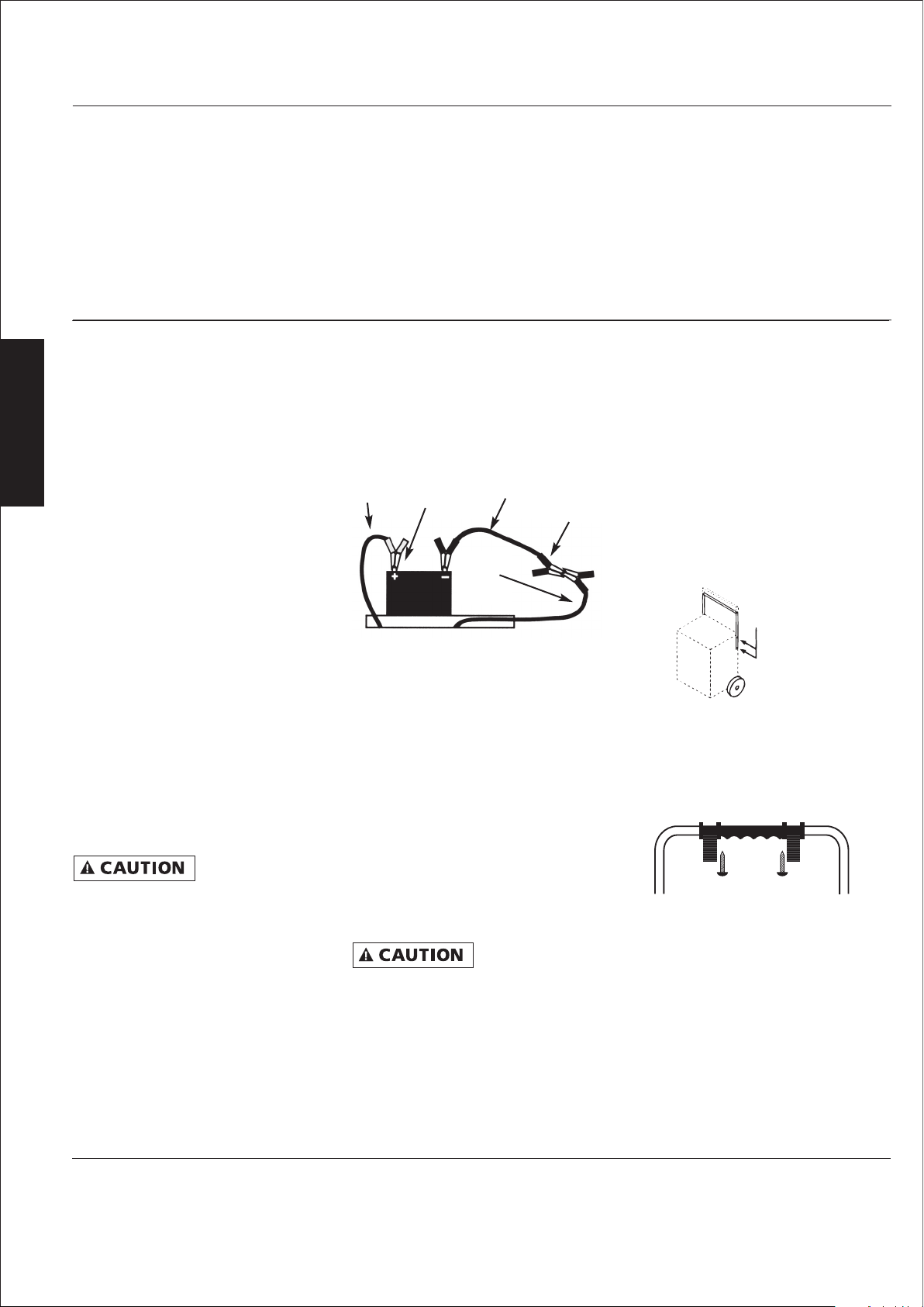
2. Attach a cable (not provided) to the
NEGATIVE (NEG, N, -) battery post.
This cable must be a minimum of 24”
long, and of a wire gauge that is no
lighter than the wire gauge of the
charger’s output cables (battery
cables and booster cables work well)
(See Figure 4).
Cable
from
Charger
Figure 4
3. Connect POSITIVE (red) charger clip to
POSITIVE (POS, P, +) post of battery.
4. Position yourself and the free end of
the cable (installed in Step #2) as FAR
away from the battery as possible.
FACING AWAY FROM THE BATTERY,
connect the NEGATIVE (black) charger
clip to the free end of the cable.
5. When disconnecting charger, always
do so in reverse sequence of
connecting procedure and break rst
connection while as far away from
battery as practical.
before operating! The wheels and foot
must be installed to provide proper
clearance for ventilation. Failure to
provide clearance may result in severe
overheating and may cause damage to
the charger and the surrounding area.
Positive
Booster
Cable
Negative
Cable
from
Charger
The charger must
be fully assembled
Assembly
1. Assemble the charger according to
the following instructions and Figures
5 and 6.
2. Carefully, remove the charger and
parts bag from carton.
3. Stand charger upright and rotate
handle upward aligning mounting
holes on handle to holes on cabinet.
Secure with self-tapping screws
and tighten all handle screws
(see Figure 5).
Tighten down
Screws to
Cabinet
Figure 5 – Install Handle
4. Remove clamp holders from
hardware bag. Snap the two pieces
together onto the handle and secure
with 2 machine screws (see Figure 6).
Figure 6 – Install Clamp Holder
5. Assembly is now complete.
4
Page 5
Westward Operating Instructions and Parts Manual
Models 1JYT9A, 1JYU1A, 1JYU2A and 1JYU3A
Operation
6/12 V
START
12 V
HIGH
OFF
12 V
MEDIUM
6 V
HIGH
12 V
LOW
6/12 V
START
12 V
HIGH
OFF
12 V
MEDIUM
6 V
HIGH
12 V
LOW
MINIMUM START
24 V
HIGH
12 V
HIGH START
OFF
OFF
6 V
HIGH START
12 V
MEDIUM
E
N
G
L
I
S
H
1JYT9A
Figure 7
CHARGING TIME INSTRUCTIONS
1. Determine battery percent of charge
(or specic gravity) with hydrometer
or electronic tester.
2. Note specic gravity or percent of
charge on the following chart. Use
column nearest the Ammeter reading
observed.
Hydrom-
Reading
(Battery
Specic
Gravity)
Ammeter Reading
eter
1.265
1.225
1.190
1.155
1.120
Battery
Tester
Reading
(Percent
Charge)
100%
75%
50%
25%
0%
6 Volt
Battery
Charging
Time
(Minutes)
60
Full Charge Full Charge
27
55
85
110
12 Volt
Battery
Charging
Time
(Minutes)
60 40 20
15
20
35
45
50
65
65
85
3. Charge battery for the time indicated
on the chart. A more precise method
of determining length of charge time
requires the use of the following
formulas, the reserve Capacity or
Ampere Hour rating of the battery,
and the percent of charge needed to
bring the battery to full charge.
400
800
1200
1600
1JYU1A 1JYU2A 1JYU3A
4. If the only battery rating known is
Reserve Capacity, you must rst
convert it to Ampere Hours using the
following formula:
Amp
hour
Reserve
size of
Capacity (min)
=
2
+
15.5
NOTE: Express the percent of charge
needed as a decimal (25% = .25). Amp
output for charge rate settings: 12V
Low = 2 Amps, 12V Medium = 40 Amps,
6 or 12V High = 60 Amps.
Percent of charge needed = 25%
or .25.
Battery
Example: Reserve Capacity of
.25 x 45.5
10
x 1.25
Battery = 60 Minutes
60
hour
2
=+
15.5 45.5 Ampere
5. With the battery Ampere Hour rating
and the percent of charge needed to
bring the battery to full charge, use
the following formula to determine
length of charge time of battery
selected on charger:
Amp
Hour
Rating
% of Charge
x
Needed
Amp Setting
x
=
1.25
Hours
Charge
6. Plug charger supply cord into 120V,
60 Hz, outlet, set charging rate
selector for ammeter reading closest
to chart column used, timer will shut
charger OFF when charging cycle is
complete.
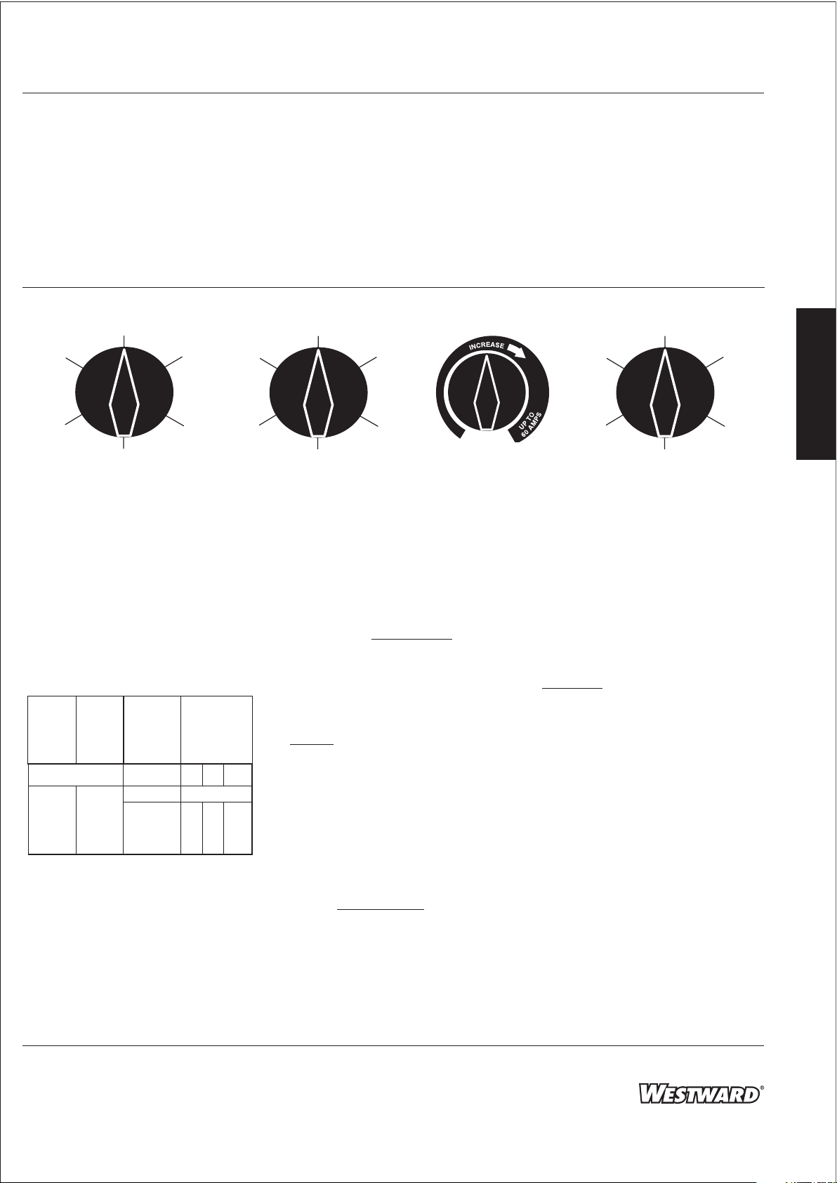
CHARGER CONTROLS
MODELS 1JYT9A & 1JYU1A
Refer To Figure 7
The switch on the front of your charger
To
is used to select the voltage and rate of
charging. Listed below are the settings
and typical uses for each. (Clockwise
from top):
1.42 Hours
=
To Charge
5
5
Page 6

Westward Operating Instructions and Parts Manual
®
Westward
Battery Chargers
1JYT9A, 1JYU1A, 1JYU2A and 1JYU3A
Operation (Continued)
E
N
G
L
I
S
H
OFF - Shuts o power to charging
portion of charger; does not remove
power from the entire unit.
6V High - Provides up to 60 amps for 6
volt batteries, 40 amps on 1JYT9A.
12V Low - Provides a charge of 2 amps
for 12 volt batteries. Good for small
batteries on motorcycles, lawn
equipment, etc. Also used for restoring
sulfated batteries by charging for
extended periods at low rate.
12V Medium - Provides a maximum
charge of 40 amps (N/A for 1JYT9A) for
charging calcium-style batteries or
others that cannot withstand higher
rates of charge.
12V High - Provides up to 60 amps, 40
amps on 1JYT9A for 12 volt batteries.
6V & 12V Engine start - This setting is
used for starting 6V & 12V vehicles.
MODEL 1JYU3A
Refer To Figure 7
6V High & Start - Provides up to 60
amps for charging and starting 6 volt
batteries.
12V Medium - Provides a maximum
charge of 40 amps for charging calciumstyle batteries or others that cannot
withstand higher rates of charge.
12V High & Start - Provides up to 60
amps charging and starting power for
12 volt batteries.
24V High - Provides up to 30 amps
charging and starting power for 24 volt
batteries.
MODEL 1JYU2A
Your model 1JYU2A battery charger is a
manual to fully automatic charger with
a 2 hour timer (for use in manual
mode), and an innite amperage
control that allows a selection of any
charge rate up to 60 amps. It has a test
feature that allows you to test for
percent of charge, alternator
performance, and problem conditions
such as sulfated or shorted batteries.
TIMER/MODE SELECTOR
The 1JYU2A TIMER/MODE SELECTOR sets
the charger to manual mode and allows
the selection of any charging time up to
120 minutes. In manual mode (no time
set in), charging is controlled by the
RATE SELECTOR. When the time is up,
the charger will switch to a 15 amp
automatic on/o mode that will start
and stop the charger, as the battery
requires, until the battery is fully
charged. The charger will shut o when
the battery is at full charge. If left
connected, the charger will continue to
monitor the battery and will
automatically begin charging again if
the battery drops below full charge. To
charge a battery in automatic mode,
return the timer to automatic (no time
set into the timer). THE RATE SELECTOR
will no longer be in control of charging.
The automatic charge rate is 15 amps.
Do not charge motorcycle and garden
tractor, etc. batteries in automatic
mode. Charge in manual mode only,
2 amps maximum.
VOLT SELECTOR
Allows the selection of 6 Volt or 12 Volt
charging. This switch also has a center
OFF position to turn the charger OFF.
GENERAL CHARGING INFO FOR ALL
MODELS
As the battery becomes more fully
charged, the rate of charge tapers
down. Depending on the battery
percent of charge, the amperage that
the charger delivers when starting to
charge will vary. It will usually be less
than the amperage selected unless the
battery is almost fully discharged.
Always make sure that the selection you
make matches the voltage of the
battery being charged.
When charging small 12 volt batteries,
like those used in garden tractors,
snowmobiles, motorcycles, and ATV's,
always select the 12 volt/2 amp setting.
Small batteries like these can be
damaged by higher rates of charge.
ENGINE START FUNCTION
For starting engines, connect the
charger as you normally would, charge
the battery for 5-10 minutes, set
selector to start and then crank the
engine.
When the starter engages, the charger
will deliver starting power to
supplement the battery to start the
vehicle. Do not crank for more than 5
seconds as overheating of the vehicle
starter, cables, and battery charger can
occur. After allowing to cool for 3-4
minutes, cranking can be repeated. The
charger is protected from overheating
by a thermal protector. This is for the
protection of both the charger and the
vehicle. If the thermal protector trips,
wait until the charger resets
automatically (about 3-4 minutes) and
resume cranking.
6
Page 7
Westward Operating Instructions and Parts Manual
Models 1JYT9A, 1JYU1A, 1JYU2A and 1JYU3A
Operation (Continued)
NOTE: Problems in a vehicle's fuel,
ignition, or other systems may prevent
the vehicle from starting. The problem
area will need to be serviced before the
vehicle can be started.
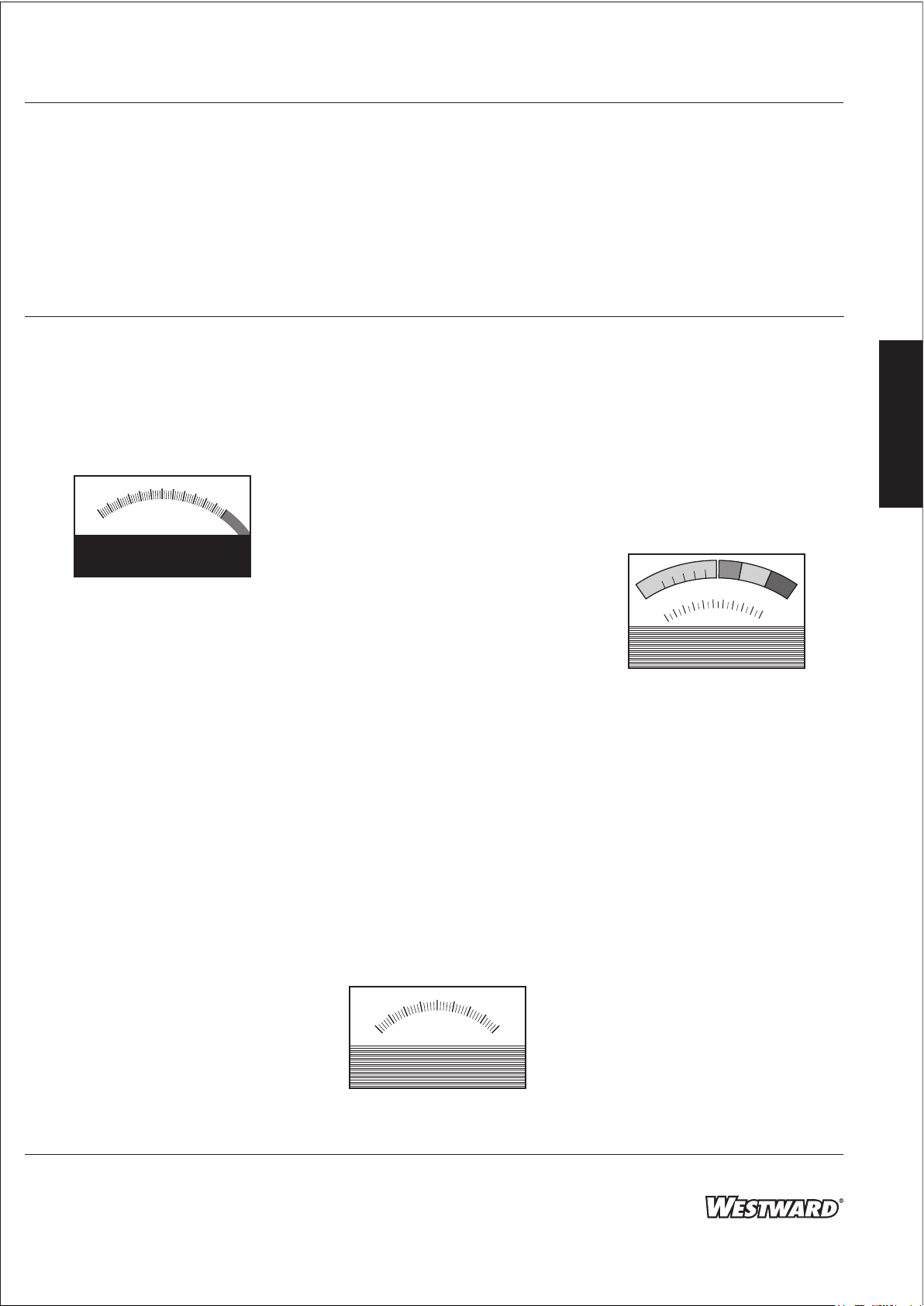
AMMETER
30
40
20
10
0
AMPS
Figure 8
The ammeter on the front of the
charger (see Figure 8) indicates the
amount of amperes owing from the
charger into the battery. As the battery
nears full charge, the charge rate
lessens and the ammeter needle moves
towards lower ampere values. Model
1JYU2A also has green and red lights
installed within the ammeter. The green
light is lit when the battery is at full
charge. The red light indicates that the
battery cables are connected backwards
(takes six seconds before the light will
come on).
When the battery being charged is cold
(temperatures less than 32ºF (0ºC) the
battery will not accept high rates of
charge until it warms up. The initial
charge rate will be low and, as the
battery warms up through charging, the
rate will increase.
The same conditions exist if the battery
being charged is sulfated. Sulfated
batteries cannot accept high charge
rates because the internal plates of the
battery are coated with lead sulfate.
This occurs when a battery is left in a
discharged state for a long time. This
50
60
battery condition can sometimes be
cured. The battery can have at least
some of the sulfate removed by
charging on the 2 amp setting (12 volt
only) for a long period of time. Refer to
the battery manufacturer's instructions
for the proper methods of removing
sulfate.
When the battery being charged has a
short circuit, the ammeter will show
that the charger is putting out full
current. If, after 5-10 minutes, the
needle has not moved, unplug the
charger and discontinue charging.
NOTE: If the needle drops to zero, the
internal circuit breaker has tripped and
will reset automatically after 3-4
minutes. Use a voltmeter and read the
voltage of the battery. If the voltage is
under 11.5 volts, the battery is probably
defective and should be serviced or
replaced. If the voltage reads over 11.5
volts, plug the charger back in and
continue charging. If, after 15-20
minutes, the needle on the meter still
has not moved, repeat the voltmeter
test. If no change in voltage has
occurred, the battery needs service or
replacing.
During Engine Start, the needle will
move into the red Engine Start section
of the meter. This will occur when the
vehicle starter is engaged.
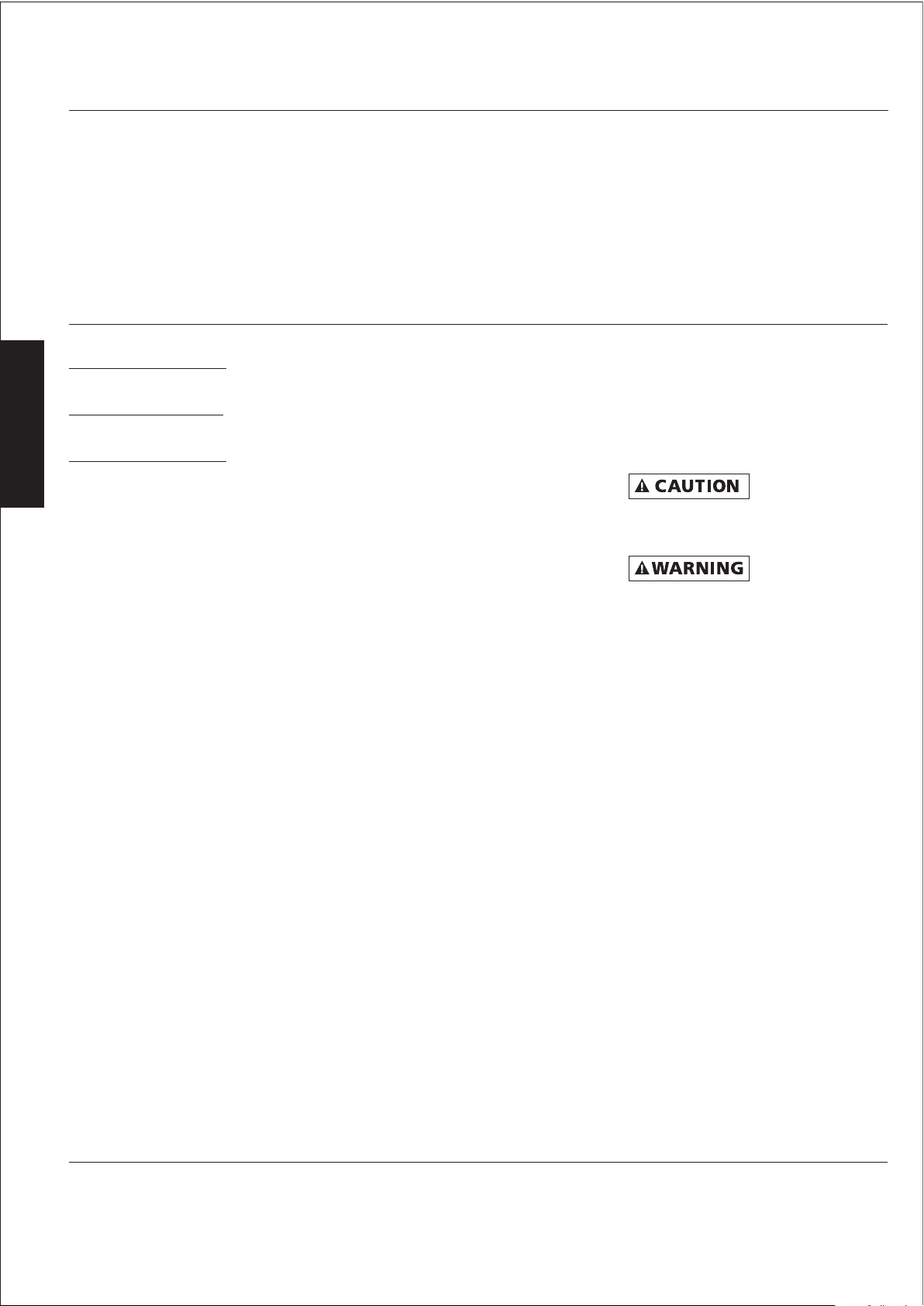
VOLTMETER (1JYU3A ONLY)
20
30
40
Figure 9
10
0
VOLTS
The voltmeter (Figure 9) will indicate
voltage whenever the charger is turned
on, or when the clamps are connected
to a battery. If connected to a battery
and on, it will read the combined
voltage of the battery and the charger.
If you get no reading when connected
to a battery, check your connections
and/or your battery.
TEST METER/VOLTMETER
(1JYU1A AND 1JYU2A ONLY)
100
75
LOW
0
%
50
25
R
A
H
C
f
o
6
4
2
0
DC VOLTS
E
G
8
OK
A
12
10
HIGH
L
E
R
N
A
T
O
R
T
14
E
16
S
18
T
20
Figure 10
The combination test meter/voltmeter
on the front of the charger (see Figure
10) is used to read the voltage across
the battery charger clamps.
In normal operation, without the Test
Switch depressed, the meter reads from
0-20 DC volts, on the lower scale of the
meter. Using this part of the meter,
during charging, the voltages should
read:
6 Volt Batteries 6.5 to 8.5 Volts
12 Volt Batteries 13.5 to 16.5 Volts
24 Volt Batteries 27.0 to 33.0 Volts
(1JYU3A Only)
If the voltmeter reads outside of these
voltages, refer to the listings below for
possible battery conditions:
E
N
G
L
I
S
H
7
Page 8
Westward Operating Instructions and Parts Manual
®
Westward
Battery Chargers
1JYT9A, 1JYU1A, 1JYU2A and 1JYU3A
Operation (Continued)
E
N
G
L
I
S
H
Volts Low, Amps High
Probable Shorted Battery – Replace
Volts Low, Amps Low
Poor Connection or Frozen Battery
Volts High, Amps Low
Battery Cold or Sulfated – Reduce
charge rate and charge longer.
After charging is complete, the
voltmeter should read the full charge
voltage of the battery. This is normally
higher than the rated battery voltage.
TEST SWITCH (1JYU1A AND 1JYU2A
ONLY)
By depressing the Test Switch, the
voltmeter changes into a more precise
mode. This precision is necessary to read
battery charge levels.
BATTERY PERCENT OF CHARGE TEST
(12 VOLT ONLY) 1JYU1A AND 1JYU2A
ONLY
1. With the charger OFF and clamps
properly connected to the battery,
depress the Test Switch and read the
Battery Percent of Charge on the top
left scale of the Test Meter.
2. If the battery has been recently
charged or is in a vehicle that has
been run recently, there is probably a
“surface charge” on the battery. This
will give a falsely high reading on the
Percent of Charge Test. Remove the
“surface charge” by turning on the
vehicle headlights for 3 or more
minutes. Allow the battery to sit for 1
minute. Then re-test the Battery
Percent of Charge.
ALTERNATOR TEST (12 VOLT ONLY)
1JYU1A AND 1JYU2A ONLY
1. With charger OFF and clamps
properly hooked to the battery, start
the engine and while running it at
fast idle, depress the Test Switch.
2. Read the alternator condition on the
Alternator Test scale at the upper
right section of the Test Meter. The
battery should be in a good state of
charge before attempting this test.
3. The three zones of the meter indicate
the following:
OK –Charging system is
performing properly
LOW –Loose fan belt, or voltage
regulator and/or alternator
faulty
HIGH –Faulty voltage regulator or
wiring harness
NOTE: This type of repair work is rather
specialized. It may require additional
tests on additional instruments for
complete diagnosis.
IMPORTANT: The charger must be
turned OFF to perform the tests. If
attempting to test with the charger
turned ON, the results will be
meaningless.
TIMER CONTROL
The timer on the front of your charger
allows you to set a time to charge. Turn
the knob clockwise to the time desired.
When setting the timer for times less
than 20 minutes, turn the knob past the
20 minute setting and then turn back to
the time desired. After the set time has
elapsed, the timer shuts o the charger.
Refer to the Charging Time Instructions
on page 5 in this manual to determine
the proper time to set.
Turning the timer knob
counterclockwise to the Hold position
turns the charger on, but the timer will
not return to the OFF position. Use this
position only when you do not want the
charger to turn o automatically.
Maintenance
Do not leave the
battery unattended
for long periods of time when the timer
is in the hold mode, as damage to the
battery may occur.
Disconnect all
power before
attempting to service or remove any
components!
This battery charger will require little
maintenance if properly used. For more
ecient operation, it is advisable to
blow the dust o the louvers, rectier,
and transformer at least once or twice a
year, depending on amount of use. The
cover is held in place by screws, and is
easily removed for maintenance.
8
Page 9
Westward Operating Instructions and Parts Manual
Models 1JYT9A, 1JYU1A, 1JYU2A and 1JYU3A
Wiring Diagrams
Negative
Cable Assembly
(Black)
Positive
Cable Assembly
(Red)
Power
Cord
Green
White
Rectier
Circuit
Breaker
Fan
Center Tap
Black
Transformer
Black
Thermal
Breaker
Black
Rate Selector
Yellow
Black
Orange
Red
Switch
Blue
Ammeter
Timer
Black
E
N
G
L
I
S
H
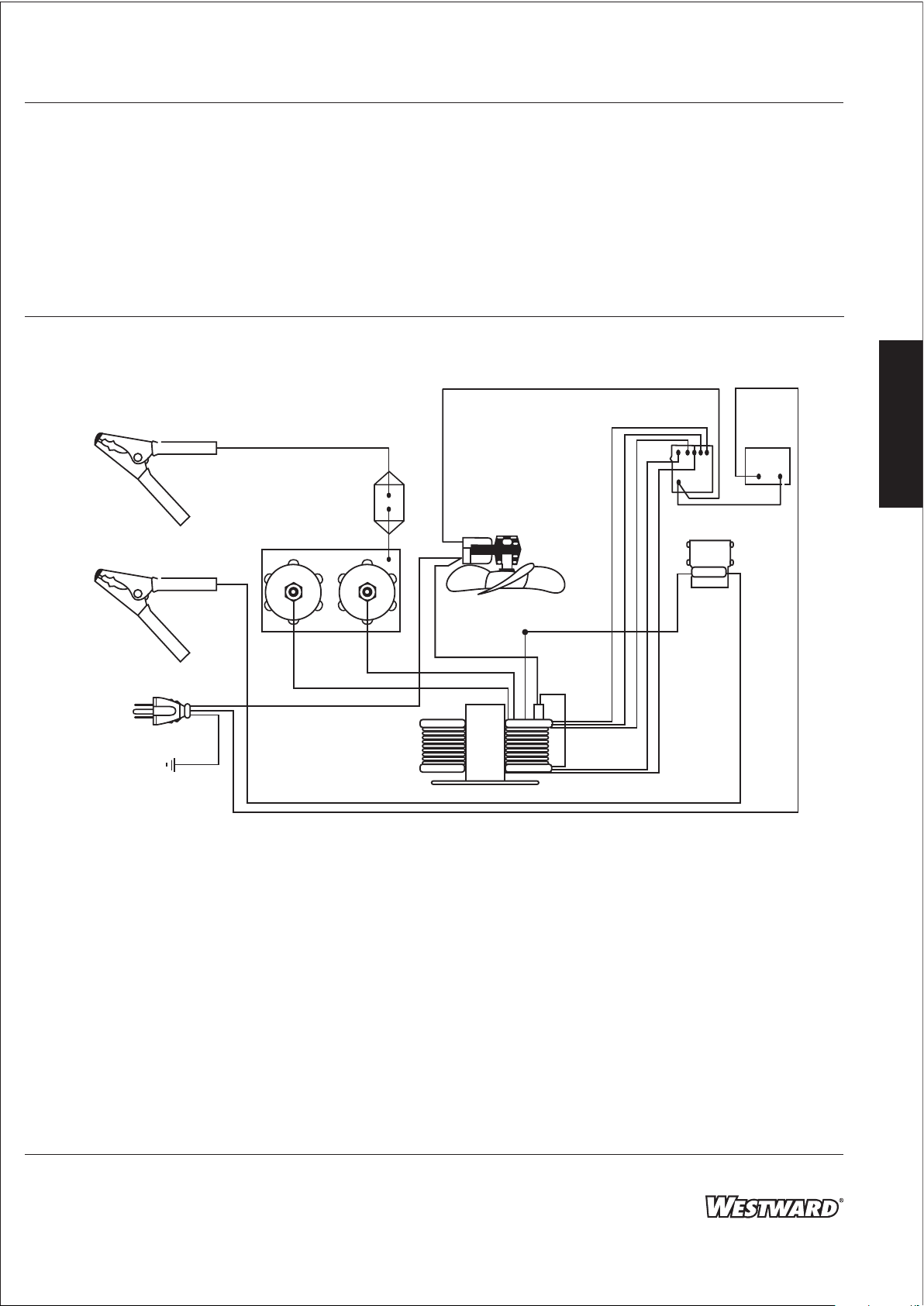
Figure 11 - Model 1JYT9A
Black
9
Page 10
Westward Operating Instructions and Parts Manual
®
Westward
Battery Chargers
1JYT9A, 1JYU1A, 1JYU2A and 1JYU3A
E
Wiring Diagrams (Continued)
N
G
L
I
Negative
Cable Assembly
(Black)
Black
Rate Selector
Switch
Timer
S
Black
Test
Switch
H
Circuit
Breaker
Positive
Cable Assembly
(Red)
Power
Cord
Green
White
Rectier
Fan
Center Tap
Black
Transformer
Thermal
Breaker
Black
Yellow
Black
Orange
Red
Blue
Ammeter
White
Voltmeter
w/circuit board
Black
Blue
Black
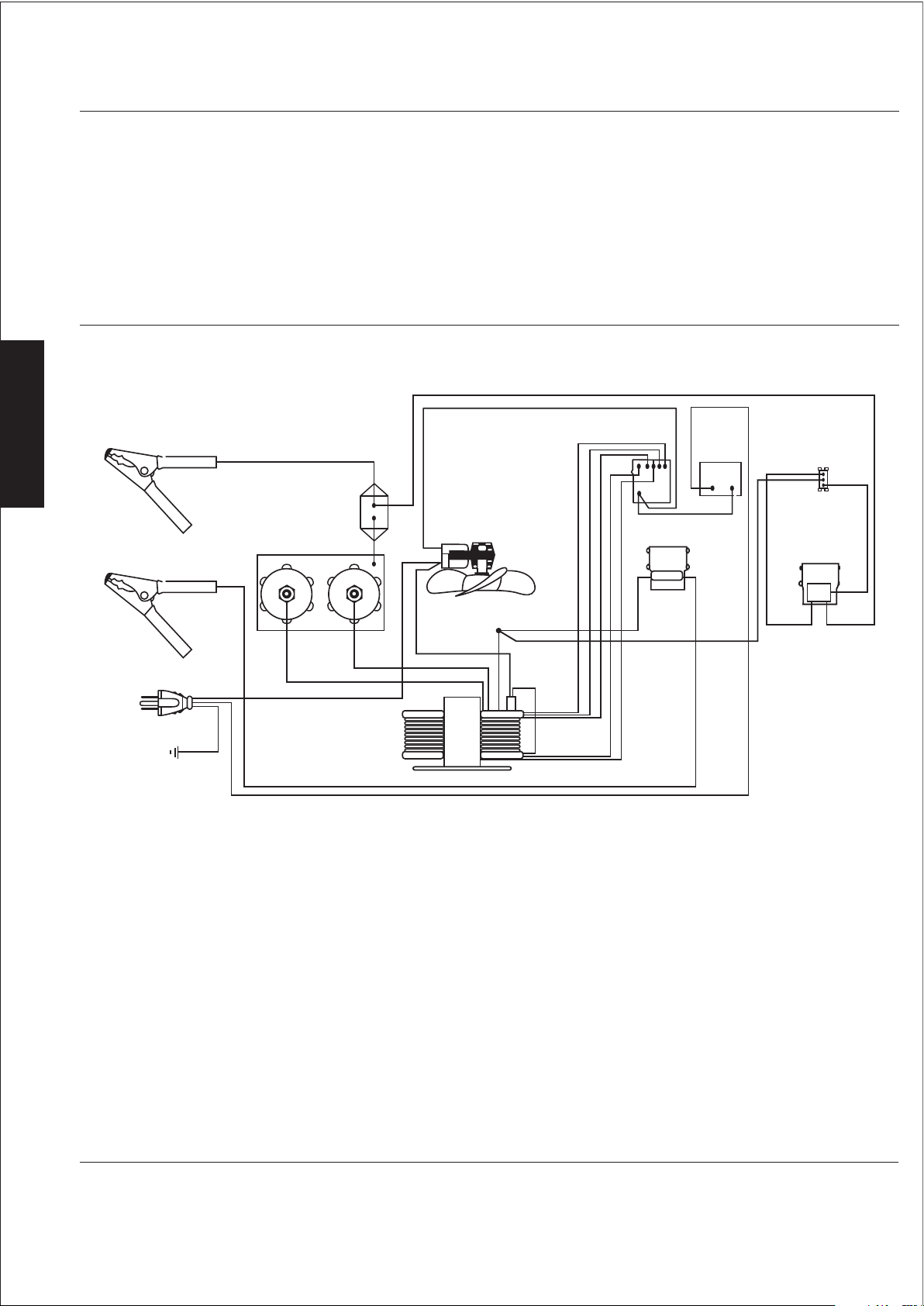
Figure 12 - Model 1JYU1A
10
10
Page 11
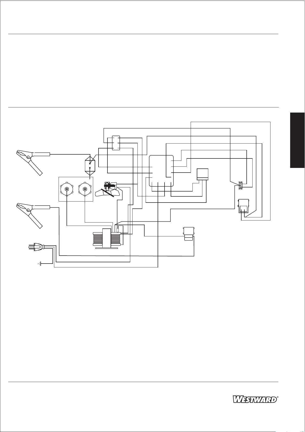
Westward Operating Instructions and Parts Manual
Models 1JYT9A, 1JYU1A, 1JYU2A and 1JYU3A
Wiring Diagrams (Continued)
Selector
Negative
Cable Assembly
(Black)
Positive
Cable Assembly
(Red)
Power Cord
Ground
Green
Circuit
Breaker
Rectier
Secondary Lead
White
Black
Switch
Secondary
Lead
Transformer
Fan
Red
Blue
Black
Black
White
Orange
Black
Thermal
Breaker
White
P
C
B
Center Tap
Red
Brown
Violet
White
Ammeter
Green
Yellow
Timer
White
Blue
Test
Switch
Voltmeter
Black
E
N
G
L
I
S
H
Black
Figure 13 - Model 1JYU2A
11
11
Page 12
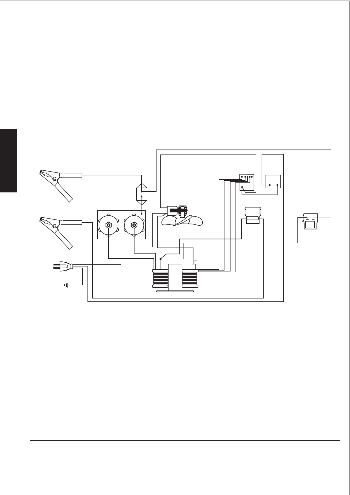
Westward Operating Instructions and Parts Manual
®
Westward
Battery Chargers
1JYT9A, 1JYU1A, 1JYU2A and 1JYU3A
E
Wiring Diagrams (Continued)
N
G
L
I
S
Negative
Cable Assembly
(Black)
Black
Rate Selector
Switch
Timer
Black
H
Circuit
Positive
Cable Assembly
(Red)
Power
Cord
Green
White
Rectier
Breaker
Fan
Center Tap
Black
Transformer
Thermal
Breaker
Yellow
Red
Blue
Black
Black
Ammeter
White
Voltmeter
w/circuit board
Black
Figure 14 - Model 1JYU3A
12
Page 13

Westward Operating Instructions and Parts Manual
Models 1JYT9A, 1JYU1A, 1JYU2A and 1JYU3A
Troubleshooting Chart
Charger inoperative
1. Power cord not plugged into outlet
2. Plug not making good connections in
outlet
3. No power at outlet
4. Defective power supply cord or plug
5. Open internal connection
6. Defective timer switch
7. Defective rectier, transformer,
circuit breaker, ammeter or switch
8. Circuit breaker has tripped
noitcA evitcerroC)s(esuaC elbissoPmotpmyS
1. Plug power cord into outlet
2. Inspect prongs of plug and straighten
if necessary. Replace outlet receptacle
if defective
3. Check supply fuses or circuit breaker.
If necessary, replace or reset
4. Check electrical continuity of cord
and plug. Replace if defective
5. Inspect all internal electrical
connections. Reconnect or tighten
any that are loose
6. Replace defective timer
7. Replace defective part
8. Set timer to OFF. Wait a few minutes
for circuit breaker to automatically
reset. Check cause of excessive
current and eliminate it
E
N
G
L
I
S
H
9. Defective cable or clamp
Charger will not charge in one or more
of the switch settings
Charger operates properly, but does
not return to OFF after timer is set
Charger operates, but charging circuit
won't turn OFF when timer is in OFF
position
IMPORTANT: Servicing must be performed by qualied service personnel.
Defective selector switch
Defective timer switch
Defective timer switch
13
9. Check continuity of each cable and
clamp. Replace if defective
Replace switch
Replace timer
Replace timer
Page 14
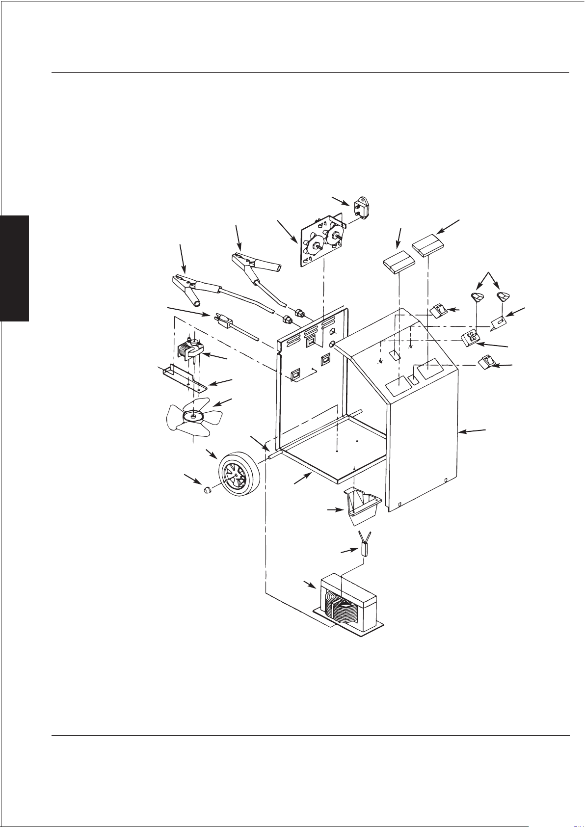
Westward Operating Instructions and Parts Manual
For Repair Parts, call 1-800-323-0620
24 hours a day – 365 days a year
Please provide following information:
-Model number
-Serial number (if any)
-Part description and number as shown in parts list
Address parts correspondence to:
Grainger Parts Operations
P.O.Box 3074
1657 Shermer Road
Northbrock, IL 60065-3074 U.S.A.
1JYT9A, 1JYU1A, 1JYU2A and 1JYU3A
12
10
E
N
9
11
13
14
G
L
16
I
S
H
8
15
17
18
7
19
6
5
4
20
3
2
1
Figure 15 – Repair Parts Illustration for Battery Chargers
21
22
23
14
Page 15
Westward Operating Instructions and Parts Manual
Repair Parts List for Battery Chargers
Servicing should be performed by qualied service personnel only.
Performed by qualied service personnel.
Replacement Parts List for models 1JYT9A, 1JYT1A, 1JYU2A, 1JYU3A
1JYT9A, 1JYU1A, 1JYU2A and 1JYU3A
Reference
9 “-” Negative Clamp with Cable and Strain Relief TT249261666G
10 “+” Positive Clamp with Cable and Strain Relief TT249260666G
“+” Positive and Negative Clamps with Grips TT249066666G
G000332145TTylnO feileR niartS”+,-“
13 Voltmeter/Test Meter for 1JYU1A and 1JYU2A TT246134666G
NOTE: No voltmeter on 1JYT9A.
14 Ammeter for 1JYT9A & 1JYU1A & 1JYU3A TT247133666G
G666773642TTylnO 2AUYJ1 rof hctiwS51
17 Rotary Switch for 1JYT9A & 1JYU1A & 1JYU3A TT246408666G
G666408568TTylnO 2AUYJ1 rof ylbmessA BCP71
∆ 1G050606044TTlenaP thgiR
∆ 1G050706044TTlenaP tfeL
∆ 1G666243244TTeldnaH
∆ 1G666620213TTredloH pmalC
ytitnauQrebmuN traPnoitpircseDrebmuN
1G050395044TTesaB1
1G666310860TTsbuH )2(2
1G666940314TTsbuH )2( dna sleehW )2(3
1G666340314TT)2( sbuH htiw elxA4
1G666410613TTedalB naF5
1G666095214TTtekcarB gnitnuoM naF6
1G666140612TTrotoM naF7
1G666213842TTfeileR niartS htiw droC rewoP8
1
1
1
1
1G666286568TTylbmessA reifitceR11
1G666904642TTrekaerB tiucriC21
1
1G666531642TTylnO 3AUYJ1 rof retemtloV31
1G666421742TTylnO 2AUYJ1 rof retemmA41
1
1
1G1666140642TTb (Timer) onK lortnoC61
1G666261042TT Control Knob (Rate Selector)61
1
1G666273642TTylnO 2AUYJ1 rof remiT81
1G666372642TT3AUYJ1& 1AUYJ & 9ATYJ1 rof remiT81
1G666732642TT2AUYJ1 & 1AUYJ1 rof )tseT(hctiwS91
1G666385044TT9ATYJ1 rof lenaP tnorF02
1G666185044TT1AUYJ1 rof lenaP tnorF02
1G666485044TT2AUYJ1 rof lenaP tnorF02
1G666285044TT3AUYJ1 rof lenaP tnorF02
1G666760213TT)erawdrah htiw( tooF tnorF12
1G666014642TTrekaerB lamrehT22
1G888838568TT9ATYJ1 rof remrofsnarT32
1G888538568TT2AUYJ1 & 1AUYJ1 rof remrofsnarT32
1G888118568TT3AUYJ1 rof remrofsnarT32
E
N
G
L
I
S
H
(∆) Not Shown. (+) Included with reference number 8. (-) Included with reference numbers 9 and 10.
15
Page 16

Wesrward Operating Instructions and Parts Manual
®
Westward
E
N
G
L
I
S
H
LIMITED WARRANTY
WESTWARD ONE-YEAR LIMITED WARRANTY. Westward
Electric Mfg. Co. (Westward) to the original user against defects in workmanship or materials under normal use for one year
after date of purchase. Any part which is determined to be defective in material or workmanship and returned to an
authorized service location, as Westward designates, shipping costs prepaid, will be, as the exclusive remedy, repaired or
replaced at Westward’s option. For limited warranty claim procedures, see PROMPT DISPOSITION below. This limited warranty
gives purchasers specic legal rights which vary from jurisdiction to jurisdiction.
LIMITATION OF LIABILITY. To the extent allowable under applicable law, Westward’s liability for consequential and incidental
damages is expressly disclaimed. Westward’s liability in all events is limited to and shall not exceed the purchase price paid.
WARRANTY DISCLAIMER. Westward has made a diligent eort to provide product information and illustrate the products in
this literature accurately; however, such information and illustrations are for the sole purpose of identication, and do not
express or imply a warranty that the products are MERCHANTABLE, or FIT FOR A PARTICULAR PURPOSE, or that the products
will necessarily conform to the illustrations or descriptions. Except as provided below, no warranty or armation of fact,
expressed or implied, other than as stated in the “LIMITED WARRANTY” above is made or authorized by Westward.
PRODUCT SUITABILITY. Many jurisdictions have codes and regulations governing sales, construction, installation, and/or use
of products for certain purposes, which may vary from those in neighboring areas. While Westward attempts to assure that its
products comply with such codes, it cannot guarantee compliance, and cannot be responsible for how the product is installed
or used. Before purchase and use of a product, review the product applications, and all applicable national and local codes
and regulations, and be sure that the product, installation, and use will comply with them.
Certain aspects of disclaimers are not applicable to consumer products; e.g., (a) some jurisdictions do not allow the exclusion
or limitation of incidental or consequential damages, so the above limitation or exclusion may not apply to you; (b) also, some
jurisdictions do not allow a limitation on how long an implied warranty lasts, consequentially the above limitation may not
apply to you; and (c) by law, during the period of this Limited Warranty, any implied warranties of implied merchantability or
tness for a particular purpose applicable to consumer products purchased by consumers, may not be excluded or otherwise
disclaimed.
PROMPT DISPOSITION. Westward will make a good faith eort for prompt correction or other adjustment with respect to
any product which proves to be defective within limited warranty. For any product believed to be defective within limited
warranty, rst write or call dealer from whom the product was purchased. Dealer will give additional directions. If unable to
resolve satisfactorily, write to Westward at address below, giving dealer’s name, address, date, and number of dealer’s invoice,
and describing the nature of the defect. Title and risk of loss pass to buyer on delivery to common carrier. If product was
damaged in transit to you, le claim with carrier.
Battery Chargers
®
Battery Chargers covered in this manual are warranted by Westward
1JYT9A, 1JYU1A, 1JYU2A and 1JYU3A
Manufactured for Grainger International, Inc.
100 Grainger Pkwy., Lake Forest IL 60045 U.S.A.
 Loading...