

Page 1

MX-400TS User Guide
Software revision 1.0.8
West Pond Enterprises, LLC
12/30/2016
Page 2

Contents
Revision History ............................................................................................................................................ 3
Related documentation ................................................................................................................................ 3
Terms and terminology ................................................................................................................................. 3
MX-400TS ...................................................................................................................................................... 4
MX-400TS Option Modules ....................................................................................................................... 4
MX-400TS Software .................................................................................................................................. 4
Setting up the system ................................................................................................................................... 5
Unpacking the unit .................................................................................................................................... 5
Installing in the rack .................................................................................................................................. 5
Making the connections ............................................................................................................................ 5
Power On .................................................................................................................................................. 5
Configuring the system ................................................................................................................................. 6
Front panel ................................................................................................................................................ 6
Accessing the WebUI ................................................................................................................................ 6
Getting familiar with the MX-400 ................................................................................................................. 7
Overview ................................................................................................................................................... 7
Sources ...................................................................................................................................................... 8
Network Sources ................................................................................................................................... 8
ASI ......................................................................................................................................................... 8
Video Server .......................................................................................................................................... 8
Outputs ..................................................................................................................................................... 9
UDP/RTP ................................................................................................................................................ 9
MDx00 ................................................................................................................................................. 10
ASI ....................................................................................................................................................... 10
Program Mapping ............................................................................................................................... 10
System ..................................................................................................................................................... 11
Settings ................................................................................................................................................ 11
Accounts .............................................................................................................................................. 11
Log ....................................................................................................................................................... 11
Info ...................................................................................................................................................... 11
Tools .................................................................................................................................................... 11
Confidential Page 1
Page 3

Confidential Page 2
Page 4

Revision History
Date
Version
By
Description
12/1/2016
1.0.16
sdh
Update to 1.0.8
12/30/2016
1.0.18
sdh
Cleared out ST stuff
Date
Version
By
Description
NA
1.15.1
sdh
User Guide, FlexStream MX-GS200, MD-100, RX-WP100
TS
MPEG2 Transport Stream
MPTS
Multi-program Transport Stream
Sources
Devices or software that generate MX-400 multiplexor Inputs
Inputs
TS traffic entering the multiplexor
Outputs
TS traffic exiting the multiplexor
Targets
Output devices receiving TS traffic from the multiplexor
Related documentation
Terms and terminology
Note: “MX-400” and “MX-400TS” are uses interchangeably in this document.
Confidential Page 3
Page 5
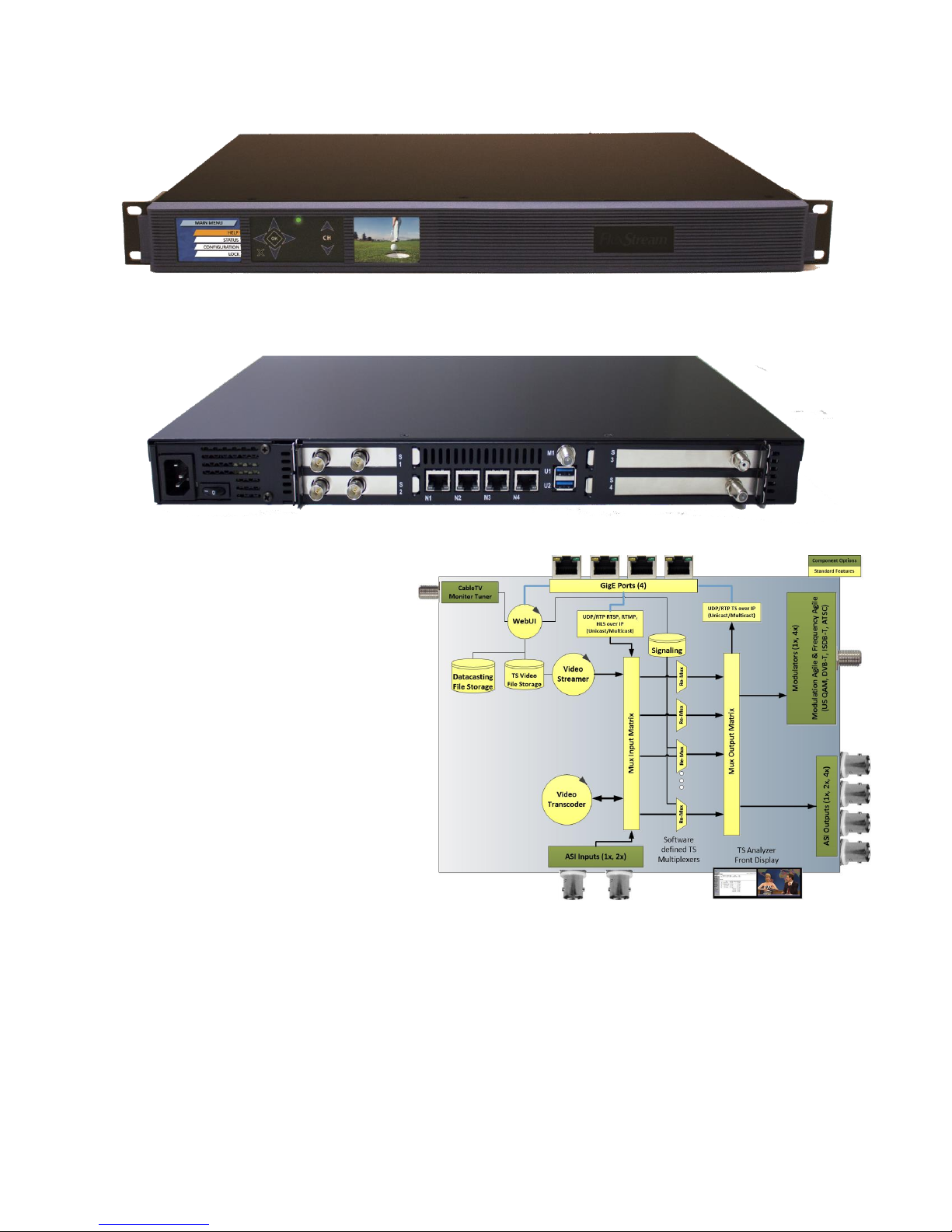
MX-400TS
Thank you for purchasing the MX-400TS
professional multi-stream multiplexer
system. This product was designed for
professionals who need a tightly
integrated TS multiplexer for channel
picking, program conversion, edge
modulation, any other professional TS
conversion. This document should help
you get the MX-400TS up and running
quickly. For more information please
contact West Pond Enterprises sales or
support.
MX-400TS Option Modules
The MX-400TS multiplexor accepts TS sources from ASI and IP inputs and will output a TS to ASI, IP, and
Modulator target devices. The standard configuration is IP to IP. ASI inputs/outputs and modulators are
optional. Each 1U unit supports up to 8 modulated output channels and 4 ASI input/outputs.
MX-400TS Software
The MX-400TS software package is optimized for multiplexing and as such the MX-400 can process up to
800 mb/s of transport stream data. The maximum throughput is content dependent but there are no
software limits on the number of TS inputs or outputs supported. Special features include PSIP table
Confidential Page 4
Page 6

merging, automated multicast IPTV channel discovery, a user friendly Web based UI, and front panel
video monitoring for all mux inputs. Supported TS sources include an integrated video server (TS file
spooling), TSoIP video/IPTV, RTSP (i.e. security cameras), and ASI. The multiplexer output can deliver
transports streams over IP, integrated multi-standard RF modulators, and/or ASI. SMPTE 2022
(proMPEG) FEC is available on all IP inputs and outputs.
Setting up the system
Unpacking the unit
The MX-400TS is a tightly integrated solution. The box is supplied with a power cable, other cables may
be provided with optional modules.
Installing in the rack
The MX-400 is a standard 19” 1RU AV rack mounted (round hole) device. Air flow for cooling the
devices is moved from front to back and it can be used in slots adjacent to other devices. Mount the
device using 4 front panel screws, connect the power to the rear of the unit.
Making the connections
There are four Gigabit Ethernet ports on the back of the MX-400. These can be independently
configured to support four unique LANs. Configure at least one of them as a management LAN from
which you can access the MX-400 via a Web UI. Others may be used to send/receive IPTV streams,
access to cameras (RTSP), or access to other assets used by the MX-400.
While video source hot swap is supported, this would be a good time to connect up any ASI sources to
the option module connections at the rear of the unit.
If the modulator option is included there will be at least two F connectors. The F connector marked M1
is the monitor input. Connect this to your in-house cable RF, after any downstream multiplexors,
amplification, etc. Treat this input just as you would a TV. This input port will be used to detect unused
frequencies on the in-house cable TV network. Modulator outputs will be in the right hand option
module bay. To merge the MX-400 channels with existing in-house cable TV channels, connect the
output F connectors to an RF combiner or distribution network.
Power On
Power on the MX-400 using the switch at the rear of the unit near the power receptacle. The blue LED
located at the center of the front panel will light immediately. Soon after this the two quarter VGA
screens will be illuminated. These screens will provide system status, real time video monitoring, and
basic system configuration.
Confidential Page 5
Page 7
Configuring the system
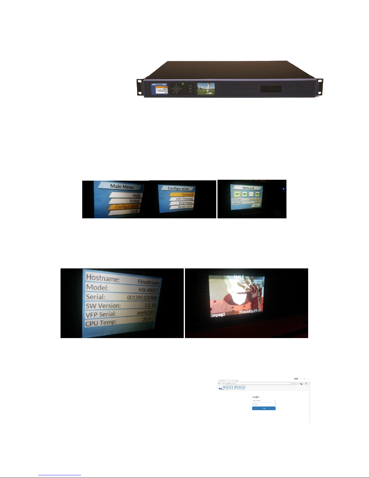
The MX-400 basic system
configuration is performed
using the front panel.
Software features are
configured using the MX-400
Web UI.
Front panel
Use the front panel of the MX-400 to configure each of the MX-400 network ports that are in use. Once
correctly configured, and connected to the network, the network icon on the front screen should be
outlined in green. If not, check the connections at the rear of the device and the configuration screen
for errors. One common error is mistaking N1 for N4, i.e. mentally reversing the logical order of the
network ports.
The front panel also provides access to status information (serial numbers, model numbers, system
state, etc.) and real time video monitoring (screen on the right). The video monitoring screen shows a
scaled replica of specified TS multiplexor input. Use the up channel and down channel buttons to cycle
through the video. This can be done at any time and has no impact on the state of the system.
Accessing the WebUI
Using a computer that shares a LAN with the MX-400, point a web browser to the IP address to which
the MX-400 was set. You will be prompted to login. Use the
administrator credentials
User: Administrator
Password: admin
Note: Firefox and Chrome preferred.
Confidential Page 6
Page 8

There are three built-in users. The passwords for these users can be set by the administrator.
Administrator: Used by installer to configure and manage the system. This user has access to all
controls and settings.
Operator: This user can view nearly all setting but can only controls those features that are not
mission critical. This typically involves the changing of content such as the content used in the
video server, and other items that do not impact the multiplexor, input and output configuration.
Monitor: Used by anyone who has an interest in the technology but should not be making any
configuration changes to the system.
Getting familiar with the MX-400
The West Pond manufacturing team will often preconfigure your device to provide a head start for your
particular application. This may include the installation of template presentations and creating input
and output streams. These are also part of the final test procedure. The IP addresses used for IP inputs
and outputs are likely inappropriate for your installation. In this section we will review how to make
small changes to these settings to get your system running as quickly as possible.
Overview
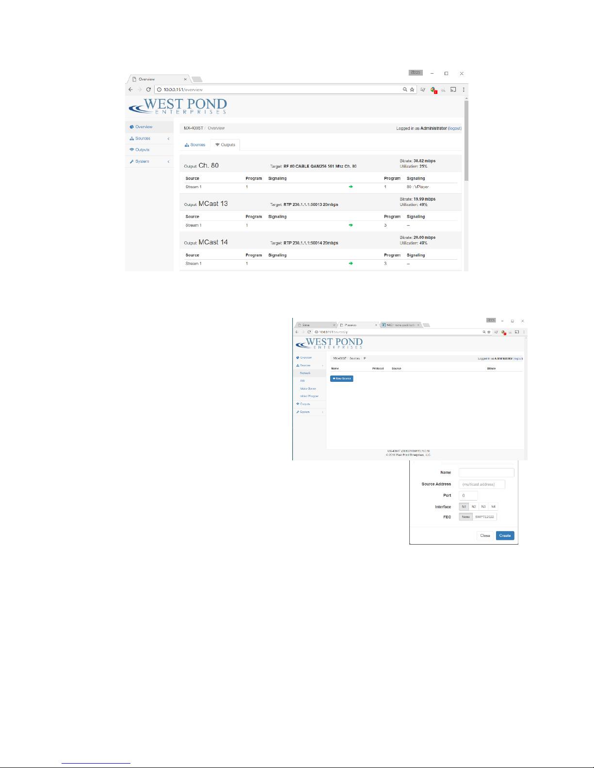
The top level page of the WebUI provides an overview of the MX-400 scalable multiplexor. The
multiplexor combines digital AV streams from a variety of sources into groups and transmits them with
the correct signaling and timing to the appropriate output. Outputs may have constraints, such as
bitrate and signaling, that must be configured to operate correctly. To preserve resources, inputs are
only processed if enabled. A mapping between inputs and outputs is shown in the overview menu of
the MX-400 WebUI. The sources (aka enabled inputs) are show on the left, outputs are shown on the
right. The sources tab groups these by the input while the output tab shows this mapping grouped by
destination (output). There is a variety of information on these pages that can be valuable when trying
to diagnose a problem. Error indicators are shown when a problem has been detected with a
particular input or output stream.
Confidential Page 7
Page 9
Sources
The Sources page shows how devices and IP streams are enabled as inputs to the multiplexor. Sources
may include
network streams such as IPTV or an RTSP
feed from a security camera
ASI expansion modules
the MX-400 internal video server
Network Sources
Network sources are shown on the
Sources>Network tab. To add a network source,
click “New Source”. Specify a friendly name for
the new source, this will be used on other pages of this webUI. Specify the
IP address (multicast if accepted), the port, and which interface the source
is available on. If the source supports SMPTE2022, then select this option.
When everything is complete, click create.
ASI
ASI inputs are automatically detected and populated if available. These entries may be edited to change
the name or enable/disable as necessary.
Video Server
The Video Server creates TS streams from files uploaded to the MX-400 storage. The MX-400 does not
transcode these files dynamically, as such the TS files used by the video sever must be compatible with
both the target receiver and transport output. For example, if you were to create a stream for a US
CableTV QAM modulated output, you need to ensure that the encoding is MPEG2 (not h.264) so that it
is compatible with that standard and can be displayed by TVs on that network. West Pond provides a
transcoding web service, FlexDM, which simplifies the process of creating the appropriate files. For
Confidential Page 8
Page 10
more information on this service contact West Pond sales. Additional information on how to use the
Video Server as an input source, please see the MX-GS200 user documentation.
http://www.westpond.com/support/Mx-GS200-UsersGuide.pdf
Outputs
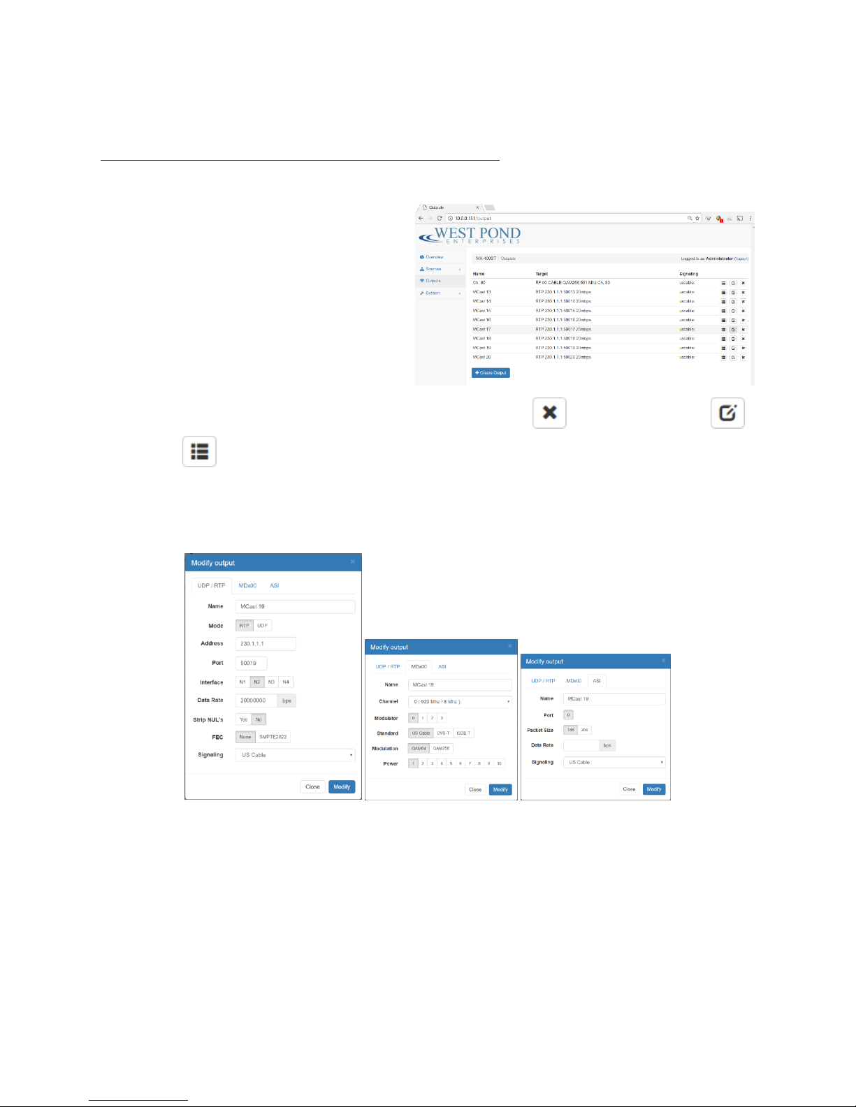
An Output is the output feed of the multiplexor.
As this is a software multiplexor, there is no
specified limit to the number of outputs. From
a practical perspective, it’s best to limit the
bandwidth consumed by the sum total of all
outputs to less than 500 mb/s. The multiplexor
outputs are MPEG2 transport streams. Each
MPEG TS output must be specified and is shown
on this page. New outputs are created by
clicking on the “Create Output” icon. Existing outputs can be deleted , modified (properties) ,
and mapped through the multiplexor (program mapping). The “create” and “modify” dialog boxes
are very similar. As shown below, these dialog boxes have a tab for each output type available. The
dialog box configures a single output, so the output type (tab) is selected first. The tab that is visible
when Save is clicked will be used. Data on other tabs may be lost.
UDP/RTP
If creating a traditional IPTV output, select and configure the UDP/RTP tab. UDP is raw UDP. The RTP
protocol, which is also transmitted using UDP, is more robust because the packets are numbered.
Additional robustness can be added using SMPTE2022 FEC, but this is only beneficial if the receiving
device can utilize the FEC data. The IP addresses and port fields are self-explanatory. Multicast
addresses are supported. Specify the interface you wish to bind this output to (N1, N2, N3 or N4). If you
aren’t sure of the routing, check the “System>Settings” page of this WebUI. The Data Rate used must be
sufficient to contain the multiplex transport that is being assigned. If insufficient, clipping will occur and
Confidential Page 9
Page 11
an error will be shown on the Overview page. Null stripping reduces the network traffic and is
recommended for non CBR applications. MPEG transport streams require signaling that is compatible
with the transport and targeting receiving devices. For example, if the IP output is feeding an edge QAM
modulator for the US market, select US Cable for signaling.
MDx00
This tab is for configuring modulator outputs. The modulator hardware is automatically detected and
appropriately populates the “Modulator” list (0,1,2,3) of this dialog box. All modulators are expected to
transmit over the same cable network, as such it is not necessary to identify how a modulator maps to a
particular F connector. Select the Channel
from the list. It’s best to be sure that the
channel selected is not in use. If the
Channel/Frequency you wish to use is not on
the list, you may need a new channel map.
Contact West Pond support if this is required.
Select the Modulator, the modulation
standard, and the modulation type. The
power level should be set to 5. Attenuators or
amplifiers should be used to achieve optimal
power within the cable distribution network.
ASI
This tab is only visible when ASI output hardware is available. To configure the ASI output, select the ASI
tab, provide a name, select the port number, specify the appropriate packet size, data rate and
signaling.
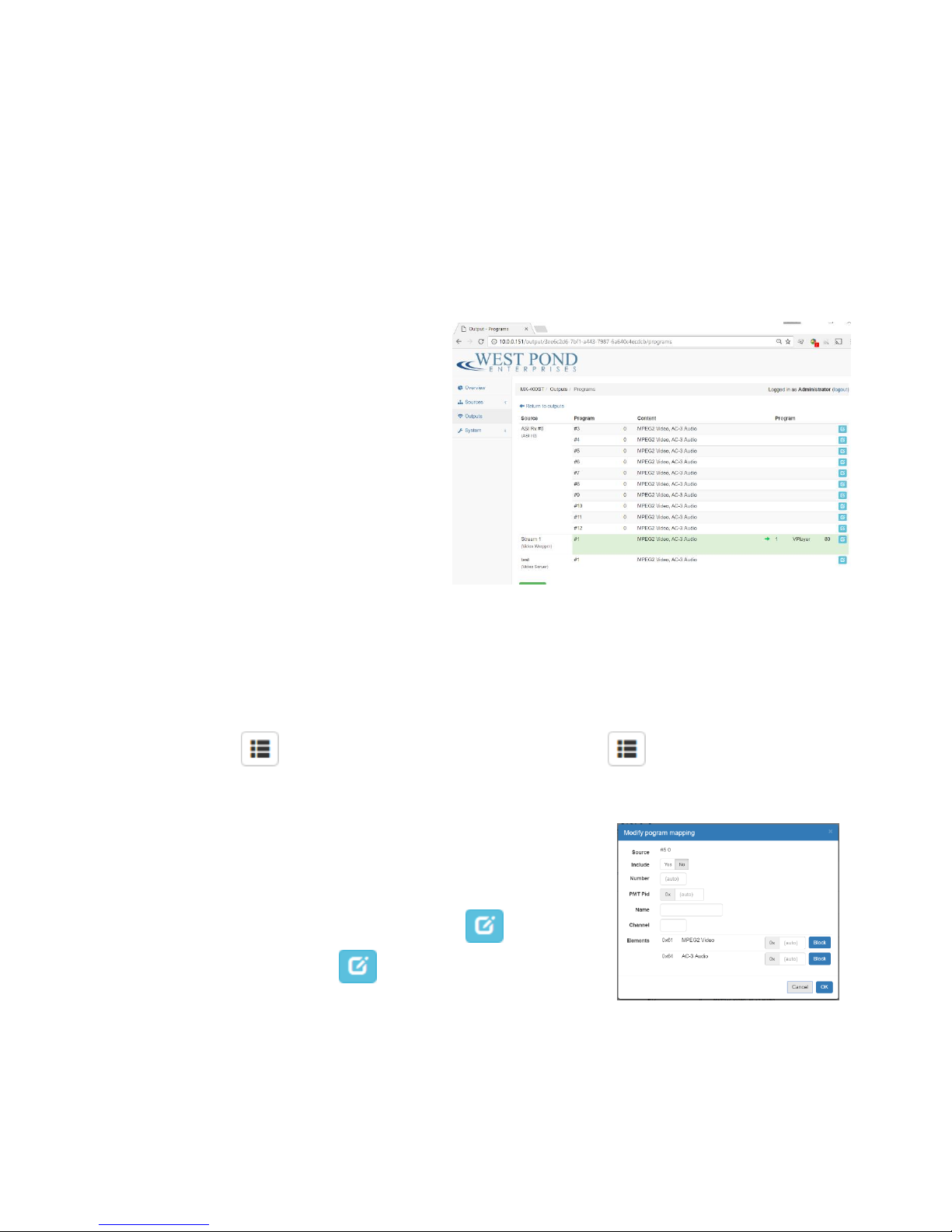
Program Mapping
Program Mapping is the heart of the multiplexor. Clicking on the icon for a specific output
will switch the Outputs page to a program mapping view for that output. Mapping an input to an output
can be done at the program level, or at the PID level. If you are not intimately familiar with transport
stream anatomy, stick with the program level and use the default
setting whenever they are provided.
Once in the Program Mapping view, all of the available multiplexor
sources are listed on the left, each with a mapping icon to the
right. Click on the mapping icon and edit the mapping
appropriately for each program you would like included in this output.
Be mindful of bandwidth limitations. If you oversubscribe the output, clipping will occur. If they occur,
these errors will be indicated on the Overview page of this UI. At times, since video encoding is a
variable bitrate, these errors will be intermittent. To be save, it’s best not to exceed 90% of the
available bandwidth. On the “Modify program mapping” dialog box, select “Yes” if you wish this source
Confidential Page 10
Page 12

to be included in the output. Give the program a name, this may be displayed on some TVs, and leave
the rest of the values as defaults. You can return to this dialog later and modify the channel number
(“Channel”) and program number (“Program”) to suit your needs. Click “OK” and repeat this for every
source you want included in this output. Note that source can be included in multiple outputs, there are
no restricts on how inputs can be mapped to outputs.
System
The System page is used for configuring and monitoring system level features of the MX-400 system.
Settings
This page provides a more comprehensive view into the network configuration of the MX-400 system.
Changes to these settings can be made via the WebUI and front panel.
Accounts
There are three preconfigured accounts for managing the MX-400. This page allows the administrator
to set the passwords for these three accounts.
Log
The Log page provide insight into status changes and errors that may occur at both the system and
software level in the MX-400. This is most useful when presentations are not functioning as expected.
Check this log for clues.
Info
Make, model, serial number, etc.
Tools
Software update and reboot.
Confidential Page 11
 Loading...