

Page 1
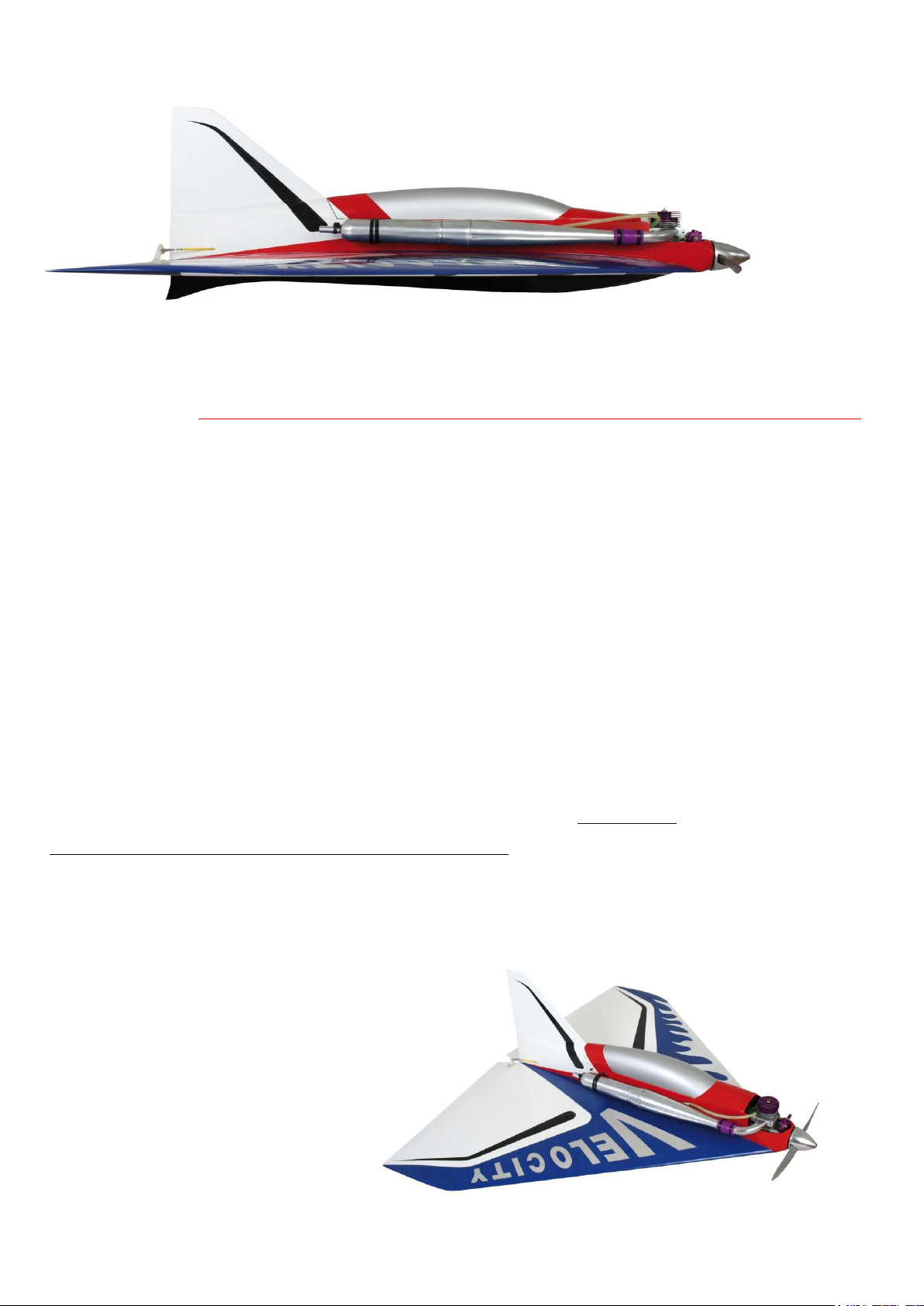
Electric or I/C
Velocity
This, the latest in the Weston UK range of hyper performance ARTF kits, has been
developed over a period of years to provide the ultimate flight performance.
PLEASE NOTE: THIS KIT HAS BEEN DESIGNED FOR EXPERIENCED MODELLERS.
READ THE INSTRUCTIONS FULLY BEFORE YOU START.
If you are unsure about any stage of assembly, please contact Weston UK direct.
I/C SETUP
WEST 52V1
GENESIS TUNED PIPE AND HEADER
PROSYNTH 2000 10% FUEL
ACCESSORY PACKS CONTAINING THE FOLLOWING:
COWLING
COOLING DUCTS x 4
ELECTRIC MOTOR BOX INCLUDING 4 BOLTS
ENGINE MOUNT INCLUDING BOLTS
INNER CONTROL SNAKES x 3
METAL CONTROL RODS x 6
METAL CLEVISES x 4
PLASTIC CLEVISES x 2
CONTROL HORNS x 2
2mm BOLTS x 6
2mm NUTS x 12
ENGINE BOLTS (4mm 1/8AF) x 4
CANOPY BOLTS (3 3/32AF) x 2
CLEVIS KEEPERS X2
CONTROL HORNS X 2
ELECTRIC SETUP
TENSHOCK 6P TS-0203022E/10T
CASTLE CREATION 100A ESC
5 CELL 4700MAH 30C MIN
PARTS LIST
FUSELAGE AND WING
TAIL FIN
SKID (DO NOT FIT)
FUEL TANK
ESC TRAY
BATTERY TRAY
Before starting please check all components. Additional items required for completion are radio gear,
motor, prop, tuned pipe/silencer, 2” spinner, cyano, epoxy resin, silicone tube, good quality tools and a
sharp blade!
Page 2
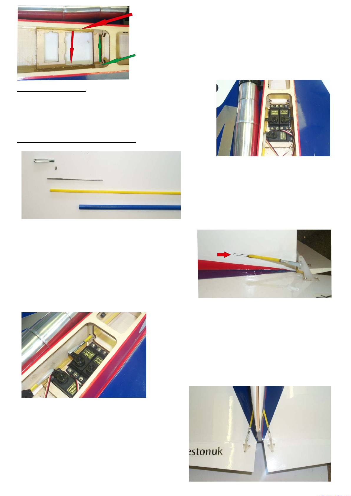
Before installing the servos we recommend
you bead 5 min epoxy on either side of the
servo tray to ensure security and to aid the
fixture of the throttle servo.
Please cut the outer snakes
so they just pass the frames.
If you do not do this it will
restrict full travel of the
control surface.
Servo installation
Install the servos in the tray as shown ( servo arms must be
forward most on the elevons). We recommend
high torque digital servos and for even more safety
metal geared.
Push rod and horn installation
Metal clevis
2mm lock nut
Metal push rod
Inner snake
Outer snake
(already in aircraft)
Note:- both the servos and control surfaces
should be in the neutral position. The inner
snake should be the correct length. The
metal push rod should be cut and de-burred.
Insert the metal push rod and do up
half way up the thread inside the inner
snake. When installed it should never come
outside the outer snake with the operation
of the control surface as per pics.
Insert the 2mm nut on the end of the thread
followed by the 2mm metal clevis. This
needs to be repeated at the other end. All
this is done in conjunction with the
positioning of the horn over the hinge point
of the control surface and at the correct angle
as per pic below. Secure the control horns in
place with the supplied bolts and nuts.
Metal pushrod should
be inside the outer snake
While making the control rods up
position the horns over the hinge line
and angle the control horns so they run
at the same angle as the snakes.
Please check once all complete to ensure
full and free movement.
Page 3
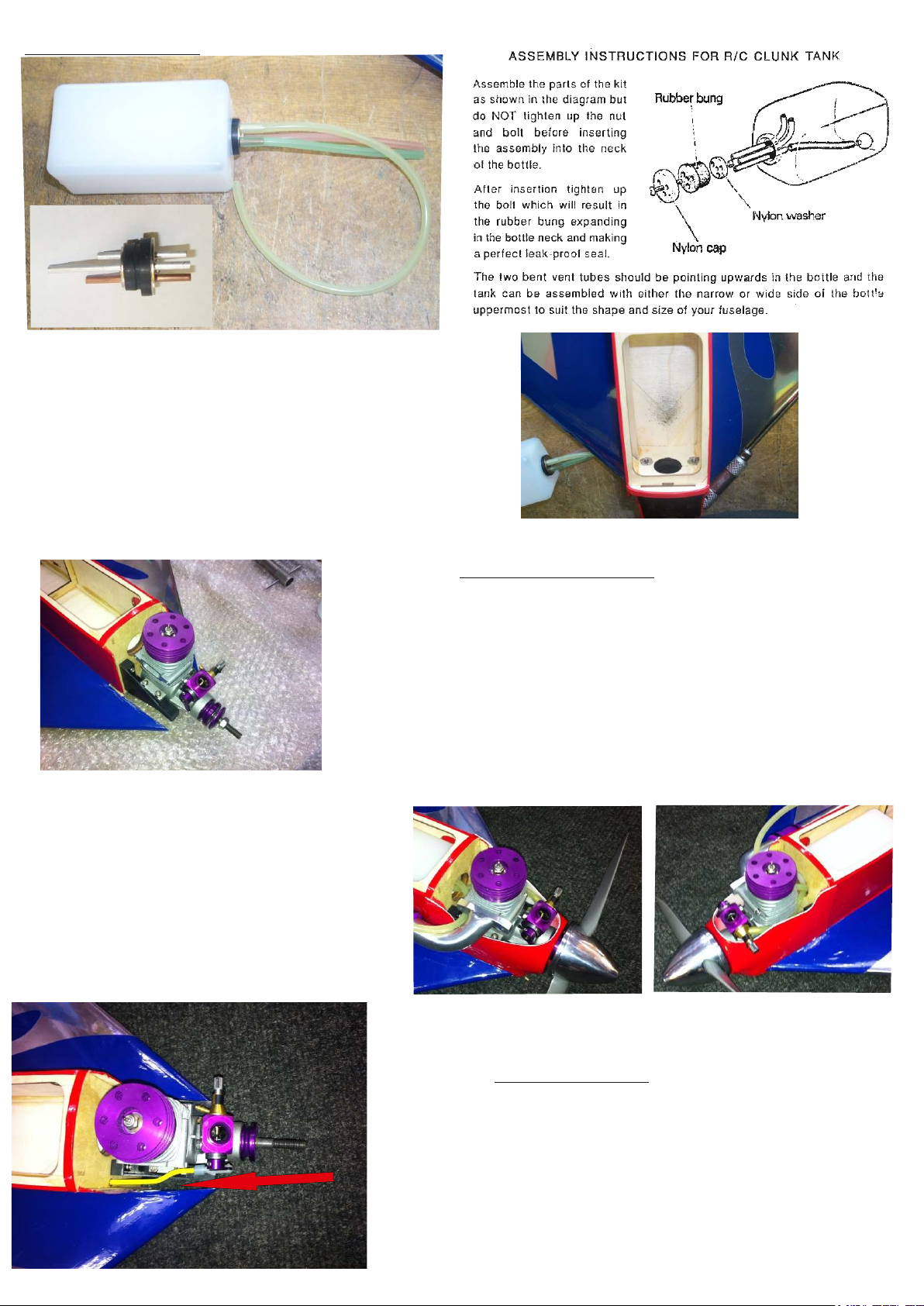
Tank installation
Install the tank into the bay and
pack with foam.
I/C INSTALLATION
Please install the engine mount with the supplied
bolts and washers using thread lock. Once secure
install your chosen engine (we recommend the
West 52V1) Using the deep core self tapping screws
secure in place. We recommend a small amount
of thick cyano on the thread of the self tappers to
lock in place. Ensure that the motor clears the
cowling ring when in place.
Cut cowling as required and secure
using the 4 supplied screws.
Engine installation
Throttle install
Install the inner snake as per the elevons and a
set is required so no binding is present. A plastic
clevis is to be used at the carb end to ensure no
metal to metal contact. Also use the other plastic
clevis for the servo end and when completed use
the clevis keepers (small piece of tubing)
to secure clevis closure.
Page 4
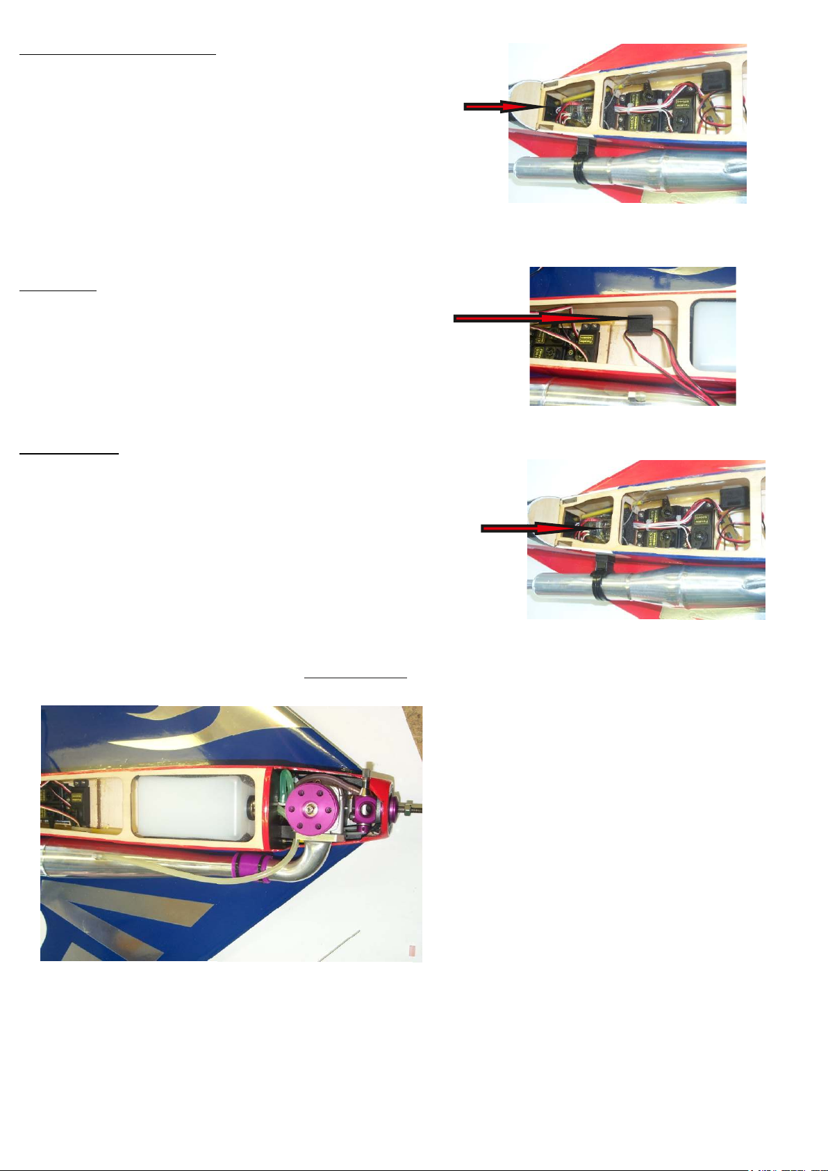
BATTERY MOUNTING
The battery is mounted on the balsa sheeting
behind the receiver tray at the rear of the fuselage
using double sided servo tape or foam to pack
in place. The battery should sit between the
two snakes ensuring it does not push
against the outer tubes to cause binding. We
recommend a 6v 2/3 GP pack which is available
from Weston UK.
SWITCH
Mount the switch in the side of the fuselage
on the opposite side of the engine exhaust
in front of the servo tray area.
RECEIVER
The receiver is placed in front of the battery
at the back of the fuselage ensuring you
restrain all leads and crystal before
wrapping the receiver in foam and
wedging in place.
Pipe install
Install the manifold and the tuned pipe which are
available from Weston UK as shown.
The best method of attachment for the manifold
to the engine is using 5min epoxy which acts as a
gasket and any residue left inside will burn off.
Page 5
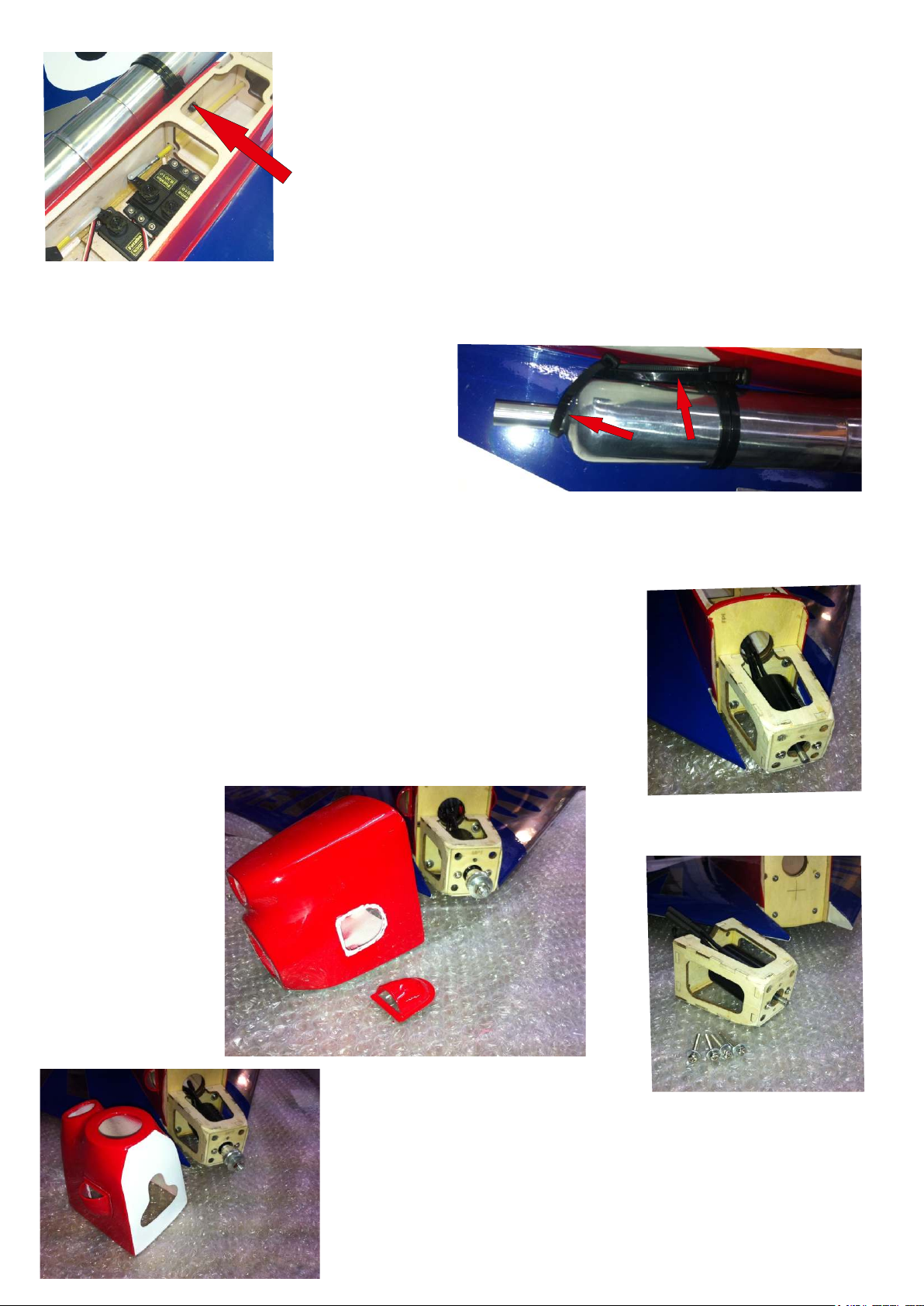
Using a silicone joiner which is available from
Weston UK join the tuned pipe to the manifold.
Mark the position of the tuned pipe on the mounting
plate at the rear giving yourself enough room to
insert the bolt for the canopy. When happy bolt the
airframe clamp available from Weston UK to the
fuselage and tie-wrap the tuned pipe to the clamp.
We recommend you use two tie-wraps
as per the picture to stop the pipe
coming off due to vibration and
high speed gas flow. Do not over
tighten as this will pull the pipe up
against the manifold and damage it.
Electric motor installation
Install your chosen electric motor
(we recommend the Tenshock TS-0203022E/10T
6 pole motor) in the motor box. Then install the
motor box on the fire wall using the supplied bolts
and washers with some thread lock. Pass the
cables through tank pipe hole and into the fuselage.
Mark up positions of side cheek cooling ducts
and cut holes as required ensuring you key the
surface of the area where the cooling ducts will be
fitted. Ensure the cooling ducts are not to low
to ensure clearance of the wing. We
recommend cutting an air out hole at the bottom
of the cowling as per pic.
Page 6
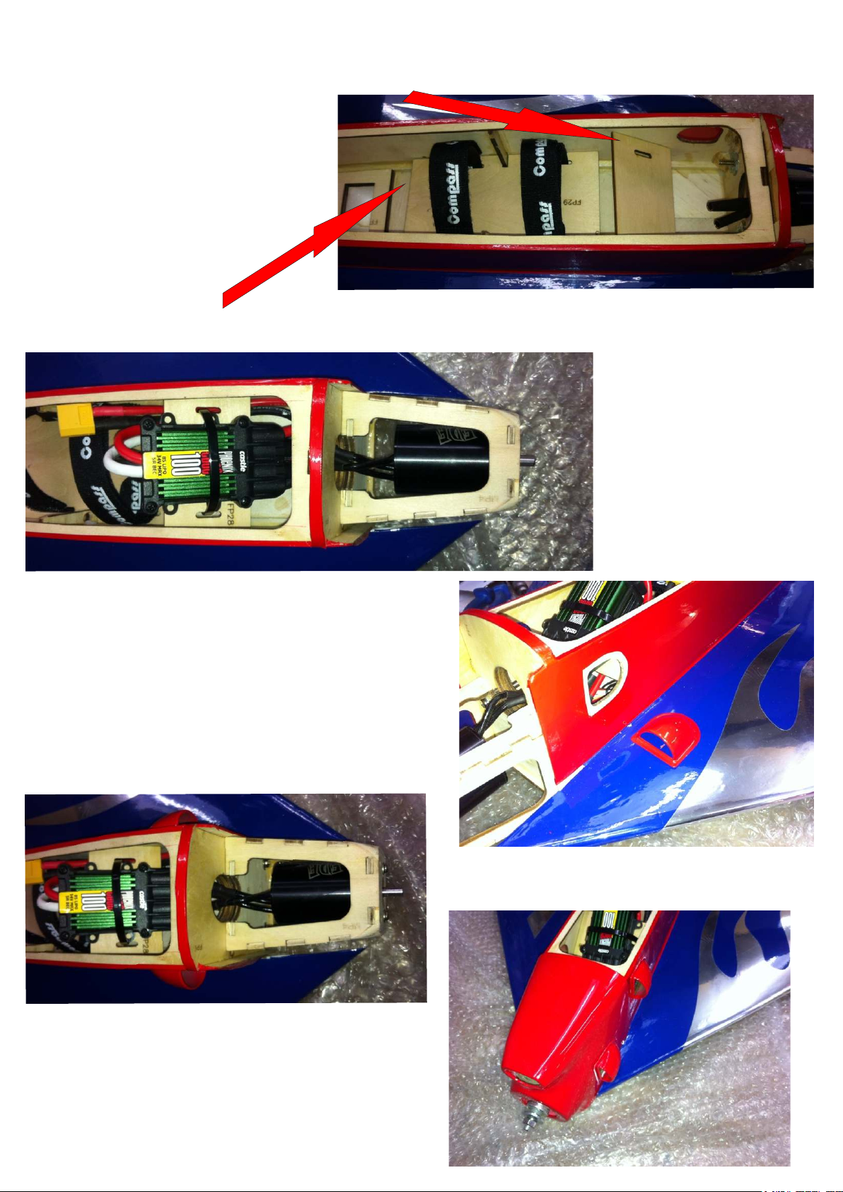
Install the esc tray with epoxy in tank bay ensuring the tray is at the correct
angle as to not prohibit the canopy fitment.
Install the battery tray with epoxy as per the picture. We recommend installing
the velcro straps before the tray is installed.
Install ESC to tray and
secure in place with a
tie-wrap
Cut the covering away from the cooling
holes and cut a small piece of covering
away from around the hole to ensure good
surface contact and bonding. When happy
glue in place the cooling ducts on both
sides.
When happy install the cowling
with the 4 supplied screws.
Page 7
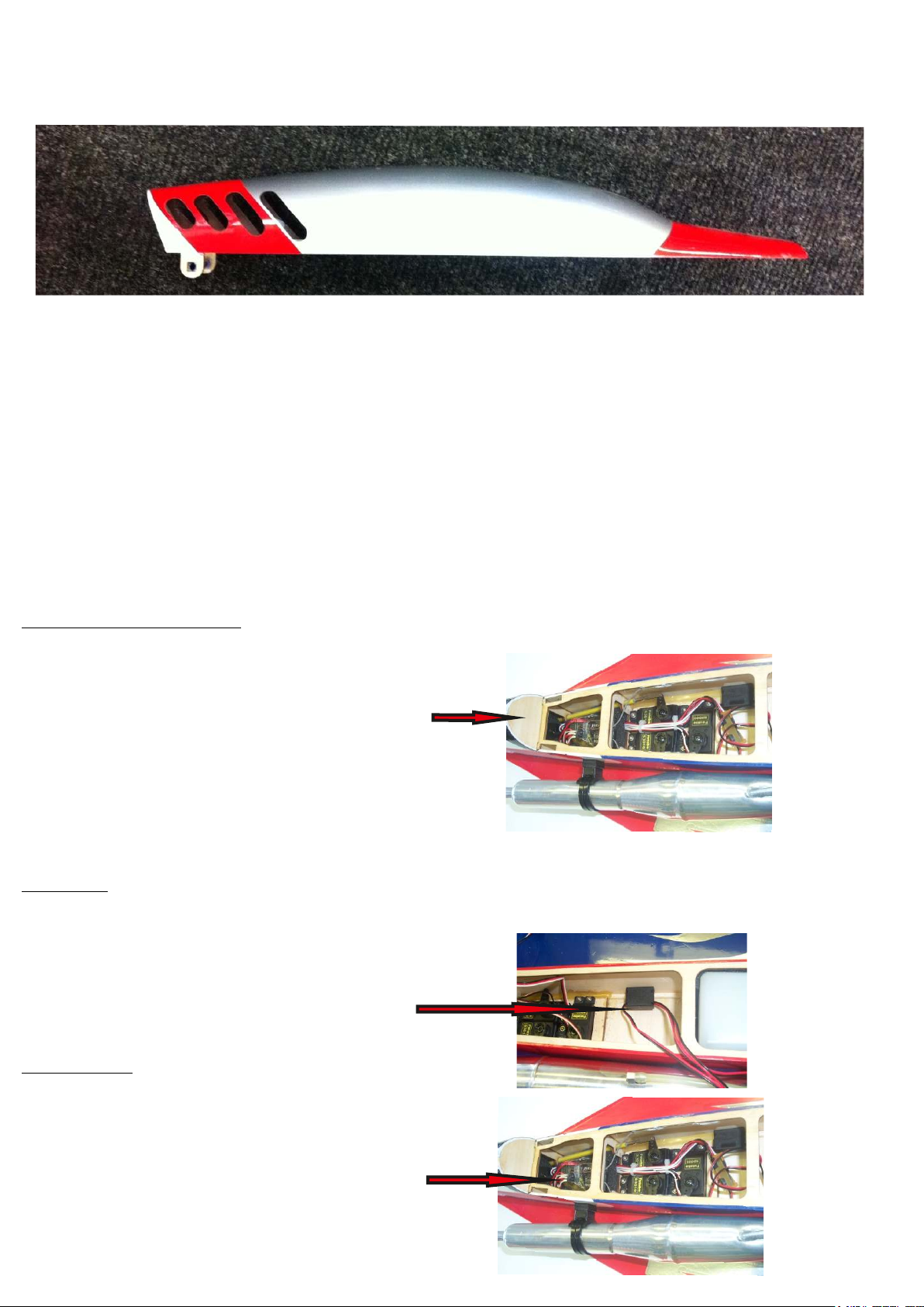
With a sanding drum cut hole as per picture
in back of canopy to allow air flow out of
the airframe.
Note :- cooling for electric is imperative and you must follow the instructions
explicitly. When flying this kind of electric set up you cannot run for long
durations as you will burn out your set up. 10-20 second blasts is what we
recommend with some gliding in between to allow set up to cool. SAFETY NOTE :
When first setting up your motor and esc please ensure the prop is NOT on
the motor.
SAFETY NOTE:- Even on a BEC ESC we recommend you install a flight Rx battery
in case of any ESC failure.
BATTERY MOUNTING
The battery is mounted on the balsa sheeting
behind the receiver tray at the rear of the fuselage
using double sided servo tape or foam to pack
in place. The battery should sit between the
two snakes ensuring it does not push
against the outer tubes to cause binding. We
recommend a 6v 2/3 GP pack which is available
from Weston UK.
SWITCH
Mount the switch in the side of the fuselage
on the opposite side of the engine exhaust
in front of the servo tray area.
RECEIVER
The receiver is placed in front of the battery
at the back of the fuselage ensuring you
restrain all leads and crystal before
wrapping the receiver in foam and
wedging in place.
Page 8

TAILFIN
Place tailfin in the slot. Using a knife carefully mark around the fin where the fuselage meets the
fin. Remove the fin from the slot and carefully cut away the covering ensuring that no balsa is
cut. Insert the fin into the slot and using some thin cyano or slow cyano or epoxy carefully glue
the fin into the slot.
LANDING SKID
Place the skid into position so that the back of the skid is flush with the rear of the fuselage.
Mark out the position of the skid and remove the film from the wing with a sharp knife ensuring
no balsa is cut. Once removed using slow cyano or epoxy glue, glue the skid into position.
(we don't recommend fitting it)
GENERAL INFORMATION
WARNING:- We recommend you seal all round the edges of the covering
with Tufkote to ensure no covering will lift during high speed flight.
Centre of gravity:- this should be 310mm- 320mm from the front nose ring of the fuselage.
MOVEMENTS - elevator up and down 15mm
- ailerons up and down 10mm
Measurements are taken from the widest part of the control surfaces.
The Velocity is very stable at high and low
speed manoeuvres. We suggest you have
someone to launch the model for the
first few flights until trimmed and you
have become familiar with the Velocity.
If fitted with the West Eurotech 52 V1 you
will soon have no problem in launching the
model on your own.
84 - 88, London Road,
Teynham,
Near Sittingbourne,
Kent. ME9 9QH.
England.
Tel: +44(0)1795 521030
Fax: +44(0)1795 522020
Vat Reg. No 217 2427 83
www.westonuk.co.uk
 Loading...