

Page 1
This is not a toy
Electric or I/C
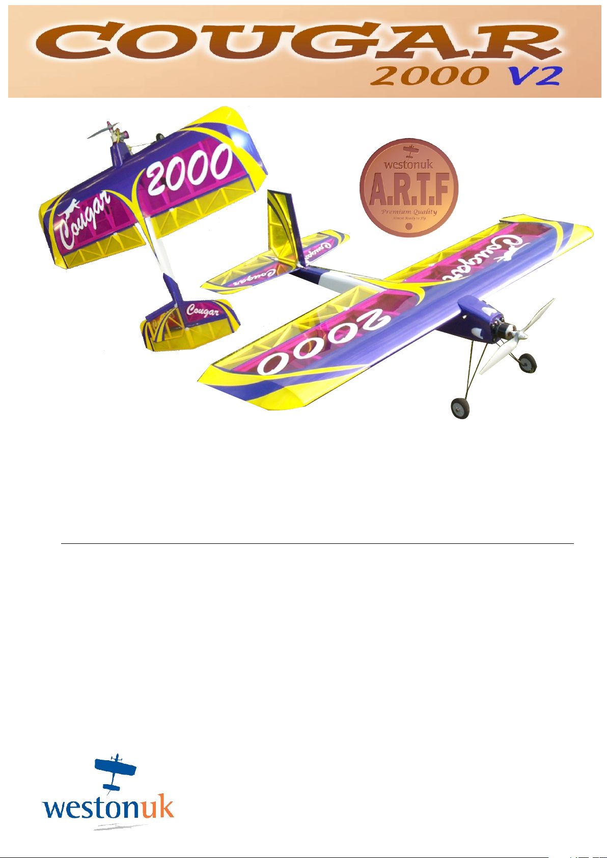
The Cougar 2000 is one of Weston UK`s high performance ARTF
kits designed to provide the ultimate in freestyle and 3D
performance. Flick the rates on and with the Cougar`s unsurpassable slow
speed characteristics it becomes the ideal trainer aircraft.
READ THE INSTRUCTIONS FULLY BEFORE COMMENCING
IF UNSURE ABOUT ANY STAGE OF ASSEMBLY PLEASE CONTACT WESTON UK
MATERIALS REQUIRED FOR COMPLETION
Motor (.36 size 2 stroke recommended motor West Eurotech 36TIR)
Prop (APC 11x4)
Electric motor West 770kv and 60A speed control, 4 cell 3350 lipo,13x6.5 APC prop
(up to 15 min flight duration)
Electric motor West 770kv and 60A speed control, 3 cell 2200 lipo, 14x7 APC prop
(up to 10 min flight times)
Cyano
Good quality tools and a very sharp blade.
WE RECOMMEND HITEC RADIO EQUIPMENT AS USED BY
THE WESTON UK DISPLAY TEAM.
Recommended servos:
Throttle HS 325 Elevator/Ailerons HS 625MG Rudder HS 645MG
84-88, LONDON ROAD
TEYNHAM,
NEAR SITTINGBOURNE
KENT. ME99QH
ENGLAND
Tel:+44(0)1795 521030
Fax:+44(0)1795 522020
www.westonuk.co.uk
Page 2
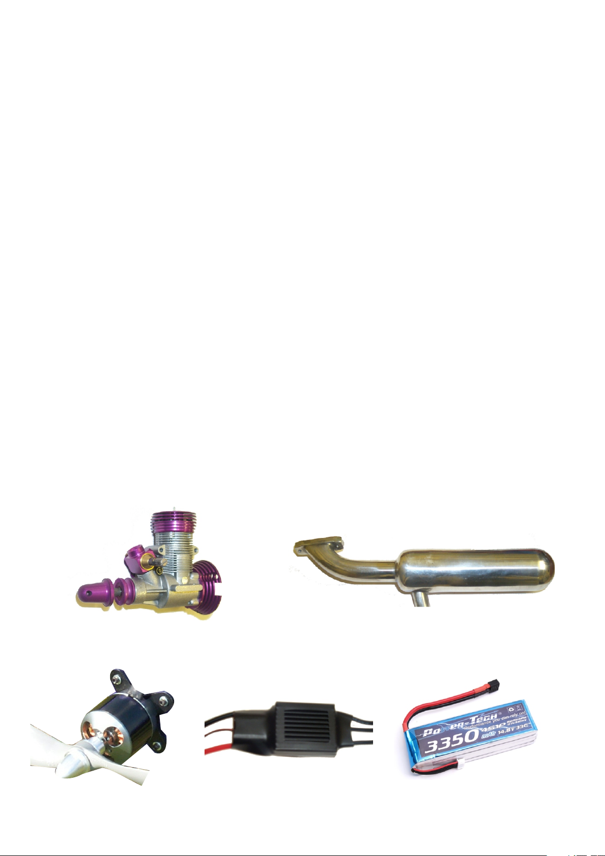
Designed specifically for the Cougar 2000 the West 36 TIR motor and pipe combination gives
more power than most 50 size engines. We recommend the West 36 because with the
enormous power advantage and minimal weight penalty of this motor (only 290g including motor
mount) the Cougar 2000 will perform every trick that it has been designed to do.
Not only will another power plant not perform so well but it will also weigh more which means
having to spread the weight further back in the airframe in order to achieve the correct C of G.
This then increases the moment arm effect giving a poorer performance, whereas the West 36
package will allow the weight of the radio accessories to be on the C of G giving ultimate
performance.
We recommend that if this is your first plane and you have not already joined a club that you do so
not only for the safety of yourself and others but for advice. Its always best to get a second opinion
if it is your first build and even if you're an expert, and ensure that you contact the BMFA to get your
insurance.
Parts list
Fuselage
Tailplane and elevator
Rudder and fin post
Wing
Ailerons x 2
Wheels x 2
Undercarriage
Tail skid
Engine mount
U/C securing plates x 4
U/C securing screws x 8
Wheel collets x 2
control horns x 5
control horn back plates x 3
wing dowels (carbon) x 2
elevator rod (carbon) x 1
elevator push rods x 2
aileron push rods x 2
throttle push rod
clevises x 7
swing keepers x 3
closed loop wire
clevis adjusters x 2
crimps x 4
Recommended motor West 36TIR and Genesis pipe.
(Which produces over 2.2BHP)
Recommended West 770KV motor and 60A controller, 4 cell 3350 lipo.
(Up to 15mins flying time)
Page 3
WING
AILERONS
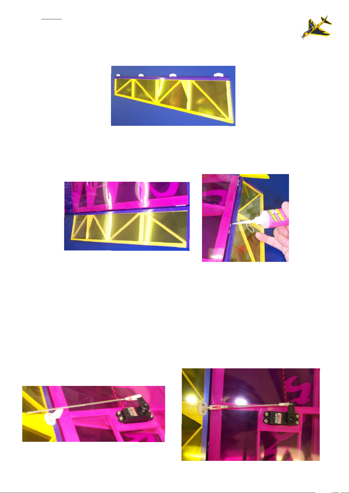
Each aileron has four hinge points pre-cut. Carefully insert the mylar hinges supplied in
the accessory pack into the ailerons ensuring that the long cut-out in the centre of the
mylar hinge runs parallel to the leading edge of the aileron.
Once in place lock these into position with a couple of drops of thin cyano top and
bottom. Ensure the pre-cut slits in the wing align with the mylar hinges in the aileron.
When you are happy insert the aileron into the wing so there are no gaps between the
wing and the aileron and there is no binding at the edge. Push the aileron down and apply
thin cyano to the hinges. Repeat procedure on the opposite side of the same aileron.
Repeat procedure on the other aileron.
AILERON SERVOS
Install a small draw wire through the wing section very carefully ensuring you do not
catch any ribs and draw the servo cable through the wing section to the exit point at the
centre of the wing. Repeat procedure for the other servo. Secure servos in place with the
servo arm forwardmost, take the two aileron pushrods supplied and attach the clevises to
the threaded ends. With your servo in the neutral position clip the pushrod onto the servo
arm. You can now use this to align the position of your aileron control horns on the
aileron over the strengthening points. Once the position has been found, ensuring the
clevis attachment point on the horn is positioned over the hinge line, secure into position
by drilling and bolting the control horn and backing plate together. Repeat procedure on
the other aileron. Disconnect the aileron pushrod clevis from the servo and connect to the
control horn. With the servo in the neutral position and the aileron in the neutral position,
connect th e control rod into the servo arm using the swing keeper. Repeat procedure on
the other rod.
Page 4
TAIL PLANE
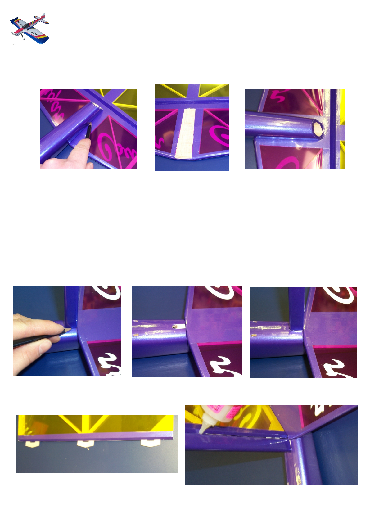
Position the tail plane on the fuselage ensuring that it is correctly aligned. When happy
mark out the joining points with a pen and remove the tail plane. Using a very sharp knife
remove the film ensuring that you do not cut into the wood. When happy glue the tail
plane to the fuselage with epoxy.
FIN
Insert the fin into the pre-drilled hole in the back of the fuselage and ensure it passes
through the fuselage and into its pre-drilled locator in the bottom of the fuselage. If this is
not correctly inserted into the fuselage the fin post will not be at the correct angle and
when the rudder is attached it may bind against the tail plane. Once in position mark out
the fin post point on the fuselage. Remove the film with a sharp knife making sure not to
cut into the wood. Reassemble the fin into the fuselage and glue into position. It is
advisable to run some glue down at the back of the fuselage internally to secure the
carbon rod into the lower part of the fuselage. Insert the mylar hinges into the rudder pre
cut slits as per the ailerons. Insert the rudder into the post and ensure there is no binding
on the tail plane. When happy secure into position with thin cyano.
Page 5
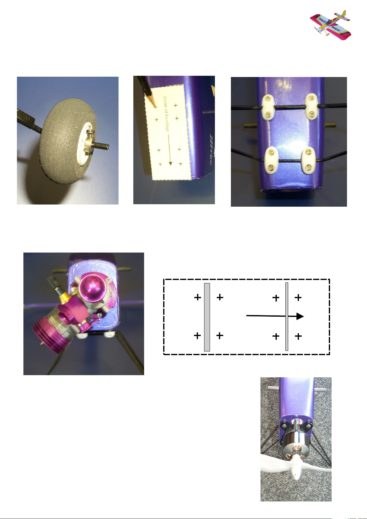
UNDERCARRIAGE
Secure the wheels to the u/c using the wheel collets supplied. Then using the template
provided mark the holes for the screws and attach the u/c to the front of the model on the
ply plate using the four plastic securing plates and the 10mm self-tapping screws. Make
sure when installing the undercarriage that the thin wire of the undercarriage is to the
front of the aircraft. Please be aware that the screws do exceed the thickness of the ply
plate so will need to be cut down so not to damage either the fuel tank or battery if
electric.
MOTOR
If using the recommended West 36TIR motor simply mount the motor directly to the
firewall using the bolts provided so that the head is at the 7 o`clock position. If using the
engine mount simply install this using the bolts provided and mount your chosen motor to
it so the head is at the 7 o’clock position.
Cougar u/c template
Front of Fuselage
Front of Fuselage
FAT WIRE
If you are installing the west 770 electric motor simply position the electric
motor mount in the centre of the fuel tank outlet hole. Then mark and drill the
mounting holes and using the bolts supplied with the electric motor install the
capture nuts. It will be necessary to remove one of the pre installed capture
nut for the west i/c engine. Before installing the motor it is necessary to drill
a small hole above the motor for the wires to enter the fuselage. Once complete
install the motor to the firewall.
THIN WIRE
Page 6
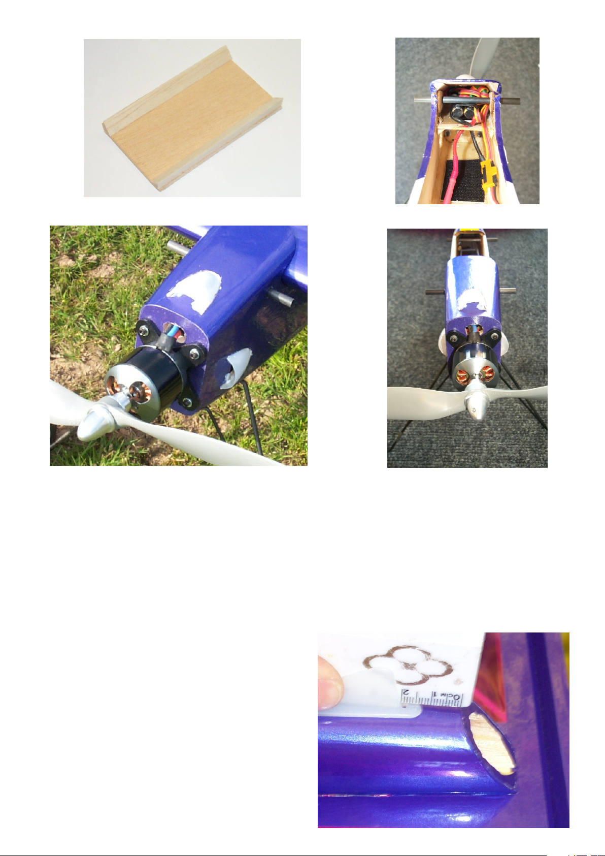
TAIL SKID
Fit the tail skid 20mm from the rear of the
fuselage using the 3 x 8mm self tapping screws.
Using the ply plate and triangle re-inforcing install the speed
control tray. Use the speed control to set how high the tray
can be as you need it to be as high as possible for the lipo
access. With the tray in position you can now mark out and
cut the holes for the cooling ducts. Make sure the two side
ones are below the speed control tray hight. Cut and glue
the cooling ducts into position and install the speed controller.
Run a smooth thin film of 5min epoxy along the bottom of the
fuselage and when dry attach some velcro to the bottom of
the fuselage for the attaching of the lipo.
Page 7
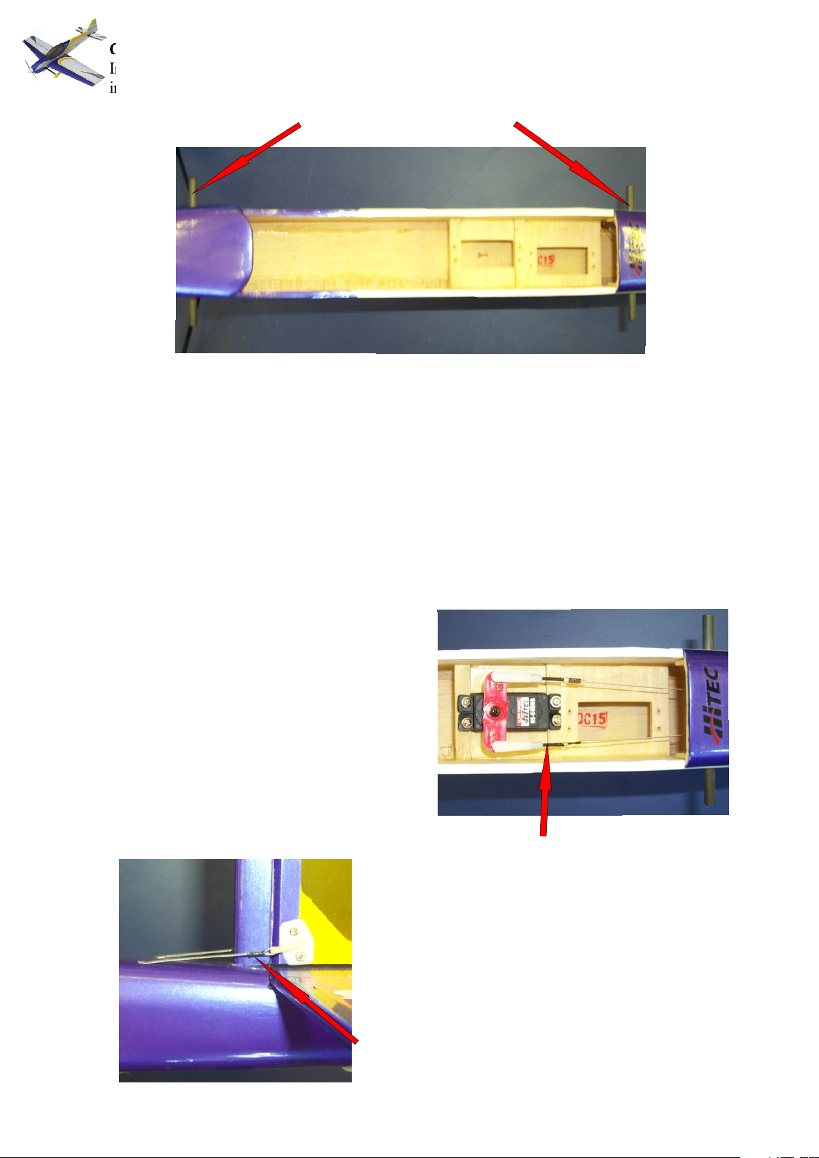
CARBON WING DOWELS
Install the 2 x carbon tubes into the pre-drilled fuselage at either side of the wing and glue
in place with thin cyano. Please note it will be necessary to shorten the rear carbon wing
dowel so as not to interfere with the aileron movement.
RUDDER SERVO
Install the rudder servo in the raised servo tray with the output arm forwardmost. The
rudder utilizes a closed loop system. Install the 2 x control horns onto the rudder over the
reinforced area ensuring the clevis attachment points are over the centre of the rudder
hinge line. Secure in place with the 2 x 15mm bolts and 2 x nuts ensuring that the horns
are at a slight angle so that the closed loop cables when attached are not at an awkward
angle. Ensure that your rudder servo is in the neutral position and pass the closed loop
wire through the fuselage from the rudder outlet point to the corresponding side of your
servo arm. Connect the cable at the rudder using the crimp only. Connect the cable at the
servo arm with the crimp, clevis adjuster and clevis. Ensure when doing so that the
rudder and servo are in the neutral position. Repeat procedure on the other control wire
ensuring you do not twist the wires around each other inside the fuselage.
Rudder servo installed with the output arm
forwardmost. With the closed loop circuit
complete the cable tensions can be adjusted
accordingly. The cable tension should not be
so tight to cause the servo to be under strain
but also should not be too slack to cause
flutter.
The clevis adjuster allows you to take up any slack in the
cable.
Rudder control horns at a slight angle
to run parallel with the control cables
The closed loop wire is passed through the crimp, then
through the control horn and then back through the crimp.
This is then crimped with a pair of pliers so the cable
cannot move.
Page 8
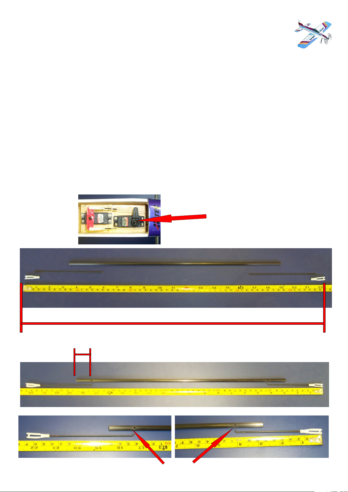
ELEVATOR SERVO AND CONTROL ROD INSTALLATION
Before you make the control rod please take into consideration that the overall length of the control rod
needs to be approximately 555mm.
Install the elevator servo in the rearmost servo tray with the output arm at the rear. To make the elevator control
push rod, take the 420mm carbon rod and 2 x 130mm metal rods which have to be fitted into the carbon rod. This is
done by putting a right angle bend on the unthreaded end of the 130mm rod. Next drill a hole in one side of the
carbon rod approximately 35mm from the end. Pass the rod through the middle of the carbon tube so the right angle
bend pokes out of the hole. You may need to file the end down so you are able to pass it through the carbon tube.
Then push the supplied balsa dowls down the centre of the carbon tube to wedge the control rod in place. When
happy glue in place with some thin cyano. Repeat procedure for both ends but ensure that with both ends fitted and
the clevises attached the complete push rod assembly is approximately 555mm long from the clevis attachment
points. It may be necessary to cut down the carbon rod before the control rods are fitted in order to achieve the
correct length. Install the elevator control horn onto the elevator using 1 x control horn, 1 x backing plate and 2 x
15mm screws ensuring that the clevis attachment point is positioned over the hinge line of the control surface and
the horn is offset to clear the carbon rod from the fin post. Once installed position the servo and the elevator in the
neutral position. Install the elevator push rod adjusting the clevises so as to achieve the neutral position of both the
servo and the elevator making sure that the control rod does not bind against the fin post.
Servo installed with servo
arm rearmost.
555mm
35mm
drill hole
Holes drilled and control rods bent ready to be inserted
Page 9
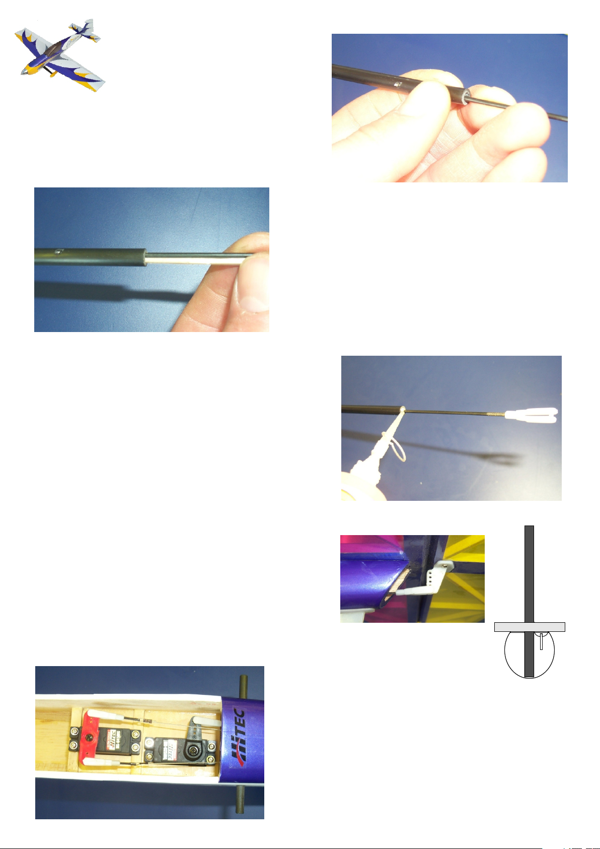
Control rod inserted into carbon
tube with the end coming out of
the drilled hole.
With the control rod inserted the
scrap balsa is pushed in to wedge
the control rod into place.
With the scrap balsa in place run thin
cyano into the balsa.
Use the control rod when connected
to the servo to align the elevator
control horn over the pivot point of
the control surface whilst ensuring
the control rod does not bind against
the fin post.
Offset horn
to clear
carbon post
Control rod connected to elevator
servo horn.
Page 10
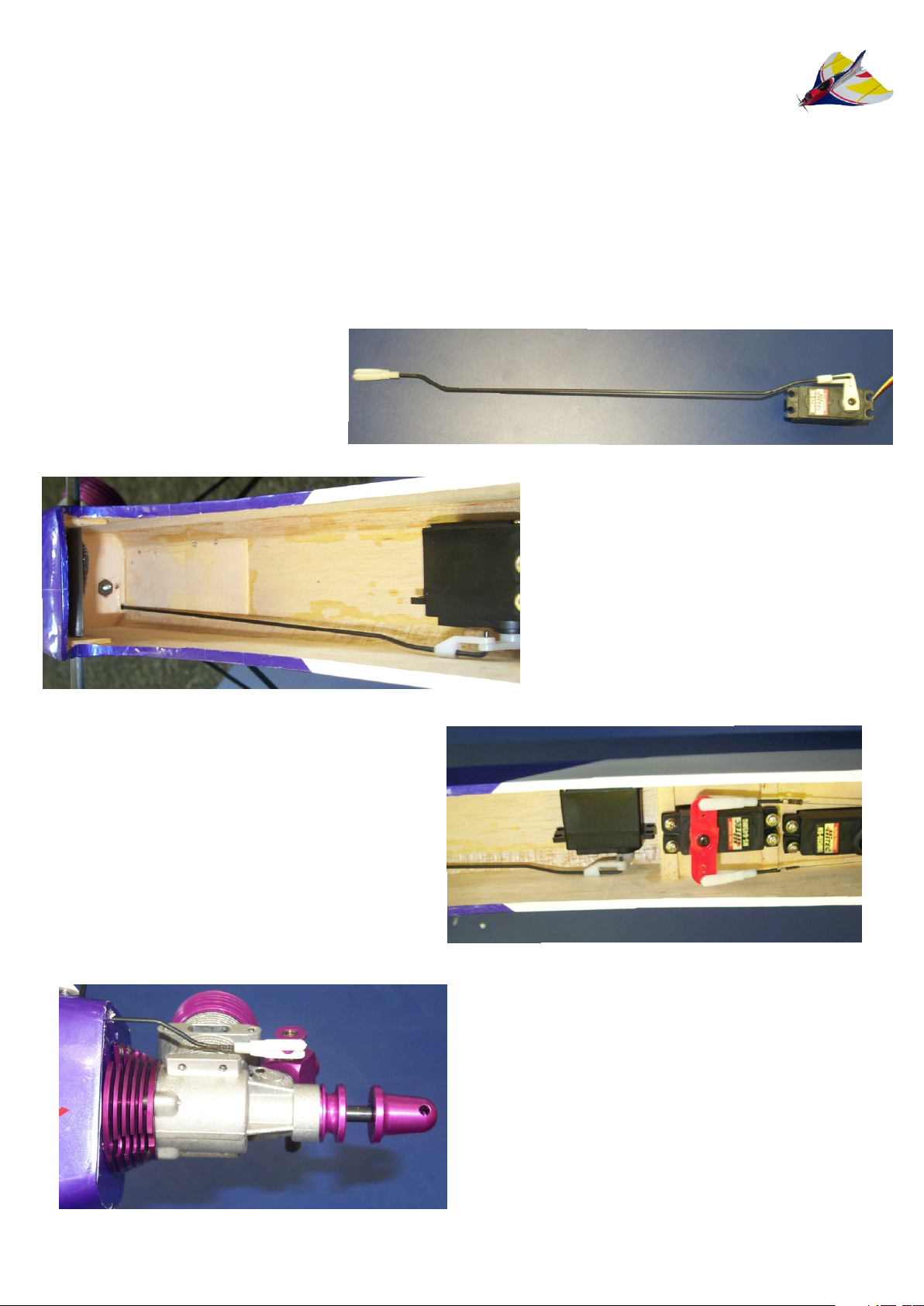
THROTTLE SERVO
To install the throttle servo it is necessary to make the control rod up as this determines
the position of the servo. Take the 290mm x 2mm rod and put the plastic clevis on the
threaded end which will be connected to the carburettor throttle lever to prevent any
metal to metal contact. A small set will be required in the rod before it goes through the
firewall to allow free and easy movement, once the rod has been passed through the
throttle servo position can be determined. The throttle servo should be mounted on its
side either by servo tape or by epoxy. Epoxy is the more secure way and a good tip is to
run some insulation tape round the servo so that if you have to remove the servo you can
just cut the tape and remove the servo. The throttle control rod is connected to the throttle
servo arm via a swing keeper and may require a set in the control rod to allow free and
easy movement. Once attached to the servo glue the servo into place.
Example of throttle
control rod.
Example of throttle
control rod running along
the bottom of the fuselage.
Example of throttle servo
position .
Example of the throttle control
rod connection to the West
36TIR
Page 11
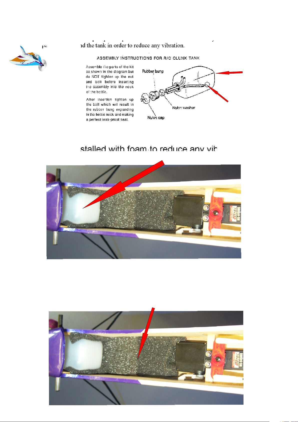
FUEL TANK
Make the fuel tank up as per the picture and install the tank. It is always good practice to
pack foam around the tank in order to reduce any vibration.
RECEIVER AND BATTERY INSTALLATION
The receiver and battery are installed behind the tank bay. You should always restrain all
plugs and the crystal to prevent any migration and pack the receiver in foam to reduce
any vibration. The battery is positioned to obtain the required C of G.
End wall of tank
The clunk should be able
to move around inside the
tank without touching the
end wall of the tank
It will be neccesary to bend two of the straight pipes to go to the top of the tank,
1 x for filling,1 x for exhaust pressure, the other straight pipe is for the clunk
which will be connected to the carb
Tank installed with foam to reduce any vibration.
Battery and receiver installation area
Page 12
C of G
For beginners:-100mm - 115mm from the leading edge of the wing
For expert :- 115mm - 135mm from the leading edge of the wing
CONTROL MOVEMENT
BEGINNERS: - Ailerons 15mm up and down ADVANCED:- Max movement
Elevators 25mm up and down Max movement
Rudder 25mm up and down Max movement
EXPO :- 15% - 35% all control surfaces
FLAPPERONS + SPOILERONS
Flapperons and spoilerons can aid the advanced flight characteristics of the Cougar
giving some incredible hover and tight-manoeuvre capabilities.
REMEMBER
Before flying check your model thoroughly and do a range check with the engine
running, check all electrical connectors are rest rained and ensure that the receiver is
padded to reduce any vibration.
We trust you will have many happy hours of flying this model and if you have any
questions do not hesitate to contact us.
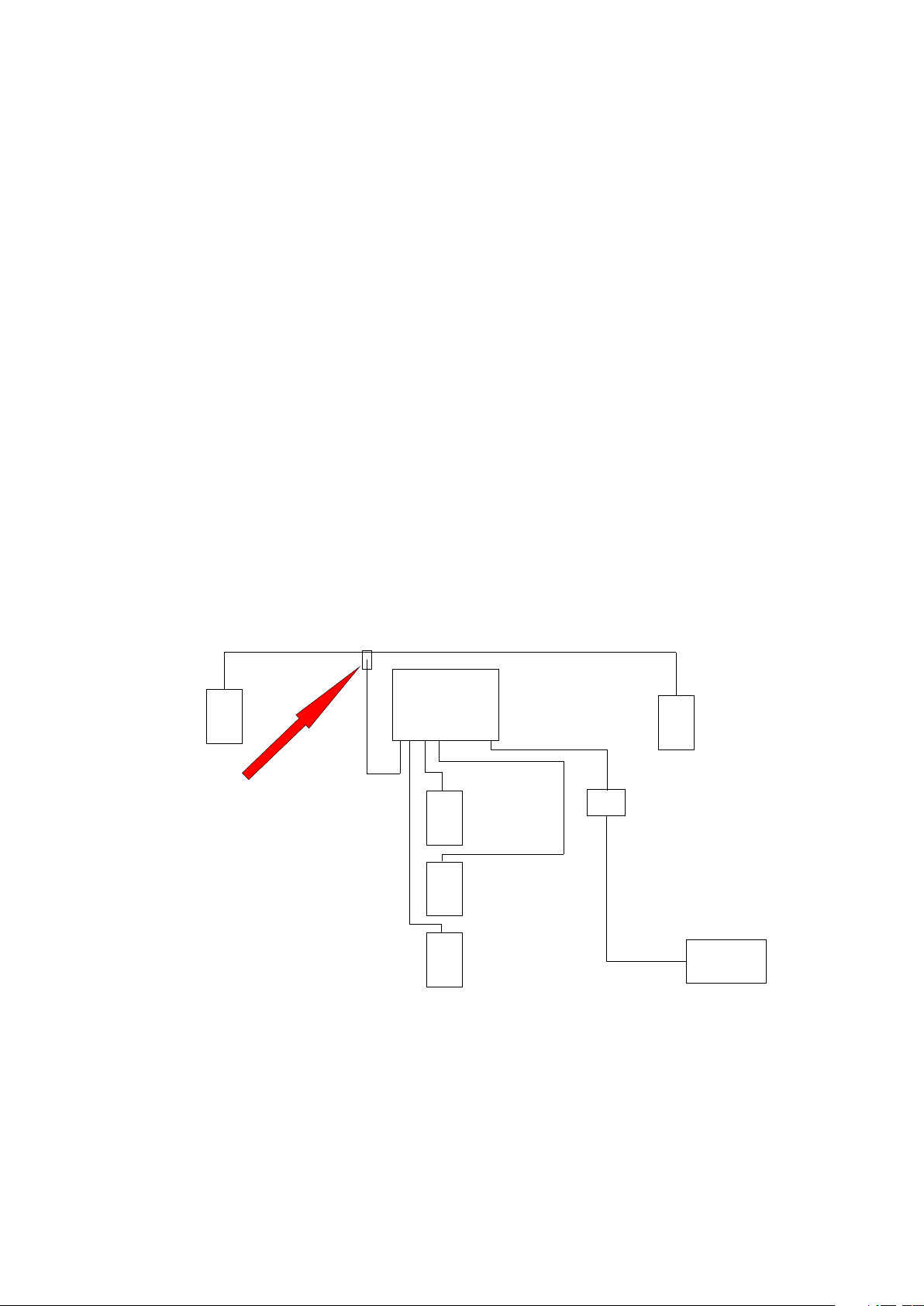
Installation wiring diagram for Futaba / Hitec (mode II)
AILERON
SERVO
RECEIVER
B
1 2 3 4 5 6 7 8
The aileron servos can be either
plugged into channel 1 via a ‘Y’ lead
or one servo can be plugged into
channel 1 and the other can be plugged
into channel 6 to utilise the facilities of
flapperons. Please see your radio
manufacturers instruction booklet
for this facility.
THROTTLE
SERVO
RUDDER
SERVO
ELEVATOR
SERVO
The switch is better mounted in the
airframe so that the On position is
S/W
to the rear. This is because when
you let go of the model your natural
tendency is to drag your hand back
and it would not be the first time
someone has switched their model
Off by doing so.
Its always good practice to lead lock all servo connections, switches and batteries to ensure they do not
become disconnected during flight. It is also good practice to run the receiver arial away from any of the
servos so no interference is picked up by the motors in the servos. Another good tip is to use clevis keepers
on all clevises
Safety
Always remember to treat your engine with respect and as soon as you connect your glow clip to your engine
to treat it as if it was running. Always keep your distance from the propeller and stand behind the engine and
propeller when you are doing high speed ground running ensuring that the plane is firmly restrained. Do not fly
if you are unsure that you are capable of doing so and make sure that you have 3rd party insurance and have
joined a club. Any needle adjustments should be done from behind the propeller ensuring you keep well clear.
. This is simply a small piece of fuel tubing slid over the clevis to keep it pinched together.
AILERON
SERVO
Battery
 Loading...