

West Marine VHF600 User Manual
VHF600_UT921ZH 5/28/04 4:24 PM Page i

This transmitter will operate on channels/frequencies that have
restricted use in the United States. The channel assignments
include frequencies assigned for exclusive use of the U.S.
Coast Guard, use in Canada, and use in international waters.
Operation in these frequencies without proper authorization is
strictly forbidden. For frequencies/channels that are currently
for use in the U.S. without an individual license, please contact
the FCC Call Center at 1-888-CALL-FCC.
Maritime Radio Services Operation
Warning!
For individuals requiring a license, such as commercial users, you should obtain
a license application from your nearest FCC field office.
West Marine works to reduce lead content in our PVC coated cords in our
products and accessories.
The cords on this product and/or accessories contain lead, a chemical
known to the State of California to cause birth defects or other
reproductive harm. Wash hands after handling.
Warning!
VHF600_UT921ZH 5/28/04 4:24 PM Page ii

About Your VHF600................................................................................2
Included With Your VHF600 ...................................................................3
Controls and Indicators...........................................................................4
Installation...............................................................................................8
Choosing a Location..........................................................................8
Engine Noise Suppression ................................................................9
Antenna Considerations ....................................................................9
Antenna Selection and Installation ....................................................9
Installing the VHF600 ......................................................................10
Operation ..............................................................................................11
Power On/Off ...................................................................................11
Last Channel Memory......................................................................11
Squelch............................................................................................12
Instant Channel 16/Channel 9 Communications.............................13
Marine Distress Procedure..............................................................13
Triple Watch.....................................................................................14
Manually Selecting a Channel.........................................................14
Weather Channels ..........................................................................15
Entering Channel Numbers into Memory Scan...............................15
Memory Channel Scan....................................................................16
Triple Watch Alert Scan...................................................................16
Alert Scan ........................................................................................16
Hail ..................................................................................................17
Adjusting the Hail Volume ..........................................................17
Weather Alert...................................................................................18
About S.A.M.E. Weather Alert ....................................................18
Setting Transmit (TX) Power ...........................................................20
Setting TX Output ............................................................................20
Sending a Distress Call ...................................................................21
Using the Menu ....................................................................................22
Menu Flow Chart .............................................................................22
Selecting Items From The Menu .....................................................22
Using Digital Selective Calling (DSC) ............................................23
Individual ....................................................................................24
Group..........................................................................................25
All Ships Call ..............................................................................26
Position Request ........................................................................27
Position Send .............................................................................28
Standby ......................................................................................30
Call Wait .....................................................................................31
Using Setup .....................................................................................33
Alarm Clock ................................................................................33
Contents
VHF600_UT921ZH 5/28/04 4:24 PM Page iii

Setting the Alarm........................................................................33
Turning the Alarm On.................................................................34
Turning the Alarm Off.................................................................35
Adjusting the Time...........................................................................36
Setting Daylight Saving Time ..........................................................37
Setting Up the Directory ..................................................................38
Entering New Information ..........................................................39
Editing Existing Information .......................................................41
Deleting Information...................................................................43
Selecting a FIPS Code ..............................................................44
Registering a New FIPS Code...................................................45
Editing a FIPS Code ..................................................................46
Deleting a FIPS Code ................................................................47
Auto Channel Switch .......................................................................49
Position Reply..................................................................................50
Channel Name (CH Tag).................................................................52
Editing a Channel Name............................................................52
Defaulting a Channel Name.......................................................54
Setting Up a U.I.C. ..........................................................................55
Setting Up a WHAM (Wireless Handheld Access Microphone)......56
Setting a Base ID.......................................................................57
Changing the Link Channel .......................................................58
Setting Up a Group MMSI (Marine Mobile Service Identity) ...........59
Setting Up a User MMSI .................................................................60
Setting Up The System ...................................................................62
Setting the Contrast ...................................................................62
Setting the Backlight ..................................................................63
Setting the Key Beep .................................................................64
Reviewing Channel Memory ...........................................................65
NMEA Technical Setup .........................................................................66
Connecting a GPS Receiver to the Radio.......................................66
Optional Accessories ............................................................................66
VHF FM Marine Radio Telephone Channel and Functions..................67
USA Channels .................................................................................67
International Channels.....................................................................68
Canadian Channels .........................................................................69
NWR-SAME Event Codes ....................................................................70
Specifications........................................................................................71
Troubleshooting ....................................................................................72
Care and Maintenance .........................................................................74
Three Year Limited Warranty................................................................76
VHF600_UT921ZH 5/28/04 4:24 PM Page iv

2
Your West Marine VHF600 marine radio is a potent combination of high
technology fused with rugged durability. The radio's all solid-state design
and conservatively-rated components and materials make it an ideal
choice for harsh marine environments.
The radio is constructed to be well-protected from the elements and
meets the stringent JIS7 waterproof specification. You can use an optional
flush mount (600 FMB) to mount the radio for maximum convenience
aboard your vessel.
The radio's built-in DSC (Digital Selective Calling) options let you send a
distress message in an emergency situation, and send and receive
position data to and from other vessels. The radio's built-in weather alert
function helps you stay abreast of the latest weather conditions. You can
even connect an optional GPS receiver to the radio to help keep track of
your current location with space-age precision.
You should read the rest of this Operating Guide throughly to acquaint
yourself with all of your radio's features and functions.
Save your receipt as proof-of-purchase in case you ever need to have
warranty service on the radio.
Features, specifications, and availability of optional accessories are all
subject to change without notice.
Note: Your radio meets JIS7 requirements. This means that the radio and
microphone can be submerged to a depth of 1 meter for up to 30 minutes
without incurring damage.
About Your VHF600
VHF600_UT921ZH 5/28/04 4:24 PM Page 2

3
Included With Your VHF600
VHF600 Owner’s Manual VHF600 Radio Microphone Hanger
and Screws
Mounting Bracket
and Knobs
DC Cord
Spare Fuse
250V 6A
Accessory CableMounting Hardware
VHF600_UT921ZH 5/28/04 4:24 PM Page 3
4
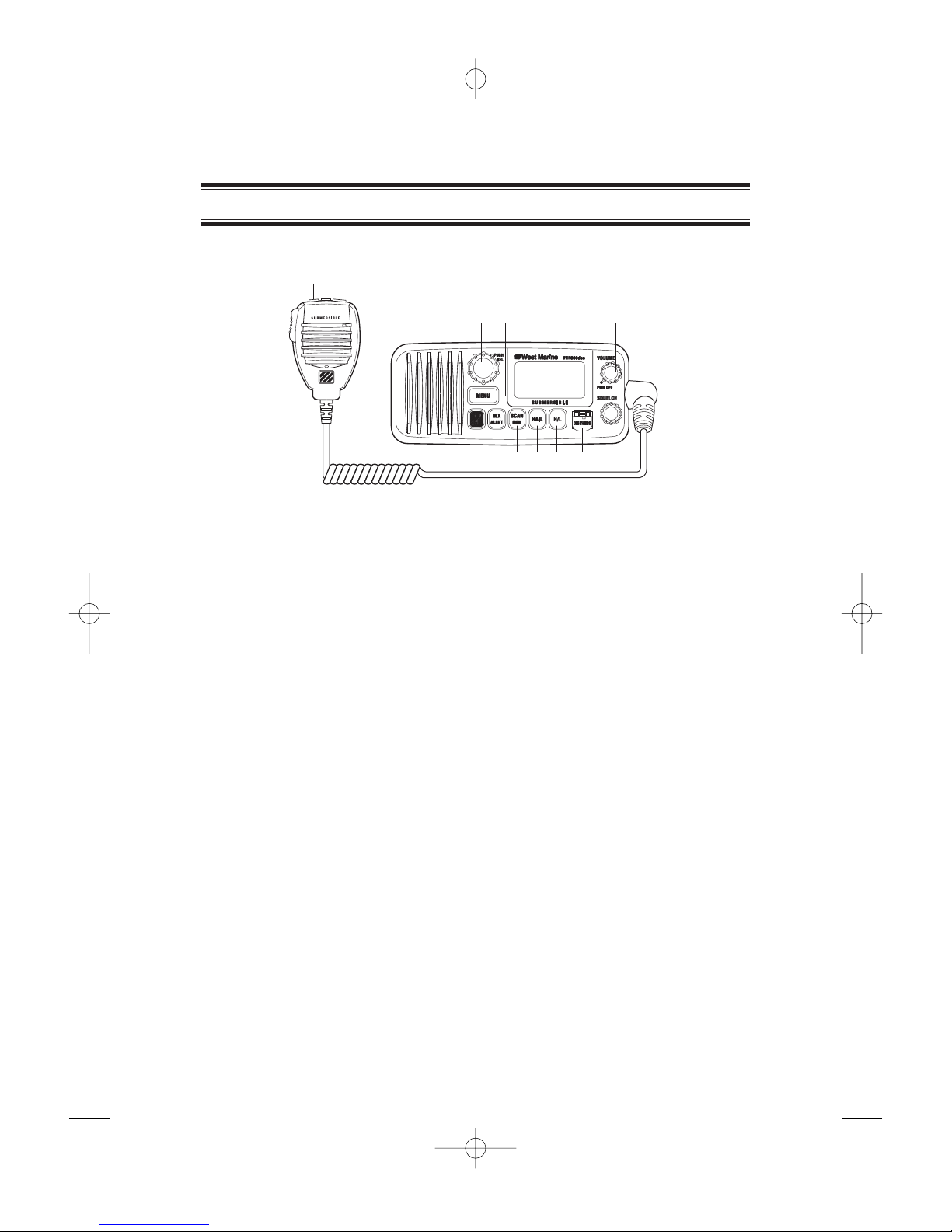
Front Panel/Microphone
1. PTT Switch - Press to transmit and release to receive.
2,7.
16/9/TRI - Press briefly to instantly change to Channel 16, Channel 9 or the
current channel. Press for more than two seconds to activate the Triple
Watch Feature.
3.
+/-- These keys are used to change the channel number up or down. They
are also used to adjust the outgoing volume for Hail mode and to move the
cursor in Menu mode.
4.
PUSH/SEL - This is used to manually select the desired Communication
Channel (01-28 and 60-88), or Weather Channel (0-9).
In the Menu mode this is used to select the menu options. It is also used to
display the GPS mode and to adjust the outgoing volume for the HAIL
mode.
5.
MENU - Press briefly to enter the Menu mode.
6.
PWR(Power)/VOLUME (On/Off/Volume) - Turns the unit on or off and
adjusts the speaker volume.
8. WX/ALERT - Selects Weather channel and Weather Alert mode. Press
briefly to listen to active NOAA Weather channels. Press and hold for 2
seconds to set the radio to its Weather Alert mode.
9.
SCAN/MEM - Press briefly to activate the memory channel scan feature.
Press for more than two seconds to place the currently selected channel into
memory. Press for more than two seconds again to delete a channel from
scanning memory.
10.
HAIL - Use as a public address system and for two-way voice
communication.
11. H/L - Press briefly to change the transmit power to either High (25 watts) or
Low (1 watt).
12. DISTRESS - Lift the flap and press this key for 5 seconds to send a
distress signal in case of emergency.
13.
SQUELCH - Rotate clockwise to eliminate background noise when a signal
is not being received.
Controls and Indicators
1
2
3
4
5
6
7 8 9 10 11 12 13
VHF600_UT921ZH 5/28/04 4:24 PM Page 4
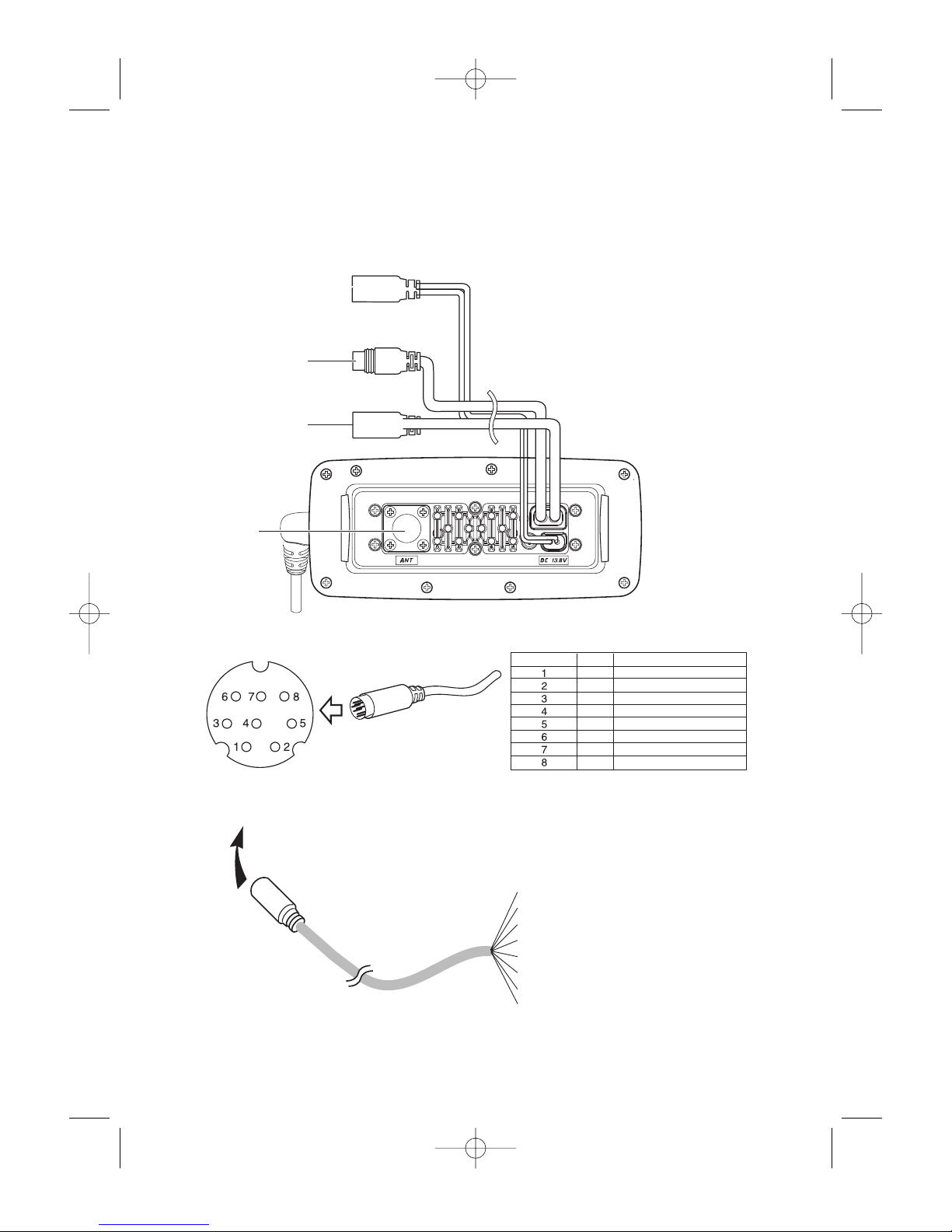
5
Rear Panel Connectors
2
1
3
4
1. DC Jack
2. ACC Connector
3. Remote Connector
4. Antenna Connector
To VHF600
Orange : NMEA OUT (-)
Black : External Speaker (
-
)
Green : GPS DATA IN (+)
Red : External Speaker (+)
Bare Wire : GPS DATA IN (
-
)
Brown : Hailer (+) Horn Speaker
Blue : Hailer (—) Horn Speaker
Yellow : NMEA OUT(+)
Color
ORG
RED
BRN
GRN
YEL
BAR
BLK
BLU
Signal
NMEA OUT (
-
)
External Speaker (+)
Hailer (+) Horn Speaker
GPS DATA IN (+)
NMEA OUT (+)
GPS DATA IN (
-
)
External Speaker (
-
)
Hailer (
-
) Horn Speaker
Pin number
ACC Connector
VHF600_UT921ZH 5/28/04 4:24 PM Page 5
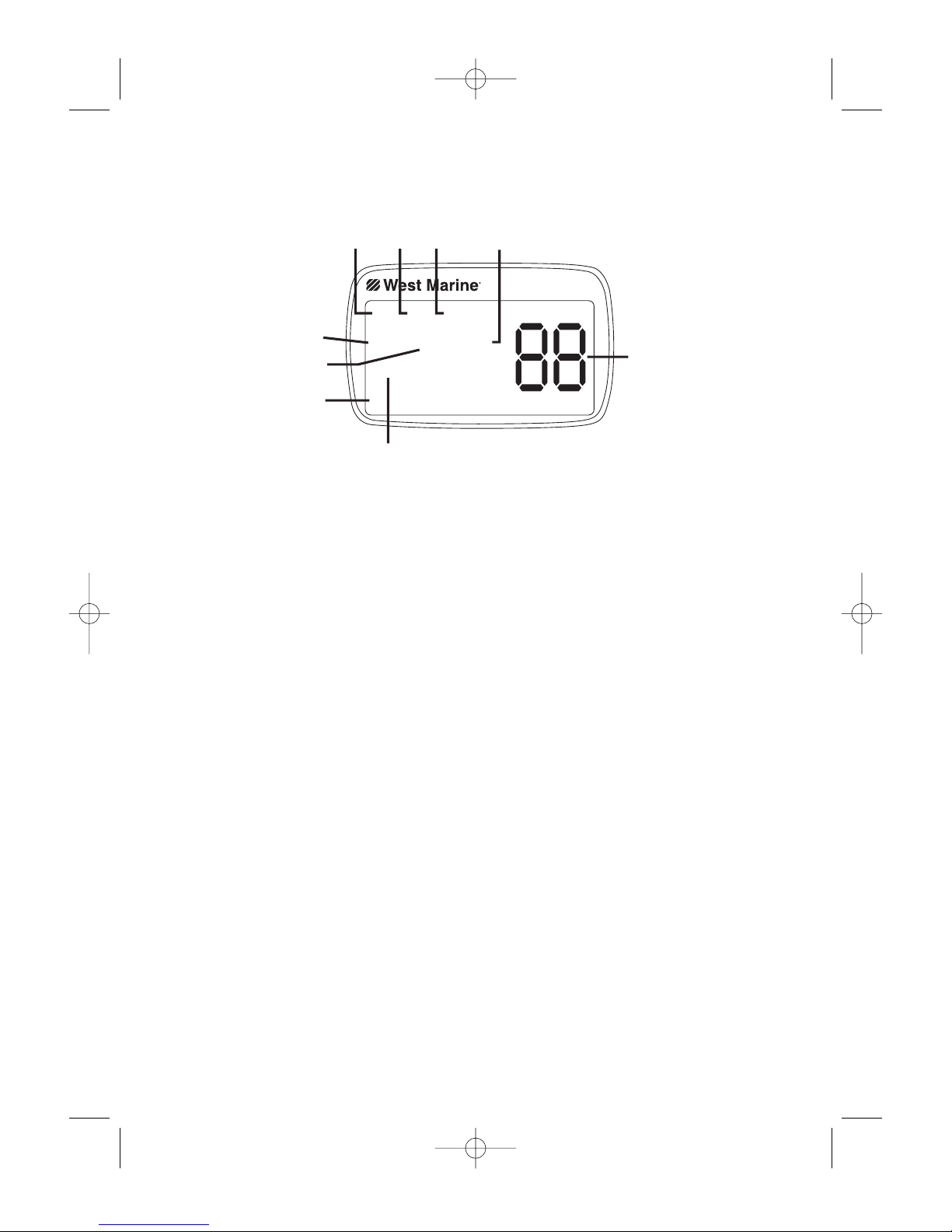
6
1. TX (Transmit) - Indicates the radio is transmitting.
TRI (Triple Watch) - Indicates Triple Watch Mode is in effect.
2.
HI (High) - Indicates transmit output is 25 watts.
LO (Low) - Indicates transmit output is 1 watt.
3.
USA - Indicates US Channel Mode.
CAN - Indicates Canadian Channel Mode.
INT - Indicates International Channel Mode.
4.
ALT - Indicates Weather Alert Mode has been activated.
5.
MEM (Memory) - Indicates Memory Scan Mode status for each
selected channel.
6.
WX - Indicates Weather Channel Mode has been activated.
7.
CHANNEL NAME - Shows the currently-tuned channel’s name.
8.
Channel Display - Indicates the current Channel Number.
9.
ALARM SET - Appears when the alarm is set.
9.
ALARM ACTIVE - Blinks when the alarm clock is sounding.
9.
GPS OK- Appears while the VHF600 is receiving valid GPS data
from an external GPS receiver (GPS receiver is optional).
9.
CHECK GPS - Appears when the GPS data is invalid.
9.
WHAM (Wireless Handheld Access Microphone) OK - Appears
when the VHF600 is connected to the WHAM’s control unit.
9.
BATTERY HIGH - Appears when the battery voltage is too high.
(The Battery High icon appears in this illustration).
9. BATTERY LOW - Appears when the battery voltage is too low.
TX HI USA
MEM WX ALT
GPS OK
DISTRESS,SAF
VHF600
1
23 4
8
5
6
7
9
VHF600_UT921ZH 5/28/04 4:24 PM Page 6

7
1. Date - Shows current date.
2.
Time - Shows current time.
3.
Speed Data - Shows current speed.
4.
Angle Data - Shows current compass direction.
5.
Latitude - Shows current position information.
6.
Longitude - Shows current position information.
7.
Channel Display - Shows the currently-tuned channel.
06/20 11:00P
208± 30.OKT
35± 40.610 N
139± 46.564 E
VHF600
1
23
7
4
5
6
GPS Indicator (External GPS Source Required)
The GPS Indicator screen appears if you connected an optional GPS
receiver to the radio and press the PUSH – SEL knob.
Notes: ● "POS SEND", "TIME ADJUST", "DAYLITE SAVINGS", and "ALARM
CLOCK" do not appear on the display if an external GPS receiver is
not connected to the radio.
● When the radio is in one of the following modes: WX Alert mode,
Channel 16/9 mode, Scan Mode, or Triple Watch mode and the
user presses
MENU, all of these modes are cancelled.
● The Menu mode is cancelled if the radio receives a DSC call or any
key except
+ / -or the PUSH – SEL knob is pressed.
VHF600_UT921ZH 5/28/04 4:24 PM Page 7

8
Installation
Caution: The VHF600 will only operate with a nominal 13.8 volt
negative ground battery system.
Keep in mind the flexibility designed into the VHF600 so that you can
most conveniently use it. Features which should be considered are:
1. The universal mounting bracket may be installed on either the top
or bottom of a shelf, on a bulkhead, or for overhead mounting.
2. The REMOTE speaker wires can be used with an auxiliary speaker.
3. All connections are "plug-in" type for easy removal of the radio.
4. By using an optional WHAM (Wireless Handheld Access
Microphone), the
VHF 600 can be mounted completely out of the
way.
5. Also optionally available is a flush mount bracket (White FMB600).
Choosing a Location
Some important factors to consider in selecting the location for your
VHF600.
1. The
VHF600 is completely waterproof, but will last longer if
protected from spray and splash.
2. Keep the battery leads as short as possible. Direct connection to
the battery is most desirable. If direct connection can not be made
with the supplied power lead, any extension should be made with
#12-14 AWG wire. Long extensions should use larger gauge wire.
3. Keep the antenna lead-in wire as short as possible. If you must
use a long lead-in wire as in the case of a sailboat masthead
antenna installation, we recommend you upgrade your lead-in
wire according to the following table:
RG-58 <20'
RG-8X <35'
RG-8U <60'
4. Locate your antenna as high as possible and clear from metal
objects. The reliable range of coverage is a direct function of the
antenna height.
5. Select a location that allows free air flow around the heat sink on
the rear of the radio.
6. Select a location well away from the ship’s compass. Auxiliary
speakers also should be located away from the compass.
VHF600_UT921ZH 5/28/04 4:24 PM Page 8

9
Engine Noise Suppression
Interference from the noise generated by the electrical systems of
engines is sometimes a problem with radios. The VHF600 has been
designed to be essentially impervious to ignition noise and alternator
noise. However, in some installations it may be necessary to take
measures to further reduce the effect of noise interference. The
VHF600 radio DC battery wires, antenna lead, and accessory cables
should be routed away from the engine and engine compartment, and
from power cabling carrying high currents.
In severe cases of noise interference, it may be necessary to install a
noise suppression kit. Contact your West Marine store or dealer where
you purchased the radio for more information.
Antenna Considerations
A variety of antennas are available from a number of quality suppliers.
In general, we recommend 8’ 6dB rated antennas for powerboats, and 4’
3dB antennas for sailboats.
In general, communication range is increased by using a high-gain
antenna placed as high as possible above the water line. Antennas
should be located away from metal objects. Keep coax feed cables as
short as practical.
Antenna Selection and Installation
Your VHF600 has been designed to accommodate all of the popular
marine VHF antennas. However, the selection and the installation of the
antenna is the responsibility of the user or installer.
The FCC has determined that excessive radiation poses a health risk to
people near radio transmitting antennas. Therefore, the antenna used
with this radio should be installed using the following guidelines to
ensure a suitable distance between the antenna and persons close by.
● Small whip antennas (3 dB) or smaller should be installed keeping at
least 3 feet separation distance between the radiating element and
people.
● Larger antennas (6 dB or 9 dB) should be installed keeping at least
a 6 feet separation distance.
● No person should touch the antenna or come closer than the
separation distance when the radio is transmitting.
VHF600_UT921ZH 5/28/04 4:24 PM Page 9
10
Installing the VHF600
After you have carefully considered the various factors affecting your
choice of location, position the radio (with the bracket, microphone,
power cord, antenna and any auxiliary cables installed) into the selected
location to assure there is no interference with the surrounding items.
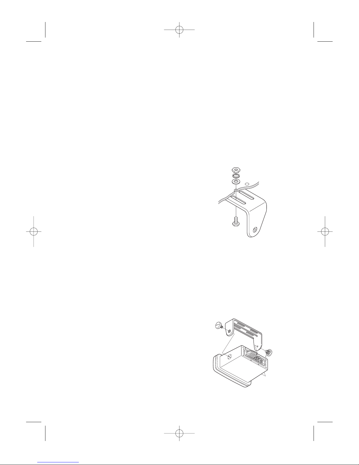
Mark the location of the mounting bracket. Remove the bracket from the
radio and use it as a template to mark the holes to be drilled for the
mounting hardware. Drill the holes and mount the bracket with
hardware compatible with the material of the mounting surface.
Note: This HEXAGON HEAD BOLT is
only for mounting the bracket
with hardware. Do not use it for
installing the radio in the
mounting bracket.
Connect the red wire of the supplied power cord to the positive (+) side
of your distribution circuit or battery. Connect the black wire of the
supplied power cord to the negative (–) side of your distribution circuit or
battery. The power cord is equipped with a fuse to protect the radio.
Use only a six (6) amp fast blow fuse for replacement. Connect the
power cord to the keyed connector on the power "pigtail".
Connect the antenna and all other auxiliary cables and accessories.
Install the radio in the mounting bracket and connect all cables and
accessories to the appropriate jacks and connectors.
Note: Do not use mounting knobs other
than the ones supplied. Do not
insert the knobs without attaching
the bracket.
VHF600_UT921ZH 5/28/04 4:24 PM Page 10
11
Power On/Off
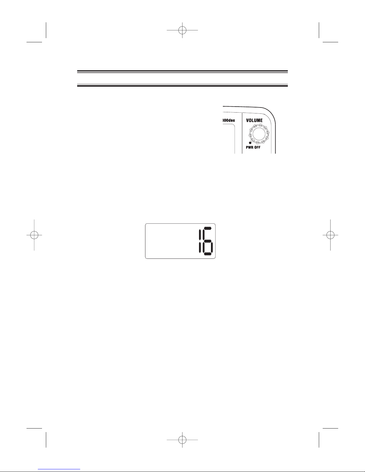
Turn on the radio by rotating the
PWR/VOLUME control clockwise.
Then adjust the volume to a comfortable
level.
When you turn on the radio, you hear a
beep and the greeting message below
appears on the display for 2 seconds. Then the main display shown on
page 6 appears on the display.
To toggle between the main display and the GPS Indicator screen (if you
install an optional GPS receiver), repeatedly press the
PUSH – SEL
knob.
Operation
WEST MARINE
VHF600 DSC
MARINE
RADIO
Last Channel Memory
The VHF600 memorizes the last channel selected before you turn it off.
For example, if the VHF600 is tuned to Channel 16 when you turn it off,
it tunes that channel when you turn it back on.
Note: You must tune a channel for at least 3 seconds before the
radio will memorize that channel.
VHF600_UT921ZH 5/28/04 4:24 PM Page 11
12
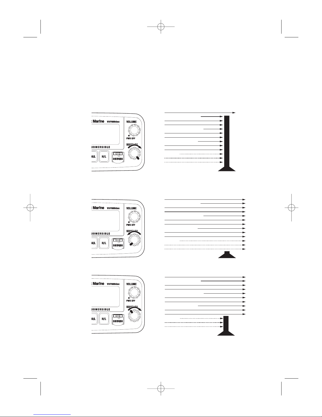
Turn SQUELCH fully clockwise. This raises the “Squelch Gate” so high
that only very strong signals can get through.
Turn
SQUELCH fully counterclockwise until you hear a hiss. This lowers
the “Squelch Gate” so that everything gets through - noise, weak
signals, and strong signals.
Turn
SQUELCH back clockwise until the hiss stops. Now the “Squelch
Gate” allows only strong signals to get through.
Strong Signals
Medium Signals
Weak Signals
Noise
Strong Signals
Medium Signals
Weak Signals
Noise
Strong Signals
Medium Signals
Weak Signals
Noise
Squelch
VHF600_UT921ZH 5/28/04 4:24 PM Page 12
13
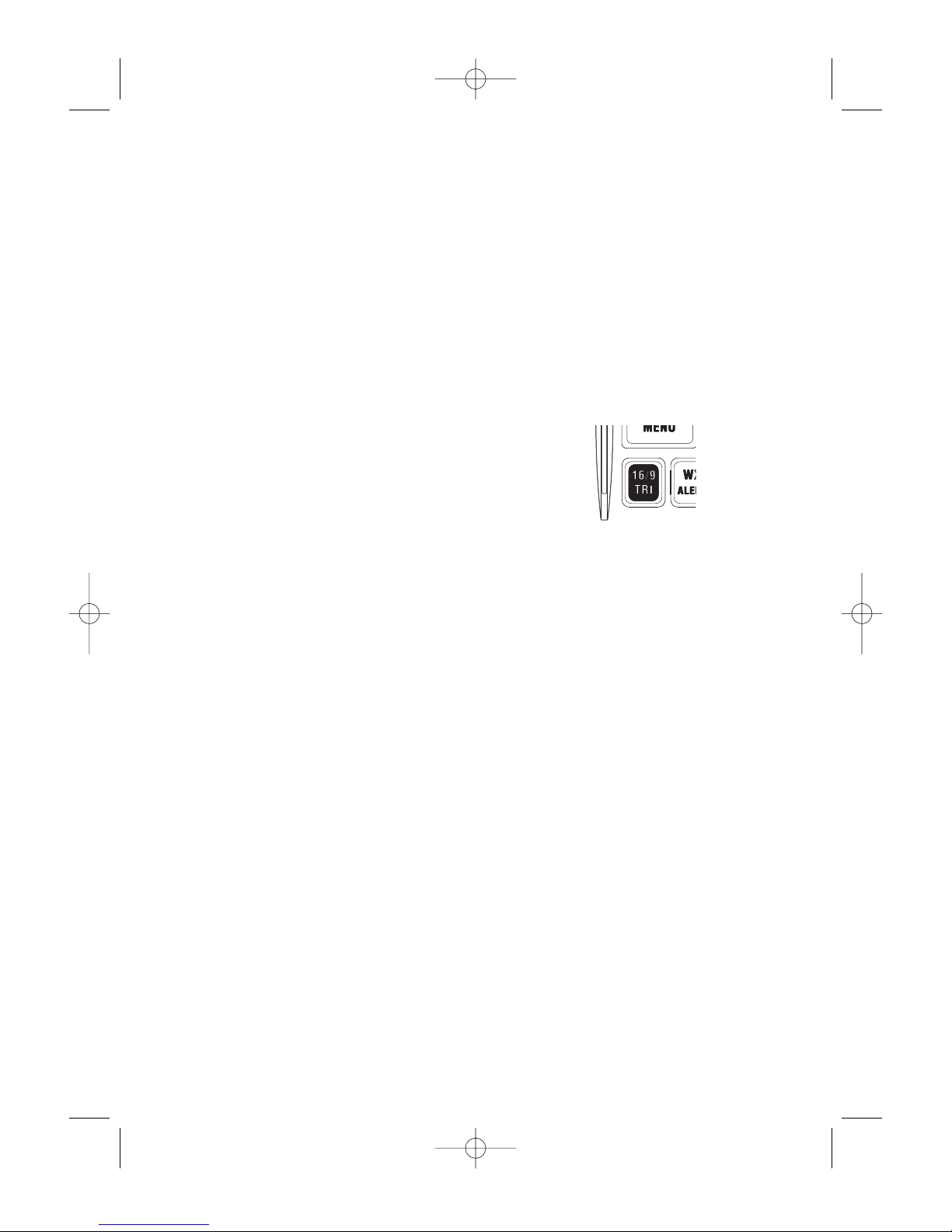
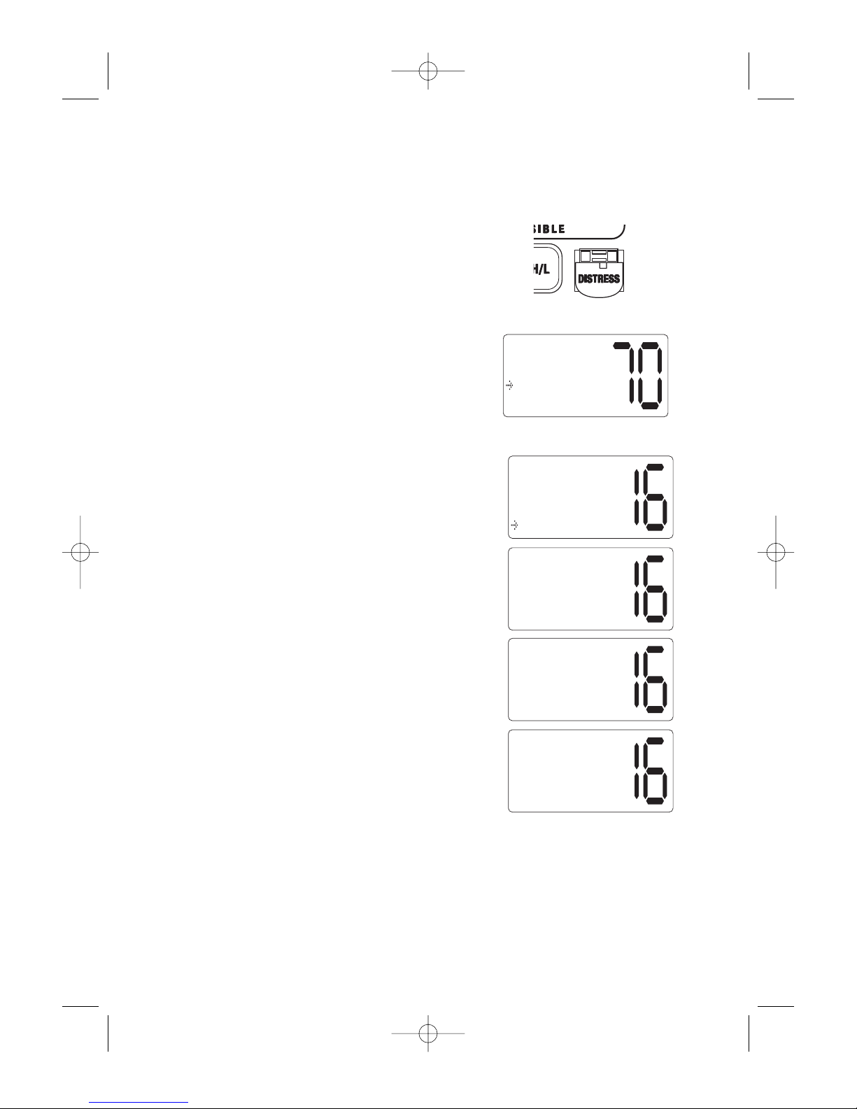
Instant Channel 16/Channel 9 Communications
The radio tunes to Channel 16 (Hailing and Distress) the first time you
press the 16/9/TRI key, even if it is tuned to another channel. The radio
tunes to Channel 9 (Hailing and Distress) the second time you press the
16/9/TRI key. Press 16/9/TRI a third time to return to the original
channel you tuned before you pressed 16/9/TRI. The selected channel
appears on the display.
To cancel Hailing and Distress Channel 16/Channel 9 communications:
● Repeatedly press 16/9/TRI until the
previous channel setting appears.
--or--
● Briefly press WX/ALERT, + / - on
the microphone, or SCAN/MEM.
MARINE DISTRESS PROCEDURE
Speak slowly – clearly – calmly.
1. Make sure the radio is on.
2. Tune to Channel 16.
3. Press the PTT button on the microphone then say: "MAYDAY –
MAYDAY – MAYDAY."
4. Give your vessel’s ID.
5. Say "MAYDAY [your vessel’s name]."
6. Give your location (including any nearby navigational aids or
landmarks).
7. State the nature of your distress.
8. Give the number of persons aboard and the conditions of any
injured.
9. Estimate present seaworthiness of your vessel.
10. Give a brief description of your vessel (meters, type, color, hull).
11. Say: "I will be listening on Channel 16".
12. End message by saying "THIS IS [your vessel’s name or call sign]
OVER."
13. Release the PTT button and listen. Someone should answer.
If not, repeat the call, starting at Item 3 above.
VHF600_UT921ZH 5/28/04 4:24 PM Page 13

Manually Selecting a Channel
To manually select a channel, rotate the PUSH – SEL knob clockwise to
increase the number or counterclockwise to decrease it. You can also
repeatedly press + or -on the microphone to change it.
Communication channels are located on channel 01-28 and 60-88.
Weather channels are located on channels 0-9.
Note: In the US, the Coast Guard may refer to Channels 21, 22, 23
etc. as 21 alpha, 22 alpha, etc. The VHF600 shows these
channels in the USA mode as channel 21, 22, 23, etc.
14
Triple Watch
Triple Watch lets you monitor Channel 16, Channel 9, and the current
Marine Channel (home or normal channel) or Weather Channel.
To activate Triple Watch, press and hold
16/9/TRI for 2 seconds. TRI
appears on the LCD, indicating Triple Watch mode is in effect. If a signal
is received on Channel 9 the radio keeps watching channel 16.
Press and hold 16/9/TRI for 2 seconds to cancel the Triple Watch mode.
Note: While in Triple Watch mode, you can change the currently
selected channel using the PUSH – SEL knob.
A momentary press of the 16/9/TRI button interrupts Triple
Watch mode and remains on channel 16, or on channel 9 if
you press 16/9/TRI once more. To return to the Triple Watch
mode, simply press the button briefly again.
88
TRI HI CAN
MEM
TRIPLE
WATCHING
VHF600_UT921ZH 5/28/04 4:24 PM Page 14
15
Weather Channels
To select Weather Channels 0-9, press
WX/ALERT briefly. The radio will tune to
the last selected Weather Channel. Press +
or -on the microphone to select a
different Weather Channel. It also can be
changed by the PUSH – SEL knob on the
base.
To exit the Weather Channel, press
WX/ALERT briefly The radio returns to the
previous Marine channel.
Entering Channel Numbers into Memory Scan
You can enter channels into the radio’s memory so they can be rapidly
scanned. This means that you can have the radio move from one
memorized channel to the next, and have it stop to monitor the channel
only if there is traffic or conversations on that channel.
To enter a channel into Memory Scan,
select the channel you want to store by
rotating the PUSH – SEL knob, then press
and hold SCAN/MEM for 2 seconds. The
channel is stored in Memory Scan and MEM
appears on the LCD display.
WX
WEATHER 1
88
HI CAN
MEM
MAR OPERATOR
VHF600_UT921ZH 5/28/04 4:24 PM Page 15

16
To cancel the channel in memory, press and hold SCAN/MEM for 2
seconds. The MEM icon disappears.
Note: The Memory channel can be set independently in 3 regional
modes (USA, INT, and CAN). You cannot use this feature in
WX mode or for channel 70.
Memory Channel Scan
This feature will allow you to scan only the channels of your choice.
Memory Channel Scan can only be activated if channels have previously
been placed into memory.
To turn on Memory Channel Scan, press
SCAN/MEM. The VHF600
scans the channels that were previously placed into memory, from the
lowest channel number to the highest channel number.
Triple Watch Alert Scan
This feature will allow you to listen to the channel of your choice. scan
channels 16 and 9 every 2 seconds, and scan for Emergency or
Weather Alerts every 7 seconds to be sure that you will not miss any
important broadcasts.
To turn Triple Watch Alert Scan on, press and hold
WX/ALERT for
2 seconds while in Memory Channel Scan mode. While the Memory
Channels are scanned, Channel 16 and Channel 9 are scanned every 2
seconds, and the Weather Channel is scanned every 7 seconds. "TRI"
and "ALT" appear on the display.
Alert Scan
This feature will allow you to scan the channels of your choice and also
scan the Weather channels for Emergency or Weather alerts.
To turn Alert Scan On, press and hold WX/ALERT for 2 seconds. While
the memory channels are scanned, the Weather Channel is scanned
every 7 seconds. The icon appears on the display.
VHF600_UT921ZH 5/28/04 4:24 PM Page 16
17
HA
HAIL VOLUME
¡¡¡¡¡¡¡¡¡
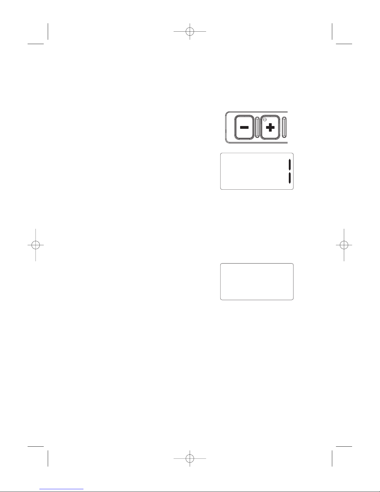
Adjusting the Hail Volume
While you are in Hail mode, you can adjust the outgoing volume by
pressing +/-on the microphone, or by rotating the PUSH – SEL knob
on the VHF600. The incoming volume is adjusted by using the
PWR/VOLUME knob.
Hail
To access the Hail mode, press HAIL on the base. HA appears on the
display. Press and hold the PTT switch on the microphone, hold the
microphone approximately two inches away from your mouth, and speak
clearly in a normal voice. To cancel Hail mode, press HAIL on the base
again.
Note: If you purchase an optional hailer horn for the radio, make sure
it meets these specifications.
• 17 Watts (nominal)
• 10 Watts (minimum)
• 4 Ω load (impedance)
* RE-ENTRANT feature might not work on all models.
VHF600_UT921ZH 5/28/04 4:24 PM Page 17

18
Weather Alert
Traditional weather radios receive weather broadcasts (usually within a
50-mile radius) then sound an alarm when any emergency code is
transmitted along with the broadcast. This means that people who live
outside an affected area are often alerted even when their area is not
affected, causing many of them to ignore potentially real
emergency/weather warnings that can save lives.
Your radio’s Weather Alert feature lets it monitor the local weather
channel for NOAA weather alert broadcasts, while allowing you to listen
to other channels.
About S.A.M.E. Weather Alert
In 1994, the National Oceanic and Atmospheric Administration (NOAA)
began broadcasting coded signals called FIPS (Federal Information
Processing System) codes along with their standard weather broadcasts
from stations in your area. These codes identify an emergency and the
specific geographic area (such as a county) affected by the emergency.
Your radio’s SAME (Specific Area Message Encoding) technology lets it
receive, interpret, and display information about the codes it receives so
you can determine if an emergency might affect your area.
Each FIPS code identifies a specific geographic area (defined by the
National Weather Service), so your radio sounds an alert only when an
emergency/weather emergency is declared in those locations. This
helps you more efficiently track the emergency/weather conditions in
and around your area.
When the
VHF600 receives a weather alert:
• It sounds an alert siren.
• A description of the alert appears.
The alert descriptions your radio can display are based on a list of
specific weather alert types published by the NWS (National Weather
Service). For a list of all the alert descriptions that your radio can
display, see “NWR-SAME Event Codes” on page 70.
Caution: The NWS uses sophisticated weather models to determine an
alert’s effective time. However, the end of an alert does not
necessarily mean that the related weather emergency is over.
VHF600_UT921ZH 5/28/04 4:24 PM Page 18
19
The radio’s Weather Alert mode can alert you when dangerous weather
is in your area. When Weather Alert is turned on and a warning signal is
received, an emergency siren sounds at full volume, regardless of the
volume setting. When the signal stops, you hear the active weather
channel broadcast at its normal volume.
Note: See “Selecting a FIPS Code” on page 44 for more information
about working with FIPS codes.
1. Press WX/ALERT for more than
2 seconds when WX/ALERT is off.
The radio turns WX/ALERT on and
the ALT icon appears.
2. If the radio receives a 1050Hz tone,
the ALT icon blinks every other
second.
3. When a WX/ALERT signal is
received, all other functions are
canceled and the radio remains on
the selected weather channel.
Important: The radio does not decode a SAME signal when it is in Scan
mode. To decode the SAME signal, set the radio to an active
weather channel.
To stop the alert, briefly press any key. If you press any key
again, the alert icon disappears.
Note: The radio must be tuned to an active weather channel to
decode the SAME signal. This is because the SAME signal is
only broadcast at the beginning of the 10 second weather alert
tone broadcast by the National Weather Service.
WX ALT
WEATHER 1
WX ALT
ALERT DETECT
WX ALT
WARNING
TSUNAMI
The ALT icon indicates the Weather Alert mode is active. To activate the
Weather Alert mode:
VHF600_UT921ZH 5/28/04 4:24 PM Page 19
20
Setting Transmit (TX) Power
The VHF600 transmits on 55 marine frequencies and receives on 80
marine frequencies. Channel 70 of the USA, International, and Canadian
frequencies, and channel 15, of the USA frequencies, and WX CH – are
for receiving only. The VHF600 transmits on channel 70 when sending
DSC information. Your radio will not transmit on these channels. For
your reference, a listing of all the available marine channels is located
on pages 67 - 69.
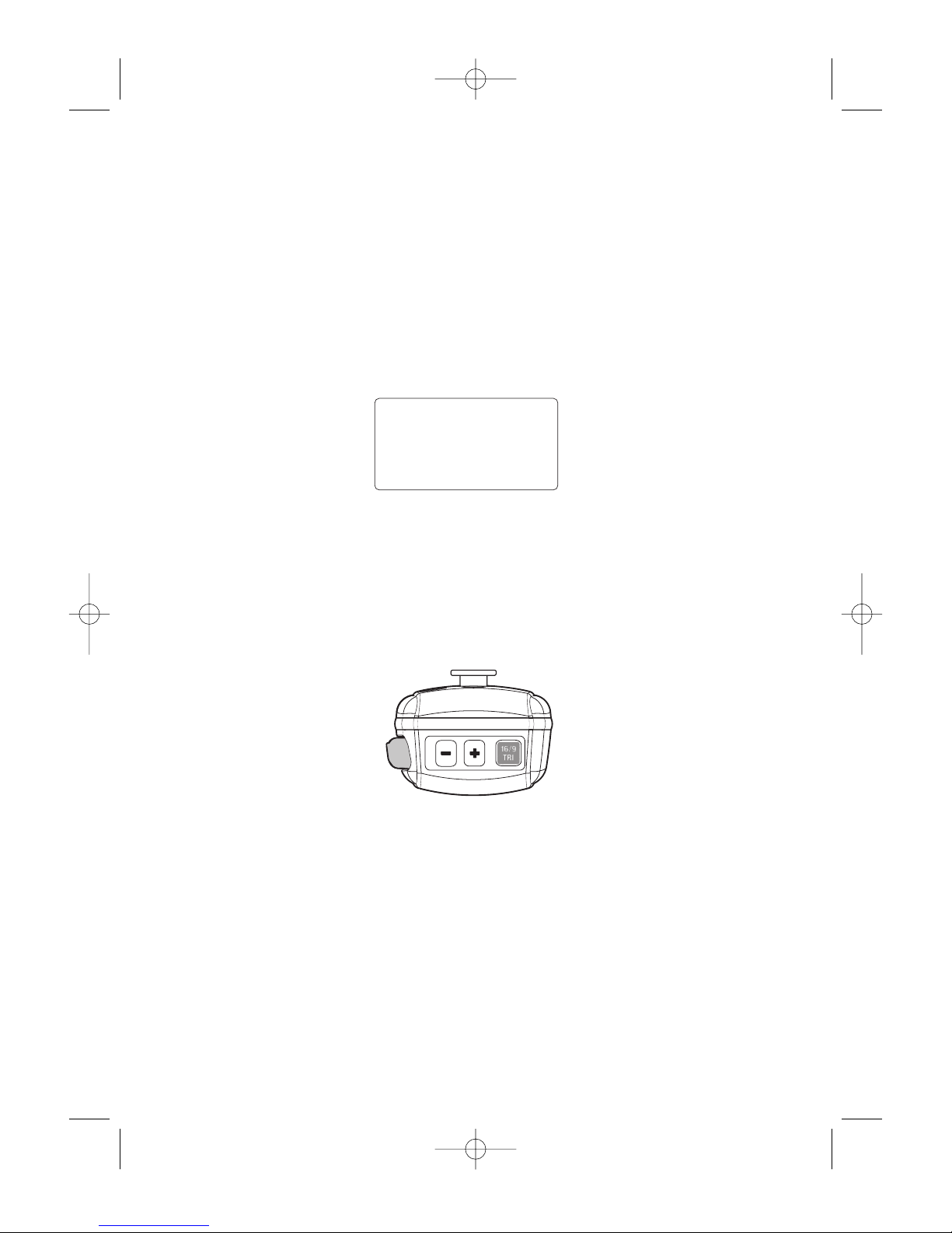
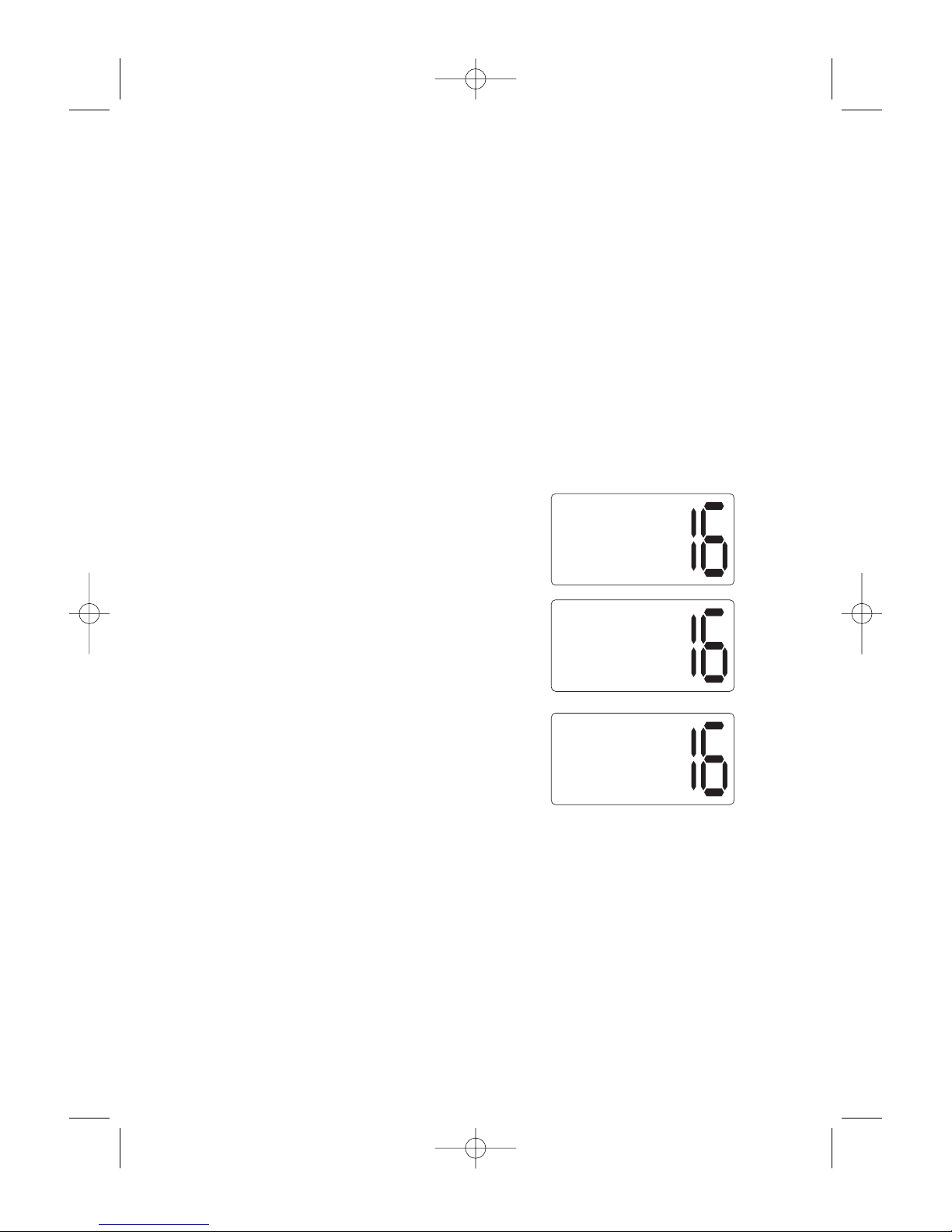
Setting TX Output
Caution: Be sure to set the TX output to LO while in port or for short
range communications.
1. When you turn the VHF600 on for
the first time, it is automatically set to
transmit at 25 watts (HI).
2. Press H/L briefly to change the
transmitter output to 1 watt (LO).
3. Press
H/L again to change back to
25 watts (HI).
Note: A short tone sounds every time you press H/L.
CH13 is a 1 watt (LO) channel. When the channel is a LO
power channel, you can transmit at 25 watts (HI) by pressing
H/L during the call. LO power channels are USA Channels 13,
17, 67, 77; Canadian Channels 13,15,17,20,66,77, and INT
Channels 15,17. Use low transmit power in harbors or when
close to the receiving station. You cannot change the transmit
power setting on channels which are receive-only channels,
including all weather channels, USA Channels 15, 70,
Canadian Channel 70, and International Channel 70.
HI USA
DISTRESS
LO USA
DISTRESS
HI USA
DISTRESS
VHF600_UT921ZH 5/28/04 4:24 PM Page 20
21
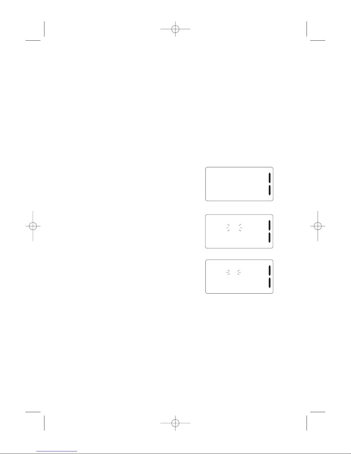
Sending a Distress Call
Important: You must set a user MMSI before
you can send a Distress call.
Please see page 60 to set the
MMSI.
This feature lets you transmit a Distress call.
1. To transmit a Distress call, flip up the
button cover then press and hold
DISTRESS for 5 seconds. The
following screen appears.
2. Select
SEND to confirm the Distress
call or CANCEL to cancel it. If you
select CANCEL, the display returns to
the channel display screen.
DISTRESS
SEND
CANCEL
3. Press the PUSH – SEL knob to send
the Distress call.
The radio transmits the Distress call
then waits for an acknowledgement
signal for about 210 - 270 seconds.
After the Distress call has been sent,
the Distress alert sounds every other
second. The radio also "shadowwatches" for a transmission between
CH16 and CH70 until an
acknowledgement signal is received
from the Coast Guard shore station.
4. To cancel the Distress call, press the
PUSH – SEL knob.
5. When the
VHF600 receives a Distress
call, the following screen appears. The
Distress call is repeated until an
acknowledgement is received from the
Coast Guard shore station.
Note: If the VHF600 receives a Distress call, it appears on the
display and the radio sounds an emergency alert. The name of
the vessel that sent the Distress call is displayed if it is a name
registered in the directory. Otherwise, the vessel’s MMSI is
displayed. Latitude, longitude, and time information also appear
if a GPS receiver is installed in the vessel that sent the
Distress call.
DISTRESS
KENT NEWMAN
35±40.610 N
139±46.564 E
DISTRESS
012345678
35±40.610 N
139±46.564 E
DISTRESS
KENT NEWMAN
NO POSITION
DISTRESS ACK
WAITING
CANCEL
VHF600_UT921ZH 5/28/04 4:24 PM Page 21
 Loading...