

West Marine 7865645 Instruction Manual
FRANÇAIS
Water Pressure Pump
2.4
Instruction Manual
Manuel d’instruction • Manual de instrucción

2
Recreational Craft Directive 94/25/EEC
ISO 8849: 1990/Electrical operated bilge pumps
ISO 8846: 1990/Electrical devices - Protection against ignition of surrounding flammable gases
ISO 10133: 1994/Electrical systems - Extra low-voltage DC installations
Electromagnetic Compatibility Directive 89/336/EEC
EN55014: 1993/Radio Disturbance
Made in the USA
English 3
Français 7
Español 11
Contents • Contenu • Contenido

3
Model 7865645 Water Pressure Pump 2.4
12V DC five chamber positive displacement diaphragm pump.
Typical applications
This pump is the ideal choice for pressurizing water
in a closed system such as that found in a boat or
in a recreational vehicle.
It can easily build the pressure required for a
pressurized water supply system.
Features
• Quiet operation
• Smooth flowing
• Self priming
• Integrated pressure switch turns pump on and off
automatically when tap is opened and closed
• Dry running without damage
• Low power consumption
• Quick disconnect fittings
Working principle
As the pump runs, pressure builds until reaching
2.8 bar/41 psi. At this point, the integrated pressure
switch automatically shuts the pump off.
The pump is equipped with positively checking
outlet valves which ensure that the pressure is
maintained after the pump shuts off.
When water is demanded (at the faucet, shower,
etc.) the pressure decreases. After a moderate
drop in pressure, the integrated pressure switch
automatically turns the pump back on.
Due to it’s durable construction and thoughtful design, the pump will provide many years of service.
Important! The pressure setting of this pump is
made at the factory. Warranty invalidated by
pressure switch interference.
Specifications
Body: Polypropylene
Valve housing: Polyamide
Valves: EPDM
Diaphragm: Santoprene
Connection: ISO228/1-G
3/8" NPT, 1/2" (13mm)
hose and 1/2" NPT,
3/4" (19mm) hose
Liquid temperature: Max. +120°F (+50°C)
Fasteners: Stainless steel
Max. suction lift: 6.5 ft (2m)
Cut in pressure: 1.7 Bar/25 psi
Cut-off pressure: 2.8 Bar/41 psi
Duty cycle: Intermittent,
max 20 min
Motor: 87W, 12V DC
with built in
thermal protection
Weight: 3.5 lb (1.6kg)
The motor and switch are ignition protected
according to ISO 8846 (Small craft – Electrical
devices – Protection against ignition of surrounding
flammable gases).
Pressure and capacity data
Based on water at 68°F (+20°C) and at full voltage
of the motor.
Amperage
Pressure Flow draw
Bar kPa Psi L/min GPM 12V
0 0 0 9.4 2.4 2.5A
0.4 40 5.8 8.8 2.3 3.3A
0.8 80 11.6 8.1 2.1 4.0A
1.2 120 17.4 7.3 1.9 4.6A
1.6 160 23.2 6.7 1.8 5.2A
2.0 200 29 5.8 1.5 5.8A
2.4 240 34.8 4.9 1.3 6.4A
2.8 280 40.6 4.1 1.1 6.9A
Fuse required: 10A
ENGLISH
4
Installation
Locate the pump in a dry location.
1. If the pump is mounted vertically, the motor shall
face up.
2. Mark screw positions and drill pilot holes
(see drilling template page 16).
3. Mount the pump using stainless steel screws
taking care not to over compress the vibration
dampening rubber feet.
4. Reinforced, high-pressure flexible tubing is
recommended. If rigid pipe is used, a length
(minimum 9"/225 mm) of flexible tubing shall be
installed between the pump and the rigid pipe.
This will address noise and/or damage caused by
vibration transmitted to rigid pipe.
5. Use stainless steel hose clamps to secure tubing
to quick disconnect fittings and other hose barbs
in the system.
NOTE: The strainer must be installed in line before
the pump intake, to prevent debris from entering
pump and interfering with proper functioning
of valves.
Electrical installation
1. The pump must be installed according to SS-EN
ISO 10133 (Small craft – Electrical system –
Extra low voltage DC installation for continous
current). Note: The fuse must be ignition
protected.
2. The motor is equipped with built in thermal
protection to prevent the motor from overheating.
The protection is automatically restored when the
motor is cooled.
3. If the pump is connected with separate earth
lead, this should be yellow/green and connected
to the motor base.
4. See the wiring table for correct installation.
Negative wire must be black. Choose wire size in
accordance with total wire length.
5. The wire connections must be sealed with a
marine sealant.
NOTE: Before installation with electrical control
systems, check that equipment to be used is of
sufficient rated capacity to accept amperage draw
of motor. Low voltage will cause motor to overheat.
Maintenance
The system shall be periodically sanitized using
the following procedure:
1. Fill the tank with a solution of household bleach
and potable watern .03 oz. (1ml) bleach to
32 oz. (1 L) water.
2. Open all faucets and run until water flowing
smells of bleach.
3. Close all faucets.
4. Drain solution from tank.
5. Refill tank with potable water.
6. Open all faucets and run until bleach has
been purged.
Max wire
Wire size length* in m
18 GA (1.0 mm2) 11.9
16 GA (1.5 mm2) 17.9
14 GA (2.5 mm2) 29.8
* The wire length is the total distance from the
battery to the pump and back to the battery.
It is recommended to use a relay with a light
wire from main cable to switch to shorten the
main leaders.
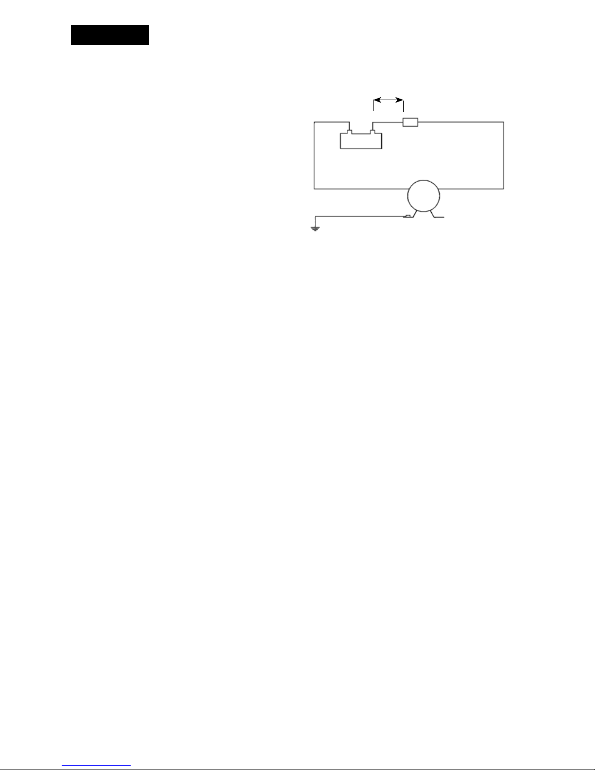
Wiring dimensions
(based on 10% voltage drop)
Other electrical devices, e.g. switch, circuit breaker,
must be installed between the pump and the
positive (+) lead on the battery (on the red wire).
Wiring table
Pump
Terminal
fuse
Max 8" (0.2m)
Red
Black
Green/yellow
+
–
ENGLISH

5
There’s nothing more important to us than customer satisfaction.
If you have any questions or your purchase does not meet your
expectations, please do one of the following:
• Contact your local West Marine store
• Call
1-800-BOATING
• Contact us at www.westmarine.com
Start-up procedure
After pump installation, the system can be started
by using the following procedure:
• Fill water tank
• Open one tap
• Turn on pump
• Close tap once water begins flowing
• Open each additional tap until all air has
been purged from system
• Pump will shut off after taps are closed
and pressure builds to the set point of the
pressure switch
Self-priming
Pump is self-priming up to 6 ft (2m). Intake lines
must be air-tight to ensure self-priming.
Dry running
Pump will not be damaged by shorter period
of dry running. It will, however, unnecessarily
reduce your battery power.
CAUTION: Do not use pump for any liquids other
than fresh water and sea water.
Temperature
Max liquid temperature: +120°F (+50°C)
Max ambient temperature: +140°F (+60°C)
Winterizing
If water is not drained from the system during
freezing temperatures, damage is likely to be
sustained in the plumbing and in the pump. To
prevent damage follow the instructions below:
1. Drain water storage tank.
2. Open all taps.
3. Run pump until remaining water is expelled.
4. Disconnect inlet and outlet tubes.
5. Run pump briefly to confirm that
water has been expelled.
6. Taps shall remain open and pump fittings shall
remain disconnected until temperatures are
above freezing.
Never start a frozen pump. Even if it is drained
it might contain a small amount of frozen water
that locks the rotor.
Accessory
Model 7923667 Universal Strainer
ENGLISH
 Loading...