

Westinghouse WBE4500SARH, WBE4500SALH, WBE4500WALH, WFB4204WA, WTB4600SALH Installation Guide
...Page 1

WTB4600, KTM4602, WTB5400, KTM5402,
WBE4500, KBM4502,
WFB4204, WRB5004
IK008 Integration kit
WBE5300, KBM5302,
Installation manualRefrigeration
Page 2

2 electrolux.com.au
CONGRATULATIONS
Congratulations and thank you for choosing our integration
kit. Before you install the integration kit, we recommend
that you read through the entire installation manual.
To avoid the risks that are always present when you install
an electrical appliance, it is important that the integration
kit and appliance are installed correctly. Please read the
safety instructions in this installation manual as well as the
appliance’s user manual to carefully to avoid misuse
and hazards.
We recommend that you keep this instruction booklet
for future reference and pass it on to any future owners.
After unpacking the integration kit, please check it is not
damaged. If in doubt, do not use the integration kit but
contact your local Electrolux Customer Care Centre.
BEFORE YOU CALL
Please ensure you read the instruction manual fully before
you call for service, or a full service fee could be applicable.
INFORMATION ON DISPOSAL
FOR USERS
ENVIRONMENT!
• Most of the packaging materials are
recyclable. Please dispose of these materials
through your local recycling depot or by
placing them in appropriate collection
containers.
• If you wish to discard this product, please
contact your local authorities and ask for the
correct method of disposal.
CONTENTS
General warnings ....................................................2
Refrigerator integration kit items ..............................3
Cupboard dimensions ..............................................4
Installation of 120˚ hinge ..........................................7
Preparation ...............................................................7
Attaching the rear rollers ..........................................8
Attaching top hinge bracket .....................................9
Attaching slide-housing to refrigerator doors.........10
Placing refrigerator in cupboard .............................11
Refrigerator alignment ............................................12
Securing refrigerator in cupboard ..........................13
Attaching slide-bar to cupboard door ....................13
Notes ......................................................................15
GENERAL WARNINGS
Please read the user manual carefully and store in a handy
place for later reference. Pass the user manual on to
possible new owners of the appliance.
NOTE: We strongly recommend that a professional
builder/cabinet maker builds this unit into required
cabinetry prior to finished installation in customer’s
kitchen. Electrolux cannot take responsibility for
any installation issues when customer retrofits
this product into cabinetry. Cabinet door height
built in excess of refrigerator door height will be
unsupported and risk bowing.
NOTE: Please refer to your Appliance User Manual for
warnings relating to the appliance.
SYMBOLS
WARNING!
This symbol indicates information concerning your
personal safety
CAUTION!
This symbol indicates information on how to avoid
damaging the refrigerator
IMPORTANT!
This symbol indicates tips and information about
use of the refrigerator
ENVIRONMENT!
This symbol indicates tips and information about
economical and ecological use of the refrigerator
Page 3
DESCRIPTION
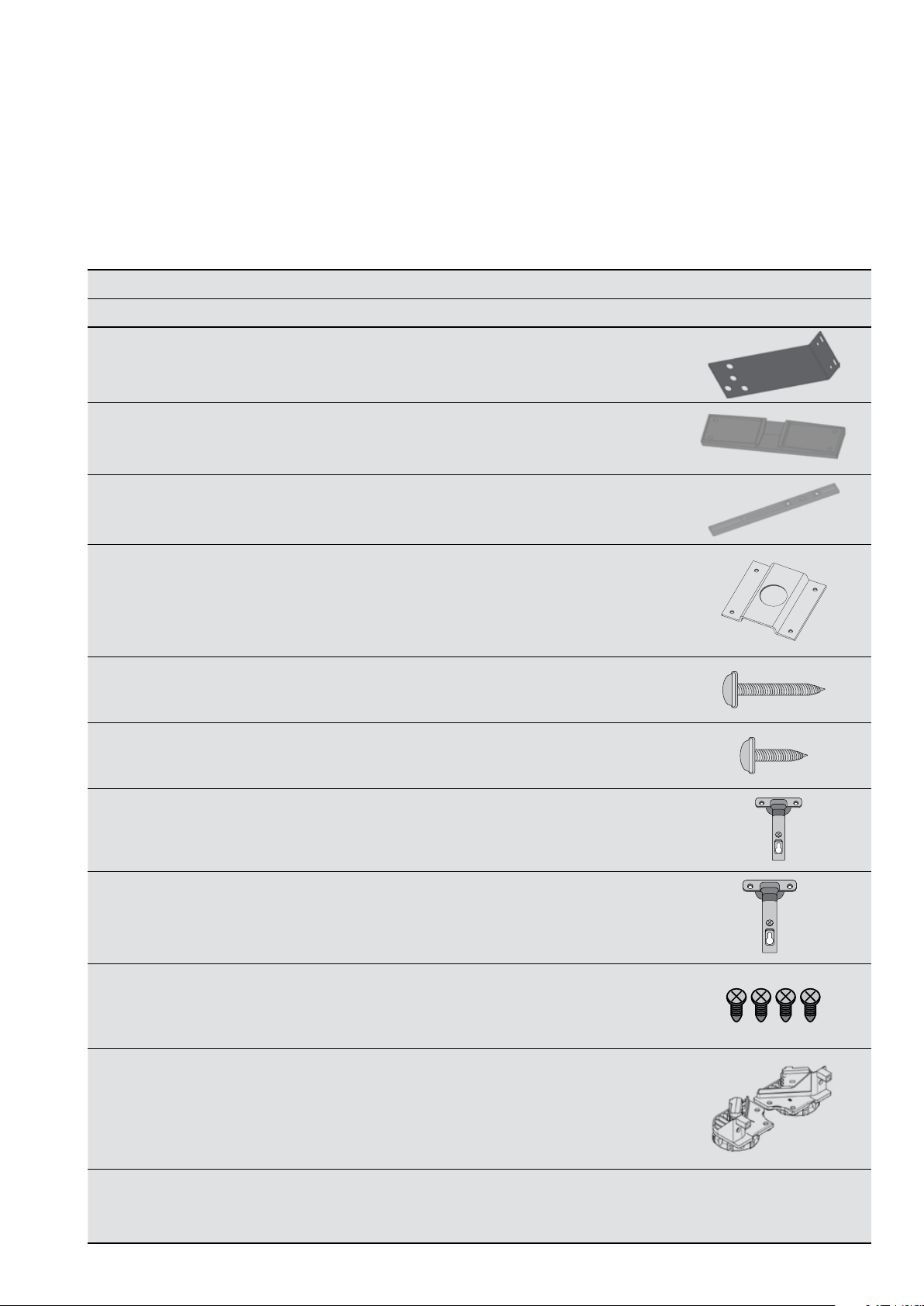
REFRIGERATOR INTEGRATION KIT ITEMS
Because this kit is common to a variety of models, you need to select the items required to suit your model. The items
required for the models covered in this instruction booklet are shown below.
Those items not required on your particular model should be discarded.
Item Quantity in kit Quantity required Description
Two door model Single door model
3
Top hinge bracket
PNº A02986001
Slide-housing
PNº A04098601
Slide-bar
PNº A04098501
Location bracket
front footing
PNº A02986101
(Top Freezer
models only)
Refrigerator screws
PNº A04120701
(74124 9 )
Cupboard screws
PNº A04120801
(144 9 422)
1 1 1
2 2 1
2 2 1
2 2 2
8 8 4
12 12 8
120º hinge
PNº A0 4120 901
(1457832)
Mounting plate
for hinge
PNº A0 41210 01
(14 58 2 11)
Self tapping
wood screws
PN º A 04121101
(145 8 212)
Service Kit Rear
Rollers
PNº A04078201
Installation
Instruction Sheet
PN º A0463 3101
5 5 (3+2) 3
5 5 (3+2) 3
20 20 12
1 1 1
1 1 1
Page 4

4 electrolux.com.au
DIMENSIONS
CUPBOARD DIMENSIONS
IMPORTANT!
Pages 4, 5, 6, and 7 should be given to the person responsible for cupboard design and construction.
The cupboard dimensions required for each model are shown on page 5, 6 & 7.
1. All sizes are internal and measured in millimetres.
2. It is important to ensure that the correct cupboard sizes are used to ensure adequate air flow around the refrigerator.
3. Cupboard hinges should be a 120° opening type. (Use hinges supplied).
4. Three hinges should be used on each cupboard door higher than 1000mm.
5. Ensure the refrigerator is not connected to a power supply whilst installation takes place.
6. Each operation should be carried out in the sequence specified in this instruction sheet.
NOTE: All sizes are internal and in millimetres.
Model
2 door top freezer models
WTB4600, WTB4604,
KTM4602
WTB5400, WTB5404,
KTM5402
2 door bottom freezer models
WBE4500, KBM4502
WBE5300, KBM5302
single door models
WFB4204
WRB5004
Step 1
Dim ‘A’
(mm) min.
1820 780 799 1217 600 241 395
1820 780 896 1217 600 278 495
1820
1820
1820
1820
Dim ‘B’
(mm)
780
780
780
780
Dim ‘C’
(mm)
795
895
799
799
Dim ‘D’*
(mm)
702
702
–
–
Dim ‘E’
(mm)
600
600
500
600
Dim ‘G’
(mm)
241
278
219
241
Dim ‘H’
(mm)
395
495
300
395
Dim ‘I’*
(mm)
Please
use the
calculation
below to
measure
Dimension
‘I’ for your
specific
model.
Measure and confirm Dimension ‘A’.
Step 2
To calculate Dimension ‘I’ use the equation below.
Dim ‘I’ = Dim ‘A’ - (Dim ‘D’ + 5mm) mm
Step 3
* Add cabinetry thickness to Dimension ‘D’ and
Dimension ‘I’ for final measurement before construction.
Page 5
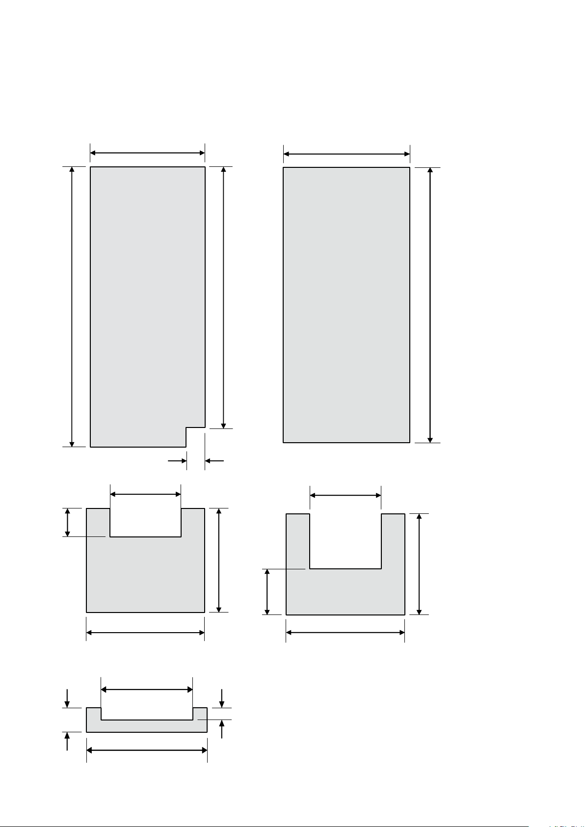
NOTE: All sizes are internal and measured in millimetres.
Dim B
Dim A + Skirting height + board thickness
Dim C + 2x Board
Skirting
height
For ‘lettered’ dimensions refer to the table on page 4.
5
thickness
Panel A
(sides)
Dim A + Skirting height
100mm
Dim E
Dim A
Panel B
(back)
Dim H
80mm
Panel C
(top)
Dim C
Dim E
Dim C + 2x Board
thickness
Dim B
50mm
130mm
Dim B
Panel D
(bottom)
Dim C
Page 6

6 electrolux.com.au
DIMENSIONS (CONTINUED)
Clearances
When installed the
refrigerator needs to have
adequate air ventilation. It is
important to ensure there
is good airflow from the
front to underneath and up
the rear to the top of the
cabinet (see diagrams).
Airflow
Front airflow cut-out
NOTE: A decorative grill can be fitted so long as it does
not obstruct airflow and is removable for cleaning.
When positioned in a corner the clearance of Dim G on
the hinge side of the cabinet will allow the doors to be
opened enough to enable the removal of the crisper bins.
Dim C
120º
Dim G
NOTE: Use the 120° hinges supplied with the kit to attach
the cupboard door to the cupboard.
Attach the hinge to the door to ensure that door can have
maximum opening, i.e. the door edge should not hit the
cabinet when the door is fully open.
Dim E
Front airflow cut-out
Bottom rear airflow cut-out
Bottom rear airflow cut-out
Top rear airflow cut-out
80mm
Dim E
Dim E
50mm
130mm
Cabinet construction
(top mount cupboard shown below)
5mm gap
between doors
Dim I
Dim D
NOTE: If Dim D is larger than 1000mm in height, 3 hins are
required to attach the cupboard door to the cupboard.
If Dim D is smaller than 1000mm in height, 2 hinges are
required/sufficient.
Page 7

INSTALLATION
7
INSTALLATION OF 120˚ HINGE
Please follow the instructions below to install the
120º hinge.
mounting plate
120º hinge
Attach mounting plate with 120º hinge and tighten
the screw.
120º hinge
screw
Preparation
1. Unpack refrigerator, removing foam packing.
2. Lay the refrigerator down on its back on a piece of
soft packing material. Use caution and two people
while laying the appliance down.
3. Remove top door stopper if fitted (Figure 1).
4. Place adjustable rollers in the fully retracted position
by screwing height adjusting screw fully anticlockwise (Figure 2). Do not remove the adjusting nut
completely.
5. Stand upright.
Figure 1
mounting plate
Use screws provided with the hinge to attach the
cupboard door to the cupboard.
screws
Use 120º hinge to attach the cupboard door to the cabinet.
cabinet
cupboard door
Figure 2
Plastic roller nut
37mm
This dimension is typically 37mm
(from centre line of mounting plate
to the cupboard cabinet edge)
Page 8

8 electrolux.com.au
INSTALLATION (CONTINUED)
ATTACHING THE REAR ROLLERS
A set of adjustable back feet/rollers is provided in the kit.
These are required to ensure that the product is levelled
correctly, failure to fit these may result in the poor operation
of door opening.
1. Temporarily unfasten the screws holding the
evaporator tray.
2. Fit the right assembly.
Once fitted turn the adjusting nut on each roller assembly
anti-clockwise three full turns, this will raise the cabinet
at the rear by approximately 12mm (ensure that the nut is
completely wound up before turning).
Then secure the nut and roller assembly in place with tape
(this will prevent the roller assembly from falling out when
the refrigerator is place in the cupboard).
3. Repeat for the left hand side.
Page 9

9
ATTACHING THE TOP HINGE
BRACKET
1. Remove top hinge cover (Figure 3), cover clips off.
2. Remove the three (3) top hinge screws.
3. Elevate hinge.
4. Slide the top hinge bracket into position below
the hinge.
5. Re-attach hinge and screws ensuring that refrigerator
door is still correctly positioned.
IMPORTANT!
You must ensure that the refrigerator door is:
• Parallel with sides and top of cabinet.
• The gap between the door and cabinet is
typically 12mm allowing the door gasket to
act correctly (Figure 4).
NOTE: Ensure the gasket acts correctly, i.e. doesn’t make a
noise or leave gaps when the door is closed.
6. Recap hinge cover into position.
Figure 4
12mm
Figure 3
1
2
3
Top hinge bracket fitted.
Top hinge cover
6
5
Top hinge
bracket
5
4
Page 10

10 electrolux.com.au
INSTALLATION (CONTINUED)
ATTACHING SLIDE-HOUSING TO
REFRIGERATOR DOORS
1. Ensure slide-housing is positioned squarely
as shown.
2. Ensure that the slide-housing is positioned on the
door as shown in the diagrams.
NOTE: The slide-housing ‘protruding edge’ side must
always be closest to the door handle side (diagram right).
100mm
235mm
235mm
235mm
235mm
slide housing
protuding edge
100mm
door handle
360mm
100mm
100mm
2 door bottom freezer 2 door top freezer single door
...and secure with tape.
Two door Single door
Page 11

NOTE: For single door models, the door handle must be
completely removed to provide clearance to the cupboard
door and the resulting handle mounting holes hidden with
a cover. Installer must use a tape or plastic cover that suits
the installation appearance (not supplied).
3. While the slide-housing is taped in position, punch a
small hole in the refrigerator door skin corresponding
to the four (4) holes in the housing (Figure 5).
4. The holes should be punched, not drilled, to ensure
the maximum thread can be formed in the metal.
5. Screw four (4) refrigerator screws into the holes
securing the housing in place. The refrigerator screws
are supplied in kit (Figure 6).
If you have a two door refrigerator, repeat this process for
the other door.
Figure 5 Figure 6
11
1
2
3
4
Placing refrigerator in cupboard
1. Ensure cupboard is level and square.
2. Put refrigerator into cupboard. Use caution and
two people if necessary.
3. Insert slide bars into slide-housings (Figure 7).
NOTE: Ensure the refrigerator is level in the cupboard.
Raise the front of the refrigerator by using the height
adjusting screws.
1
2
3
4
Figure 7
Page 12

12 electrolux.com.au
INSTALLATION (CONTINUED)
REFRIGERATOR ALIGNMENT
Position the refrigerator in the cupboard so that:
1. Top hinge bracket is against cupboard wall (Figure 8).
2. Front of refrigerator cabinet (with doors open) is
parallel to and approximately 100mm from the front of
the cupboard (Figure 9).
3. Position bottom location brackets as shown (Figures
9 & 9a). Fit foot in appropriate hole as shown and
level refrigerator. (Figure 10)
NOTE: Do not screw in place yet.
NOTE: The front adjustable rollers may need raising (rotate
anti-clockwise when viewed from above) to achieve this.
Figure 8
85mm
Fridge
Figure 9a - Hinge side
Figure 10
Top Hinge Bracket fitted – note the space between
the cupboard and the side of the refrigerator is to be
approximately 85mm.
Figure 9
100mm
Height
adjustable
roller
Stability foot
4. Slowly close the cupboard door (pushing the
refrigerator back) until it is slightly ajar, i.e. with a gap
of about 4mm (Figure 11).
You may have to reposition the refrigerator back or forward
until the 4mm gap is obtained. Ensure that the refrigerator
remains parallel as you do this. Once you have the correct
gap, proceed to the next step.
Figu r e 11
4mm hinge gap
NOTE: The gap is left to ensure the refrigerator door will be
allowed to close fully for a good gasket seal.
Page 13

13
SECURING THE REFRIGERATOR IN
THE CUPBOARD
NOTE: When attaching all screws to cupboard, first drill
a 2mm pilot hole in the correct position. This will allow
easy hand insertion of self tapping screw.
Now that the refrigerator is correctly positioned:
1. Screw in top hinge bracket to the cupboard wall
using 4 cupboard screws provided. This will secure
the top of the refrigerator (Figure 12).
2. Screw down both foot brackets to cupboard floor
with 2 cupboard screws. This will secure the bottom
of the refrigerator (Figure 13.)
Figure 12
Fridge
ATTACHING SLIDE-BAR TO THE
CUPBOARD DOOR
1. Fully open cupboard door (120°).
2. Open refrigerator door until it rests against the
cupboard door.
3. Position slide-bar in slide-housing so that all three
holes are visible when both doors are fully open
(120°). This position is typically 230mm from the edge
of the slide housing (Figure 14).
Figure 14
120º
cupboard door
refrigerator door
Figure 13
125mm
slide bar
Whilst slide-bar is still in housing:
4. Rotate slide-bar to uppermost alignment, mark a line
on cupboard door (Figure 15).
Figure 15
Page 14

14 electrolux.com.au
INSTALLATION (CONTINUED)
5. Rotate slide-bar to lower alignment, mark a line on
cupboard door (Figure 16).
Figure 16
6. Remove slide-bar and draw line to indicate central
alignment (Figure 17).
Fi g u r e 17
7. Replace slide-bar and align to centre line marked in
previous operation (Figure 18).
Figure 18
Page 15

NOTES
15
Page 16

Electrolux Home Products Australia
telephone: 1300 363 640
fax: 1800 350 067
email: customercare@electrolux.com.au
web: electrolux.com.au
Electrolux Home Products New Zealand
telephone: 0800 436 245
fax: 0800 225 088
email: customercare@electrolux.co.nz
web: electrolux.co.nz
To add a touch of
professional inspiration
to your home,
visit electrolux.com.au
or electrolux.co.nz
shop.electrolux.com.au
P/No. A04633101
© 2015 Electrolux Home Products Pty Ltd.
ABN 51 004 762 341
EMAN_IK008_Sep15
 Loading...