

Page 1
Universal Cooker Hood Installation and Operation Manual
The instructions in this manual are for cooker hood models:
WRJ903U, WRJ600U, WRJ603U, WRJ611U, WRJ900U,WRJ911U, RHN6, RHN9, RFD602W, RFD602S, RFD902W, RFD902S
These cooker hoods are domestic appliances which have been manufactured and tested to comply with Australian and New Zealand
Standard AS/NZS 3350.2.31.
These appliances are intended to be used in household and similar applications such as:
-Farm Houses
-By clients in hotels, motels and other residential type environments
-Bed and breakfast type environments
Safety Warning
This appliance is not intended for use by persons (including children) with reduced physical, sensory or mental capabilities, or lack of experience
and knowledge, unless they have been given supervision or insruction concerning use of the appliance by a person responsible for their safety.
Children should be supervised to ensure they do not play with the appliance.
Ensure the cooker hood is switched off before carrying out maintenance, to avoid any possibility of electric shock.
Do not under the cooker hood.
This cooker hood is not recommended for barbeques.
Exhaust air must not be discharged into a wall cavity, unless the cavity is designed for the purpose.
There must be adequate ventilation of the room when the cooker hood is used at the same time as appliances burning gas or other fuels.
Always cover lit gas burners with pots or pans when the cooker hood is in use.
Always switch off gas burners before you remove pots or pans.
CAUTION: Accessible parts may become hot when used with cooking appliance.
Cleaning
. Do not use oven cleaners or other abrasive
materials.
Electrical Connection
Check that the mains voltage matches with the voltage on the data plate inside the cooker hood.
Check that the installation complies with standards of local gas and electricity authorities.
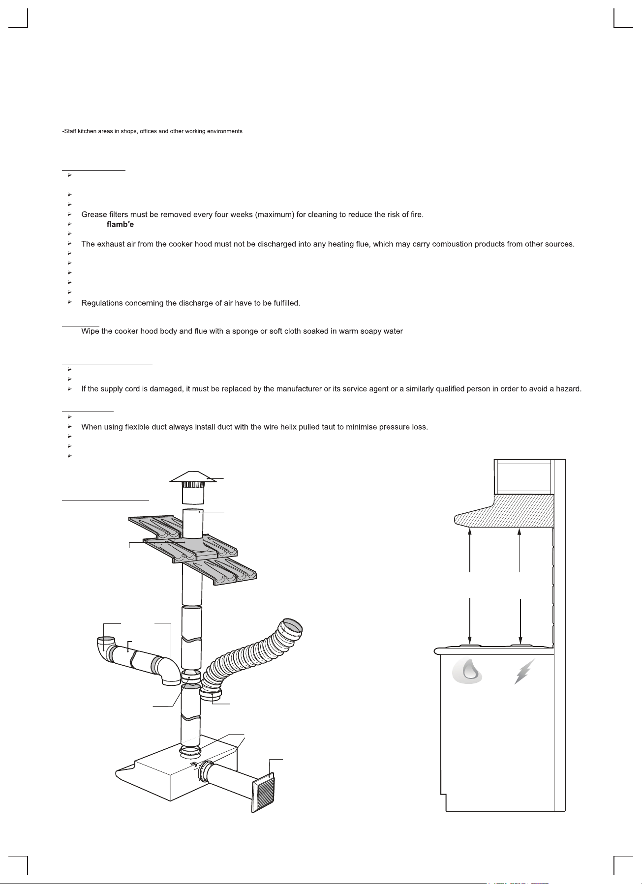
Accessories
Use 125mm round exhaust ducting for best performance.
Try to keep exhaust duct short and straight.
Keep bends in the exhaust duct to a minimum.
Do not reduce the size or restrict exhaust duct.
Roof cowl
AR125RC
Ducting Accessories
Flue
1200mm length
AR125F
Flashing
Not Supplied
90 bend
AR125B
Flue
600650
(MINIMUM)(MINIMUM)
Flue joiner
-plain AR125FJ
-damper
AR125FJD
Alternative flue connection
1 metre flexible duct with joiners
AR125FD
Flue collar
1 supplied
with hood
Wall vent
(includes 400mm of flue)
AR125WV
GAS
ELECTRIC
Page 2
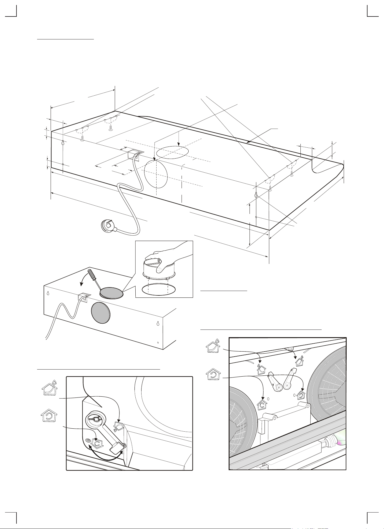
Stainless Steel Models
Before installing the cooker hood, remove all protective plastic covering from stainless steel surfaces.
Use at least 4 screws (not provided) and the mounting holes provided to securely mount the cooker hood. Make sure that the cooker hood is level
and free from twist.
Warning: Failure to install the screws or xing device in accordance with these instructions may result in electrical hazards.
Recommended
Top Fixing Points
(use 2 from each end)
300
Top and Rear Exhaust Outlets
25
25
30
143
30
105
60
c
L
90cm wide models
nominal width 898
60cm wide models
nominal width 598
100
c
L
79
160
Ducted installation
Select required exhaust outlet, remove hole
plug and snap t ue exhaust collar.
Air Recirculating Outlet
25
35
500
Recommended
Rear Fixing Points (4)
The maximum space between
the wall and screw cap is 5mm
Setting of circulation air doors - dual fan models
EXHAUST
Setting of circulation air door - single fan models
RECIRCULATE
EXHAUST
RECIRCULATE
IMPORTANT: SET CIRCULATING MODES BEFORE INSTALLING THE HOLE PLUGS.
Page 3

Cooker Hood Operation
IMPORTANT: The Edison Screw lamps may have come loose during transportation. Ensure that lamps are tightened rmly into the socket
before power is applied.
Best results are obtained by using a low speed for normal conditions and a high speed when odours are more concentrated. Turn the hood on a few
minutes before you start cooking. It should by left on after cooking for about 15 minutes or until all odours have disappeared.
Slide switch controls Press button switch controls
Light switch:
Extractor fan switch:
Slide position I:
Slide position II:
Slide position III:
This switch is used to turn the light tted in the
hood on and off.
Used to select fan speeds
Fan speed Lo.
Fan speed Med.
Fan speed High.
Light switch: Depress light button to turn light ON. Press light button
to turn light OFF.
Extractor fan switch interlocked switching: Select a fan
speed, depress button to turn fan ON. Press button (O) to turn fan
OFF.
Replacing lamps:
Ensure the appliance is switched off before carrying out maintenance,
to avoid any possibility of electric shock. Remove grease lter to
replace lamp. Replace with 40W (maximum) E14 candle lamp.
Maintenance:
Clean grease lters every three to four weeks maximum. Greasy lters
are a re risk.
Remove the grease lters, soak and agitate in hot soapy water.
Rinse, drain and shake well before replacing lters.
Do not use oven cleaners or other caustic materials.
Recirculating accessory:
Optional carbon lter ARCFD for recirculating mode only.
Page 4

Part Number: 0342 001 592, Issue C
 Loading...