

Westinghouse WHC7500E, WHC5500, WHC6500E, WHC6000S Owner's Manual

California
Proposition 65 Warning
The engine exhaust from this product
contains chemicals known to the state of
California to cause cancer, birth defects
or other reproductive harm.
Proposition 65 Warning
Certain components in this product and its
related accessories contain chemicals
known to the state of California to cause
cancer, birth defects or other reproductive
harm. Wash hands after handling.
California
DISCLAIMERS:
All information, illustrations and specifications in this manual are based on the latest information available at
the time of publishing. The illustrations used in this manual are intended as representative reference views only.
Moreover, because of our continuous product improvement policy, we may modify information, illustrations and/or
specifications to explain and/or exemplify a product, service or maintenance improvement. We reserve the right to
make any change at any time without notice. Some images may vary depending upon which model is shown.
ALL RIGHTS RESERVED:
No part of this publication may be reproduced or used in any form by any means – graphic, electronic or
mechanical, including photocopying, recording, taping or information storage and retrieval systems – without the
written permission of Westpro Power Systems, LLC.
2
CONGRATULATIONS ON OWNING A WESTINGHOUSE
GENERATOR
!
DANGER
This manual contains important instructions for operating this generator. For your safety and
!
For Your Records:
Date of Purchase: Generator Model Number:
Purchased from Store/Dealer: Generator Serial Number:
Purchase Receipt: (retain your purchase receipt to ensure trouble-free warranty coverage)
Product Registration
To ensure trouble-free warranty coverage, it is important you register your Westinghouse generator. You can register
your generator by either:
1. Filling in the product registration form below and mailing to:
2. Registering your product online at www.westpropower.com
To register your generator you will need to locate the following information:
the safety of others, be sure to read this manual thoroughly before operating the generator.
Failure to properly follow all instructions and precautions can cause you and others to be
seriously hurt or killed.
Product Registration
Westpro Power Systems, LLC
W237 N2889 Woodgate Road, Unit B
Pewaukee, WI 53072
Product Registration Form
PERSONAL INFORMATION GENERATOR INFORMATION
First Name: Model Number:
Last Name: Serial Number:
Street Address: Date Purchased:
Street Address: Purchased From:
City, State, ZIP:
Country:
Phone Number:
E-Mail:


TABLE OF CONTENTS
CONGRATULATIONS ON OWNING A WESTINGHOUSE GENERATOR .........................................................3
For Your Records: .........................................................................................................................................3
Product Registration .....................................................................................................................................3
Product Registration Form ............................................................................................................................3
SAFETY ....................................................................................................................................................................7
SAFETY DEFINITIONS ......................................................................................................................................7
SAFETY SYMBOL DEFINITIONS ......................................................................................................................7
GENERAL SAFETY RULES ...............................................................................................................................8
SAFETY LABELS AND DECALS .....................................................................................................................10
UNPACKING ...........................................................................................................................................................12
UNPACKING THE GENERATOR ......................................................................................................................12
WHEEL KIT ACCESSORIES BOX ...................................................................................................................12
Components: ..............................................................................................................................................12
ASSEMBLY .............................................................................................................................................................13
ASSEMBLY .......................................................................................................................................................13
INSTALLING THE BATTERY (ELECTRIC START GENERATORS ONLY) .......................................................15
FEATURES .............................................................................................................................................................16
GENERAL GENERATOR FEATURES ..............................................................................................................16
CONTROL PANEL FEATURES ........................................................................................................................18
OPERATION ...........................................................................................................................................................19
BEFORE STARTING THE GENERATOR .........................................................................................................19
ADDING / CHECKING ENGINE FLUIDS AND FUEL .......................................................................................21
Checking and / or Adding Engine Oil ..........................................................................................................21
Adding Gasoline to the Fuel Tank ...............................................................................................................21
STARTING THE GENERATOR .........................................................................................................................22
Manually Starting a Generator ...................................................................................................................22
Starting an Electric Start Generator ...........................................................................................................24
STOPPING THE GENERATOR ........................................................................................................................25
Normal Operation .......................................................................................................................................25
During an Emergency .................................................................................................................................25
MAINTENANCE ......................................................................................................................................................26
MAINTENANCE ................................................................................................................................................26
Maintenance Schedule ...............................................................................................................................26
ENGINE OIL MAINTENANCE ..........................................................................................................................27
Engine Oil Specification ..............................................................................................................................27
Checking Engine Oil ...................................................................................................................................27
Adding Engine Oil .......................................................................................................................................28
Changing Engine Oil ...................................................................................................................................28
AIR FILTER MAINTENANCE ............................................................................................................................28
Cleaning the Air Filter .................................................................................................................................28
SPARK PLUG MAINTENANCE ........................................................................................................................30
CLEANING THE SPARK ARRESTOR ..............................................................................................................32
CLEANING THE GENERATOR ........................................................................................................................32
BATTERY SERVICE .........................................................................................................................................33
Battery Replacement ..................................................................................................................................33
STORAGE .........................................................................................................................................................34
TROUBLESHOOTING ............................................................................................................................................35
TROUBLESHOOTING ......................................................................................................................................35
5

TABLE OF CONTENTS
This Page Intentionally Left Blank
6
SAFETY
SAFETY DEFINITIONS
The words DANGER, WARNING, CAUTION and
NOTICE are used throughout this manual to highlight
important information. Be certain that the meanings of
these alerts are known to all who work on or near the
equipment.
This safety alert symbol appears
with most safety statements. It
!
Indicates a hazardous situation which, if not
avoided, will result in death or serious injury.
Indicates a hazardous situation which, if not
avoided, could result in death or serious injury.
Indicates a hazardous situation which, if not
avoided, could result in minor or moderate injury.
means attention, become alert, your
safety is involved! Please read and
abide by the message that follows
the safety alert symbol.
!
DANGER
!
WARNING
!
CAUTION
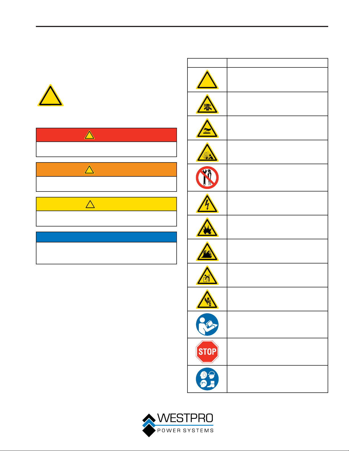
SAFETY SYMBOL
DEFINITIONS
Symbol Description
!
Safety Alert Symbol
Asphyxiation Hazard
Burn Hazard
Burst/Pressure Hazard
Don’t leave tools in the area
Electrical Shock Hazard
Explosion Hazard
NOTICE
Indicates a situation which can cause damage to the
generator, personal property and/or the environment,
or cause the equipment to operate improperly.
OTE:N Indicates a procedure, practice or condition
that should be followed in order for the
generator to function in the manner
intended.
Fire Hazard
Lifting Hazard
Pinch-Point Hazard
Read Manufacturer’s Instructions
Read Safety Messages Before
Proceeding
Wear Personal Protective Equipment
(PPE)
7
SAFETY
GENERAL SAFETY RULES
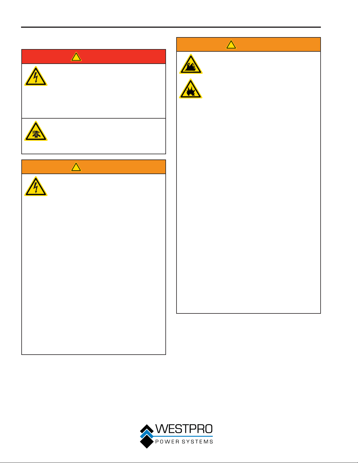
!
DANGER
Never use the generator in a location
that is wet or damp. Never expose the
generator to rain, snow, water spray or
standing water while in use. Protect the
generator from all hazardous weather
conditions. Moisture or ice can cause a
short circuit or other malfunction in the
electrical circuit.
Never operate the generator in an
enclosed area. Engine exhaust
contains carbon monoxide. Only
operate the generator outside and away
from windows, doors and vents.
!
WARNING
Voltage produced by the generator
could result in death or serious injury.
• Never operate the generator in
rain or a floodplain unless proper
precautions are taken to avoid being
subject to rain or a flood.
• Never use worn or damaged
extension cords.
• Always have a licensed electrician
connect the generator to the utility
circuit.
• Never touch an operating generator
if the generator is wet or if you have
wet hands.
• Never operate the generator in highly
conductive areas such as around
metal decking or steel works.
• Always use grounded extension
cords. Always use three-wire or
double-insulated power tools.
• Never touch live terminals or
bare wires while the generator is
operating.
• Be sure the generator is properly
grounded before operating.
!
WARNING
Gasoline and gasoline vapors are
extremely flammable and explosive
under certain conditions.
• Always refuel the generator outdoors,
in a well-ventilated area.
• Never remove the fuel cap with the
engine running.
• Never refuel the generator while
the engine is running. Always turn
engine off and allow the generator to
cool before refueling.
• Only fill fuel tank with gasoline.
• Keep sparks, open flames or other
form of ignition (such as match,
cigarette, static electric source) away
when refueling.
• Never overfill the fuel tank. Leave
room for fuel to expand. Overfilling
the fuel tank can result in a sudden
overflow of gasoline and result in
spilled gasoline coming in contact
with HOT surfaces. Spilled fuel
can ignite. If fuel is spilled on
the generator, wipe up any spills
immediately. Dispose of rag properly.
Allow area of spilled fuel to dry
before operating the generator.
• Wear eye protection while refueling.
• Never use gasoline as a cleaning
agent.
• Store any containers containing
gasoline in a well-ventilated area,
away from any combustibles or
source of ignition.
• Check for fuel leaks after refueling.
Never operate the engine if a fuel leak
is discovered.
8
!
WARNING
Never operate the generator if powered
items overheat, electrical output drops,
there is sparking, flames or smoke
coming from the generator, or if the
receptacles are damaged.
Never use the generator to power
medical support equipment.
!
Always remove any tools or other
service equipment used during
maintenance from the generator before
operating.
NOTICE
Never modify the generator.
Never operate the generator if it vibrates at high
levels, if engine speed changes greatly or if the
engine misfires often.
Always disconnect tools or appliances from the
generator before starting.
SAFETY
9
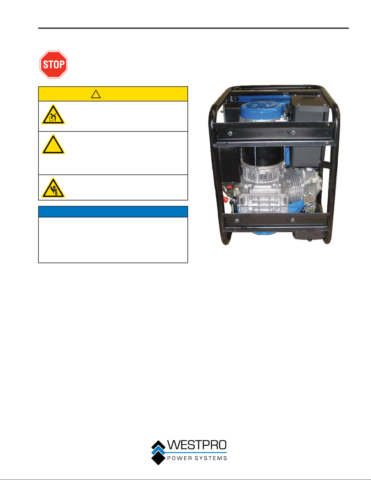
SAFETY
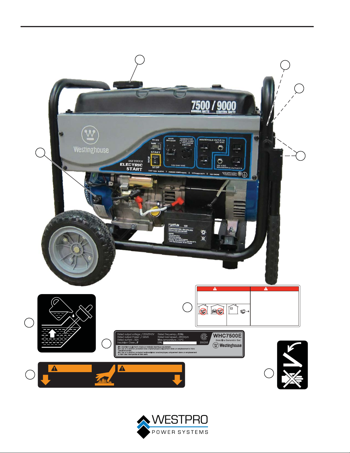
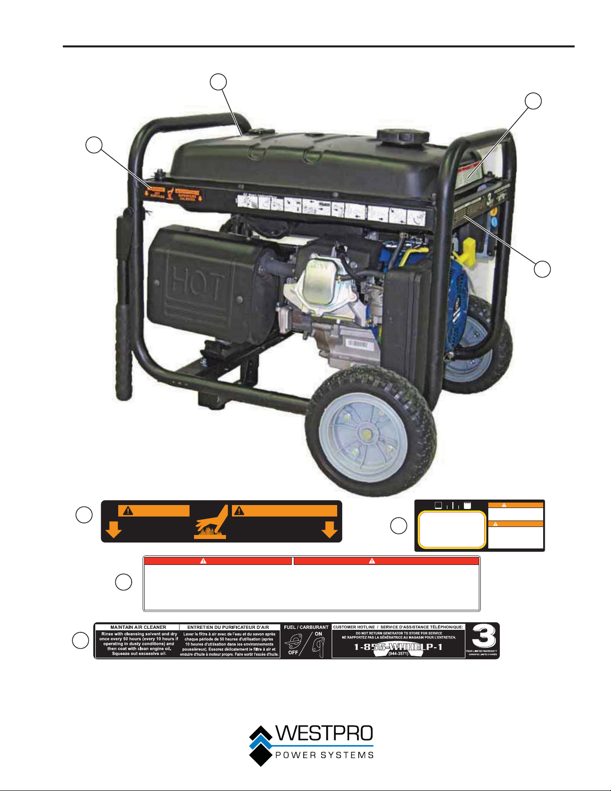
SAFETY LABELS AND DECALS
2
3
4
1
5
10
DANGER
USING A GENERATOR INDOORS
CAN KILL YOU IN MINUTES.
GENERATOR EXHAUST CONTAINS
CARBON MONOXIDE.
THIS IS A POISON YOU CANNOT SEE OR SMELL.
2
NEVER USE INSIDE A
HOME OR GARAGE,
EVEN IF DOORS AND
1
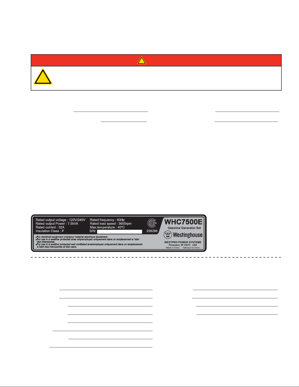
Rated output voltage : 120V/240V Rated frequency : 60Hz
Rated output Power : 7.5kVA Rated load speed : 3600rpm
Rated current : 32A Max.temperature : 40 C
Insulation Class : F S/N: 258286
3
ƽ
For electrical equipment only/pour materiel electrique seulement.
For use in a weather protected area only/employez uniquement dans un emplacement a l'abri
ƽ
des intemperies.
For use in a weather protected well ventilated area/employez uniquement dans un emplacement
ƽ
a l'abri des intemperies et bien aere.
º
WINDOWS ARE OPEN.
ONLY USE OUTSIDE
AND FAR AWAY
FROM WINDOWS,
DOORS, AND VENTS.
WHC7500E
Gasoline GeneratorSet
WESTPRO POWER SYSTEMS
Pewaukee, WI 53072 USA
Made in China Fabriqué en Chine
DANGER
L’UTILISATION D’UNE GÉNÉRATRICE Á
L’INTÉRIEUR PEUT VOUS TUER EN
QUELQUES MINUTES. LES GÉNÉRATRICES
REJETTENT DU MONOXYDE DE CARBONE,
UN GAZ TOXIQUE INVISIBLE ET INODORE.
NE JAMAIS UTILISER LA GÉNÉRATRICE Á
L’INTÉRIEUR D’UNE RESIDENCE OU D’UN
GARAGE MÊME SI LES PORTES ET LES
FENÊTRES SONT OUVERTES.
UTILISER UNIQUEMENT A L’EXTÉRIEUR ET
LOIN DES FENÊTRES, PORTES ET ÉVENTS.
WARNING AVERTISSEMENT
4
HOT
SURFACES
SURFACES
CHAUDES
Figure 1
5
SAFETY
2
3
1
4
1
WARNING AVERTISSEMENT
HOT
SURFACES
▪
ANYONE using the generator must read, understand, and follow all safety and operation
instructions provided in the product manual. Failure to closely follow these instructions can result
in circumstances leading to death, serious injury, and property damage.
tor while engine is running. Gasoline spilled on hot engine parts could ignite. Clean any spilled
gasoline immediately. Before refueling generator, turn the engine OFF and allow engine to cool.
3
▪
NEVER smoke and NEVER allow flames or sparks near the generator or where gasoline is
Generators pose a risk of shock and electrocution, especially if operated in wet or damp
▪
stored.
conditions. Keep generator and the surface it sits on dry at all times.
reach temperatures that could cause serious burns if touched. NEVER touch hot surfaces. Stay
clear from hot exhaust gases.
switch has been installed by a qualified electrician.
▪
NEVER connect to a building’s electrical system unless a transfer
SURFACES
CHAUDES
▪
NEVER refuel genera-
▪
Muffler and engine parts
▪
TOUTE PERSONNE qui utilise la génératrice doit lire, comprendre et respecter toutes les directives de sécurité et de
fonctionnement fournies dans le manuel qui accompagne le produit. Le fait de ne pas respecter attentivement ces directives peut provoquer un décès, des blessures graves et des dommages à la propriété.
trice en carburant pendant que le moteur fonctionne. L’essence renversée sur un moteur chaud pourrait s’enflammer.
Nettoyez immédiatement toute essence renversée. Avant de procéder au ravitaillement de la génératrice en carburant,
assurez-vous de FERMER le moteur et laissez-le refroidir.
d’étincelles là où l’essence est entreposée.
plus particulièrement si elles sont utilisées dans des conditions mouillées ou humides. Assurez-vous que la génératrice
ainsi que la surface sur laquelle elle repose soient toujours sèches.
températures qui pourraient provoquer des brûlures graves au contact. NE touchez JAMAIS à des surfaces chaudes.
Restez éloigné des gaz d’échappement.
teur converteur a été installé par un électricien compétent.
DANGERDANGER
▪
NE JAMAIS fumer et NE JAMAIS permettre de flamme ou
Les génératrices peuvent représenter un risque de choc ou d’électrocution,
▪
▪
NE JAMAIS brancher sur le système électrique d’un édifice sauf si un commuta-
FUEL
2
▪
Les pièces du silencieux et du moteur atteignent des
CUTOUT
▪
NE JAMAIS ravitailler la généra-
WARNING
NEVER FUEL UNIT WITH ENGINE RUNNING.
ALWAYS FUEL UNIT IN WELL VENTILATED AREA.
ALWAYS CLEAN FUEL SPILLS.
ALWAYS ALLOW UNIT TO COOL BEFORE FUELING.
AVERTISSEMENT
NE JAMAIS RAVITAILLER EN CARBURANT
PENDANT QUE LE MOTEUR FONCTIONNE.
RAVITAILLEZ TOUJOURS L’UNITÉ DANS UN
ENDROIT BIEN AÉRÉ.
NETTOYEZ TOUJOURS LES DÉVERSEMENTS
D’HUILE.
LAISSEZ TOUJOURS L’UNITÉ REFROIDIR
AVANT DE LA RAVITAILLER EN CARBURANT.
4
Figure 2
11
UNPACKING
UNPACKING THE
GENERATOR
!
CAUTION
Always have assistance when lifting
the generator. The generator is heavy;
lifting it could cause bodily harm.
Avoid cutting on or near staples to
prevent personal injury.
!
Tools required – box cutter or similar device.
1. Carefully cut the packing tape on top of the carton.
Fold back top flaps to reveal the manual and EZ
2.
Start instructions sitting on top of the unit. Remove
both documents and save them for reference.
3. Remove the Wheel Kit Accessories cardboard box.
4. Carefully cut two sides of the carton to remove the
generator.
WHEEL KIT ACCESSORIES
1
2
4
5
3
BOX
Open the Wheel Kit Accessories box and verify
the contents against the list below. If any parts are
missing, please locate an authorized Westinghouse
Generator dealer at www.westpropower.com or call
1-855-WHHELP1 (1-855-944-3571).
Components:
Wheels (2)
Handles with Grips (2)
Tool Bag (1)
Spark Plug Socket
Wrench (1)
One Liter Bottle of
SAE 10W30 Oil (1)
Mounting Foot (1)
Oil Funnel (1)
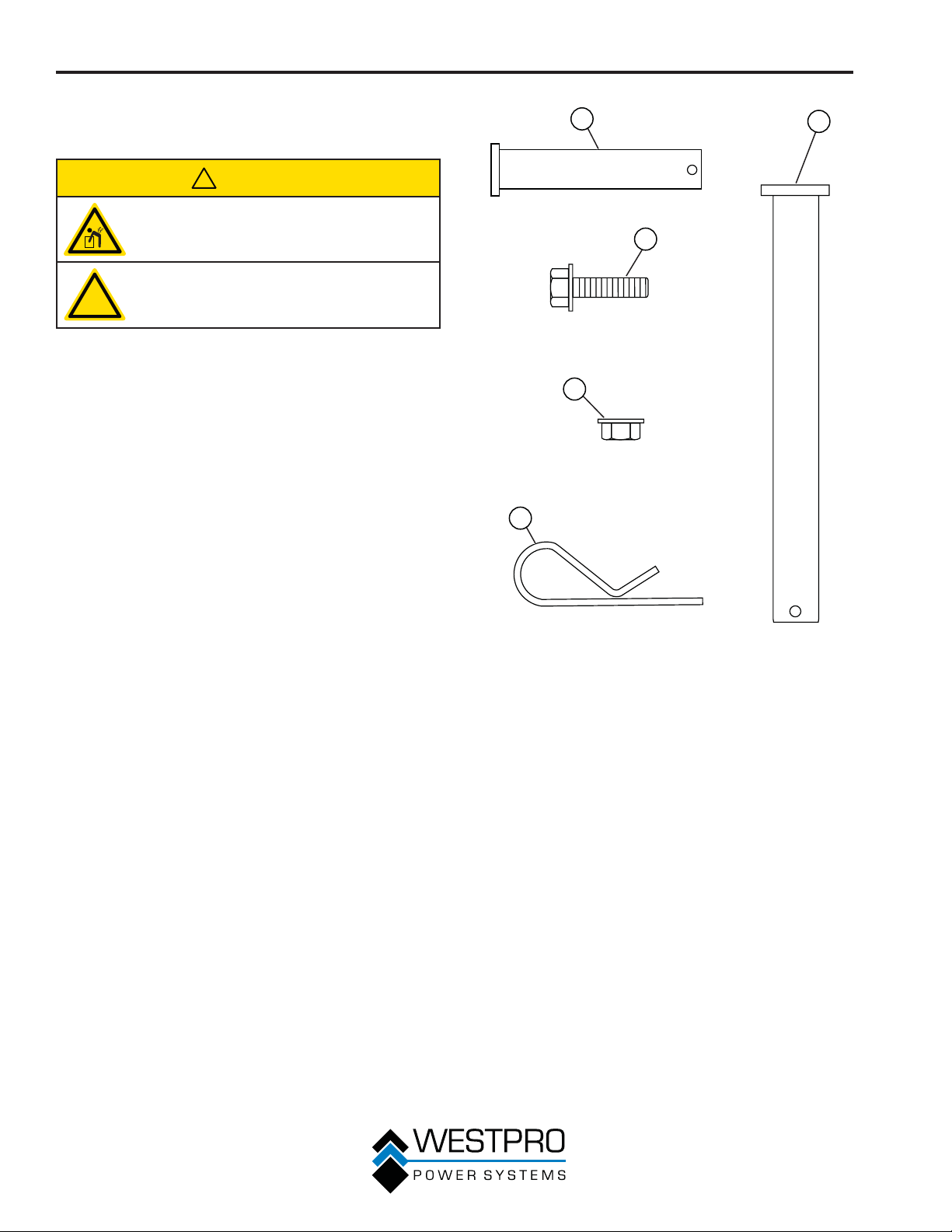
Figure 3 – Wheel Kit Hardware
1 - Clevis Pin
50 x 10 mm
(2 used)
2 - Flange Bolt
M6 x 18 mm
(2 used)
3 - Wheel Axle Pin
16 mm x 105 mm
(2 used)
4 - Locking Flange
Nut M6 (4 used)
5 - Hairpin Cotter
(4 used)
12
ASSEMBLY
ASSEMBLY
Before assembling the generator,
review Safety on page 6 and the
following safety messages.
!
CAUTION
Never lift the generator without
assistance. The generator is heavy and
lifting without assistance could result
in personal injury.
Never use the handles as a lifting
!
Assembling the generator will require lifting the unit
on one side. Make sure all engine oil and fuel are
drained from the unit prior to assembling.
Once assembled, the wheel kit is not intended for
on-road use. The wheel kit is designed for use on this
generator only.
point to support the entire weight of
the generator. Only use the handles
to move the generator by lifting the
handles and using the wheels to move
the generator.
Use caution when collapsing the
handles. Hands and fingers could get
caught and pinched.
NOTICE
1. Place generator on a flat surface.
2.
Place a piece of cardboard or other soft material
to tip the generator onto, to protect the frame
paint and prevent the generator from sliding. Tip
the generator onto its side as shown in Figure 4
(engine should be on the bottom).
Figure 4 – Tip the Generator onto its Side
Tools required – tool bag (included).
13
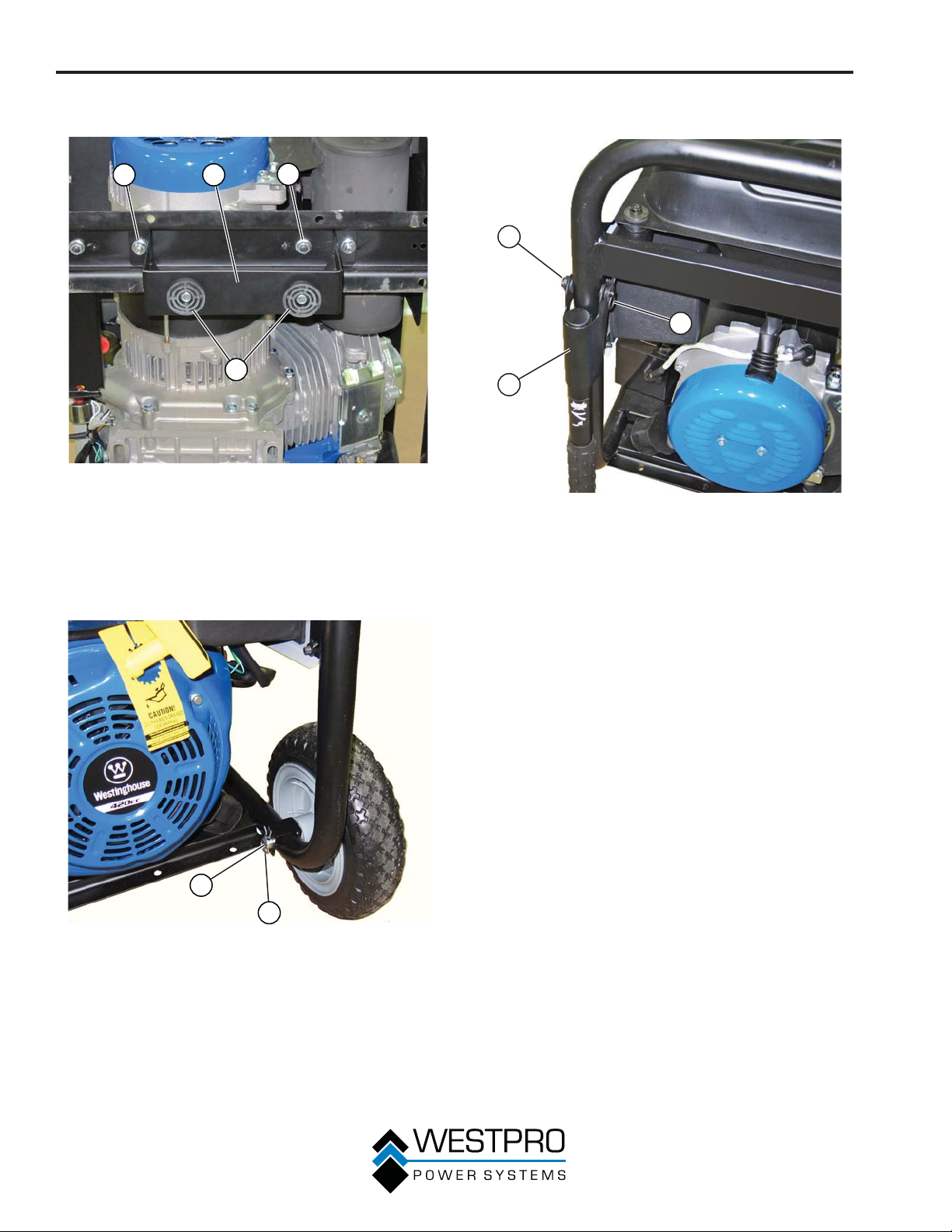
ASSEMBLY
3. Install the mounting foot to the frame using M6
flange bolts and nuts.
3 2
1
Figure 5 – Assemble Mounting Foot to Frame
1 - Rubber Pads
2 - Mounting Foot
4. Install the 16 mm x 105 mm axle pin through the
axle br
5. Install the hairpin cotter through the axle pin.
acket on the frame.
3
3 - M6 Flange Bolt
and Nut
6. Install the handles using the clevis pin and hairpin
cotter as sho
1
2
1 - Clevis Pin
2 - Handle
wn in Figure 7.
3
Figure 7 – Attaching the Handles
3 - Hairpin Cotter
1
2
Figure 6 – Assemble Wheels to Frame
1 - Axle Pin 2 - Hairpin Cotter
14
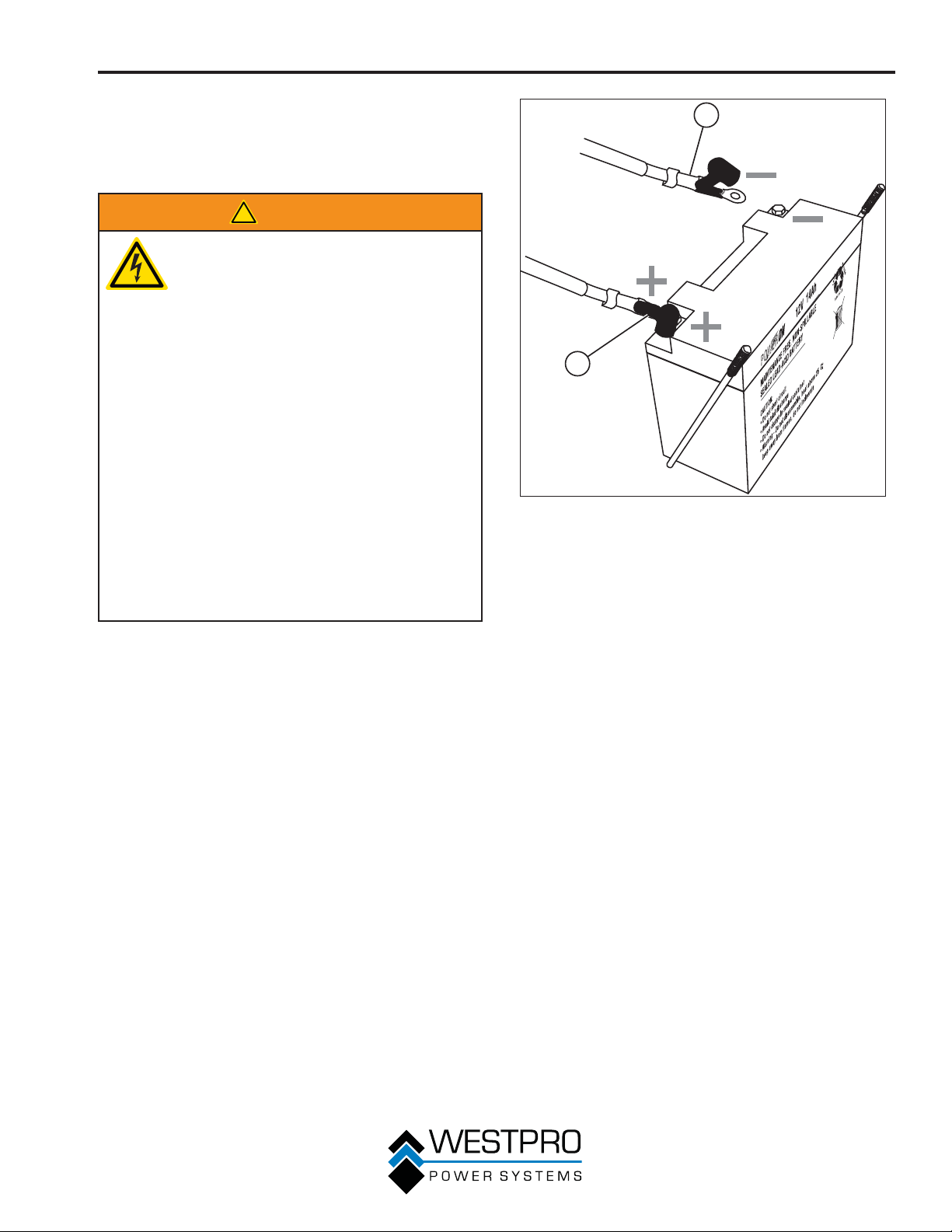
ASSEMBLY
INSTALLING THE BATTERY
(ELECTRIC START
GENERATORS ONLY)
!
WARNING
To avoid electric shock:
• ALWAYS connect the positive (+)
battery wire (red boot) first when
connecting battery wires.
• ALWAYS disconnect the negative (-)
battery wire (black boot) first when
disconnecting battery wires.
• NEVER connect the negative (-)
battery wire (black boot) to the
positive (+) post on the battery.
• NEVER connect the positive (+)
battery wire (red boot) to the negative
(-) post on the battery.
• NEVER touch both battery posts
simultaneously.
• NEVER place a metal tool across
both battery posts.
• ALWAYS use insulated or nonconducting tools when installing the
battery.
2
1
Figure 8 – Attaching the Negative (-) Battery Wire
(Black)
1 - Positive (+)
Battery Cable
(Red)
2 - Negative (-)
Battery Cable
(Black)
OTE:N The generator comes equipped with the
positive battery wire (red boot) already
attached.
1. Verify the positive (+) battery wire (red boot) is
securely tightened to the positiv
Make sure boot is over battery post.
2. Carefully remove the protective wrapping around
the lug of the negative (-) battery wire (black boot).
3. Locate negative (-) cable attached to alternator
cable, remove tie and route to the negative (-)
battery post.
4. Pull back the black boot and securely attach the
negative (-) battery wire (black boot) to the negative
(-) battery post as shown in Figure 8. Replace the
black boot so it protects the wire lug and battery
post.
e (+) battery post.
15
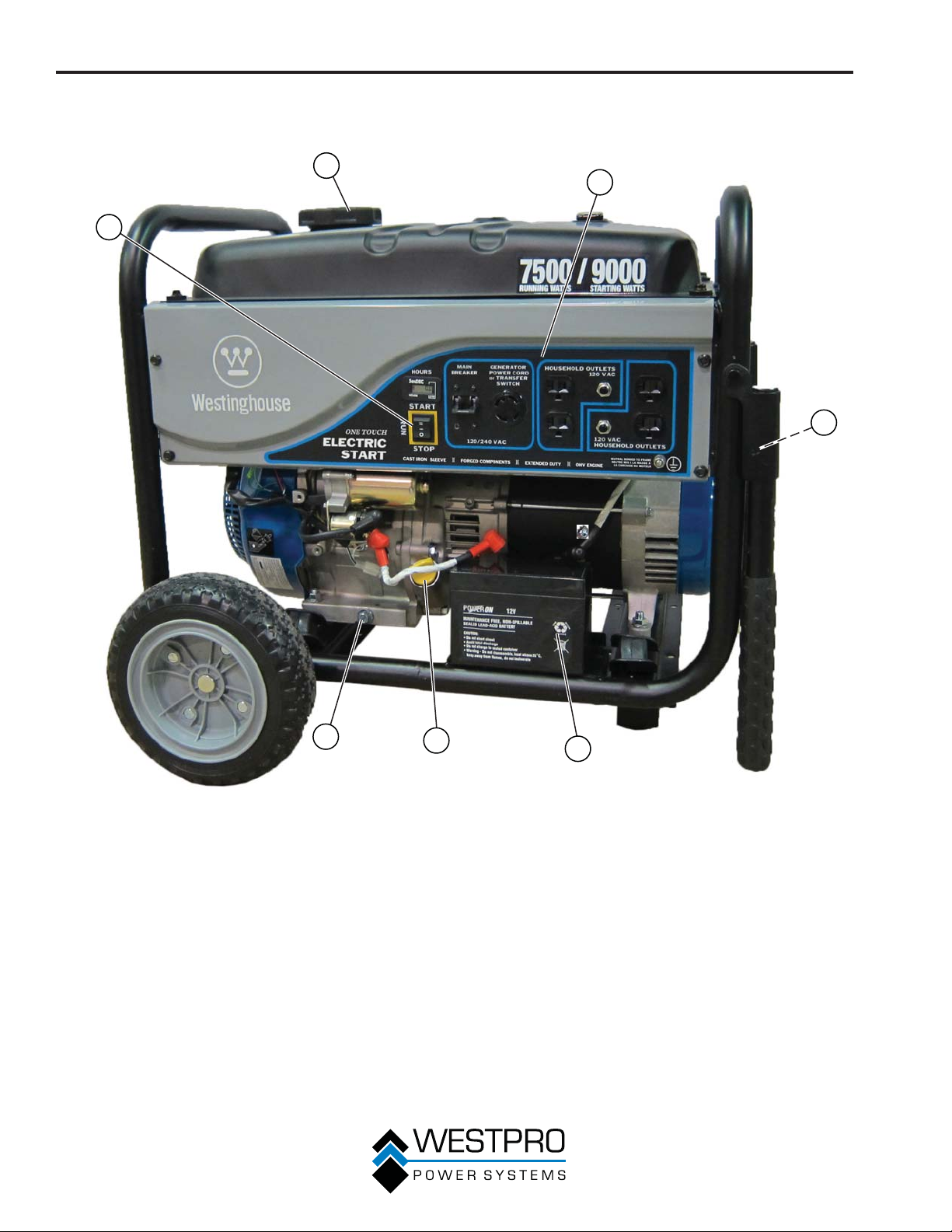
FEATURES
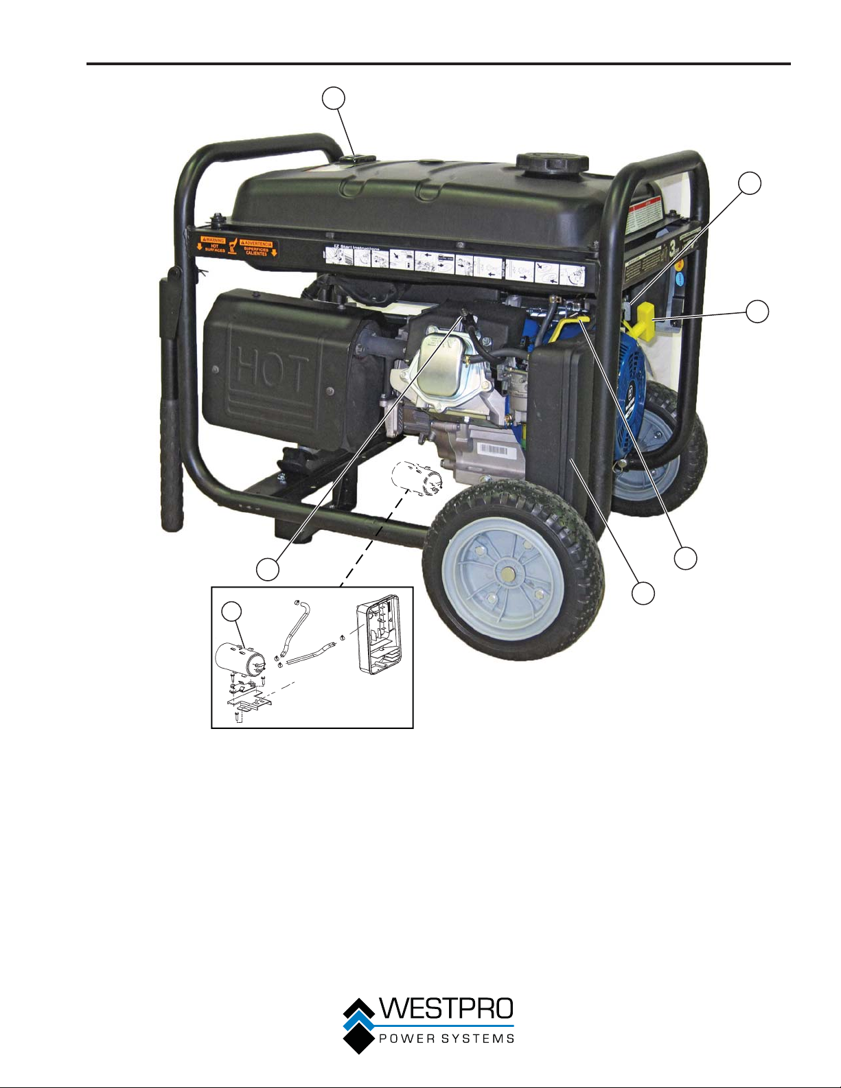
GENERAL GENERATOR FEATURES
2
1
3
4
7
1 - Engine Control Switch: Turns the engine on
and off.
2 - Fuel Cap: Close until clicking sound is heard.
3 - Control Panel: Contains the circuit breakers
and outlets.
4 - Muffler and Spark Arrester: Avoid contact
until engine is cooled down. Spark arrestor
prevents sparks from exiting the muffler. It
must be removed for servicing.
16
6
Figure 9
5
5 - Battery: For electric start models only.
6 - Oil Fill Plug/Dipstick: Must be removed to
add and check oil.
7 - Oil Drain Plug: Must be removed to drain
engine oil.
FEATURES
1
2
3
7
6
1 - Fuel Gauge: Indicates fuel level.
2 - Fuel Shutoff Valve: Controls the flow of fuel
to the engine.
3 - Recoil Handle: Must pull to start engine for
manual start units.
4 - Air Filter Cover: Must remove to service the
air filter.
5
4
Figure 10
5 - Choke Lever: Must be put in the ON position
to start the engine and returned to the OFF
position once the engine is running.
6 - CARB Canister: Model numbers follwed by
a “C” will be equipped with a carbon canister.
7 - Spark Plug Boot (Wire): Must be removed
when servicing the engine or the spark plug.
17
FEATURES
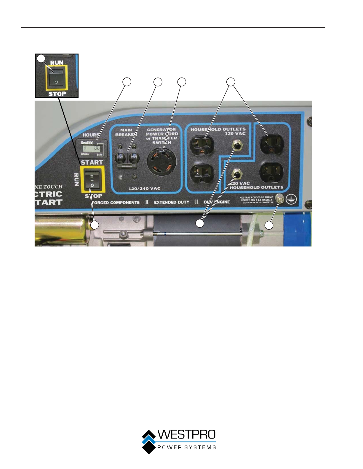
CONTROL PANEL FEATURES
1
2
8
3
4
6
5
7
Figure 11 – Control Panel Features
1. Engine Contr
Manual Start Units):
x RUN - In the RUN position, the switch
allows the generator to be started (for
manual start models).
x STOP - In the STOP position, the switch
stops the engine.
2. Hour Meter: Displays how many hours the
generator has been run (WHC7500E model).
3. Main Circuit Breaker: The main circuit
breaker controls total output of all outlets to
protect the generator.
4. 120/240-Volt, 30-Amp Twist Lock Outlet
(NEMA 14-30R): Outlet can supply either
120V or 240V output.
5. 120-Volt, 20-Amp Duplex Outlets (NEMA
5-20R): Each outlet is capable of carrying
a maximum of 20 amps on a single duplex
outlet or a combination of both receptacles.
ol Switch (RUN/STOP for
6. 20-Amp Circuit Breakers: Each circuit
breaker limits the current that can be
delivered through the 120-volt duplex outlets
to 20 amps.
7. Ground Terminal: The ground terminal is
used to ground the generator.
8. Engine Control Switch (START/RUN/STOP
for Electric Start Units):
x START - When the switch is momentarily
depressed and held in the START position,
the electric start motor engages and starts
the engine. Once the engine starts, release
the switch. (The switch will automatically go
to the RUN position.)
x RUN - Once started, the switch will remain
in the RUN position.
x STOP - To stop the engine, move the switch
to the STOP position.
18
OPERATION
BEFORE STARTING THE
GENERATOR
Before starting the generator, review
Safety on page 6.
Location Selection – Before starting the generator,
avoid exhaust and location hazards by verifying:
x You have selected a location to operate the
generator that is outdoors and well ventilated.
x You have selected a location with a level and solid
surface on which to place the generator.
x You have selected a location that is at least 6 feet
(1.8 m) away from any building, other equipment or
combustible material.
x If the generator is located close to a building, make
sure it is not located near any windows, doors
and/or vents.
No Connected Loads – Make sure the generator
has no connected loads before starting it. To ensure
there are no connected loads, unplug any electrical
extension cords that are plugged into the control panel
receptacles.
NOTICE
Starting the generator with loads already applied
to it could result in damage to any appliance being
powered off the generator during the brief start-up
period.
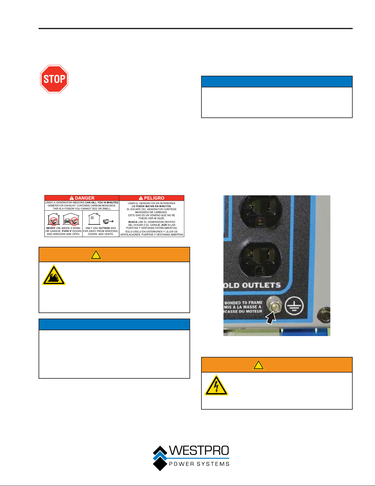
Grounding the Generator – The National Electric
Code (NEC), as well as many local electrical codes,
require the generator to be connected to earth ground
before operating. There is a permanent conductor
between the generator (stator windings) and the frame.
Before starting the generator, make sure it is connected
to earth ground by connecting the ground terminal on
the control panel (see Figure 12) to earth ground using
copper wire (minimum 10 AWG). Consult a qualified
electrician for local grounding requirements.
!
WARNING
Always operate the generator on a level
surface. Placing the generator on nonlevel surfaces can cause the generator
to tip over, causing fuel and oil to spill.
Spilled fuel can ignite if it comes in
contact with an ignition source such as
a very hot surface.
NOTICE
Only operate the generator on a solid, level surface.
Operating the generator on a surface with loose
material such as sand or grass clippings can cause
debris to be ingested by the generator that could:
• Block cooling vents
• Block air intake system
Weather – Never operate your generator outdoors
during rain, snow or any combination of weather
conditions that could lead to moisture collecting on, in
or around the generator.
Dry Surface – Always operate the generator on a dry
surface free of any moisture.
Figure 12 – Ground Terminal on the Control Panel
!
WARNING
Be sure the generator is properly
connected to earth ground before
operating. The generator must be
grounded to prevent electrical shock
due to faulty appliances.
19
OPERATION
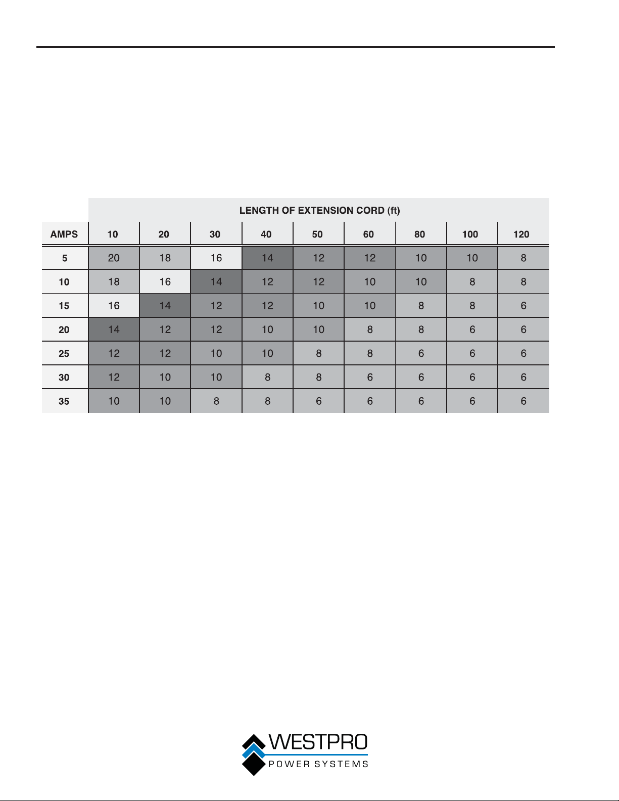
Using Extension Cords – Westpro Power Systems
assumes no responsibility for the content within this
table. The use of this table is the responsibility of the
user only. This table is intended for reference only. The
results produced by using this table are not guaranteed
to be correct or applicable in all situations as the type
and construction of cords are highly variable. Always
check with local regulations and a licensed electrician
prior to installing or connecting an electrical appliance.
Extension Cord Wire Gauge Size
20
OPERATION
ADDING / CHECKING ENGINE
FLUIDS AND FUEL
Before adding/checking engine
fluids and fuel, review Safety on
page 6.
!
DANGER
Filling the fuel tank with gasoline while
the generator is running can cause
gasoline to leak and come in contact
with hot surfaces that can ignite the
gasoline.
Before starting the generator, always check the level of:
x Engine oil
x Gasoline in the fuel tank
Once the generator is started and the engine gets
warm, it is not safe to add gasoline to the fuel tank or
engine oil to the engine while the engine is running or
the engine and muffler are hot.
Checking and / or Adding Engine Oil
!
WARNING
Internal pressure can build in the
engine crankcase while the engine
is running. Removing the oil fill plug/
dipstick while the engine is hot can
cause extremely hot oil to spray out
of the crankcase and can severely
burn skin. Allow engine oil to cool for
several minutes before removing the oil
fill plug/dipstick.
The unit as shipped does not contain oil in the
engine. You must add engine oil before starting the
generator for the first time. See Checking Engine Oil
on page 27 and Adding Engine Oil on page 28
for instructions on checking engine oil level and the
procedure for adding engine oil.
NOTICE
The generator does not contain engine oil as shipped.
Attempting to start the engine without adding
engine oil can permanently damage internal engine
components.
Adding Gasoline to the Fuel Tank
!
WARNING
Never refuel the generator while the
engine is running.
Always turn the engine off and allow
the generator to cool before refueling.
Required Gasoline – Only use gasoline that meets the
following requirements:
x Unleaded gasoline only
x Gasoline with maximum 10% ethanol added
x Gasoline with an 87 octane rating or higher
Filling the Fuel Tank – Follow the steps below to fill the
fuel tank:
1. Shut off the generator.
Allow the generator to cool down so all surface
2.
areas of the muffler and engine are cool to the
touch.
3. Move the generator to a flat surface.
4. Clean area around the fuel cap.
5. Remove the fuel cap by rotating counterclockwise.
6. Slowly add gasoline into the fuel tank. Be very
careful not to overfill the tank. The gasoline level
should NOT be higher than the bottom of the filler
neck (see Figure 13).
7. Install the fuel cap by rotating clockwise until
you hear a click, indicating the cap is completely
installed.
Figure 13 – Maximum Gasoline Fill Level
21
OPERATION
!
CAUTION
Avoid prolonged skin contact with
!
gasoline. Avoid prolonged breathing of
gasoline vapors.
STARTING THE GENERATOR
Before starting the generator, review
Safety on page 6.
Before attempting to start the generator, verify the
following:
x The engine is filled with engine oil (see Checking
Engine Oil on page 27).
x The generator is situated in a proper location (see
Location Selection on page 19).
x The generator is on a dry surface (see Weather and
Dry Surface on page 19).
x All loads are disconnected from the generator (see
No Connected Loads on page 19).
x The generator is properly grounded (see Grounding
the Generator on page 19).
!
DANGER
Never use the generator in a location
that is wet or damp. Never expose the
generator to rain, snow, water spray or
standing water while in use. Protect the
generator from all hazardous weather
conditions. Moisture or ice can cause a
short circuit or other malfunction in the
electrical circuit.
Never operate the generator in an
enclosed area. Engine exhaust
contains carbon monoxide. Only
operate the generator outside and away
from windows, doors and vents.
NOTICE
The engine is equipped with a low oil shutdown
switch. If the oil level becomes low, the engine will
shut down and will not start until the oil is filled to the
proper level.
Be sure the engine has the proper oil level before
using. Failure to verify that the engine has the proper
oil level could result in engine damage.
Disconnect all loads from the generator before
starting. Failure to verify all loads are disconnected
prior to starting the generator could result in damage
to the connected appliances.
Manually Starting a Generator
OTE:N This procedure can also be used on an
electric start generator.
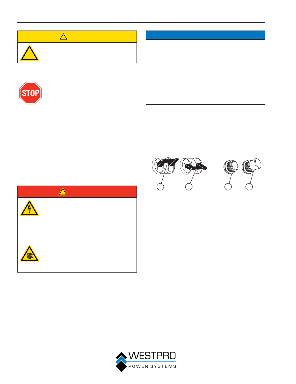
1. Make sure the circuit breakers are properly set (see
Figure 14).
1 2 3 4
Figure 14 – Breakers
1 - 240/120V Main
Circuit Breaker
Operating
Position
2 - 240/120V Main
Circuit Breaker
Tripped Position
3 - 120V Circuit
Breaker
Operating
Position
4 - 120V Circuit
Breaker Tripped
Position
22
OPERATION
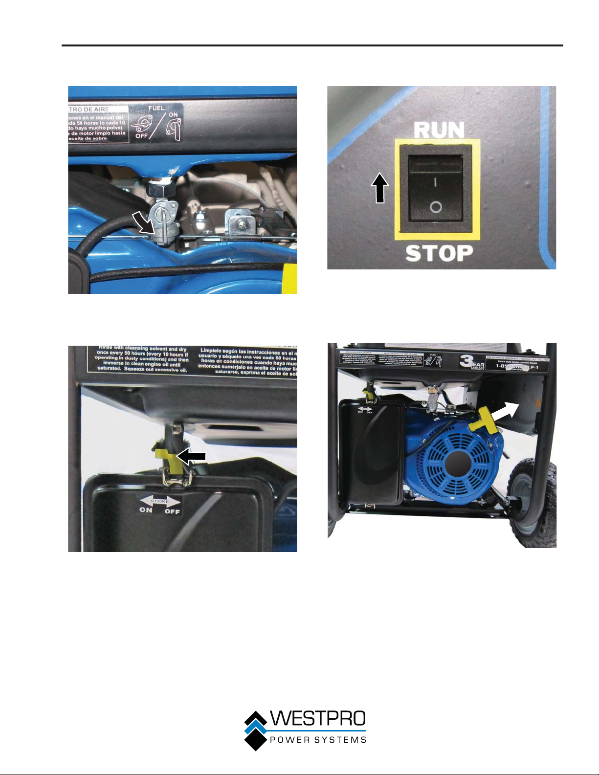
2. Move the fuel shutoff valve to the ON position (see
Figure 15).
Figure 15 – Fuel Shutoff Valve in the ON Position
3. Move the choke lever to the ON position (see
Figure 16).
4. Push the engine control switch into the RU
position (see Figure 17).
Figure 17 – Engine Control Switch
5. Firmly grasp and pull the recoil handle slowly until
you feel increased resistance. At this point, apply a
rapid pull while pulling up and slightly away from the
generator (see Figure 18).
N
Figure 16 – Choke Lever
6. As the engine starts and stabilizes, gradually move
the choke lever back to the OFF position.
23
Figure 18
 Loading...