

Westinghouse WH1000i, WH2000iXLT Owner's Manual

California
Proposition 65 Warning
The engine exhaust from this product
contains chemicals known to the state of
California to cause cancer, birth defects
or other reproductive harm.
Proposition 65 Warning
Certain components in this product and its
related accessories contain chemicals
known to the state of California to cause
cancer, birth defects or other reproductive
harm. Wash hands after handling.
California
DISCLAIMERS:
All information, illustrations and specifications in this manual are based on the latest information available at
the time of publishing. The illustrations used in this manual are intended as representative reference views only.
Moreover, because of our continuous product improvement policy, we may modify information, illustrations and/or
specifications to explain and/or exemplify a product, service or maintenance improvement. We reserve the right to
make any change at any time without notice. Some images may vary depending upon which model is shown.
ALL RIGHTS RESERVED:
No part of this publication may be reproduced or used in any form by any means – graphic, electronic or
mechanical, including photocopying, recording, taping or information storage and retrieval systems – without the
written permission of Westpro Power Systems, LLC.
2
CONGRATULATIONS ON OWNING A WESTINGHOUSE
INVERTER
!
DANGER
This manual contains important instructions for operating this inverter. For your safety and the
!
For Your Records:
Date of Purchase: Inverter Model Number:
Purchased from Store/Dealer: Inverter Serial Number:
Purchase Receipt: (retain your purchase receipt to ensure trouble-free warranty coverage)
Product Registration
To ensure trouble-free warranty coverage, it is important you register your Westinghouse inverter. You can register
your inverter by either:
1. Filling in the product registration form below and mailing to:
2. Registering your product online at www.westpropower.com
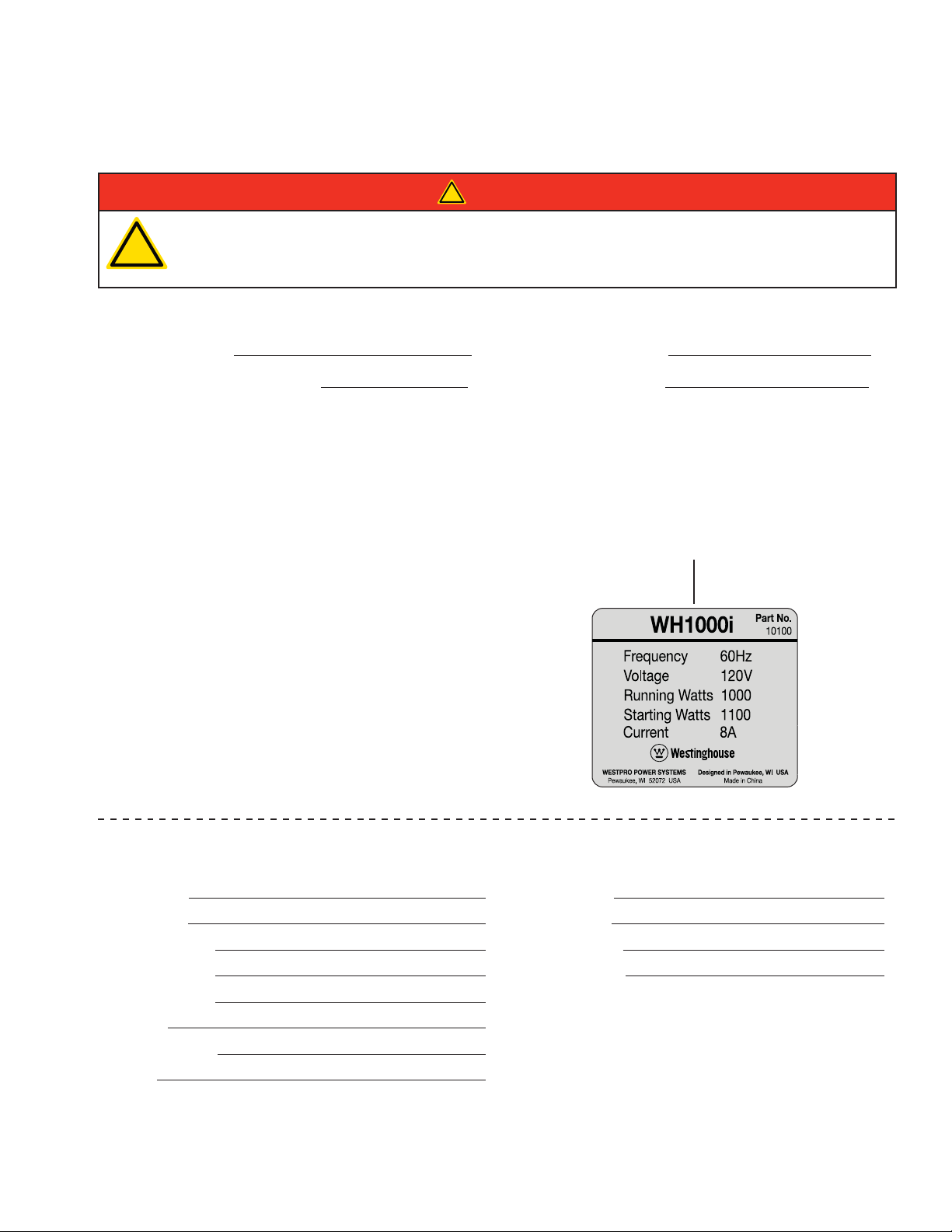
To register your inverter you will need to locate the model number
and serial number. The serial number tag is located toward the
bottom of the inverter housing on the opposite side of the muffler.
safety of others, be sure to read this manual thoroughly before operating the inverter. Failure to
properly follow all instructions and precautions can cause you and others to be seriously hurt
or killed.
Product Registration
Westpro Power Systems, LLC
W237 N2889 Woodgate Road, Unit B
Pewaukee, WI 53072
Model Number
Product Registration Form
PERSONAL INFORMATION INVERTER INFORMATION
First Name: Model Number:
Last Name: Serial Number:
Street Address: Date Purchased:
Street Address: Purchased From:
City, State, ZIP:
Country:
Phone Number:
E-Mail:


TABLE OF CONTENTS
CONGRATULATIONS ON OWNING A WESTINGHOUSE INVERTER ..............................................................3
For Your Records: .........................................................................................................................................3
Product Registration .....................................................................................................................................3
Product Registration Form ............................................................................................................................3
SAFETY ....................................................................................................................................................................7
SAFETY DEFINITIONS ......................................................................................................................................7
SAFETY SYMBOL DEFINITIONS ......................................................................................................................7
GENERAL SAFETY RULES ...............................................................................................................................8
SAFETY LABELS AND DECALS – WH1000i ................................................................................................... 10
SAFETY LABELS AND DECALS – WH2000i SERIES .....................................................................................12
SAFETY LABELS AND DECALS – WH2000iXLT .............................................................................................14
UNPACKING ...........................................................................................................................................................16
UNPACKING THE INVERTER ..........................................................................................................................16
Components: ..............................................................................................................................................16
FEATURES .............................................................................................................................................................17
GENERAL INVERTER FEATURES – WH1000i ...............................................................................................17
CONTROL PANEL FEATURES – WH1000i ......................................................................................................18
GENERAL INVERTER FEATURES – WH2000i SERIES .................................................................................19
CONTROL PANEL FEATURES – WH2000i SERIES ........................................................................................20
GENERAL INVERTER FEATURES – WH2000iXLT .........................................................................................21
CONTROL PANEL FEATURES – WH2000iXLT ................................................................................................22
OPERATION ...........................................................................................................................................................23
BEFORE STARTING THE INVERTER..............................................................................................................23
INVERTER PARALLELING OPERATION – WH2000iXLT ONLY ......................................................................24
INITIAL OIL FILL ...............................................................................................................................................25
WH1000i .....................................................................................................................................................25
WH2000i Series ..........................................................................................................................................26
ADDING / CHECKING ENGINE FLUIDS AND FUEL .......................................................................................28
Checking and / or Adding Engine Oil ..........................................................................................................28
Adding Gasoline to the Fuel Tank ...............................................................................................................28
STARTING THE INVERTER .............................................................................................................................29
Using Efficiency Mode ................................................................................................................................30
Resetting the Reset Breaker ......................................................................................................................30
STOPPING THE INVERTER.............................................................................................................................31
Normal Operation .......................................................................................................................................31
During an Emergency .................................................................................................................................31
MAINTENANCE ......................................................................................................................................................32
MAINTENANCE ................................................................................................................................................32
Maintenance Schedule ...............................................................................................................................32
ENGINE OIL MAINTENANCE ..........................................................................................................................33
Engine Oil Specification ..............................................................................................................................33
Checking Engine Oil – WH1000i ................................................................................................................33
Checking Engine Oil – WH2000i Series .....................................................................................................34
Adding Engine Oil – WH1000i ....................................................................................................................34
Adding Engine Oil – WH2000i Series .........................................................................................................35
Changing Engine Oil – WH1000i ................................................................................................................35
Changing Engine Oil – WH2000i Series .....................................................................................................36
AIR FILTER MAINTENANCE ............................................................................................................................36
Cleaning the Air Filter – WH1000i ..............................................................................................................36
Cleaning the Air Filter – WH2000i Series ...................................................................................................37
DRAINING THE FLOAT BOWL .........................................................................................................................38
WH1000i .....................................................................................................................................................38
WH2000i Ser
SPARK PLUG MAINTENANCE ........................................................................................................................39
CLEANING THE SPARK ARRESTOR ..............................................................................................................41
CLEANING THE INVERTER .............................................................................................................................41
ies ..........................................................................................................................................39
5

TABLE OF CONTENTS
STORAGE .........................................................................................................................................................41
SERVICE PARTS ..............................................................................................................................................44
WH1000i Service Parts ..............................................................................................................................44
WH2000i Series Service Parts ...................................................................................................................46
TROUBLESHOOTING ............................................................................................................................................48
TROUBLESHOOTING ......................................................................................................................................48
6
SAFETY
SAFETY DEFINITIONS
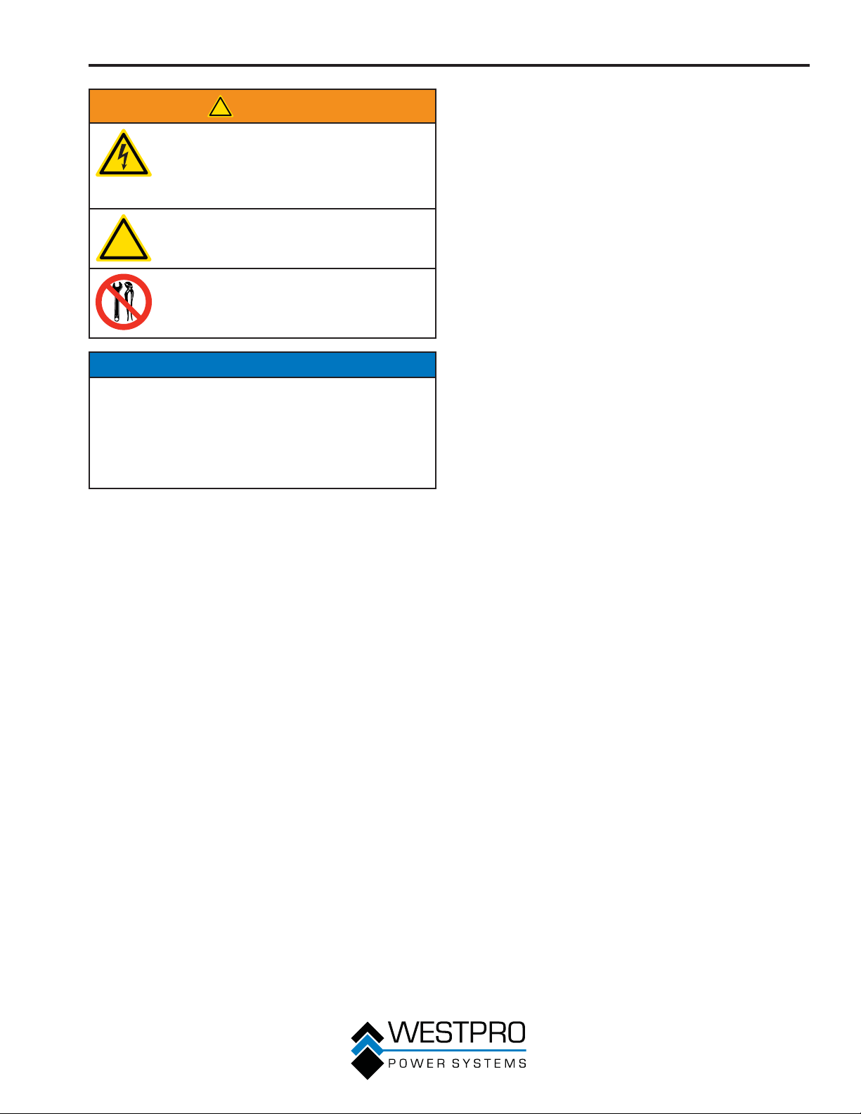
The words DANGER, WARNING, CAUTION and
NOTICE are used throughout this manual to highlight
important information. Be certain that the meanings of
these alerts are known to all who work on or near the
equipment.
This safety alert symbol appears
with most safety statements. It
!
Indicates a hazardous situation which, if not
avoided, will result in death or serious injury.
Indicates a hazardous situation which, if not
avoided, could result in death or serious injury.
Indicates a hazardous situation which, if not
avoided, could result in minor or moderate injury.
means attention, become alert, your
safety is involved! Please read and
abide by the message that follows
the safety alert symbol.
!
DANGER
!
WARNING
!
CAUTION
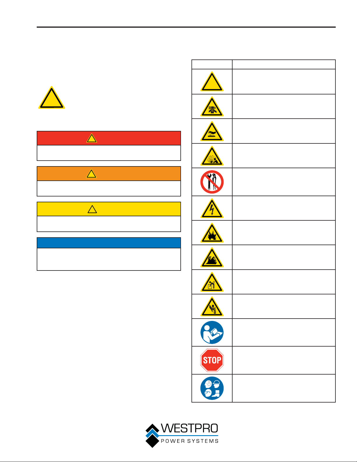
SAFETY SYMBOL
DEFINITIONS
Symbol Description
!
Safety Alert Symbol
Asphyxiation Hazard
Burn Hazard
Burst/Pressure Hazard
Don’t leave tools in the area
Electrical Shock Hazard
Explosion Hazard
NOTICE
Indicates a situation which can cause damage to the
inverter, personal property and/or the environment, or
cause the equipment to operate improperly.
OTE:N Indicates a procedure, practice or condition
that should be followed in order for the
inverter to function in the manner intended.
Fire Hazard
Lifting Hazard
Pinch-Point Hazard
Read Manufacturer’s Instructions
Read Safety Messages Before
Proceeding
Wear Personal Protective Equipment
(PPE)
7
SAFETY
GENERAL SAFETY RULES
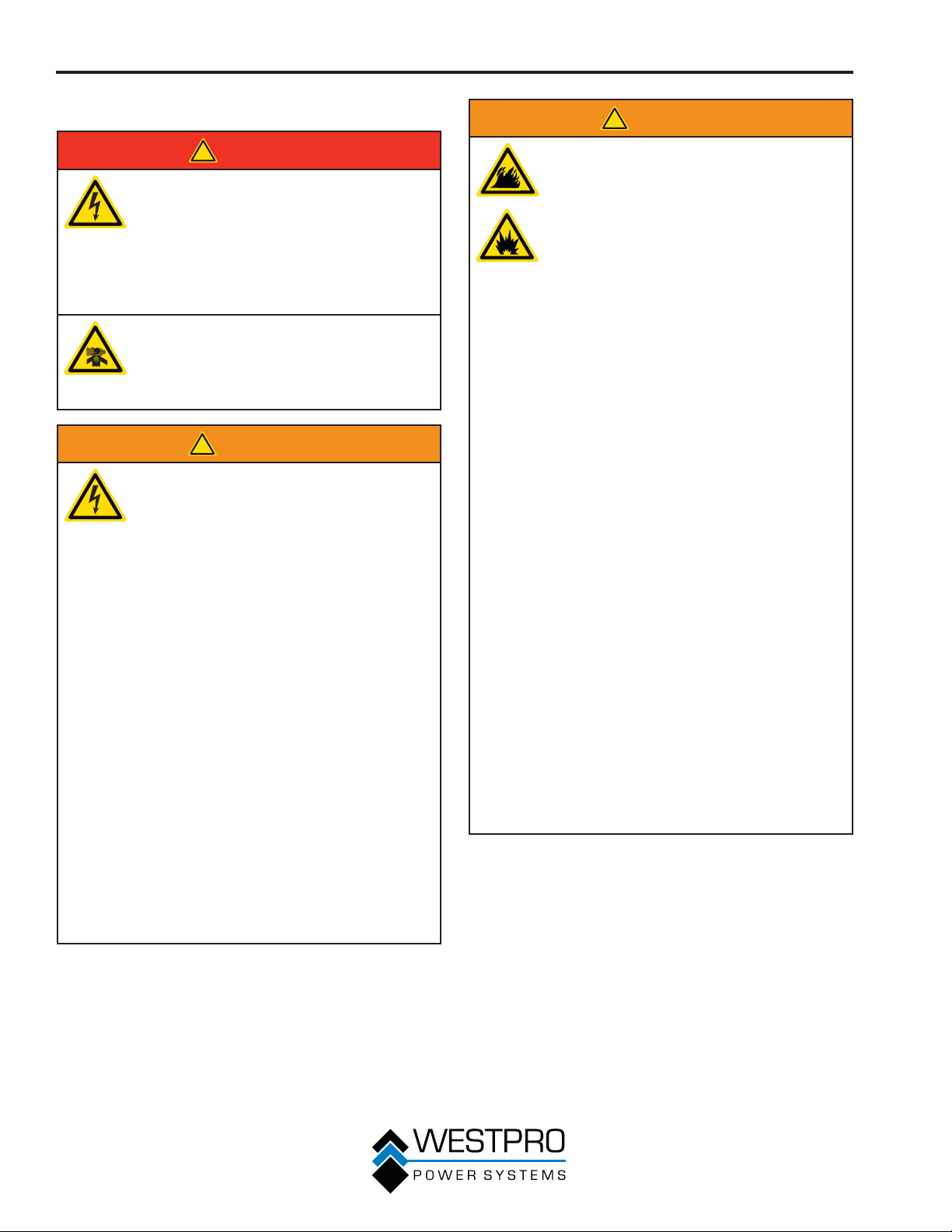
!
DANGER
Never use the inverter in a location
that is wet or damp. Never expose the
inverter to rain, snow, water spray or
standing water while in use. Protect
the inverter from all hazardous weather
conditions. Moisture or ice can cause a
short circuit or other malfunction in the
electrical circuit.
Never operate the inverter in an
enclosed area. Engine exhaust
contains carbon monoxide. Only
operate the inverter outside and away
from windows, doors and vents.
!
WARNING
Voltage produced by the inverter could
result in death or serious injury.
• Never operate the inverter in rain or a
floodplain unless proper precautions
are taken to avoid being subject to
rain or a flood.
• Never use worn or damaged
extension cords.
• Always have a licensed electrician
connect the inverter to the utility
circuit.
• Never touch an operating inverter if
the inverter is wet or if you have wet
hands.
• Never operate the inverter in highly
conductive areas such as around
metal decking or steel works.
• Always use grounded extension
cords. Always use three-wire or
double-insulated power tools.
• Never touch live terminals or bare
wires while the inverter is operating.
• Be sure the inverter is properly
grounded before operating.
!
WARNING
Gasoline and gasoline vapors are
extremely flammable and explosive
under certain conditions.
• Always refuel the inverter outdoors,
in a well-ventilated area.
• Never remove the fuel cap with the
engine running.
• Never refuel the inverter while the
engine is running. Always turn
engine off and allow the inverter to
cool before refueling.
• Only fill fuel tank with gasoline.
• Keep sparks, open flames or other
form of ignition (such as match,
cigarette, static electric source) away
when refueling.
• Never overfill the fuel tank. Leave
room for fuel to expand. Overfilling
the fuel tank can result in a sudden
overflow of gasoline and result in
spilled gasoline coming in contact
with HOT surfaces. Spilled fuel can
ignite. If fuel is spilled on the inverter,
wipe up any spills immediately.
Dispose of rag properly. Allow area
of spilled fuel to dry before operating
the inverter.
• Wear eye protection while refueling.
• Never use gasoline as a cleaning
agent.
• Store any containers containing
gasoline in a well-ventilated area,
away from any combustibles or
source of ignition.
• Check for fuel leaks after refueling.
Never operate the engine if a fuel leak
is discovered.
8
!
WARNING
Never operate the inverter if powered
items overheat, electrical output drops,
there is sparking, flames or smoke
coming from the inverter, or if the
receptacles are damaged.
Never use the inverter to power
medical support equipment.
!
Always remove any tools or other
service equipment used during
maintenance from the inverter before
operating.
NOTICE
Never modify the inverter.
Never operate the inverter if it vibrates at high levels,
if engine speed changes greatly or if the engine
misfires often.
Always disconnect tools or appliances from the
inverter before starting.
SAFETY
9
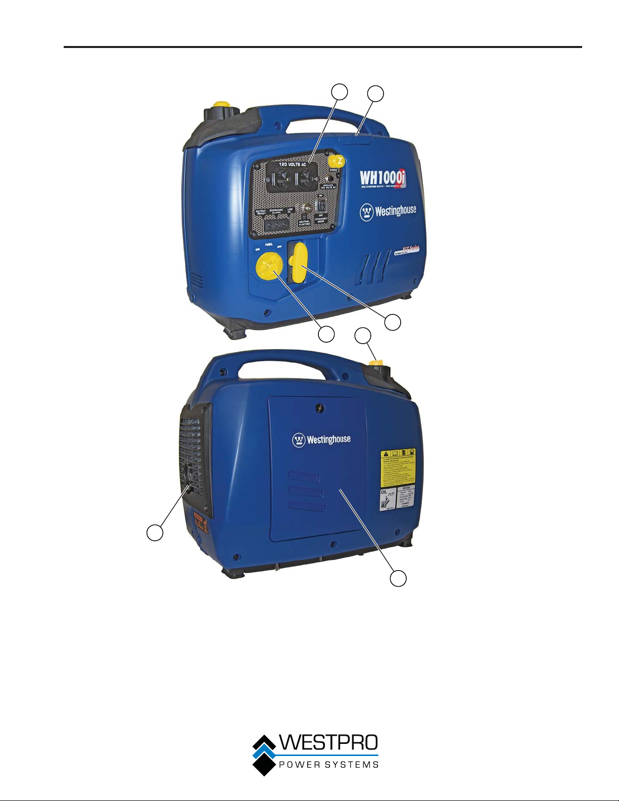
SAFETY
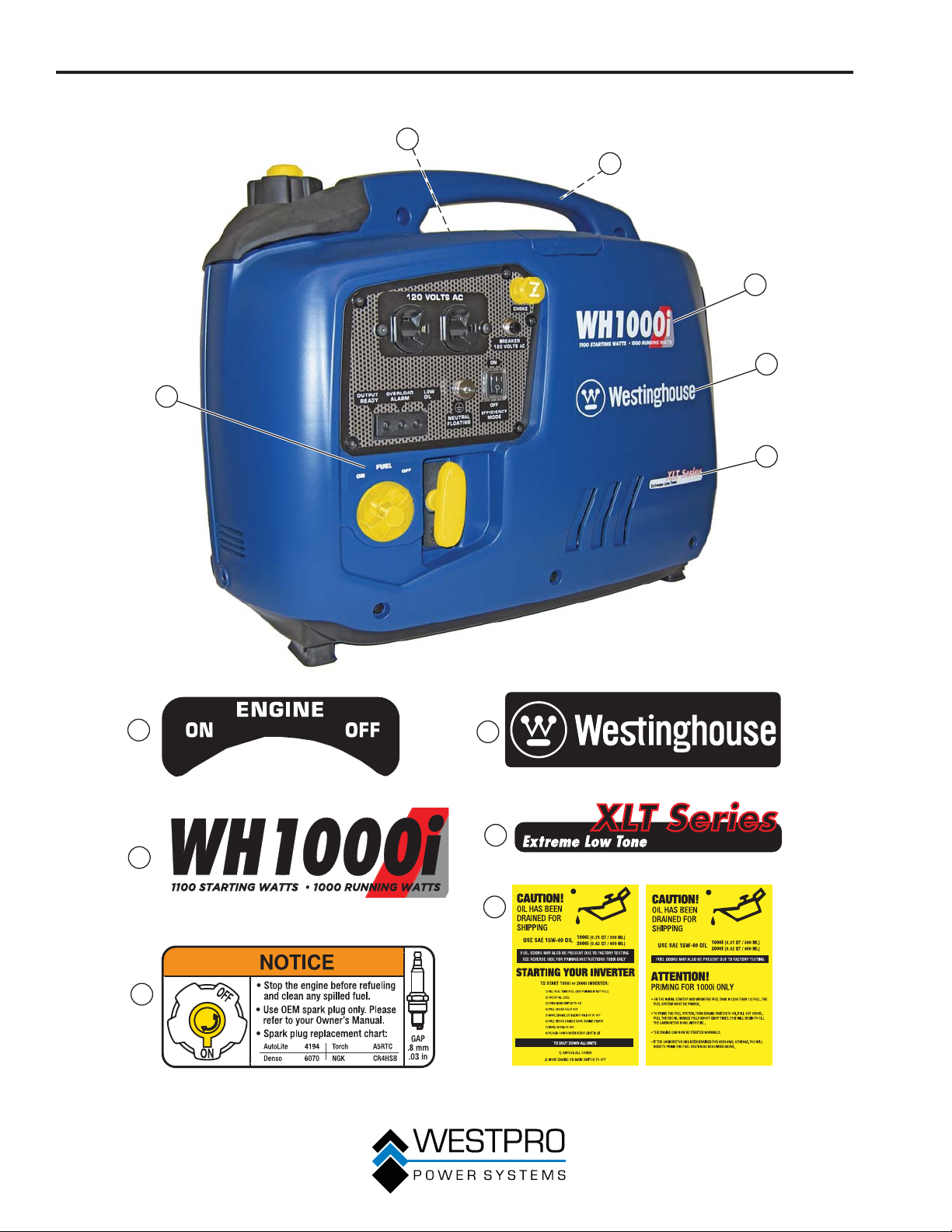
SAFETY LABELS AND DECALS – WH1000i
5
1
6
3
2
4
10
1
3
5
Figure 1
2
4
6
FRONT
BACK
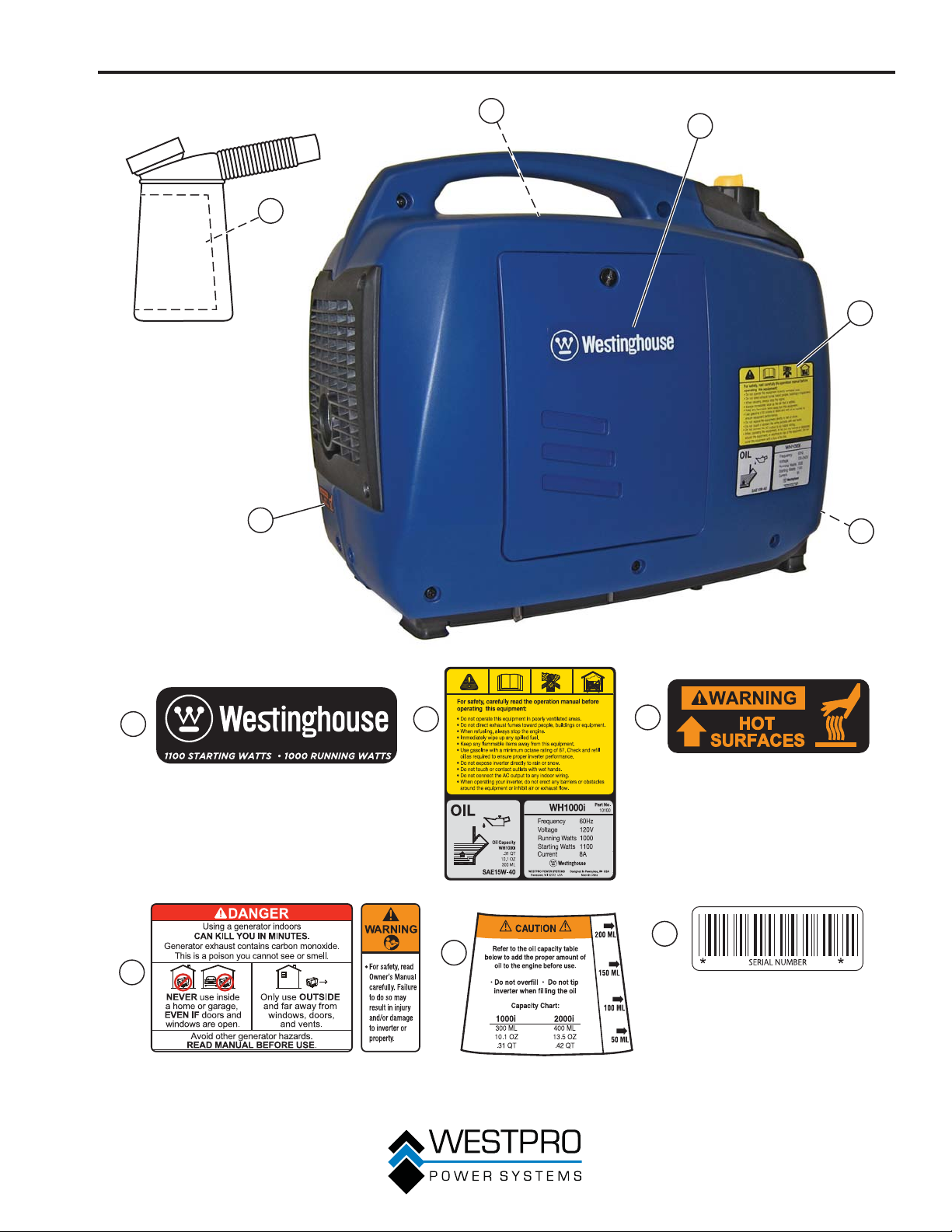
SAFETY
4
5
3
1
2
6
1
4
2
5
Figure 2
3
6
11
SAFETY
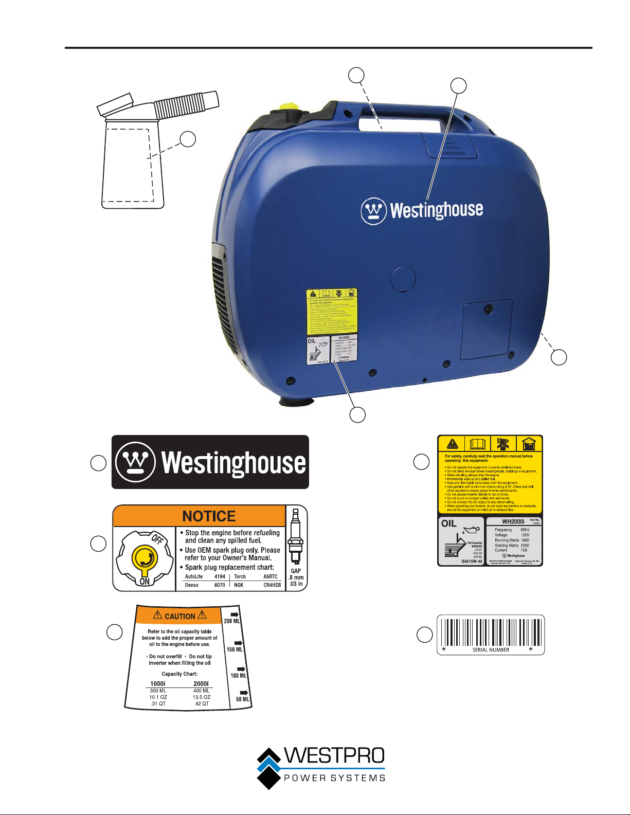
SAFETY LABELS AND DECALS – WH2000i SERIES
6
3
1
5
2
4
1
3
5
2
4
6
FRONT
BACK
12
Figure 3
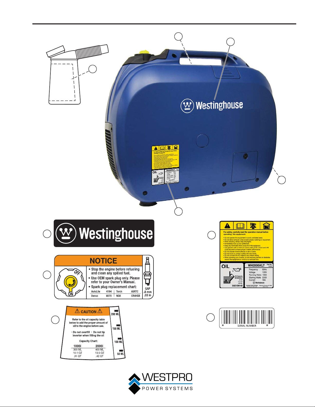
SAFETY
3
1
4
5
2
1
3
4
2
5
Figure 4
13
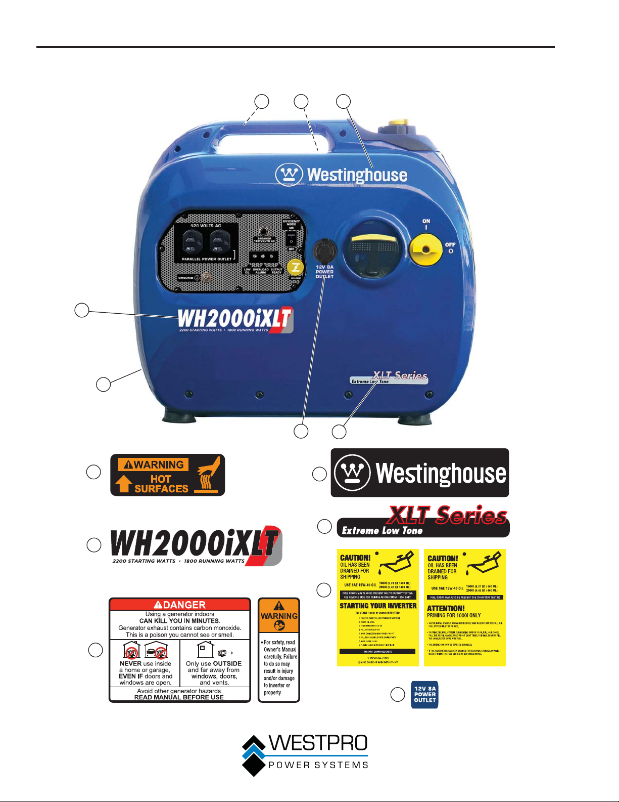
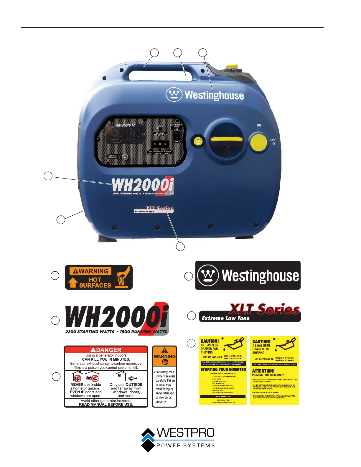
SAFETY
SAFETY LABELS AND DECALS – WH2000iXLT
6
3
1
5
2
7
1
3
5
Figure 5
4
2
4
6
FRONT
7
BACK
14
SAFETY
3
1
4
5
2
1
3
4
2
5
Figure 6
15

UNPACKING
UNPACKING THE INVERTER
!
CAUTION
Always have assistance when lifting
the inverter. The inverter is heavy;
lifting it could cause bodily harm.
Avoid cutting on or near staples to
prevent personal injury.
!
Tools required – box cutter or similar device.
1. Carefully cut the packing tape on top of the carton.
Fold back top flaps to reveal the manual. Remove
2.
the document and save it for reference.
3. Carefully cut two sides of the carton to remove the
inverter.
Components:
Tool Bag (1)
Screwdriver (1)
Bottle of SAE 15W-40 Oil (1)
(2000i only)
Oil Fill Bottle (1)
16
GENERAL INVERTER FEATURES – WH1000i
FEATURES
1
2
3
4
5
7
6
Figure 7
1 - Control Panel: Contains the reset breaker,
outlets and warning lights.
2 - Spark Plug Access Cover: Remove the
cover to service the spark plug.
3 - Recoil Handle: Pull to start the engine.
4 - Engine/Fuel Control Switch: Turns the
engine and the fuel on and off.
17
5 - Fuel Cap and Vent: Open the vent to run the
engine and close the vent when the engine is off.
6 - Engine Service Panel: Remove the panel to
access the engine for maintenance.
7 - Muffler and Spark Arrestor: Avoid contact
until the engine is cooled down. The spark
arrestor prevents sparks from exiting the
muffler. It must be removed for servicing.
FEATURES
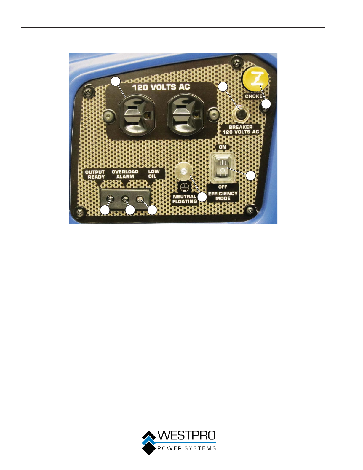
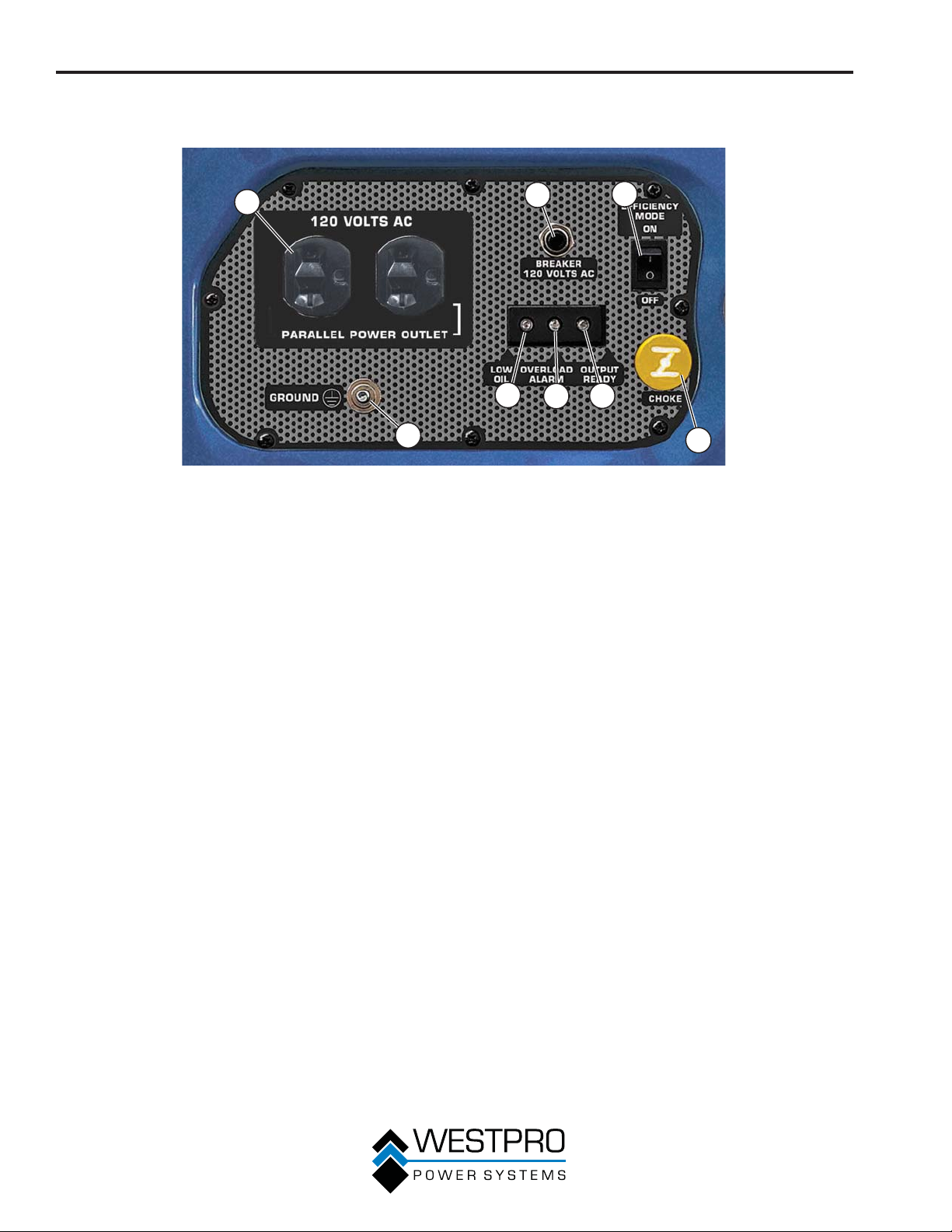
CONTROL PANEL FEATURES – WH1000i
1
678
Figure 8 – Control Panel Features
1 - 120-Volt, 20-Amp Duplex Outlet (NEMA
5-20R): The outlet is capable of carrying a
maximum of 20 amps.
2 - Reset Breaker: If the inverter is overloaded,
the reset breaker will trip. The engine will
continue to run, but there will be no output
from the inverter. Unplug the devices and
reduce the load. Push in the reset breaker to
reset it.
3 - Choke Knob: Pull out to the ON position
to start the engine, and push in to the OFF
position once the engine is running.
4 - Efficiency Mode Switch: When turned to the
ON position, the engine will sense the load
needed and run at a slower RPM to save fuel.
2
3
4
5
5 - Ground Terminal: The ground terminal is used
to externally ground the inverter.
6 - Low Oil LED: The red light will come on
and the engine will shut down if the oil level
becomes low. You must add oil to the correct
level before the inverter can be restarted.
7 - Overload LED: The red light will come on if the
inverter is overloaded. Decrease the load before
restoring inverter operations.
8 - Output Ready LED: The light will be green
when the inverter is ready to be used.
18
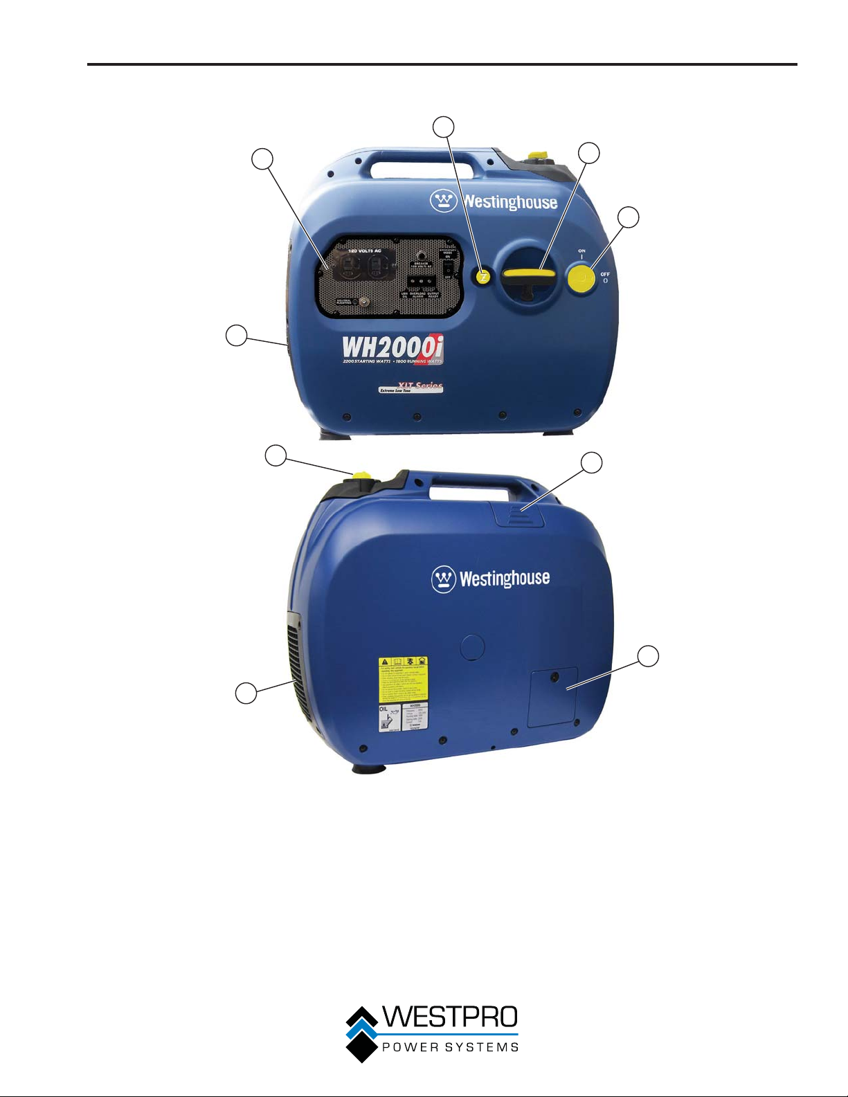
FEATURES
GENERAL INVERTER FEATURES – WH2000i SERIES
2
1
3
4
9
8
5
6
7
Figure 9
1 - Control Panel: Contains the reset breaker,
outlets and warning lights.
2 - Choke Knob: Pull out to the ON position
to start the engine, and push in to the OFF
position once the engine is running.
3 - Recoil Handle: Pull to start the engine.
4 - Engine/Fuel Control Switch: Turns the
engine and the fuel on and off.
5 - Spark Plug Access Cover: Remove the
cover to service the spark plug.
19
6 - Engine Oil Fill/Drain Plug Service Panel:
Remove the panel to access the engine oil fill/
drain plug for maintenance.
7 - Air Cleaner Access Panel: Remove the panel
to access the air cleaner for maintenance.
8 - Fuel Cap and Vent: Open vent to run the engine,
and close the vent when the engine is off.
9 - Muffler and Spark Arrestor: Avoid contact until
the engine is cooled down. The spark arrestor
prevents sparks from exiting the muffler. It must
be removed for servicing.
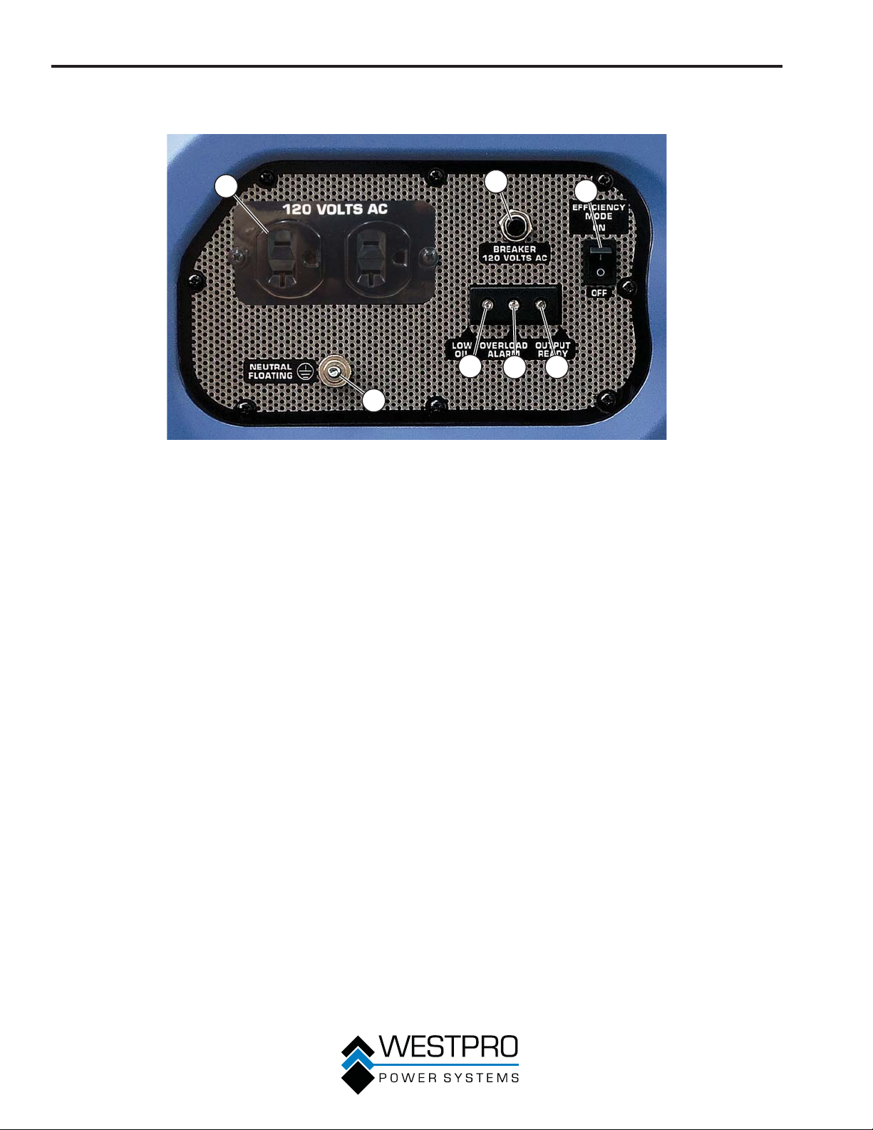
FEATURES
CONTROL PANEL FEATURES – WH2000i SERIES
1
7
Figure 10 – Control Panel Features
1 - 120-Volt, 20-Amp Duplex Outlet (NEMA
5-20R): The outlet is capable of carrying a
maximum of 20 amps.
2 - Reset Breaker: If the inverter is overloaded,
the reset breaker will trip. The engine will
continue to run, but there will be no output
from the inverter. Unplug the devices and
reduce the load. Push in the reset breaker to
reset it.
3 - Efficiency Mode Switch: When turned to the
ON position, the engine will sense the load
needed and run at a slower RPM to save fuel.
2
6
4 - Output Ready LED: The light will be green
5 - Overload LED: The red light will come on if
6 - Low Oil LED: The red light will come on
7 - Ground Terminal: The ground terminal is
5
when the inverter is ready to be used.
the inverter is overloaded. Decrease the load
before restoring inverter operations.
and the engine will shut down if the oil level
becomes low. You must add oil to the correct
level before the inverter can be restarted.
used to externally ground the inverter.
3
4
20
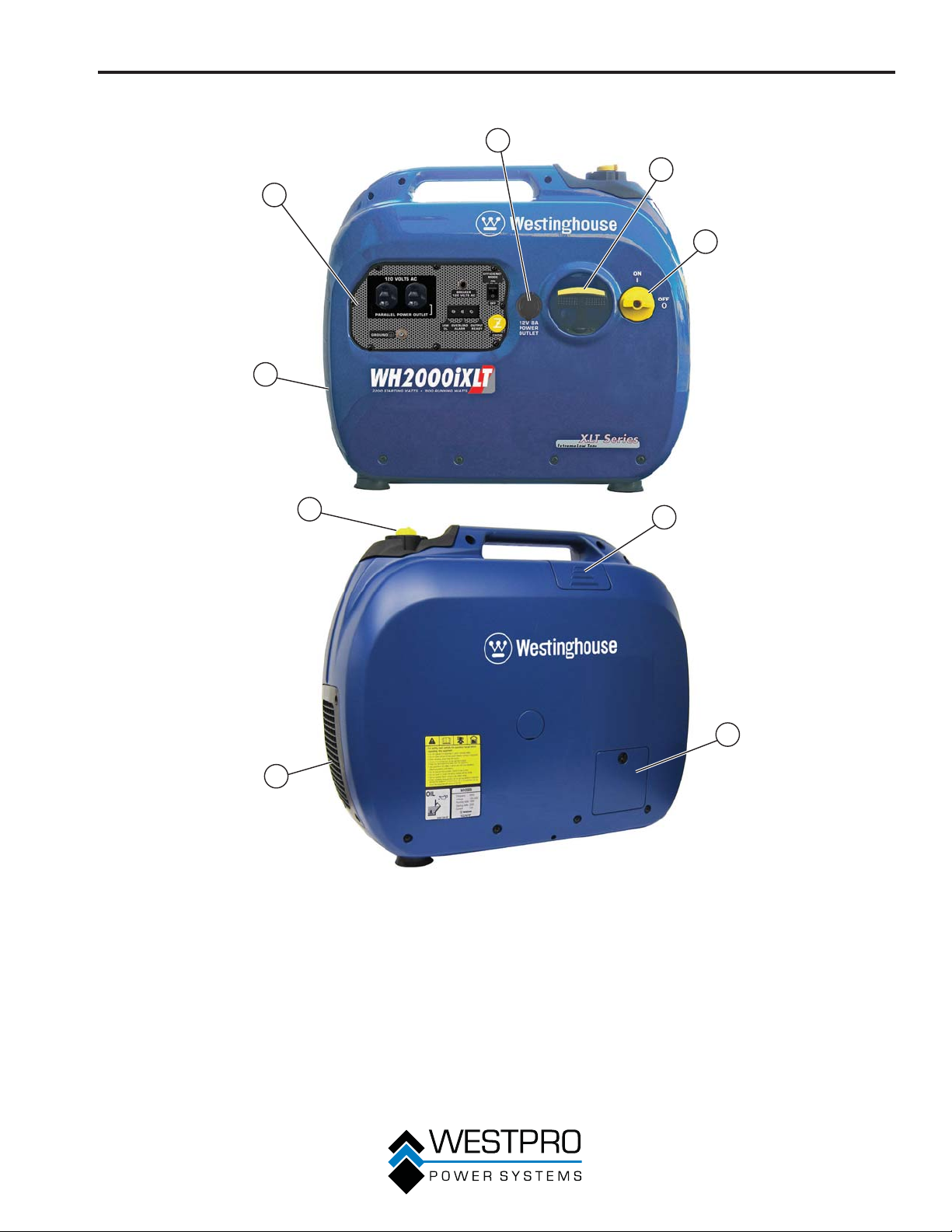
FEATURES
GENERAL INVERTER FEATURES – WH2000iXLT
2
3
1
9
4
8
7
1 - Control Panel: Contains the reset breaker,
outlets and warning lights.
2 - 12-Volt DC Power Socket: Provides 12-volt
DC power up to 8 amps.
3 - Recoil Handle: Pull to start the engine.
4 - Engine/Fuel Control Switch: Turns the
engine and the fuel on and off.
5 - Spark Plug Access Cover: Remove the
cover to service the spark plug.
5
6
Figure 11
6 - Engine Oil Fill/Drain Plug Service Panel:
Remove the panel to access the engine oil fill/
drain plug for maintenance.
7 - Air Cleaner Access Panel: Remove the panel
to access the air cleaner for maintenance.
8 - Fuel Cap and Vent: Open vent to run the engine,
and close the vent when the engine is off.
9 - Muffler and Spark Arrestor: Avoid contact until
the engine is cooled down. The spark arrestor
prevents sparks from exiting the muffler. It must
be removed for servicing.
21
FEATURES
CONTROL PANEL FEATURES – WH2000iXLT
1
8
Figure 12 – Control Panel Features
1 - 120-Volt, 20-Amp Duplex Outlet (NEMA
5-20R): The outlet is capable of carrying a
maximum of 20 amps.
2 - Reset Breaker: If the inverter is overloaded,
the reset breaker will trip. The engine will
continue to run, but there will be no output
from the inverter. Unplug the devices and
reduce the load. Push in the reset breaker to
reset it.
3 - Efficiency Mode Switch: When turned to the
ON position, the engine will sense the load
needed and run at a slower RPM to save fuel.
4 - Choke Knob: Pull out to the ON position
to start the engine, and push in to the OFF
position once the engine is running.
2
7
6
3
5
4
5 - Output Ready LED: The light will be green
when the inverter is ready to be used.
6 - Overload LED: The red light will come on if
the inverter is overloaded. Decrease the load
before restoring inverter operations.
7 - Low Oil LED: The red light will come on
and the engine will shut down if the oil level
becomes low. You must add oil to the correct
level before the inverter can be restarted.
8 - Ground Terminal: The ground terminal is
used to externally ground the inverter.
22
OPERATION
BEFORE STARTING THE
INVERTER
Before starting the inverter, review
Safety on page 7.
Location Selection – Before starting the inverter, avoid
exhaust and location hazards by verifying:
x You have selected a location to operate the inverter
that is outdoors and well ventilated.
x You have selected a location with a level and solid
surface on which to place the inverter.
x You have selected a location that is at least 6 feet
(1.8 m) away from any building, other equipment or
combustible material.
x If the inverter is located close to a building, make
sure it is not located near any windows, doors
and/or vents.
Weather – Never operate your inverter outdoors during
rain, snow or any combination of weather conditions
that could lead to moisture collecting on, in or around
the inverter.
Dry Surface – Always operate the inverter on a dry
surface free of any moisture.
No Connected Loads – Make sure the inverter
has no connected loads before starting it. To ensure
there are no connected loads, unplug any electrical
extension cords that are plugged into the control panel
receptacles.
NOTICE
Starting the inverter with loads already applied to
it could result in damage to any appliance being
powered off the inverter during the brief start-up
period.
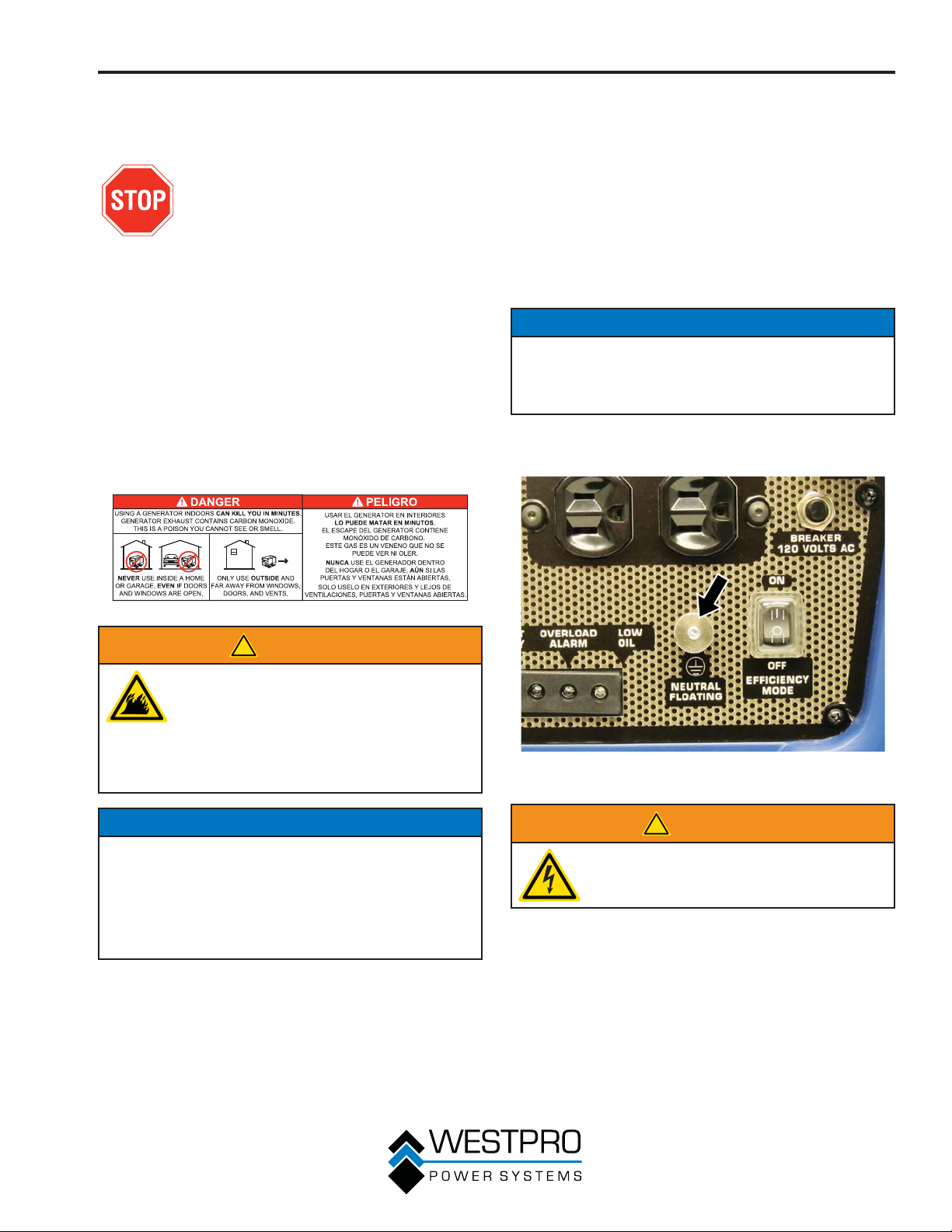
Grounding the Inverter – Consult with your local
municipalities for your grounding codes.
!
WARNING
Always operate the inverter on a level
surface. Placing the inverter on nonlevel surfaces can cause the inverter
to tip over, causing fuel and oil to spill.
Spilled fuel can ignite if it comes in
contact with an ignition source such as
a very hot surface.
NOTICE
Only operate the inverter on a solid, level surface.
Operating the inverter on a surface with loose
material such as sand or grass clippings can cause
debris to be ingested by the inverter that could:
• Block cooling vents
• Block air intake system
Figure 13 – Ground Terminal on the Control Panel
!
WARNING
Be sure the inverter is properly
connected to earth ground before
operating.
23
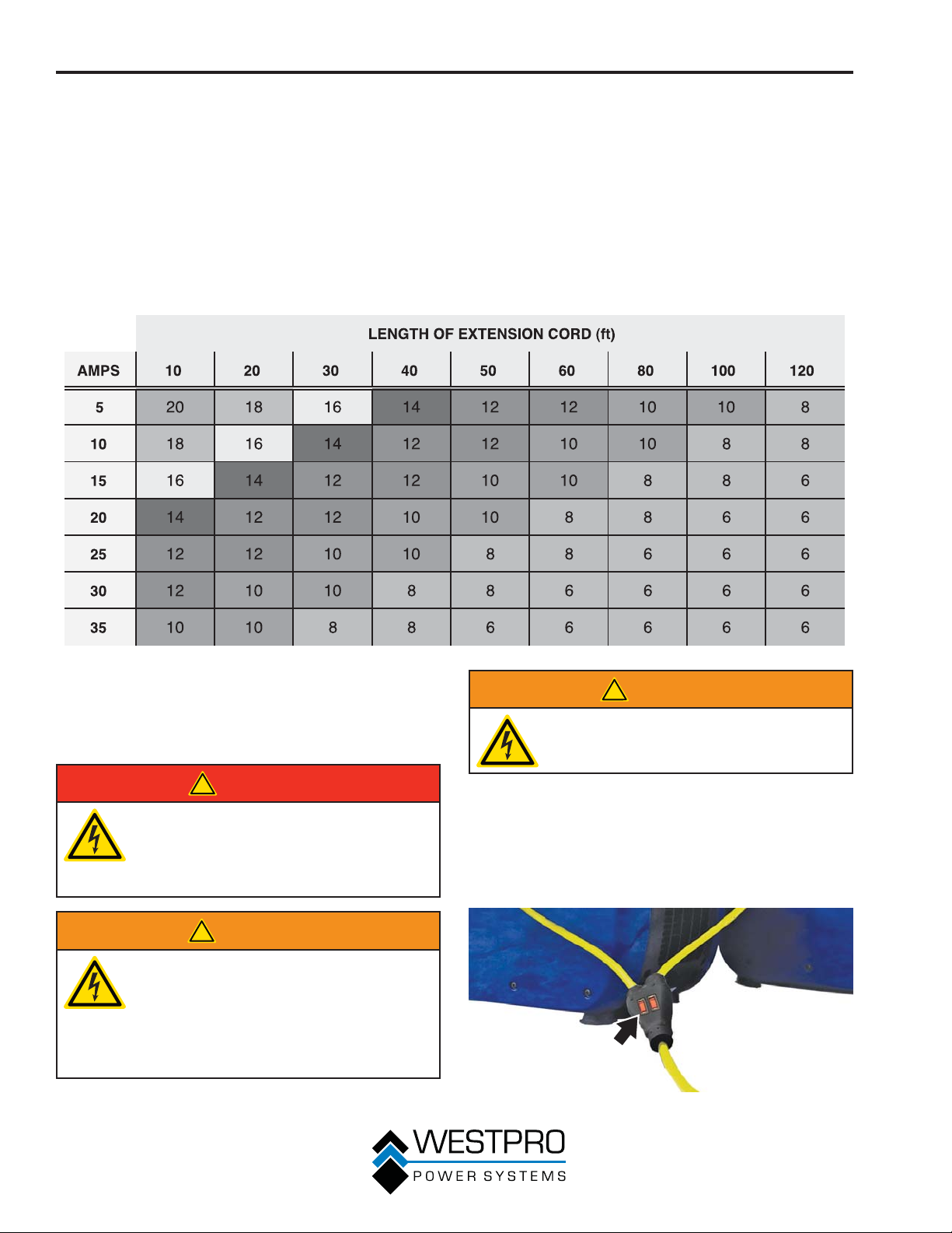
OPERATION
Using Extension Cords – Westpro Power Systems
assumes no responsibility for the content within this
table. The use of this table is the responsibility of the
user only. This table is intended for reference only. The
results produced by using this table are not guaranteed
to be correct or applicable in all situations as the type
and construction of cords are highly variable. Always
check with local regulations and a licensed electrician
prior to installing or connecting an electrical appliance.
Extension Cord Wire Gauge Size
INVERTER PARALLELING
OPERATION – WH2000iXLT
ONLY
!
DANGER
Never connect the paralleling cord to
the inverters with the inverters running.
The inverters must not be running and
both the paralleling cord switches must
be off when connecting the cords.
!
WARNING
Do not attempt to parallel the
Westinghouse inverter with any other
manufacturers’ inverters. Do not use
the paralleling cord for any application
other than inverter paralleling. Do not
use this cord on other manufacturers’
inverters.
!
WARNING
Always ensure that both ends of the
paralleling cord are switched off before
connecting the inverters.
1. Using only the Westinghouse paralleling cord (Part
No. 260041) with both cord switches set to OFF
(O), connect one male plug to one inverter and
connect the remaining plug into the other inverter.
Either of the receptacles on the inverters can be
used (see Figure 15).
Figure 14 – Paralleling Cord ON/OFF Switches
24
OPERATION
2. Start one of the inverters and wait until the ready
light is on.
3. Turn both cord switches to ON (I).
4. Start the remaining inverter; wait until the ready
light is on before connecting the load.
5. When power is present, a light will illuminate in the
three-prong plug that is plugged into the inverter.
Figure 15 – Paralleling Cord Connected
6. To stop the inverters, unplug all connected loads,
turn both cord switches to OFF (O) and unplug the
cord on each inverter.
7. If during operation the inverters’ output is stopped
due to overloading, reduce the connected load by
unplugging appliances, and then push the reset
button and restart the inverter. When the ready light
is on, the load can be reconnected.
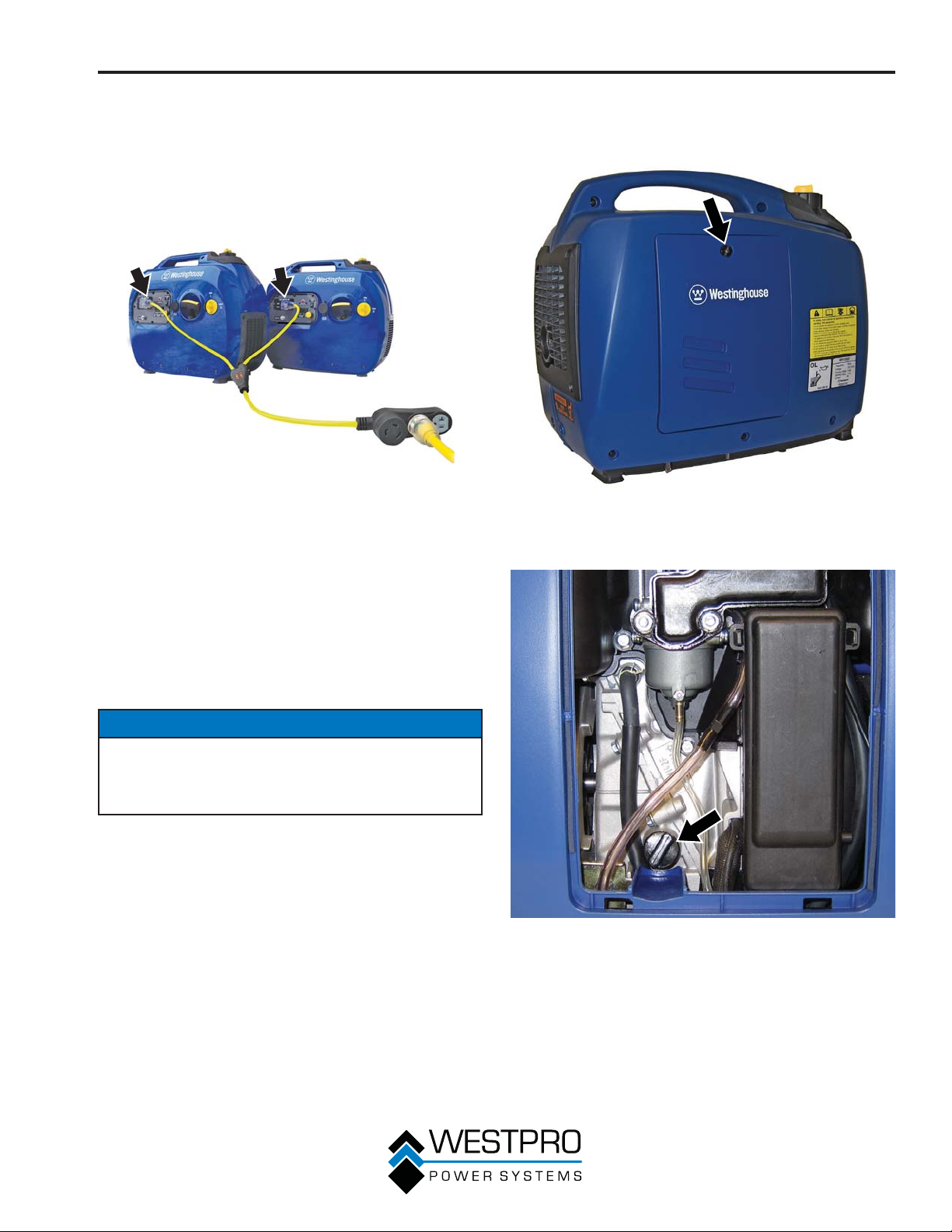
WH1000i
1. Loosen the screw and remove the engine service
panel to access the oil fill/drain plug (see Figure 16).
Figure 16 – WH1000i Engine Service Panel
2. Clean area around oil fill/drain plug and remove
plug (see Figure 17).
INITIAL OIL FILL
NOTICE
Engine oil must be added when the inverter is on
a flat, level surface, or an inaccurate reading may
result. Do not overfill. If the engine is overfilled with
oil, it can cause serious engine damage.
Figure 17 – Oil Fill/Drain Plug
OTE:N The oil capacity for the 1000i is 300 ml.
25
OPERATION
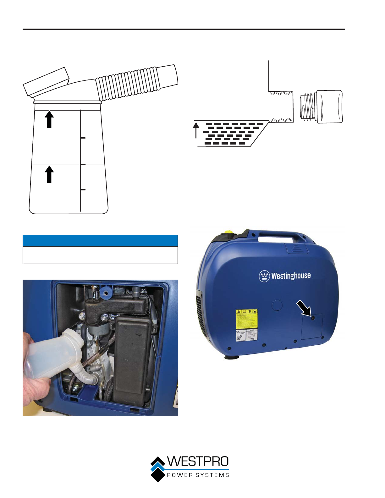
3. Using the supplied oil fill container and oil, fill the
container to the 2.0 mark on the container. Do not
overfill (see Figure 18).
2.0
1.5
1.0
0.5
Figure 18 – Oil Fill Container
6. Add the 100 ml of oil to the engine. The oil should
now be at the correct level (see Figure 20).
Figure 20 – Engine Oil Correct Level
7. Do not overfill. If oil level is too high, oil will drain out
through the fill plug.
WH2000i Series
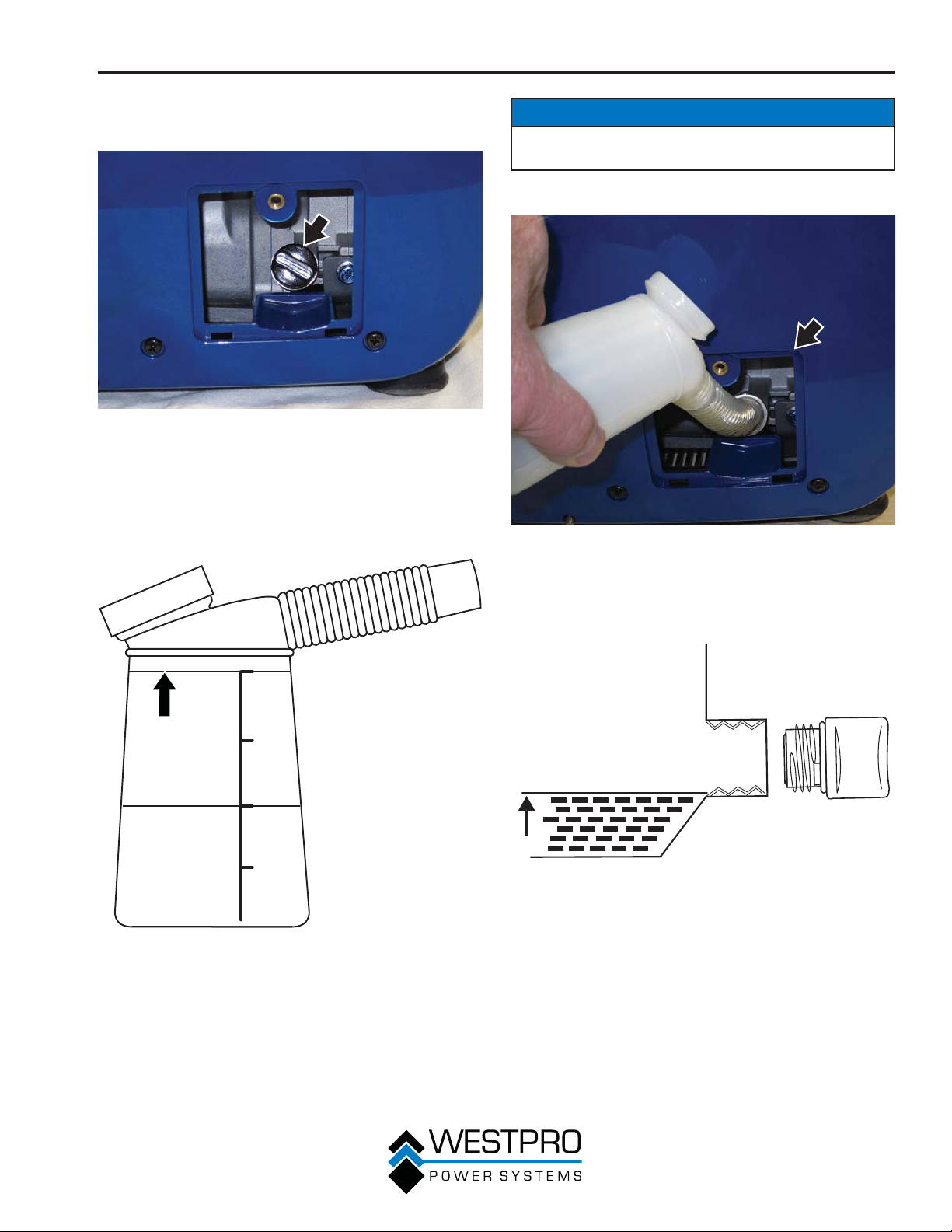
1. Loosen the screw and remove the engine oil fill/
drain plug service panel to access the oil fill/drain
plug (see Figure 21).
NOTICE
Do not tilt the inverter to add oil. It must be filled on a
flat, level surface.
4. Add the 200 ml of oil to the engine (see Figure 19).
Figure 19 – Adding Engine Oil
Figure 21 – WH2000i Engine Service Panel
5. Fill the container with oil again only to the 1.0 mark.
26
OPERATION
2. Clean the area around the oil fill/drain plug and
remove plug (see Figure 22).
Figure 22 – Oil Fill/Drain Plug
OTE:N The oil capacity for the 2000i series is
400 ml.
3. Using the supplied oil fill container and oil, fill the
container to the 2.0 mark on the container. Do not
overfill (see Figure 23).
NOTICE
Do not tilt the inverter to add oil. It must be filled on a
flat, level surface.
4. Add the 200 ml of oil to the engine (see Figure 24).
Figure 24 – Adding Engine Oil
2.0
1.5
1.0
0.5
Figure 23 – Oil Fill Container
5. Fill the container with oil again to the 2.0 mark.
6. Add the 200 ml of oil to the engine. The oil should
now be at the correct level (see Figure 25).
Figure 25 – Engine Oil Correct Level
7. Do not overfill. If oil level is too high, oil will drain out
through the fill plug.
27
OPERATION
ADDING / CHECKING ENGINE
FLUIDS AND FUEL
Before adding/checking engine
fluids and fuel, review Safety on
page 7.
!
DANGER
Filling the fuel tank with gasoline
while the inverter is running can cause
gasoline to leak and come in contact
with hot surfaces that can ignite the
gasoline.
Before starting the inverter, always check the level of:
x Engine oil
x Gasoline in the fuel tank
Once the inverter is started and the engine gets warm,
it is not safe to add gasoline to the fuel tank or engine
oil to the engine while the engine is running or the
engine and muffler are hot.
Checking and / or Adding Engine Oil
Adding Gasoline to the Fuel Tank
!
WARNING
Never refuel the inverter while the
engine is running.
Always turn the engine off and allow
the inverter to cool before refueling.
Required Gasoline – Only use gasoline that meets the
following requirements:
x Unleaded gasoline only
x Gasoline with maximum 10% ethanol added
x Gasoline with an 87 octane rating or higher
Filling the Fuel Tank – Follow the steps below to fill the
fuel tank:
1. Shut off the inverter.
2. Allow the inverter to cool down so all surface areas
of the muffler and engine are cool to the touch.
3. Move the inverter to a flat surface.
4. Clean area around the fuel cap.
5. Remove the fuel cap by rotating counterclockwise.
!
WARNING
Internal pressure can build in the
engine crankcase while the engine
is running. Removing the oil fill plug/
dipstick while the engine is hot can
cause extremely hot oil to spray out
of the crankcase and can severely
burn skin. Allow engine oil to cool for
several minutes before removing the oil
fill plug/dipstick.
The unit as shipped does not contain oil in the
engine. You must add engine oil before starting the
inverter for the first time. See Engine Oil Maintenance
on page 33 for instructions on checking engine oil
level and the procedure for adding engine oil.
NOTICE
The inverter does not contain engine oil as shipped.
Attempting to start the engine without adding
engine oil will permanently damage internal engine
components.
NOTICE
Do not overfill the fuel tank. Spilled fuel will damage
some plastic parts.
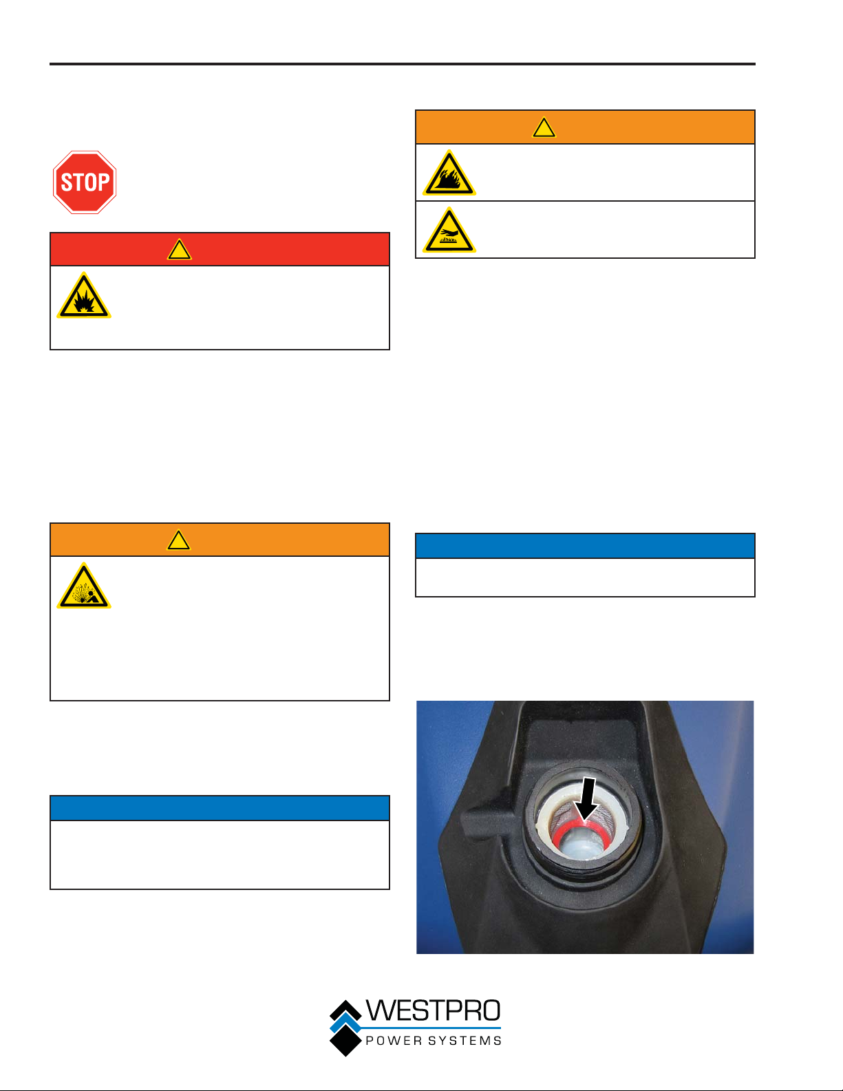
6. Slowly add gasoline into the fuel tank. Be very
careful not to overfill the tank. The gasoline level
should NOT be higher than the red ring (see Figure
26).
7. Install the fuel cap by rotating clockwise.
28
Figure 26 – Maximum Gasoline Fill Level
OPERATION
!
CAUTION
Avoid prolonged skin contact with
!
gasoline. Avoid prolonged breathing of
gasoline vapors.
STARTING THE INVERTER
For proper starting and operation of the inverter,
make sure you review the inverter features and their
descriptions starting on page 17.
Before starting the inverter, review
Safety on page 7.
OTE:N For the WH1000i, upon initial start-up or
when out of fuel, fill the inverter to the full
level. If there is only a half tank of fuel, the
fuel system will need to be primed. To prime
the fuel system, turn the engine/fuel control
switch to the ON position and pull the recoil
handle 5 to 6 times
Before attempting to start the inverter, verify the
following:
x The engine is filled with engine oil (see Checking
Engine Oil – WH1000i on page 33).
x The inverter is situated in a proper location (see
Location Selection on page 23).
x The inverter is on a dry surface (see Weather and
Dry Surface on page 23).
x All loads are disconnected from the inverter (see No
Connected Loads on page 23).
x The inverter is properly grounded (see Grounding
the Inverter on page 23).
!
DANGER
Never use the inverter in a location
that is wet or damp. Never expose the
inverter to rain, snow, water spray or
standing water while in use. Protect
the inverter from all hazardous weather
conditions. Moisture or ice can cause a
short circuit or other malfunction in the
electrical circuit.
Never operate the inverter in an
enclosed area. Engine exhaust
contains carbon monoxide. Only
operate the inverter outside and away
from windows, doors and vents.
NOTICE
The engine is equipped with a low oil shutdown
switch. If the oil level becomes low, the engine will
shut down and will not start until the oil is filled to the
proper level.
Be sure the engine has the proper oil level before
using. Failure to verify that the engine has the proper
oil level could result in engine damage.
Disconnect all loads from the inverter before starting.
Failure to verify all loads are disconnected prior to
starting the inverter could result in damage to the
connected appliances.
OTE:N There are key areas that need to be
addressed when starting the inverter. These
key areas are highlighted in yellow.
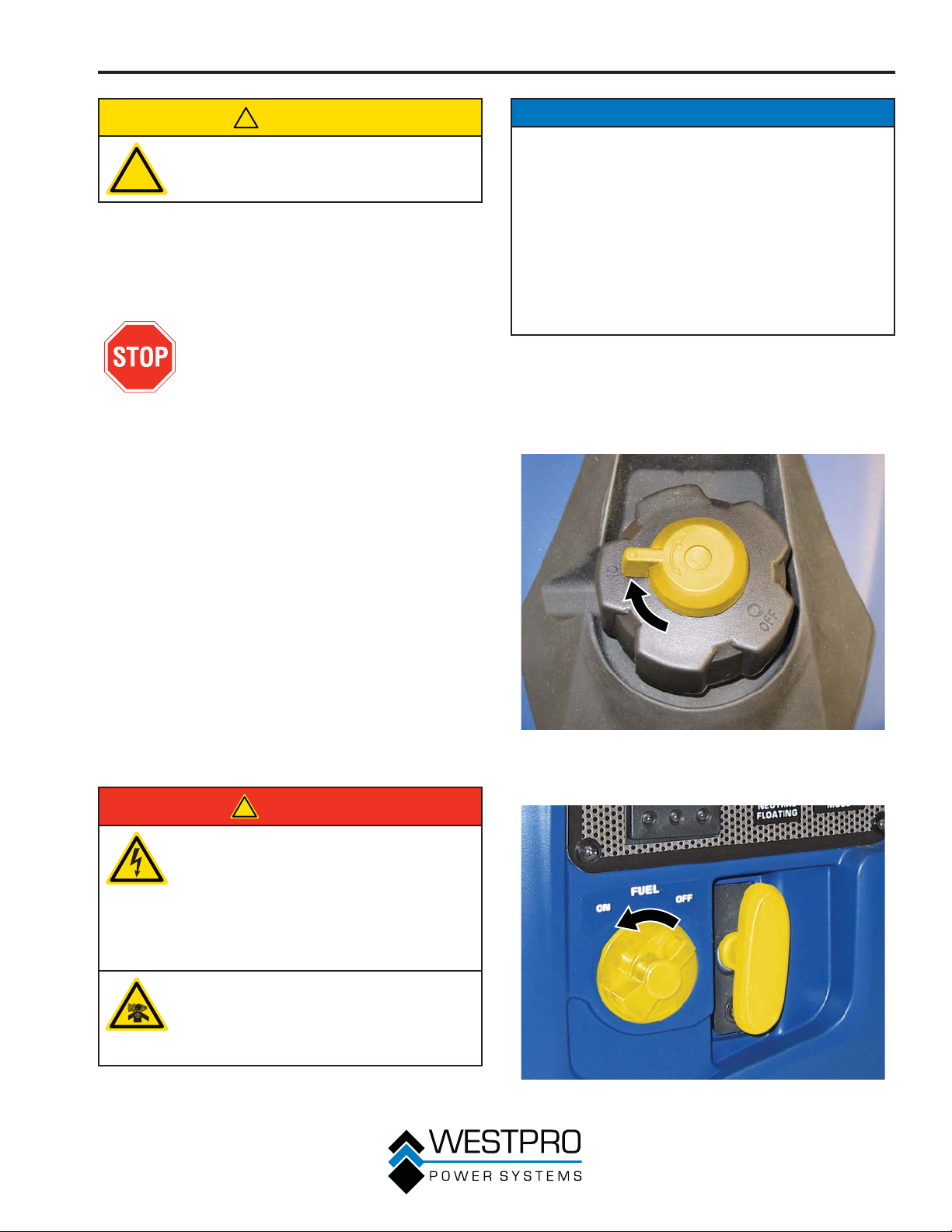
1. Turn the fuel tank vent to the ON position (see
Figure 27).
Figure 27 – Fuel Tank Vent
2. Turn the engine/fuel control switch to the ON
position (see Figure 28).
Figure 28 – Engine/Fuel Control Switch (WH1000i
Shown)
29
 Loading...