

Page 1

INSTRUCTION MANUAL
TR18361
GASOLINE CHAIN SAW
Note: Before using our chain saws. please read this
manual carefully to understand the proper use of
your unit. Keep this manual handy.
3,000
rpm
ML
550
FUEL TANKFUEL TANK
0.325
CHAINCHAIN
20
INCHES
GUIDE BAR
GUIDE BAR
61
ENGINEENGINE
CC
Page 2

Instructions contained in warning swith in this manual marked with a symbol
concern critical point swhich must be taken into consideration to prevent possible
serious bodily injury, and fort his reason you are requested to read all such
instructions carefully and follow them without fail.
This mark indicates instructions which must be followed in order to prevent
accident swhich could lead to serio us bodily injury or death.
This mark indicates instructions which must be followed, or it leads to mechanical
failure, breakdown, or damage.
This mark indicates hints or directions useful in the use of the product.
NOTES ON TYPES OF WARNINGS IN THE MANUAL
SAFETY FIRST
WARNING
IMPORTANT
!
NOTE
CONTENTS
1.PARTS LOCATION..............................................................................2
2.WARNING LABELS ON THE MACHINE.............................................2
3.SYMBOLS ON THE MACHINE............................................................3
4.SAFETY PRECAUTIONS....................................................................3
5.INSTALLING GUIDE BAR AND SAW CHAIN.....................................7
6.FUEL AND CHAIN OIL........................................................................9
7.OPERATING ENGINE.........................................................................10
8.SAWING...............................................................................................14
9.MAINTENANCE...................................................................................16
10.MAINTENANCE OF SAW CHAIN AND GUIDE BAR........................18
11.SPECIFICATIONS.............................................................................20
Page 3

1. PARTS LOCATION
2. WARNING LABELS ON THE MACHINE
(1)Read owner ’s m a n u a l before operating t h i s machine.
(2)We a r head, eye a n d ear protection.
(3)Use the chain s a w with two h a n d s
(4)Warning! kickback is danger
(5)Warning/Attention
!
1. Front guard
2. Starter knob
3. Air cleaner
4. Choke knob
5. Throttle interlock
6. Rear handle
7. Throttle trigger
8. Engine switch
9. Fuel tank
10. Oil tank
11. Front handle
12. Saw chain
13. Guide Bar
Page 4

Never remodel the p roduct. We w o n ’ t warrant the m a c h i n e , if you u s e the
remodeled product o r you don’t o b s e r v e the proper u s a g e written in t h e
manual.
For safe operation and maintenance, symbols are carved in relief on the machine.
According to these indicafions, please be careful not to make a mistake.
(a).The port to refuel the “MIX GASOLINE”
Position: fuel tank cap
(b).The port to refuel the “CHAIN OIL”
Position: oil cap
(c).The indication regarding the switch. Flipping
the engine
switch to the “O” (STOP) direction, the engine stops.
Position: rear-leftof the unit
(d).The indication regarding the choke.
Pulling out the choke knob, the choke closes.
Position: rear-right of the unit
(e).The indication regarding the chain oil adjuster nut.
“MIN” direction-the oil flow decrease
“MAX” direction-the oil flow increase
Position: bottom of the clutch side
(f).The position of H-needle
The position of L-needle
The position of idle adjusting sc
rew
Position: rear-left of the unit
a. Read this owner’s manual carefully to understand
how to operate this unit properly.
b. You should never use the product when under the influence
of alcohol, when suffering from exhaustion or lack of sleep,
when suffering from drowsiness as a result of having
taken cold medicine, or at any other time when a possibility
WARNING
3. SYMBOLS ON THE MACHINE
4. SAFETY PRECAUTIONS
BEFORE USING THE MACHINE
(a)
(b)
(d)
(e)
(f)
(c)
Page 5

exists that your judgment might be impaired or that you might
not be able to operate the machine properly and in a safe
manner.
c. Avoid running the engine indoors. The exhaust gases contain
harmful carbon monoxide.
d. Never use the product under circumstances like those
described below:
1.When the ground is slippery or when other conditions exist
which might make it not possible to maintain a steady posture
2.At night, at times of heavy fog, or at any other times when
your field of vision might be limited and it would be difficult to
gain a clear view of the area.
3.During rain storms, during lightning storms, at times of strong
or gale-force winds, or at any other times when weather
conditions might make it unsafe to use this product.
e. when u
sing this product for the first time, before beginning
actual work, leam to handling it from skilled worker.
f. Lack of sleep, tiredness, or physical exhaustion results in lower
attention spans, and this in turn leads to accidents and injury.
Limit the amount of time of using the machine continuously
to somewhere around 10 minutes per session, and
take 10~20 minutes of rest between work sessions. Also try to
keep the total amount of work performed in a single day under 2
hours o
r less.
g. Be sure to keep this manual handy so that you may refer to it
later whenever any questions arise.
h. Always be sure to include this manual when selling, lending, or
otherwise transferring the ownership of the product.
I. Never allow children or anyone unable to fully understand the
directions given in this manual to use this product.
a. When using the product, you should wear proper clothing and
protective equipments as follows.
b. And you should carry with you.
1.Att
ached tools and files.
2.Properly reserved fuel and chain oil.
(1) Helmet
(2) Protection goggles or face Protector
(3) Thick work gloves
(4) Non-slip-sole work boots
(5) Ear protectors
WORKING GEAR AND CLOTHING
Page 6

3.Things to notify your working area (Rope, warning signs)
4.Whistle (for collaboration or emergency)
5.Hatchet or saw (for removal of obstacles)
c. Never use the product when wearing pants with
loose cuffs, when wearing sandals, or when barefoot.
a. The engine of this product is designed to run
on a mixed fuel which contains highly flammable
gasoline. Never store cans of fuel or refill
the fuel tank in any place where there is a boiler
stove, wood fire, electrical sparks, we
lding sparks,
or any other source of heat or fire which might ignite the fuel.
b. Smoking while operating the product or refilling its fuel tank is
extremely dangerous. Always be sure to keep lit cigarettes away from
the product at all times.
c. When refilling the tank always turn off the engine first and take a careful
look around to make sure that there are no sparks or open flames
anywhere nearby before refueling.
d. If any fuel spillage occurs during refueling, use a dry rag to w
ipe up
spills before turning the engine back on again.
e. after refueling, screw the fuel cap back tightly onto the fuel tank and
then carry the product to a spot 3 m or more away from where it was
refueled before turning on the engine.
Check working place, the cutting object and cutting direction.
If there is obstacle, remove it.
Never start cutting until you have a clear work area, secure footing
and a planned retreat path from the falling tree.
Use caution and keep bystanders and
animals out of the working area
whose diameter is 2.5 times of the cutting object.
Inspect the machine for worn, loose, or damaged parts. Never operate
the machine that is damaged, improperly adjusted, or is not completely
and securely assembled. Make sure that the saw chain stops moving
when the throttle control trigger is released.
Always hold the machine firmly with both hands when the engine is
running. Use a firm grip with thumb and fingers encircling the
handles.
Keep a
ll parts of your body away from the machine when the engine
running.
WORKING CONSIDERING HANDLING OF FUEL
BEFORE STARTING ENGINE
WHEN STARTING THE ENGINE
Page 7

Before starting the engine, make sure the saw chain is not contacting
anything.
Keep the handles dry, clean and free of oil or fuel mixture.
Never touch the muffler, spark plug or other metallic parts of the engine
while the engine is in operation or immediately after stopping the
engine. Doing so could result in serious bums or electrical shock.
Use extreme caution when cutting small size brush and saplings
because slender material may catch the saw chain and be whipped
toward you or pull you off balance.
When cutting a limb that is under tension,
be alert for spring back to
that you won’t be struck when the tension in the wood fibers is released
check the tree for dead branches that could fall during the felling
operation.
Always shut of the engine before setting it down.
Kickback may occur when the nose or tip of the guide bar touches
an object, or when the wood closes in and pinches the saw chain in
the cut. Tip contact in some cases may cause a lightning fast
reverse reaction, kicking the guide bar up and back towards the
oper
ator. Pinching the saw chain along the top of the guide bar may
push the guide bar rapidly back towards the operator. Either of
these reactions may cause you to lose control of the saw which
could result in serious personal injury.
Do not rely exclusively on the safely devices built into your saw. As
a chain saw user you should take several steps to keep cutting jobs
free from accident or injury.
With a basic understanding of kickback you can reduce or
eliminate the element of surpr
ise. Sudden surprise contributes
to accidents.
Keep a good grip on the saw with both hands, the right hand
on the rear handle, and the left hand on the front handle,
when the engine is running. Use a firm grip with thumbs and
fingers encircling the chain saw handles. A firm grip will help
you reduce kickback and maintain control of the saw.
Make certain that the area in which you are cutting is free from
obstructions Do not let the nose of the guide bar contact a log,
branch, or any othe
r obstructions which could be hit while you
are operating the saw.
Cut at high engine speeda.
OPERATION
KICKBACK SAFETY PRECAUTIONS FOR CHAIN SAW USERS
WARNING
!
(1)
(2)
(3)
(4)
Page 8

Do not overreach or cut above shoulder height.
Follow manufactures sharpening and maintenance
instructions for saw chain.
Only use replacement bars and chains specified by the
manufacturer or the equivalent.
In order to maintain your product in proper working order,
perform the maintenance and checking operations
described in the manual at regular intervals.
Always be sure to turn off the engine before performing
and maintenance or checking procedures.
Leave all maintenance other than the items listed in the
Owner ’s Manual to your competent servicing d
ealer.
Always carry the unit with the engine stopped, the
guide bar covered with the protector to the rare , and
muffler away from your body.
A standard saw unit package contains the items
as the items as illustrated.(F1)
Open the box and instal the guide bar and the
saw chain on the power unit as follows:
(1) P ower unit
(2) B ar protector
(3) G uide bar
(4) C hain saw
(5) P lug wrench
(6) S crewdriver for carburetor adjustment
(7) S pike and mounting screws
(5)
(6)
(7)
The metallic parts reach high temperatures
immed
iately after stopping the enging.
MAINTENANCE
TRANSPORTATION
5. INSTALLING GUIDE BAR AND SAW
CHAIN
WARNING
!
Page 9
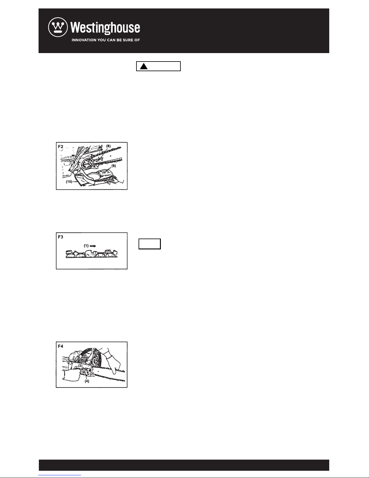
Th e s aw c h ai n h as v ery s har p edg es . Us e t hic k
pr otect ive g lov es f or s af et y.
Pull the guard towards the front handle to check
that the chain brake is not on.
loosen the nuts and remove the chain cover.
Install the attached spike to the power unit.
Gear the chain to the sprocket and, while fitting
the saw chain around the guide bar, mount the
guide bar to the power unit. Adjust the position
of chain tensioner nut on the chain cover to the
lower hole of guide bar.(F2)
Pay attention to the correct direction of the saw
chain.(F3)
Fit the chain cover to the power unit and fasten th
e
nuts to finger tightness.
While holding up the tip of the bar, adjust the chain
tension by turning the tensioner screw until the tie
straps just touch the bottom side of the bar rail.(F4)
Tighten the nuts securely with the bar tip held up
(12~15N.m). Then check the chain for smooth
rotation and proper tension while moving it by hand.
If necessary, readjust with the chain cover loose.
Tighten the tensioner screw.
(8) Hole
(9) Tensioner nut
(10) Chain cover
(1)Mov ing Direct ion
(2) Loo sen
(3) Tig h ten
(4) Tensi oner scr ew
1.
2.
3.
4.
5.
6.
7.
8.
NOTE
WARNING
!
Page 10
A new chain will expand its length is the beginning of
use. Check and readjust the tension frequently as a
loose chain can easily derail or cause rapid wear of itself
and the guide bar.
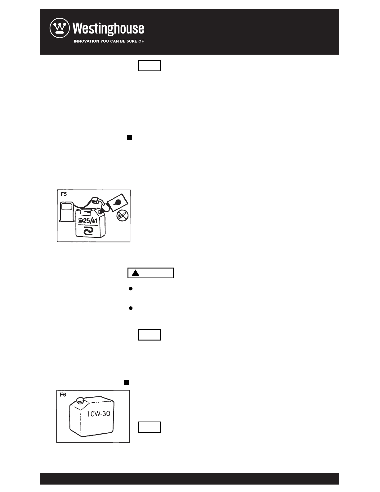
Mix a regular gasoline (leaded or unleaded, alcohol-free)
and a quality-proven motor oil for air cooled 2 cycle
engines.
Keep open flam es aw ay fro m the area wh ere fuel is
han d l ed or s to r ed.
Mix and store fuel only in an ap p ro v ed gas ol i ne
container.
Most engine troubles are caused, directly or indirectly,
by the fuel used on the machin
e. Take special care not
to mix a motor oil for 4 cycle engines.
Us e m o tor o i l S AE# 10 W ~3 0 a l l y ear ro und
or S A E # 3 0~ # 40 in su mme r a n d S AE# 20 i n
wi nte r.
Do n o t u s e w ast ed o r r e ge n er a ted o i l t hat
ca n c a use d a ma g e t o t he o il pu m p.
6. FUEL AND CHAIN OIL
CHAIN OIL
FUEL
Rec om mended mi x in g rati o :
Condition Gasoline : Oil
Up to 20 hours use 20:1
After 20 hours use 25:1
Gasoline liters 1 2 3 4 5
2-cycle oil ml. 40 80 120 160 200
25: 1 Mix Chart
NOTE
NOTE
NOTE
WARNING
!
Page 11
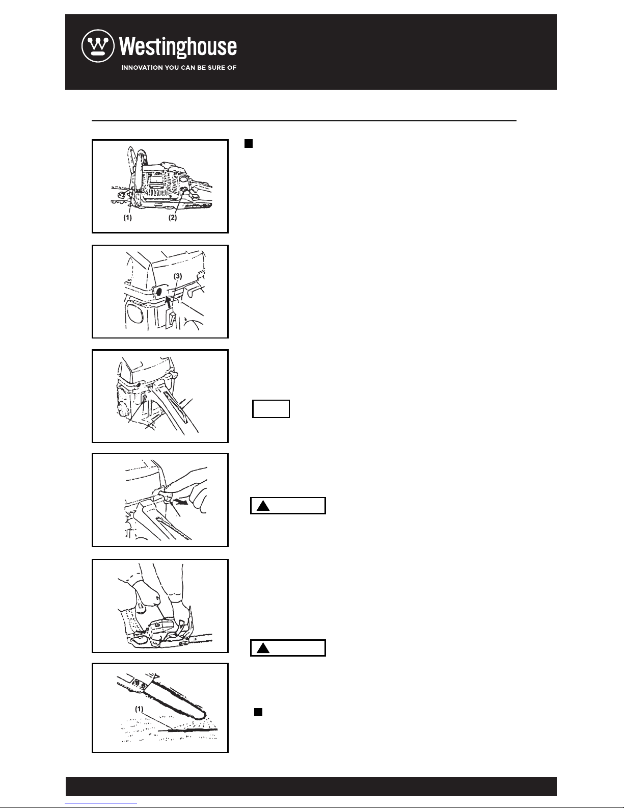
Fill fuel and chain oil tanks respectively,
and tighten the caps securely.(F7)
Put the switch to “l” position.(F8)
While holding the throttle lever together with the
throttle interlock, push in the side throttle lock button
and release the throttle lever to hold it at the starting
position.(F9)
(1) Chain oil
(2) Fuel
(3) Switch
(4) Throttle lever
(5) Throttle interlock
(6) Choke knob
Pull out the choke knob to the closed position.(F10)
When restarting immediately after st
opping the
engine, leave the choke knob at the open position.
While holding the saw unit securely on the
ground, pull the starter rope vigorously.(F11)
Do not st art the en gi ne while hangi n g the ch ain
saw wi th a han d. The saw c h ain m ay t ou ch yo u r
bod y. It’s v ery dan gero u s.
When engine has ignited first, push in the choke
knob and pull the starter again to start the engine
Allow the engine to warm up with the throttle lever
pulled slightly.
Keep clear of the saw chain as it will start
r
otating upon starting of engine.
After starting the engine. run the chain at medium
speed and see if chain oil is scattered off as shown
7. OPERATING ENGINE
STARTING ENGINE
CHECKING OIL SUPPLY
1.
2.
3.
4.
5.
6.
7.
F7
F8
F9
F10
F11
F12
NOTE
(3)
(4)
(5)
(6)
WARNING
!
WARNING
!
Page 12
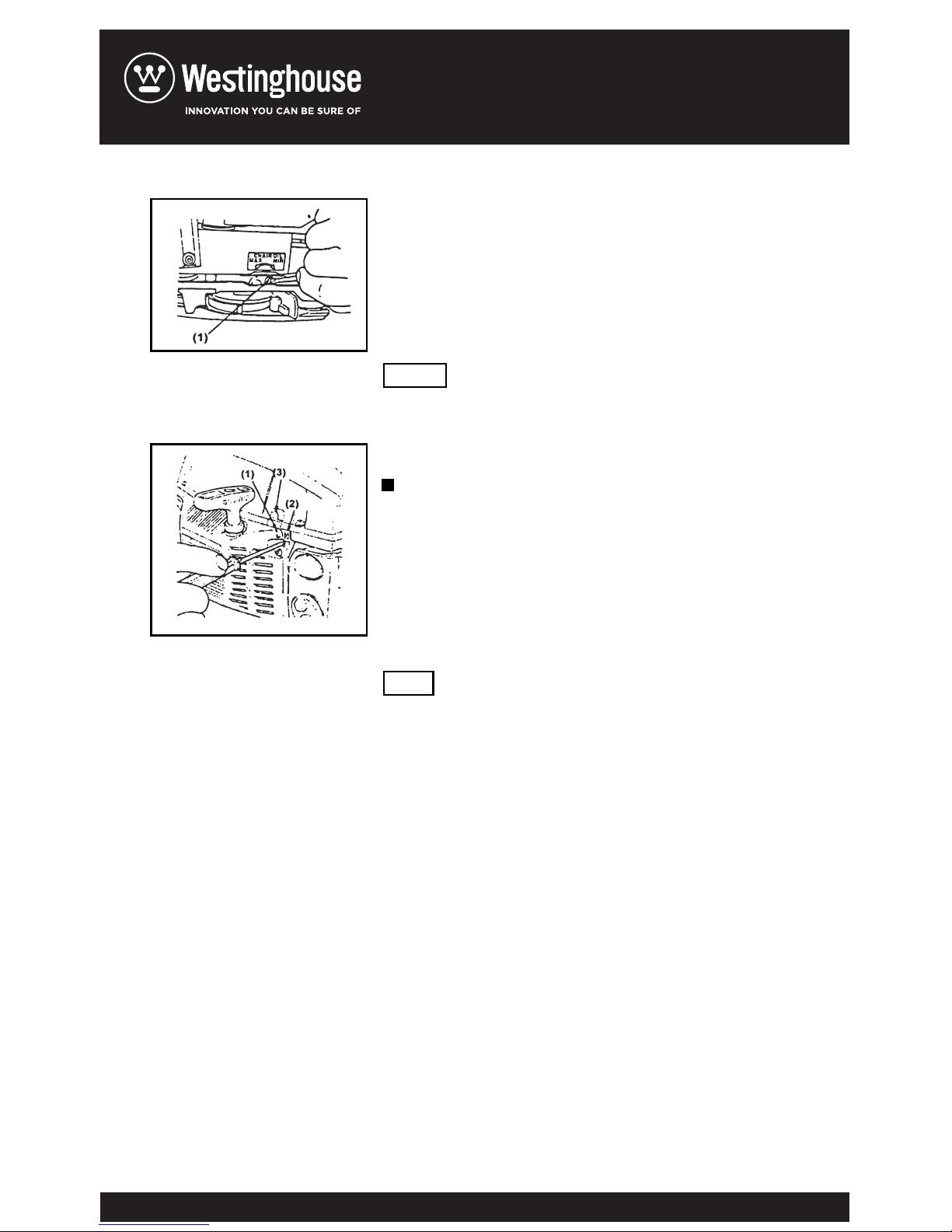
in the figure.(F12)
(1)Chain oil
The chain oil flow can be changed by inserting
a screwdriver in the hole on bottom of the clutch
side. Adjust according to your work conditions.
(F13)
The oil tank should become nearly empty by the
time fuel is used up. Be sure to refill the oil tank
every time when refueling the unit.
The carburetor on your unit has been factory
adjusted, but may require fine tuning due to change
in operating conditions. Before adjusting the
carburetor, make sure
that provided are clean
air/fuel filters and fresh, properly mixed fuel. When
adjusting, take the following steps:
Be sure to adjust the carburetor with the
bar chain attached
1.Stop engine and screw in both H and L
needles until they stop. Never force. Then set them
back the initial number of turns as shown below.
Start engine and allow it to warm up at
half-throttle.
Turn L needle slowly clockwise to find a position
where idling speed is maximum, then set the
needle back a quarte
r(1/4) turn
counterclockwise.
Turn idle adjusting screw(T) counterclockwise
to that saw chain does not turn. If idling speed is
too slow, turn the screw clockwise.
ADJUSTING CARBURETOR(F14)
(1) Ad j us ter
3
H needle: 1 /
8
1
L need l e: 1 /
4
2.
3.
4.
NOTE
NOTE
F13
F14
Page 13
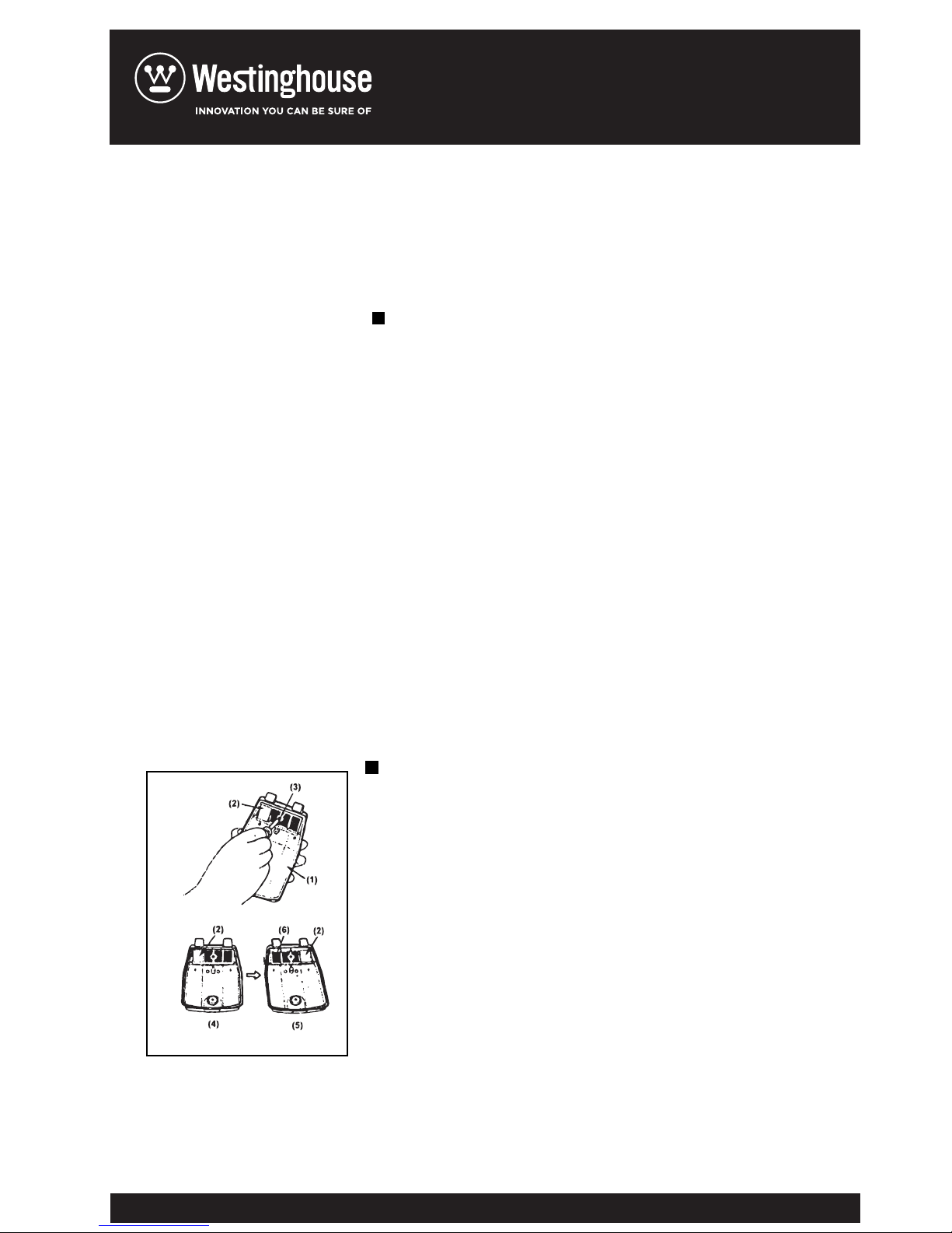
5. Make a test cut and adjust the H needle for best
cutting power, not for maximum speed.
(1) L n eed l e
(2) H need l e
(3) Idle ad just i ng s c rew
Operating the chain saw in temperatures of 0-5°C
at times of high humidity may result in ice forming
within the carburetor, and this in turn may cause
the output power of the engine to be reduced or
for the engine to fail to operate smoothly. This
product has accordingly been designed with a
ventilation hatch the back of the air cleaner cover
to allo
w warm air to be supplied to the engine and
to there by prevent icing from occurring.
Under normal oircumstances the product should
be used in normal operating mode, i.e., in the
mode to which it is set at the time of shipment.
However when the possibility exists that icing may
occur, the unit should be set to operate in
anti-freeze mode before use.(f15)
Flip the engine switch to turn off the engine.
Remove the air cleaner cover from the
cylinder cover
Loosen a screw and remove the s
creen on the
back of the air cleaner cover.
Reattach the screen right side left so as to the
anti-icing plate is on the right. Reinstall the
cover.
(1) Air cl ean er c over
(2) Ant i -ic i ng p l ate
(3) Screw
(4) Norm al o p eratin g m o de
(5) Ant i -fr eeze mod e
(6) Screen
CARBURETOR ANTI-FREEZE MECHANISM
HOW TO SWITCH BETWEEN OPERATING
MODES (F15)
1.
2.
3.
4.
F15
Page 14
Con t inui n g to u se t h e pro d uct i n ant i -fre e ze
mod e e v en w h en te mp erat u re s ha v e ris e n
and re t ur ned t o nor m al m a y res ul t in the
eng i ne f a il ing t o sta r t pr o perly or in the
eng i ne f a il ing t o ope r ate a t its no r mal s pe ed,
and fo r th i s re a son y o u sh o uld a lw ays b e
sur e t o re t urn t he un i t to nor ma l op e ra ting
mod e i f th e re i s no da n ger o f ici n g oc c ur ring .
When using the saw with the anti-freeze mode,
frequently check the screen and keep it clean of
saw dust.
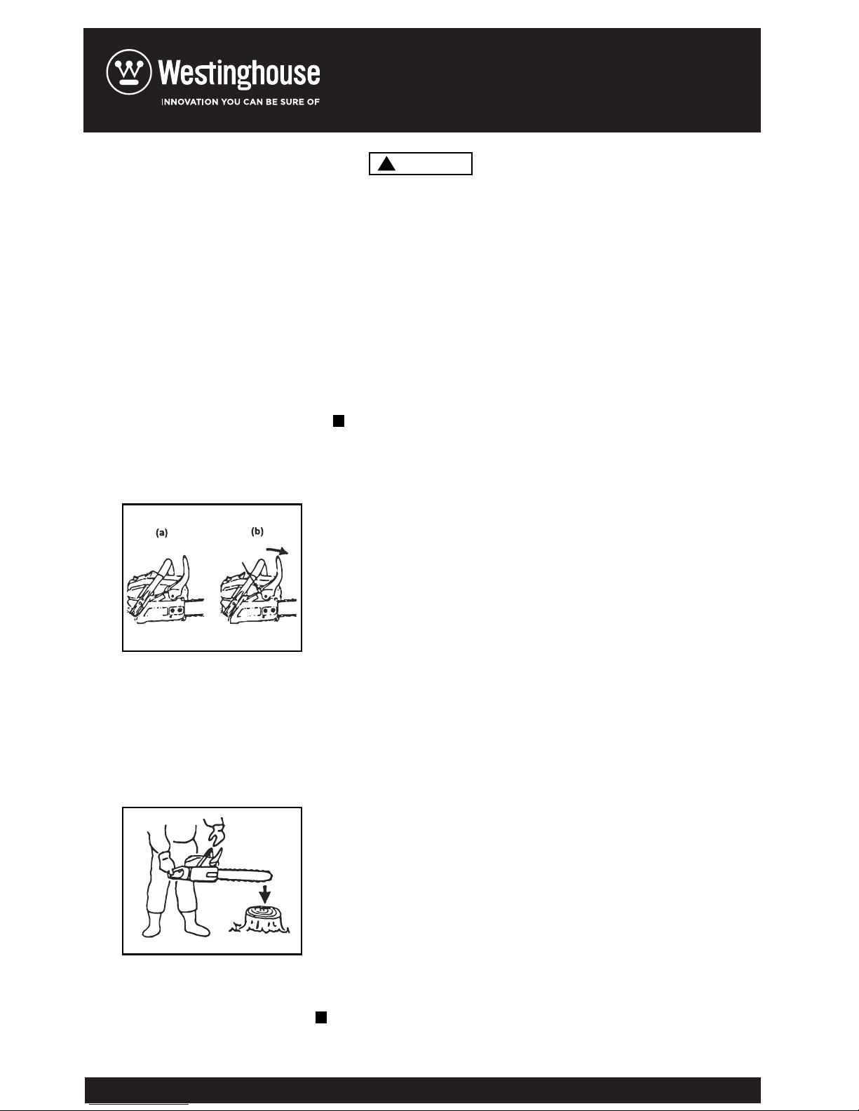
This machine is equipped with an automatic brake to
stop saw chain r
otation upon occurrence of kickback
while in saw cutting operation. The brake is
automatically operated by inertial force which acts on
the weight fitted inside the front guard. This brake can
also be operated manually with the front guard turned
down to the guide bar.(F16)
To release brake, pull up the front guard toward the
front handle till”click”sound is head.
Be sure to confirm brake operation on the daily
inspection
How to confirm
(1)Turn off the engine.
(2)Holding the chain saw horizontally, release your
hand from the front handle, hit the tip of the guide bar
to a st
ump or a piece of wood, and confirm brake
operation. Operating level varies by bar size.(F17)
In case the brake is not effective, ask our dealer
inspection and repairing. The engine, If being dept
rotated to high speed with the brake engaged, heats
the clutch, causing a trouble, When the brake is
operated while in operation, immediately release
your fingers from the throttle lever and keep the
engine idling.
1.Release the throttle lever to allow the engine idling
CHAIN BRAKE
STOPPING ENGINGE
[Caution]
F16
F17
WARNING
!
Page 15
for a f e w mi n ut es .
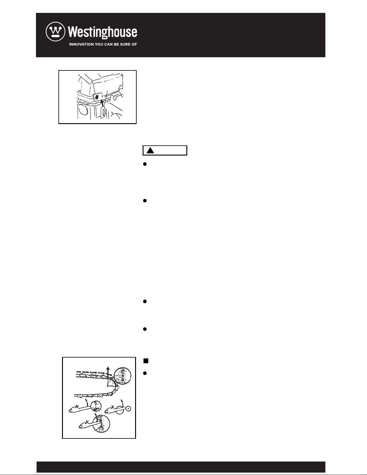
2.P u t th e sw i t ch to the “O” ( ST O P) po s it io n.(F1 8 )
(1) Switch
Bef o r e pro c ee ding t o you r job , re a d
Ope r a tion” sec t i on. I t is reco m me nd ed to fir s t
pra c t ice s a wi ng ea s y log s . This a lso h e lp s you
get accu s to me d to y our u n it .
Alw a y s fol l ow th e sa f e ty re g ul at ions. T he ch a in
saw must onl y be u se d for cut t i ng wo o d. It is
for b i dden t o out othe r ty p es of mate r ia l.
Vibr a t ions a nd ki c kb ac k var y wi t h di f f er en t
mat e r ials a nd th e re q u ireme n ts of the s af ety
reg u l ation s wo
uld not b e res p ec te d. Do not use
the chai n sa w as a le v er fo r lif t in g, mo v in g or
spl i t ting o bj ects. Do n o t loc k it over fix e d
sta n d s. It is f or bi dden t o hit c h too l s or
app l i catio n s to t he P.t.o. tha t are not spec i fi ed
by t he ma n u factu r er.
It i s not nece s sa ry to for c e th e sa w int o the cut .
App l y on l y lig h t pres s ur e whi l e run n in g the
eng i n e at f ull t h ro ttle.
Whe n the saw chai n is caug h t in t he cu t , do not
att e m pt to pul l it o ut by for c e , but use a we d ge
or a le v e r to o pe n the way.
“Fo r Saf e
Thi
s saw is equipped with a chain brake that will
stop the chain in the event of kickback if operating
properly. You must check the chain brake operation
before each usage by running the saw at full the
throttle for 1-2 seconds and pushing the front hand
guard forward. The chain should stop immediately
with the engine at full speed. If the chain is slow to
stop or does not stop, replace the brake band and
clutch drum before use.
GUARD AGAINST KICKBACK (F19)
8.SAWING
F19
F18
(1)
WARNING
!
Page 16
It is extremely important that the chain brake be
checked for proper operation before each use and
that the chain be sharp in order to maintain the
kickback safety level of this saw. Removal of the
saf ety dev ices. In adequate mainten ance, or
incorrect replacement of the bar or chain may
increase the risk or serious personal injury due to
kickback.
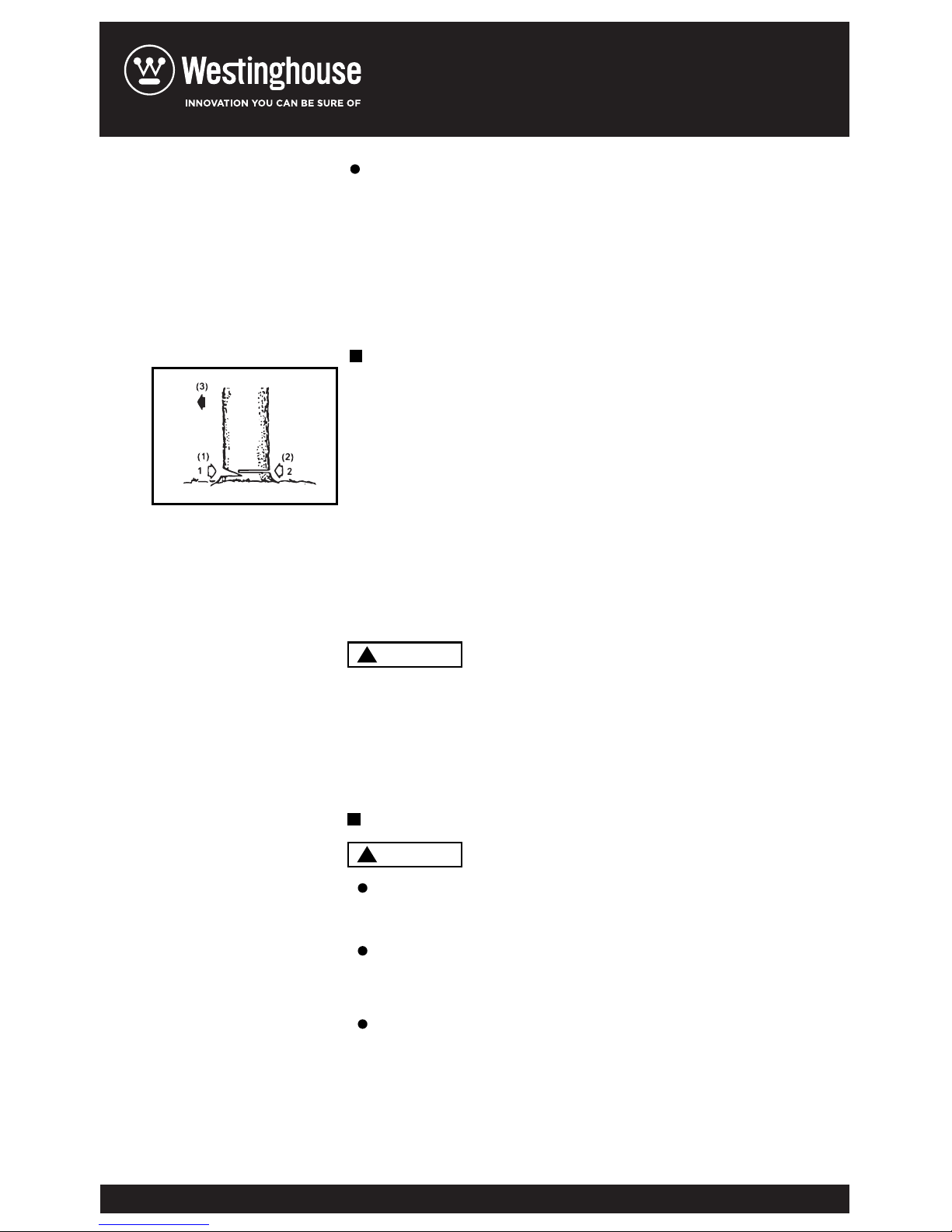
Decide the felling direction considering
the wind, lean of the tree, location of heavy
branches, ease of job after felling and other
factors
While clearing the area aro
und the tree, arrange
a good foothold and retreat path.
Make a notch cut one-third of the way into the
tree on the felling side.
Make a felling cut from the opposite side of the
notch and at a level slightly higher than the
bottom of the notch.
Before starting work, check the direction of bending
force inside the log to be cut. always finish cutting
from the opposite side of bending direction to prevent
FELLING A TREE(F20)
1.
2.
3.
4.
Bucking and Limbing
F20
Be alert to the rolling over of a cut log.
Especially when working on a slope, stand on
the uphill side of the log.
Follow the instructions in”For safe Operation”
to avoid kickback of the saw.
Always ensure your foothold. Do not stand on
the log.
When you fell a tree, be sure to warn your
neighboring workers of the danger.
(1) Notch cut
(2) Felling cut
(3) Felling direction
WARNING
!
WARNING
!
Page 17
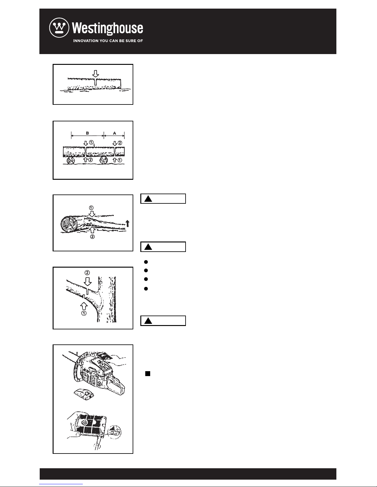
the g ui de ba r fr o m bein g cau g ht in the cut .
Saw d ow n half w ay, th e n roll the
log o ve r and c ut fro m th e op p os it e side .
In a r ea A , saw up f ro m the b ot to m one- t hi rd an d
fini s h by s a wi ng do w n from the top. In a re a B, s a w
down fro m the top one - th ir d and f in is h by s a wi ng up
from the bott o m.
Firs t ch e ck to whic h si d e the l im b is b e nt .
Then mak e the ini t ia l cut f ro m the b en t side and
fini s h by s a wi ng fr o m the o pp os it e side .
Be a l er t to t h e spri n gi ng ba c k of a cut lim b .
Prun i ng of Sta n d ing Tree(F 2 4)
Cu
t up fro m th e bot t om , fini s h down fro m th e top .
Do n o t use a n unst a bl e foot h ol d or l a dd er.
Do n o t over r ea ch .
Dot n ot cu t ab o ve sh o u lder h e ig ht .
Alwa y s use y ou r both han d s to g r ip th e saw.
Befo r e clea n in g, in s pe ct in g, or repa i ri ng you r
unit , ma k e sure that eng i ne ha s sto p pe d and i s
cool . Di s co nn ec t the s pa rk pl u g to p r ev en t
acci d en ta l star t in g.
Dust on t he cl e an er su r fa ce ca n be r em oved b y
tapp i ng a c or ne r of t h e clea n er ag a in st a h ar d
surf a ce . To clean dir t in the m es he s, sp l it th e
clea n er
in. o ha l ve s and b ru sh in gas o li ne . When usin g
comp r es se d air, bl o w from the insi d e. (F 25 )
Dism o un t the g ui de ba r an d ch e c k the
A L o g l y i n g o n t h e g r ou n d ( F2 1)
A L o g h an gi n g o ff th e g r o u n d (F2 2 )
Cu t t i n g L i m b o f F al l en Tr e e (F23 )
1.A i r f i l te r
2.Oi l i n g p o r t
MAINTENANCE AFTER EACH USE
9. MAINTENANCE
F21
F22
F23
F24
F25
WARNING
!
WARNING
!
WARNING
!
Page 18
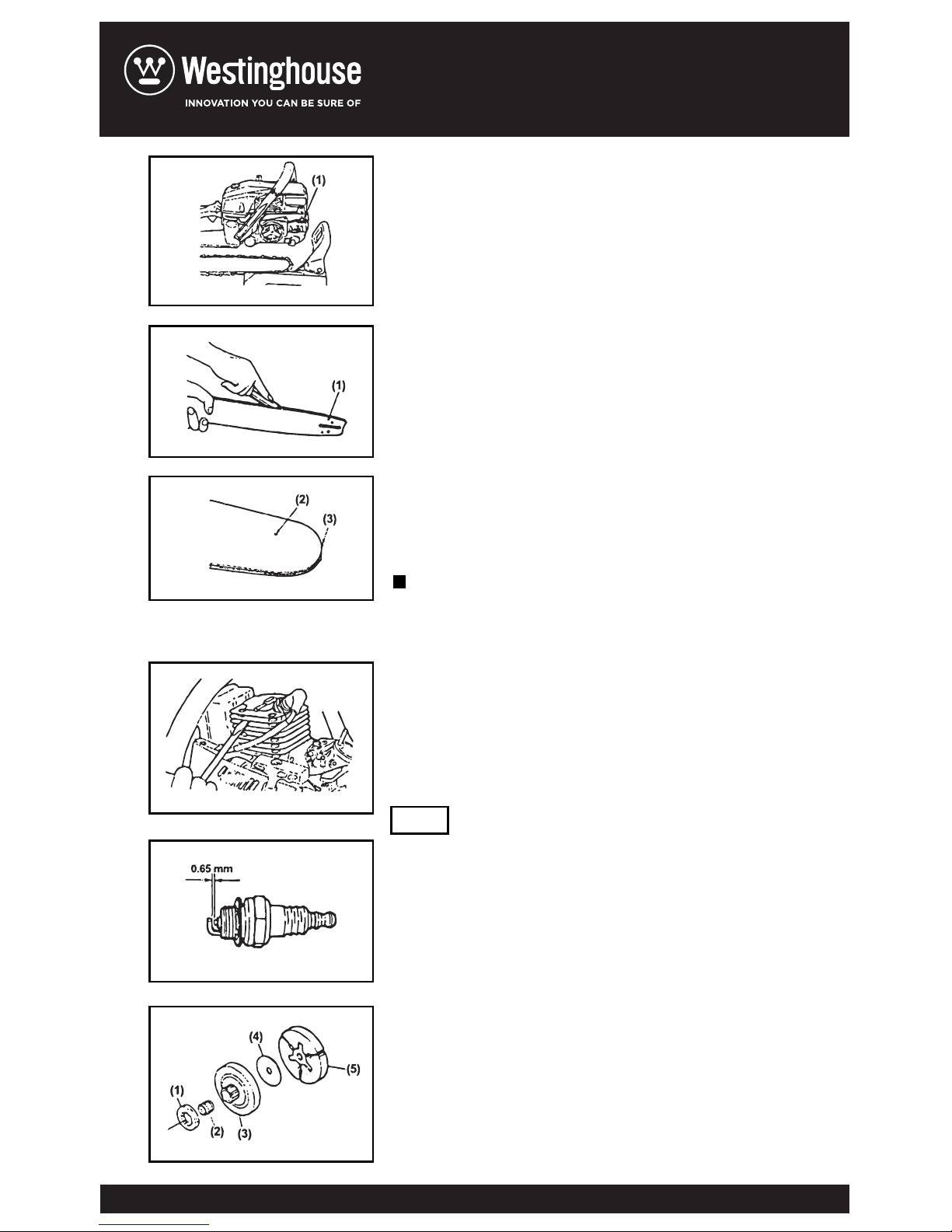
oili n g pot f or cl o gg in g.(F26 )
When the guide bar is dismounted, remove
Saw dust in the bar groove and the oiling port.(F27)
Grease the nose sprocket from the feeding
port on the tip of the bar.(F28)
Check for fuel leakage and loose fastenings and
damage to major parts.
especially handle joints and guide bar mounting. If
any defects are found, make sure to have them
repaired before operating again.
Dust clogging between the cylinder fins will cause
overheating of the engine Periodically check and
clean the cylinder fins after removing the air
cleaner and the cylinder co
ver.
When installing the cylinder cover, make sure that
switch wires and grommets are positioned
correctly in place.(F29)
Be sure to black the air intake hole.
Clean the electrodes with a wire brush and reset the
gap to 0.65 mm as necessary.
Check for cracks and for excesslve wear interfering
with the chain drive. If the wearing is found
obviously, replace it with new one. Never fit a new
chain on a worn sprocket, or a worn chain on a
new sprocket.
(1) O ili ng p or t
(2) G reas e p ort
(3) S pro cket
3. Gu i de bar
4. Ot h er s
1. Cy l in d er f i ns
2. Sp ar k p l ug(F30)
3. S
pr ock et (F31)
PERIODICAL SERVICE POINTS
NOTE
F26
F27
F28
F29
F30
F31
Page 19
WARNING
!
WARNING
!
(2) N eedl e b eari n g
(3) C lut ch d rum
(4) S pac er
(5) C lut ch s hoe
4. Fu el f il ter
5. Oi l f ilt er
6. Fr o nt an d Rear d am pers
Disassemble the filter and wash with gasoline, or
replace with new on if needed.
Disassemble the filter and wash with gasoline, or
replace with new on if needed.
Replace if adhered part is peeled or crack is
observed on the rubber part.
It is very important for smooth and safe
operation to keep the cutters always sharp.
Your cutters need to be sharpened
when:
Sawdust becomes powder-like.
You need extra force to saw in.
The cut way does not go straight
Vibration increases
Fuel consumption increases
Be sure to wear safety gloves.
Make sure the saw chain in held
sccurely
Make sure the engine is stopped
Use a round file of proper size for
your chain.
Chain type: 21VB
File size: 3/16 in (4.76 mm)
Before filing:
SAW CHAIN
10.MAINTENANCE OF SAW CHAIN
AND GUIDE BAR.
Cu tt er s et ti n g s tan dard s:
(1) S pro cket
Page 20
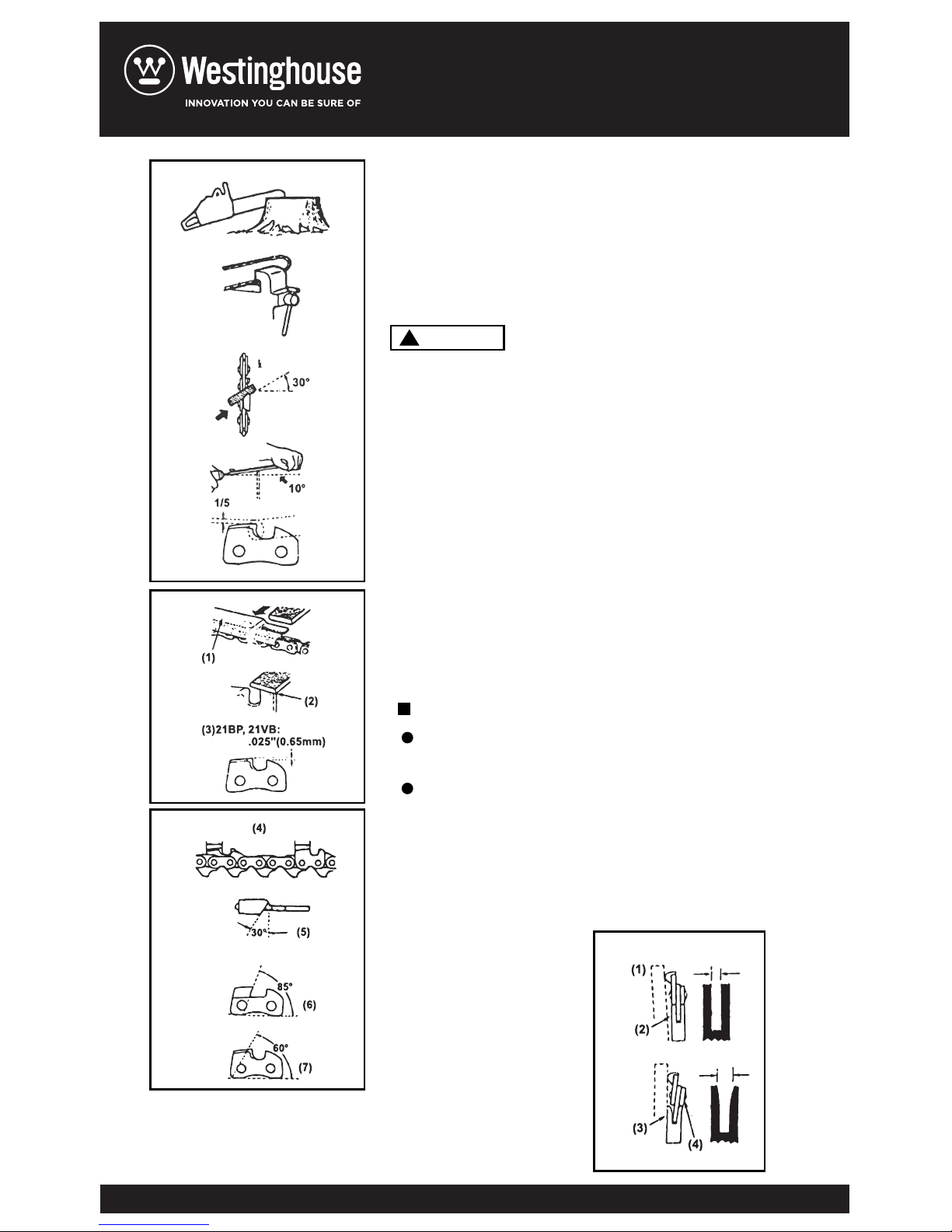
Place your file on the cutter and push
straight forward. Keep the file position
as illustrated.(F32)
After every cutter has been set, check
the depth gauge and file it to the proper
level as illustrated.(F33)
Be sure to round off the front edge to
reduce the chance of kickback or tie-strap
breakage.
Make sure every cutter has the same
length and edge angles as illustrated (F34)
Reverse the bar occasionally to
prevent partial wear.
The bar rail should always be a square.
Check for wear of the bar rail. Apply a ruler to
the bar and the outside of a cutter. If a gap is
observed between them t
he rail is normal.
Otherwise, the rail is worn. Such a bar needs
to be corrected or replaced.(F35)
GUIDE BAR
F32
F33
F34
F35
(1) Ruler
(2) Gap
(3) No gap
(4) Chain tilts
(4) Cutter length
(5) Filling angle
(6) Side plate angle
(7) Top plate cutting angle
(1) Appropriate gauge checker
(2) Make the shoulder round
(3) Depth gauge standard
WARNING
!
Page 21
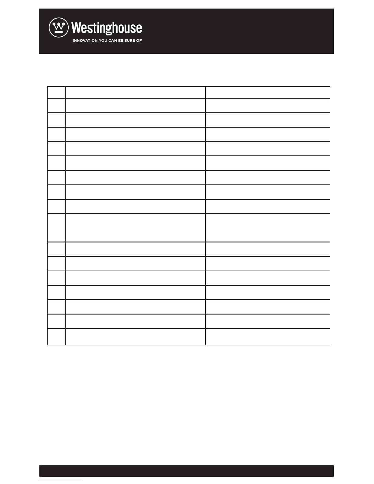
11. SPECIFICATIONS
1
2
3
4
5
6
7
8
9
10
11
12
13
14
15
16
17
4600
7.5(kg)
410 X 235 X 265(mm)
Mixture (Gasoline 25: Two-cycleoil 1)
550(ml)
Motor oil SAE#10W-30
260(ml)3
46(cm3)
1.6kw/7500rpm
10000rpm
2800rpm
7T X 0.325
0.325(in)
0.058(in)
Sprocket nose
16 18 20(in)
Automatic pump with adjuster
Chain saw Model
Mass (without guide bar and chain)
Dimensions (without guide bar and chain)
Fuel
Fuel tank capacity
Chain oil
Oil tank capacity
Engine displacement
Maximum engine power
Maximum engine speed with cutting
attachment
Maximum Engine speed at idling
Sprocket
Saw chain pitch
Saw chain gauge
Guide bar type
Guide bar size
Oil feeding system
Page 22
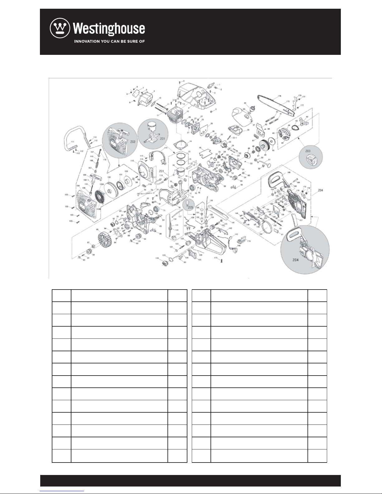
EXPLORE VIEW
1
2
3
4
5
6
7
8
9
10
11
12
13
14
spark plug
blinker
upper cover screw
upper cover screw
cylinder plastic cover
switch plug
muffler nut
muffler cover plate
screw
muffler assy
muffler gasket
muffler coupling screw
cylinder screw
cylinder
1
1
2
3
1
1
2
1
2
1
1
2
4
1
15
16
17
18
19
20
21
22
23
24
25
26
27
28
cylinder gasket
pistion ring
pistion
pistion pin snap ring
pistion pin
carburator gasket
chain catcher
chain catcher screw
turriform spring seat
turriform spring
screw
intake tube gasket
intake tube
intake
tube and gasket screw
1
2
1
2
1
1
1
1
1
1
3
1
1
4
Page 23
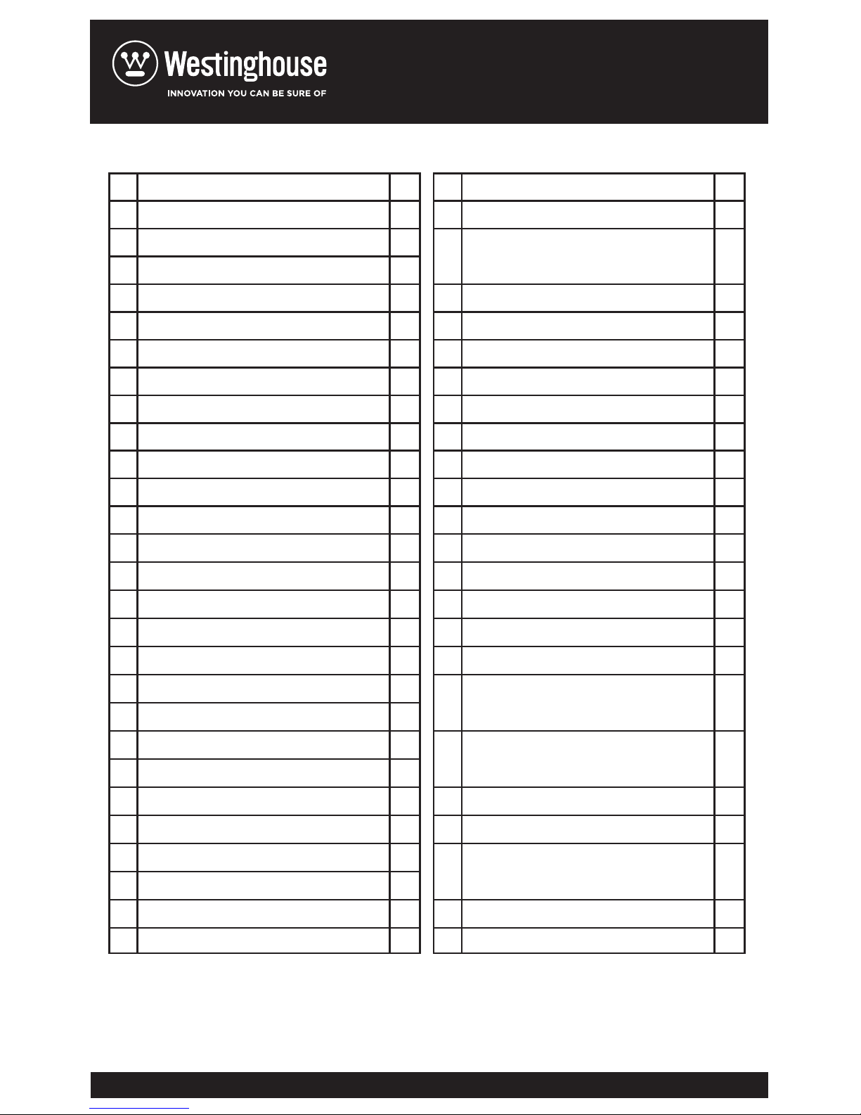
29
30
31
32
33
34
35
36
37
38
39
40
41
43
44
45
46
47
48
49
50
51
52
53
54
55
56
57
intake tube bracket
intake tube bracket gasket
intake flange
retaining ring
carburator assy
intake angle pipe
intake angle pipe stud
intake angle pipe shock absorption
carburator screw
air filter
air filter top cover
lock nut gasket
air filter lock nut
stud
body frame
clutch pullback spring
shoe block
clutch washer
clutch drum
chain wheel
clutch needle bearing
endless screw
choke knob sleeve
choker rod
c
hoker rod-shock absorption
oil bump cover screw
oil bump cover
oil outlet pipe
1
1
1
1
1
1
1
1
2
1
1
1
1
2
1
1
3
1
1
1
1
1
1
1
1
3
1
1
58
59
60
61
62
63
64
65
66
67
68
69
70
71
72
73
74
75
76
77
78
79
80
81
oil pump screw
oil pump assy
oil pump dustproof filter cotton
small seal oil
breath nipple snap spring
filter cotton
breath nipple
small plug pad
rubber cushioning pad
oil outlet cover plate
oil outlet cover plate screw
chain guiding block
right rubber cushioning pad
right crank case
pin
bearing ball
needle beari
ng circlip
small end of connecting rod-ball
bearing
crankshaft with connecting rod
assembly
woodruff key
crank case gasket
negative pressure pipe-snap ring
negative pressure pipe
negative pressure nozzle
2
1
1
1
1
1
1
3
3
1
1
2
1
1
3
2
2
1
1
1
1
1
1
1
Page 24
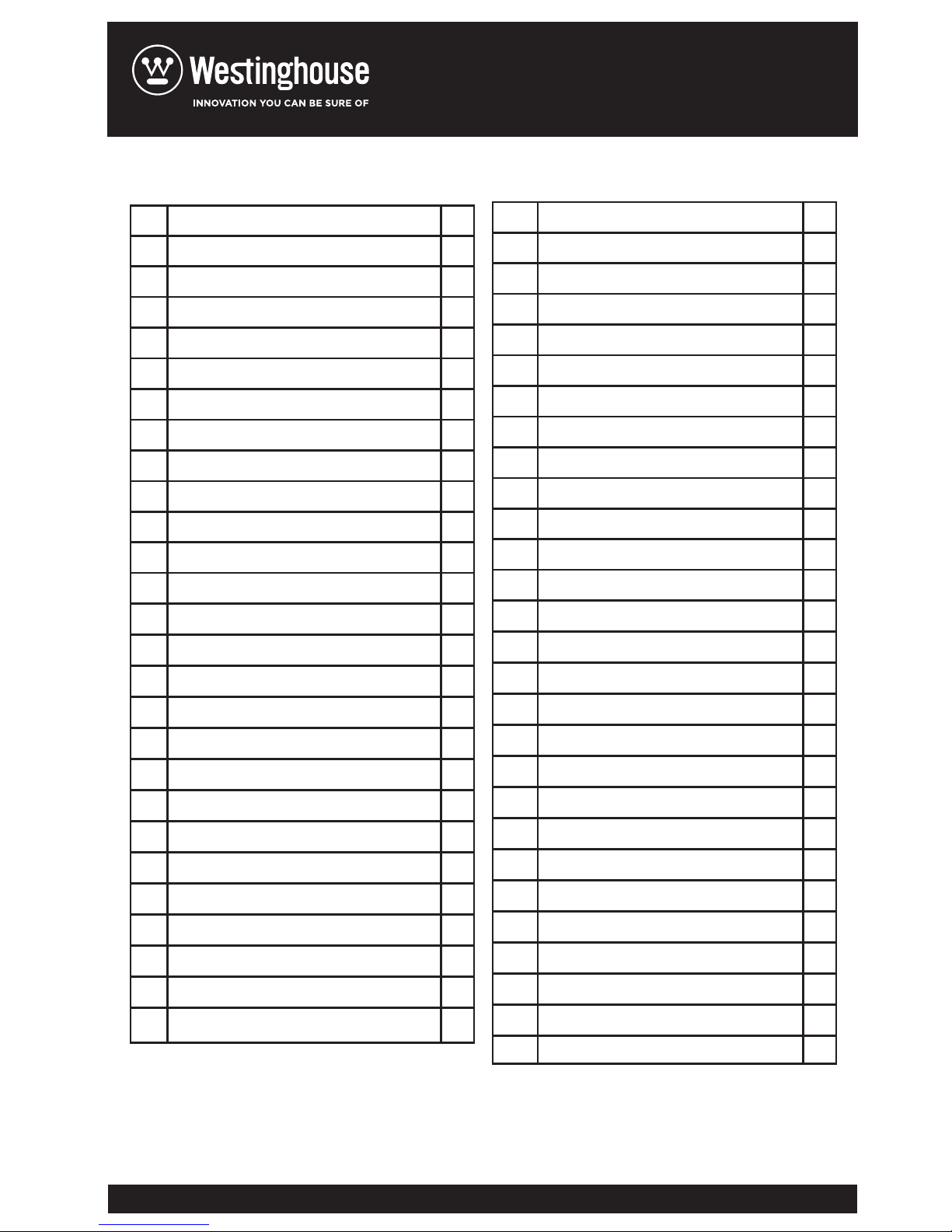
82
83
84
85
86
87
88
89
90
91
92
93
94
95
96
97
99
100
101
102
103
104
105
106
107
108
109
stop switch wire clamp
stop switch wire pressplate
idling speed regulating sleeve
circlip for hole
HL sleeve
left crank case
left rubber cushioning pad
screw
screw
big oil seal
suspension loop
oil cap gasket
oil cap
oil seal plate
oil seal plate screw
flywheel assy
flywheel nut
starter screw
starter screw gasket
pulley starter
energy stored spring
starter connecting pulley
starter spring cover
starter spring
starter housing
s
tarter housing screw
rope sleeve
1
1
1
1
1
1
1
2
3
1
2
1
1
1
2
1
1
1
1
1
1
1
1
1
1
4
1
110
111
112
113
114
115
116
117
118
119
120
121
122
123
124
125
126
127
128
129
130
131
132
133
134
135
136
137
handle inner ring
recoil spring
starter handle
starter handle gasket
rope
handle
handle screw
ignition screw
ignition assy
air deflector
LH sleeve
oil intake pipe
oil filter
fuel cap
fuel cap gasket
big dust proof cover
nut
long cushioning rubber pad
trigger pin
trigger
trigger spring
double cushioning screw
fuel tank
throttle rod
balance cover
balance valve
bala
nce housing
balance support
2
1
1
1
1
1
4
2
1
1
1
1
1
1
1
2
2
2
1
1
1
1
1
1
1
1
1
1
Page 25
138
139
140
141
142
143
144
145
146
147
148
149
150
151
152
153
154
155
156
157
158
159
160
161
162
163
164
165
fuel oil filter assy
fuel oil pipe snap ring
fuel oil pipe
oil inlet tube
fuel pipe
oil return pipe
oil pump support
rear handle
lever trigger
decorative cover
primer pump
switch
brake spring cover plate screw
brake spring cover plate
main lever
auxiliary lever
straight pin
brake strap
brake ancillary spring
brake spring
brake lever
chain brake lever pin bush
tensioning cover plate screw
tensioning cover plate
oil
baffle
tensioning driving gear
tensioning following gear
tensioning pin
1
1
1
1
1
1
1
1
1
1
1
1
4
1
1
1
3
1
1
1
1
1
2
1
1
1
1
1
166
167
168
169
170
171
172
173
174
175
176
177
178
179
180
181
182
183
184
185
186
187
188
spacer pin
split washer
spacer plate
rubber gasket
split washer
gasket
brake torsional spring
chain brake lever
chain brake lever pin
right side cover
rubber block
flange nut
rear handle screw
dustproof rubber plate
chinese bar
chain assy
screw plate screw
spike
crank shaft with connecting rod and
piston assy
starter assy
clutch assy
brake assy
balance assy
1
2
1
1
1
1
1
1
1
1
1
2
1
1
1
1
2
1
1
1
1
1
1
Page 26

 Loading...