


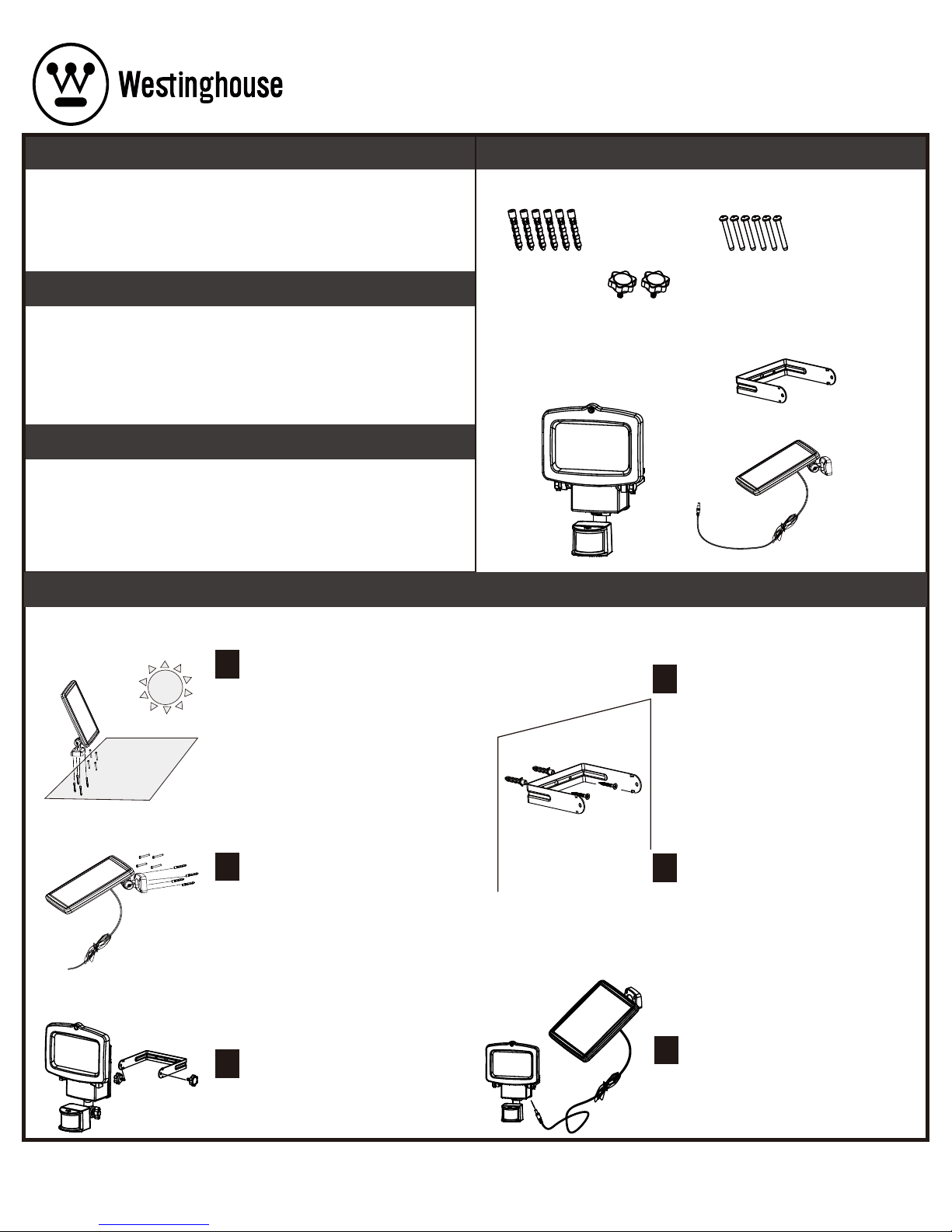
Screws (6)Wall Anchors (6)
Star Knobs (2)
PARTS
A - Light Fixture
B - Solar Panel
C - Mounting Bracket
CAUTIONS: BATTERY INSTRUCTIONS
PRE INSTALLATION
WARNING:
•Do not expose the light to re or intense heat.
•Do not immerse in water.
•Your motion light and solar panel are both weather-resistant.
•Never look directly into the solar motion light when illuminated.
HARDWARE INCLUDED (note: some parts may be pre-assembled)
USE RECHARGEABLE BATTERIES ONLY.
•Always purchase the correct size and grade of battery most suitable for the intended
use.
•Remove batteries from equipment which is not to be used for an extended period of
time.
•Dispose of the battery in accordance with local, state and federal regulations. (Do not
burn or discard the battery in a municipal water system or other body of water.)
CARE AND MAINTENANCE
CARE & MAINTENANCE
•From time to time, ensure the plug between the solar panel and light is securely
connected.
•The solar panel should be cleaned with a damp cotton cloth on a regular basis.
This will ensure optimal performance and battery charging.
•Never let any abrasive material come into contact with the solar panel.
MOUNTING THE LIGHT FIXTURE
ON THE MOUNTING BRACKET
Place the Light Fixture on the Mounting
Bracket and secure the Light Fixture in
place with the Star Knobs.
5
INSTALLING THE MOUNTING
BRACKET
Locate the Mounting Bracket six to eight
feet above ground on a solid surface
capable of supporting the Light Fixture
and secure enough so that it will not move
when exposed to vibrations or wind.The
Light Fixture must be high enough to allow
for motion detection and light distribution.
3
Mark the hole locations of the Mounting
Bracket, then set the Mounting Bracket
aside. Check that the marked areas are
clear of obstacles such as cables and
electrical lines. Drill holes for the enclosed
Screws and Wall Anchors. Insert the Wall
Anchors then secure the Mounting Bracket
in place with the Screws.
4
INSTALLING THE SOLAR PANEL
Ensure your Solar Panel is placed so
that its exposure to the sun is optimized.
Be aware of objects such as trees or
property overhangs that may impede the
panel’s ability to generate a charge. To
adjust the solar panel loosen the wing
nut and position the panel .When desired
position is achieved ,tighten wing nut until
secure.The Solar Panel is equipped with a
9.84 ft. connecting wire, so the Light
Fixture and Solar Panel can be installed
up to 9.84 ft. apart.
1
Mark the hole locations of the Base, then
set the Solar Panel aside. Check that the
marked areas are clear of obstacles such
as cables and electrical lines. Drill holes
for the enclosed Screws and Wall Anchors.
Insert the Wall Anchors then secure the
Solar Panel in place with the Screws.
2
A
INSTALLATION
ITEM: Q75AD1424-06
SAFETY INFORMATION
Read all safety precautions and installation instructions carefully
before installing or servicing this xture. Failure to comply with these instructions
could result in a potentially fatal electric shock and/or property damage.
CONNECTING THE WIRES
Carefully route the Power Cord of the
Solar Panel to the Light Fixture and plug
into the socket located on the Light.
Only use solar panels for power charging.
It is not allowed to access other external
charging equipment.
6
B
C
01/18/2017
1/2 E

For additional help and information regarding installation, contact Customer Service at 1-844-551-0680, 8am-5pm,CST Monday – Friday
customerservice@qx-usa.com
, WESTINGHOUSE, are trademarks of Westinghouse Electric Corporation. Used under license by Sky Rich Star Limited. All Rights Reserved.
REPLACING THE BATTERIES
WARNING:
Do not dispose batteries in municipal waste stream or by fire as batteries may
explode. Do not open, short circuit, or mutilate batteries. Dispose of batteries in accordance
with Local, State, and Federal regulations. Contains no toxic metals. Do not mix old and new
batteries. Do not mix alkaline, standard (Carbon-Zinc), or rechargeable (Nickel Cadmium or
Nickel Hydride) batteries with Lithium batteries.
OPERATION
TROUBLESHOOTING
Before the Solar Sensor Light can operate to its full capacity, the Solar Panel needs to be in sunlight for 8-12 hours to fully charge the battery. Turn the light switch
to the “OFF” position. After charge, turn the light switch to “AUTO” or “ON” position.
•Loosen the wing screw to adjust the motion sensor head toward desired detection area.
The side light heads can be adjusted independently in a variety of ways for optimal lighting
coverage.
•
•Turn the light switch to “AUTO” position, the light will turn on automatically at night when
motion is detected.
•Turn the light switch to “ON” position, the light can be used as a standard light.
NOTE: Avoid aiming the control at:
•Objects that change temperature rapidly to prevent false triggering, such as heating vents
and air conditioners.
•Moving objects such as trees and street trac.
!
PROBLEM
Lights will not come on.
Lights ash on and o.
Lights come on for no
apparent reason.
Lights stay “ON”.
A. Light switch is turned o.
B. Cable connection is loose.
C. Motion sensor head is not aimed correctly.
A. Low battery..
A. Motion sensor maybe sensing moving objects
such as trees, trac, etc.
A. Light switch set to ON.
A. Turn light switch to ON or AUTO.
B. The Solar Panel needs to be in sunlight for 8-12 hours
to fully charge the battery.
C. Re-aim the motion sensor to cover the desired area.
A. With light switch set to “OFF”, allow to charge in full
sunlight for 8-12 hours before further use.
A. Reposition motion sensor.
A. Turn light switch to “AUTO”.
POSSIBLE CAUSE SOLUTION
To set the amount of ON time you want the lights to stay on after the motion is detected,
set the time switch to 30”, 60” or 120”
OPERATION
Use a Phillips head screwdriver to remove the 4 screws holding the battery cover in place.
Gently pull battery pack away from the Light Fixture and disconnect the battery connector.
Replace old battery pack with a new 6V AA Ni-Mh 2000mAh rechargeable battery pack.
Connect the battery connector and insert battery pack into the Light Fixture. Replace the
battery cover by aligning it properly and replacing the 4 screws removed earlier.
ITEM: Q75AD1424-06
ON OFF
AUTO
30” 60” 120”
01/18/2017
2/2 E
B. Heat being reected from other objects may
be turning the motion sensor on and o.
B. Reposition motion sensor.