

Page 1
Installation and Assembly To Wood
Stud or Concrete - Flat Wall Mount
®
with VESA
200, 100, and 75
Model:
MT50 THIN
IMPORTANT! Read entire instruction sheet
before you start installation and assembly.
Parts List
DESCRIPTION QTY. PART #
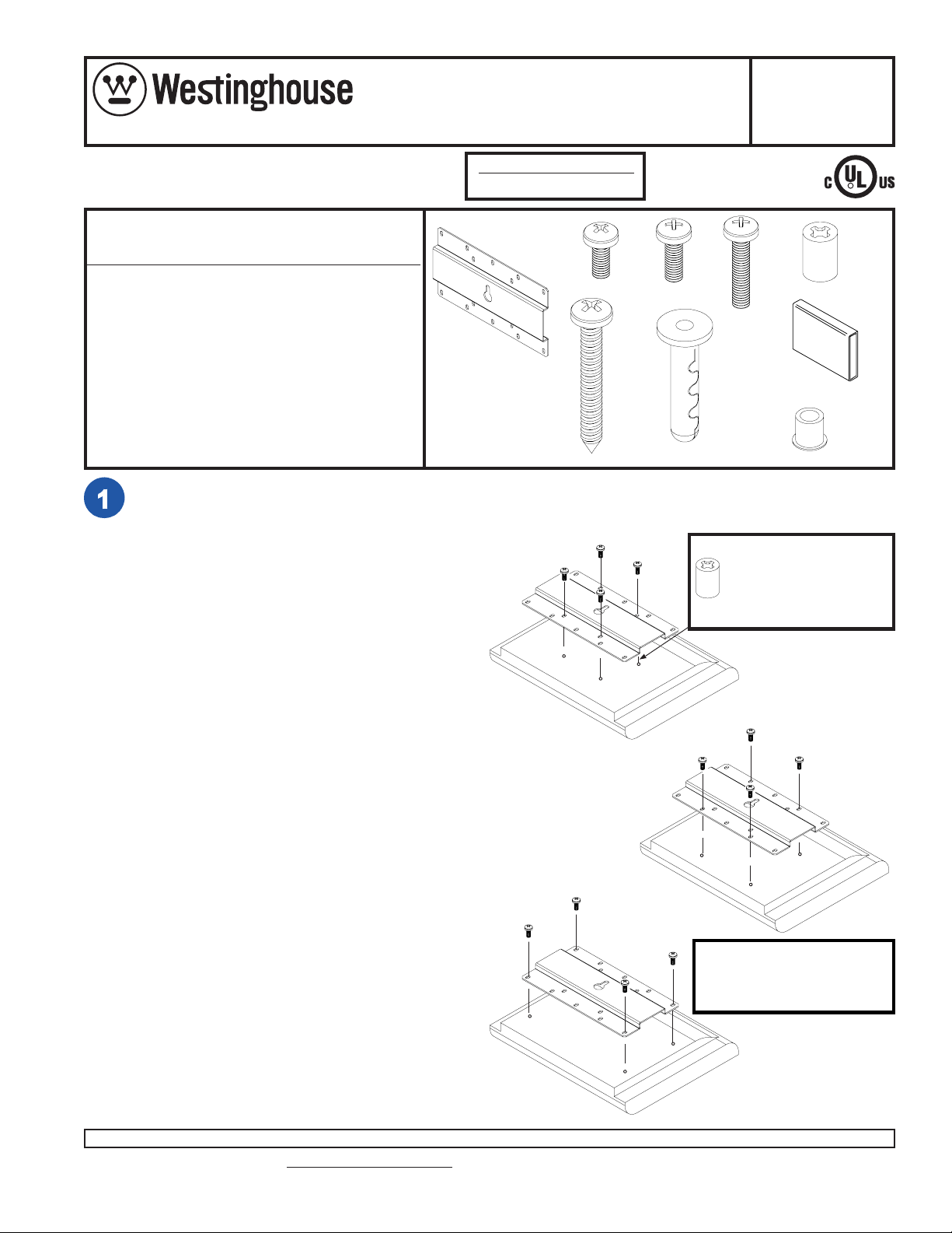
A wall bracket 1 095-4195
B M4 x 10 mm phillips screw 4 520-2027
C M4 x 12 mm phillips screw 4 504-2013
D M4 x 20 mm phillips screw 4 504-2014
E retaining spacer 4 590-5003
F #10 x 1 1/2” wood screw 1 500-2002
G concrete anchor 1 590-0097
H rubber pad 2 590-1159
I screw isolation spacer 1 590-0112
This product is designed to accommodate screens with VESA® compliant hole
pattern. For safe mounting, please make sure that mounting screws turn at least
three complete turns in the screen inserts.
FOR VESA 75 MOUNTING PATTERN: 1) Choose
hole pattern indicated to the right. 2) Attach wall
bracket (A) to back of screen using four 10 mm
screws (B) as indicated. 3) If hole pattern is in a
pocket, attach wall bracket (A) to back of screen
using four 20 mm screws (D) and four retaining
spacers (E) as indicated below.
Max. Load Capacity
50 lb (22.7 kg)
A
A
R
B
C
D
E
H
F
G
I
For screens with a hole
pattern in a pocket,
spacers (E) go between
adapter bracket (A) and
screens.
FOR VESA 100 MOUNTING PATTERN: 1) Choose
hole pattern indicated to the right. 2) Attach wall
bracket (A) to back of screen using four M4 x 10
mm screws (B) as indicated. Note: If you don't get
three complete turns in the screen inserts, use four
M4 x 12 mm screws (C) instead of four M4 x 10 mm
screws (B).
FOR VESA 200 MOUNTING PATTERN: 1) Choose
hole pattern indicated to the right. 2) Attach wall
bracket (A) to back of screen using four M4 x 10 mm
screws (B) as indicated. Note: If you don't get three
complete turns in the screen inserts, use four M4 x
12 mm screws (C) instead of four M4 x 10 mm
screws (B).
Visit the Westinghouse Web Site at www.westinghousedigital.com For customer service call 1-866-287-5555.
A
ISSUED: 05-17-04 SHEET #: 095-9197-2 02-18-051 of 4
A
Note: Screen may appear
slightly different than
illustrated.
Page 2
Installation To Wood Stud Walls
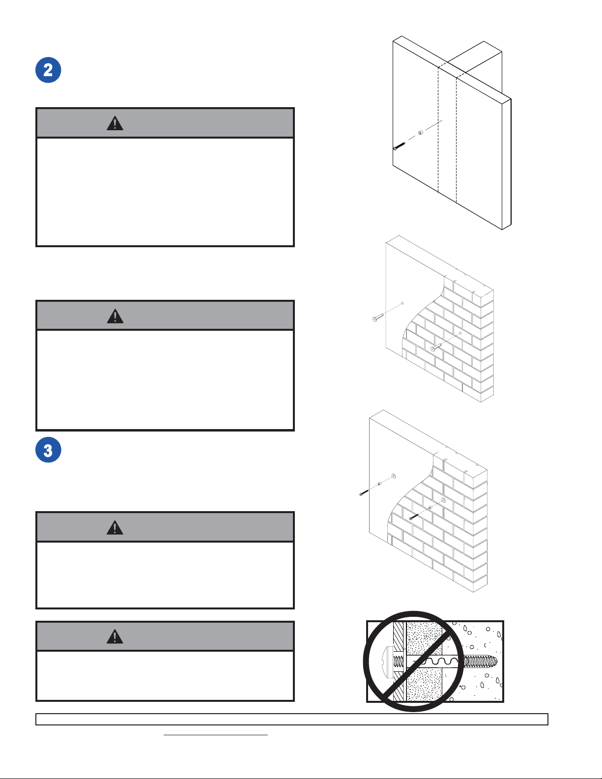
Use a stud finder to locate center of stud. Place screw isolation
spacer (I) over wood screw (F). Screw #10 x 1 1/2” wood screw
(F) into wall. Tighten the screw just until the isolation spacer
contacts the drywall. Be carefull not to overtighten.
WARNING
• Tighten wood screw so that wall plate is firmly attached, but do not overtighten. Overtightening can
damage the screw, greatly reducing it s holding power .
• Never tighten in excess of 80 in • lb (9 N.M.).
• Make sure that mounting screws are anchored into
the center of the stud. The use of an "edge to edge"
stud finder is highly recommended.
Installation to Concrete and
Cinder Block Walls
WARNING
• When installing wall mounts on cinder block, verify that you
have a minimum of 1 5/8" of actual concrete surface in the
1/4" diameter hole to be used for the concrete anchors. It
is suggested that a standard electric drill on slow setting is
used to drill the hole instead of a hammer drill to avoid
breaking out the back of the hole when entering a void or
cavity. Do not drill into mortar joints, which are brittle and
will not provide a stable anchorage!
Drill one 1/4" (6 mm) dia. hole to a minimum depth of 2"
(51 mm). Insert anchor (G) in hole flush with wall as
shown. Place screw isolation spacer (I) over wood
screw (F). Screw #10 x 1 1/2” wood screw (F) into
anchor (G). Tighten screw until the isolation spacer
contacts the wall. Do not overtighten screw.
F
G
I
SOLID
F
SOLID
CONCRETE
CONCRETE
I
CINDER
BLOCK
CINDER
BLOCK
WARNING
• Tighten wood screw firmly, but do not overtighten.
Overtightening can damage the screw, greatly
reducing its holding power .
• Never tighten in excess of 80 in • lb (9 N.M.).
WARNING
• Never use concrete expansion anchor for attachment
of wall plate to concrete walls covered with a layer of
plaster, drywall, or other finishing material.
Visit the Westinghouse Web Site at www.westinghousedigital.com For customer service call 1-866-287-5555.
CUT A WAY VIEW
ISSUED: 05-17-04 SHEET #: 095-9197-2 02-18-052 of 4
Page 3
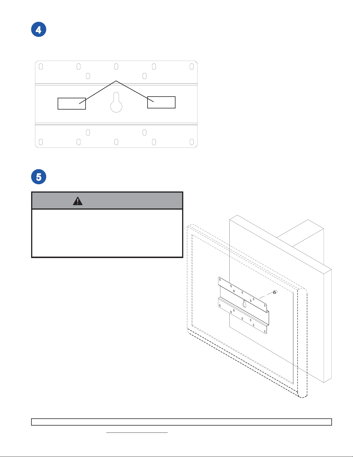
Place rubber pads (H) on back of wall bracket in the center of
the bracket, and adjacent to the top and bottom edges.
H
Use keyhole slot on wall bracket (A) to hang LCD screen on #10 x 1 1/2” wood screw (F).
WARNING
• The screen and bracket may be too heavy and bulky for
one person to handle safely. Two or more persons, or
mechanical lifting equipment, should always be used to
securely attach the screen to the wall bracket. Refer to
your screen’s owner’s manual for additional installation
instructions.
F
A
Note: Refer to your TV owner’s manual for additional instructions which may pertain to the positioning of your
specific TV.
ISSUED: 05-17-04 SHEET #: 095-9197-2 02-18-053 of 4
Visit the Westinghouse Web Site at www.westinghousedigital.com For customer service call 1-866-287-5555.
Page 4

Limited Five-Year Warranty
Westinghouse Digital Electronics warrants to original end-users of this W estinghouse television mounting product (the
“Product”) that the Product will be free from defects in material and workmanship, under normal use, for a period of five
(5) years from the date of purchase by the original end-user, subject to the following terms and conditions:
REP AIR OR REPLACEMENT – For a period of five (5) years from the original date of purchase, W estinghouse Digit al
Electronics will repair any defect in material or workmanship in the Product, or , at its option, replace a defective Product.
Replacement parts and products will be warranted for either the remainder of the original warranty period or ninety (90)
days from the date of delivery to the end-user, whichever occurs last.
OBT AINING WARRANTY SER VICE – To obtain warranty services, you must either personally deliver or ship the Product
to Westinghouse Digital Electronics, freight prepaid. Please call W estinghouse Digital Electronics at (866) 287-5555 to
obtain a Return Merchandise Authorization (“RMA”) and for other instructions regarding return and replacement or
repair of the Product. Westinghouse Digital Electronics will not accept Products delivered to it without an RMA.
EXCLUSIONS TO WARRANTY – This warranty does not cover damage caused by (a) service or repairs by anyone
other than personnel authorized by Westinghouse Digital Electronics, (b) the failure to utilize proper packing when
returning the product, (c) improper installation or the failure to follow Product instructions or warnings, or (d) misuse or
accident, in transit or otherwise.
PROOF OR ORIGINAL PURCHASE – A sales receipt, invoice, or other proof of purchase specifying the original date of
purchase within the five (5) year warranty period must be presented to obtain warranty service. This warranty extends
to the original purchaser and is not transferable.
EITHER REP AIR OR REPLACEMENT IS YOUR EXCLUSIVE REMEDY UNDER THIS WARRANTY. EXCEPT T O THE
EXTENT PROHIBITED BY LAW, WESTINGHOUSE DIGITAL SHALL NOT BE LIABLE FOR ANY INCIDENTAL OR
CONSEQUENTIAL DAMAGES CLAIMED T O ARISE FROM BREACH OF ANY EXPRESS OR IMPLIED WARRANTY
ON THIS PRODUCT. ANY IMPLIED WARRANTY OF MERCHANTABILITY OR FITNESS FOR A PARTICULAR
PURPOSE ON THIS PRODUCT IS LIMITED IN DURATION AND SCOPE TO THE TERMS OF THIS WARRANTY.
Some States do not allow the exclusion or limit ation of incidental or consequential damages, or allow limitations on how
long an implied warranty lasts, so the above limitation may not apply to you. This warranty gives specific legal rights, and
you may also have other rights which vary from S tate to State.
Westinghouse Digital Electronics, LLC
16257 East Gale A ve.
City of Industry , California 91745
Tel: (626) 333-9677.
ISSUED: 05-17-04 SHEET #: 095-9197-2 02-18-054 of 4
Visit the Westinghouse Web Site at www.westinghousedigital.com For customer service call 1-866-287-5555.
and Westinghouse are trademarks of Westinghouse Electric Corporation and are used under license.
 Loading...