

Page 1

IL 33-DAH-1
Digitrip Retrofit System for
Westinghouse DA-75 Breakers
Table of Contents
SAFETY PRECAUTIONS................................................................................................................1
Kit Components List.........................................................................................................................2
Step 1: General Breaker Preparation............................................................................................3
Step 2: Removing the Original Electromechanical Trip Units........................................................3
Step 3: Preparing the Sensors......................................................................................................4
Step 4: Installing the Sensors........................................................................................................4
Step 5: Installing the Trip Unit Mounting Platform..........................................................................5
Step 6: Preparing the Trip Unit Assembly......................................................................................6
Step 7: Installing the Trip Unit........................................................................................................6
Step 8: Installing the Trip Finger....................................................................................................7
Step 9: Installing the Reset Arm Assembly...................................................................................7
Step 10: Installing the DTA Assembly.............................................................................................8
Step 11: Installing the 2-Point Terminal Block.................................................................................9
Step 12: Installing the Breaker Mounted CPT.................................................................................9
Step 13: Final Connection of the Harnesses and Wiring...............................................................11
Step 14: Installing the Auxiliary Switch..........................................................................................14
Step 15: Testing the Breaker.........................................................................................................15
Step 16: Mounting the Cell Harness.............................................................................................15
Step 17: Installing the Retrofitted Breaker in the Cell....................................................................16
Kit Parts List...................................................................................................................................17
Torque Values for General Mounting..............................................................................................21
Torque Values for Copper BUS Connectors...................................................................................21
INDEX............................................................................................................................................25
Page 2

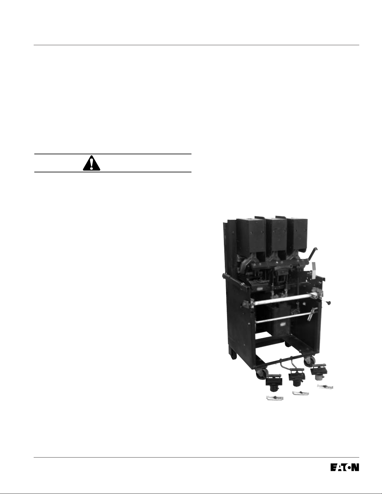
Digitrip Retrofit System for Westinghouse DA-75 Breakers
SAFETY PRECAUTIONS
WARNING
POWER CIRCUIT BREAKERS ARE EQUIPPED
WITH HIGH SPEED, HIGH ENERGY OPERATING
MECHANISMS. THE BREAKERS AND THEIR
ENCLOSURES ARE DESIGNED WITH SEVERAL
BUILT-IN INTERLOCKS AND SAFETY
FEATURES INTENDED TO PROVIDE SAFE AND
PROPER OPERATING SEQUENCES. TO PROVIDE MAXIMUM PROTECTION FOR PERSONNEL ASSOCIATED WITH THE INSTALLATION,
OPERATION, AND MAINTENANCE OF THESE
BREAKERS, THE FOLLOWING PRACTICES
MUST BE FOLLOWED. FAILURE TO FOLLOW
THESE PRACTICES MAY RESULT IN DEATH,
PERSONAL INJURY, OR PROPERTY DAMAGE.
• Only qualified persons, as defined in the National
Electric Code, who are familiar with the installation and maintenance of power circuit breakers
and their associated switchgear assemblies
should perform any work associated with these
breakers.
IL 33-DAH-1
• Completely read and understand all instructions
before attempting any installation, operation,
maintenance, or modification of these breakers.
• Always turn off and lock out the power source
feeding the breaker prior to attempting any
installation, maintenance, or modification of
the breaker. Do not use the circuit breaker as
the sole means for isolating a high voltage
circuit. Follow all lockout and tagging rules
of the National Electric Code and all other
applicable codes, regulations, and work rules.
• Do not work on a closed breaker or a breaker
with the closing springs charged. Trip (open) the
breaker and be sure the stored energy springs
are discharged before performing any work. The
breaker may trip open or the charging springs
may discharge, causing crushing or cutting
injuries.
• For drawout breakers, trip (open), and then
remove the breaker to a well-lit work area before
beginning work.
• Do not perform any maintenance: including
breaker charging, closing, tripping, or any other
function which could cause significant movement
of the breaker while it is on the extension rails.
Doing so may cause the breaker to slip from the
rails and fall, potentially causing severe personal
injury to those in the vicinity.
• Do not leave the breaker in an intermediate
position in the switchgear cell. Always leave it
in the connected, disconnected, or (optional)
test position. Failure to do so could lead to
improper positioning of the breaker and
flashover, causing death, serious personal
injury, and / or property damage.
• Do not defeat any safety interlock. Such
interlocks are intended to protect personnel
and equipment from damage due to flashover
and exposed contacts. Defeating an interlock
could lead to death, severe personal injury,
and / or property damage.
Effective December, 1998
Page 3

Page 2
IL 33-DAH-1
Cutler-Hammer Digitrip Retrofit Kits are available in
a number of configurations that provide a wide
which level of Retrofit Kit is to be installed and
which components are included with the Kit.
range of features. The Digitrip System starts with
the 510 Basic Kit which offers true RMS sensing,
overcurrent protection, and self-testing features.
Advanced Digitrip Retrofit Kits feature zone
interlocking, digital alphanumeric displays, remote
alarm signals, IMPACC communications, energy
The instructions contained in this manual cover the
installation of all levels of Retrofit Kit. If the Kit you
are installing does not contain a certain component,
skip the instructions for that component and
proceed to the next.
monitoring capabilities, power factors, and
harmonic content measurements.
Throughout the Retrofit process, refer to the Torque
Tables at the back of this manual for specific
The following table provides a quick reference of
torque values.
the components supplied with each level of Retrofit
Kit. Before beginning the Retrofit process, take a
minute to review the information contained in the
table. It is important that the Retrofitter understand
If you have any questions concerning the Retrofit
Kit and / or the Retrofit process, contact
Cutler-Hammer at 1-800-937-5487.
510 with
Components 510 Basic Zone 610 810 910
Interlock
Trip Unit
Rating Plug
Auxiliary Current
Transformer
(CT) Module
Auxiliary
CT Harness
Sensors
Sensor Harness
Direct Trip
Actuator (DTA)
Mounting Brackets
and Hardware
External Plug 1 Connector 2 Connector 4 Connector 4 Connector
Harness Harness Harness Harness Harness
Cell Harness
Breaker Mounted
Control Power
Transformer (CPT)
Potential Transf ormer
(PT) Module
Auxiliary Switch
Effective December, 1998
Page 4
IL 33-DAH-1
Page 3
Step 1: General Breaker Preparation
Before attempting to remove the Breaker from
the cell or perform any Retrofit Operation, be sure
to read and understand the Safety Precautions
section of this manual. In addition, be sure to read
and understand the
Instructions for the Application
of Digitrip RMS Retrofit Kits on Power Circuit
Breakers
(Retrofit Application Data - Publication
AD 33-855-1), supplied with the Digitrip Retrofit Kit.
WARNING
DO NOT ATTEMPT TO INSTALL OR PERFORM
MAINTENANCE ON EQUIPMENT WHILE IT IS
ENERGIZED. SEVERE PERSONAL INJURY OR
DEATH CAN RESULT FROM CONTACT WITH
ENERGIZED EQUIPMENT. VERIFY THAT NO
VOLTAGE IS PRESENT BEFORE PROCEEDING.
A. Trip the Breaker and remove it from the Cell.
Move the Breaker to a clean, well-lit work
bench.
To begin the Retrofit Process, refer to the
components list at the end of this manual. Lay
out the components and hardware according
to the steps outlined. The components and
hardware will be used to complete each step
in the Retrofit Process.
Step 2: Removing the Original
Electromechanical T rip Units
Follow the Westinghouse DA-75 Instruction Manual,
originally supplied with the Breaker, to perform the
following procedure.
A. Remove and scrap the original
Electromechanical Trip units and all
associated hardware.
NOTE: It is the responsibility of the
Retrofitter to insure that the Breaker and
all original components are in good
condition. Visually inspect all Breaker
components for signs of damage or wear.
If any signs of damage or wear are
detected for components not included in the
Retrofit Kit, secure the necessary
replacement parts before beginning the
Retrofit Process.
The force necessary to trip the Breaker
should not exceed seven (7) lbs.
Effective December, 1998
Page 5
Page 4
IL 33-DAH-1
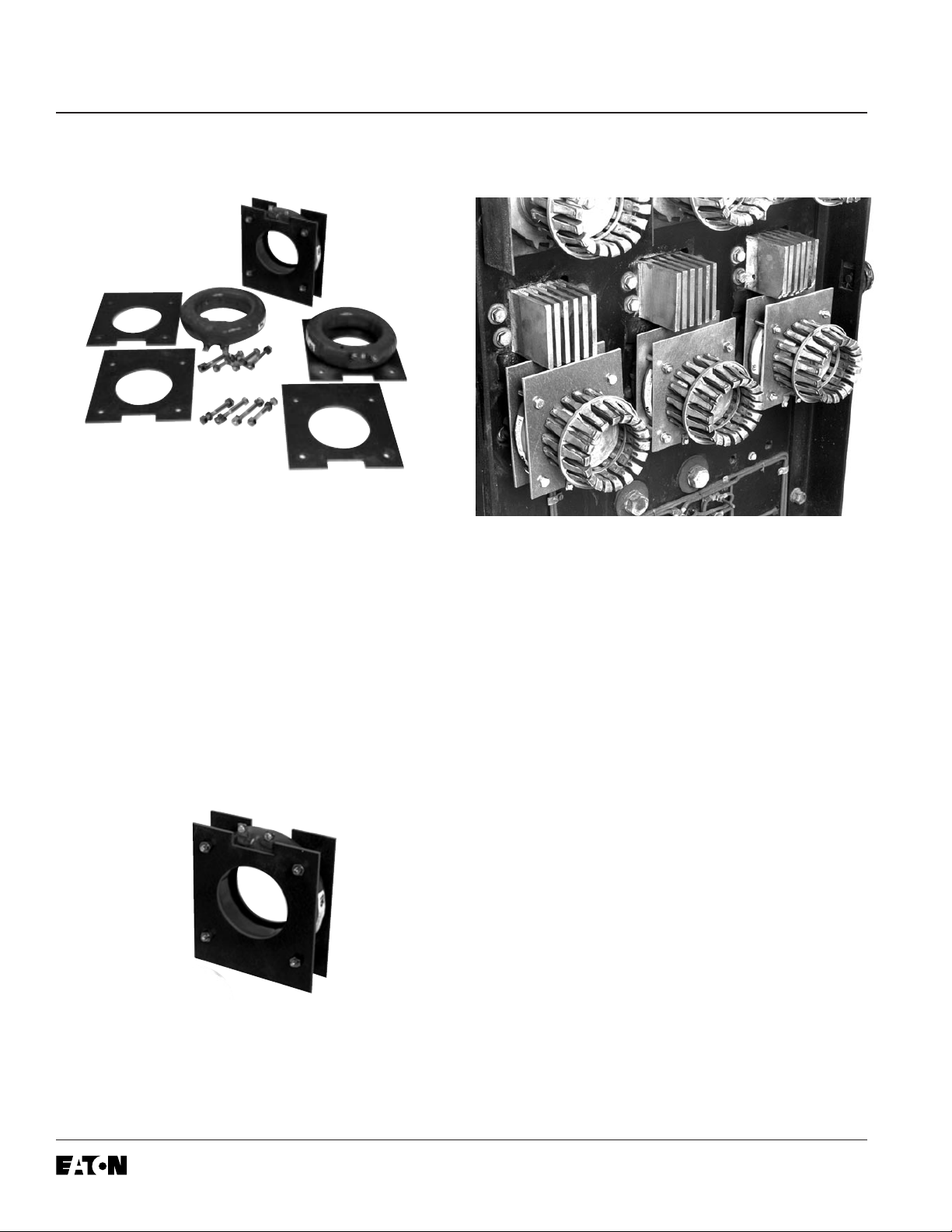
Step 3: Preparing the Sensors
A. Place each Sensor between two Glass Poly
Insulation Plates. The connector stabs should
be positioned towards the cutouts in the
Insulation Plates as shown.
B. Secure the Glass Poly Plates on either side of
the Sensors using the (12) .250-20 × 2.00"
bolts, (24) flat washers, and (12) elastic stop
nuts supplied. Note that the bolts must be
installed so that the bolt heads will be against
the back of the Breaker and the stop nuts away
from the Breaker (same side as the screw
heads of the Sensor terminals). Do not over
tighten the bolts.
Step 4: Installing the Sensors
A. Remove and save the center bolts securing the
bottom Finger Clusters to the Breaker Stabs.
Remove the Finger Clusters.
B. Install a Sensor Assembly over each Breaker
Stab, with the Sensor terminals pointing
downward and the bolt heads outward as
shown.
C. Reinstall the Finger Clusters and secure them
using the original hardware.
Effective December, 1998
Page 6
IL 33-DAH-1
(4)
Page 5
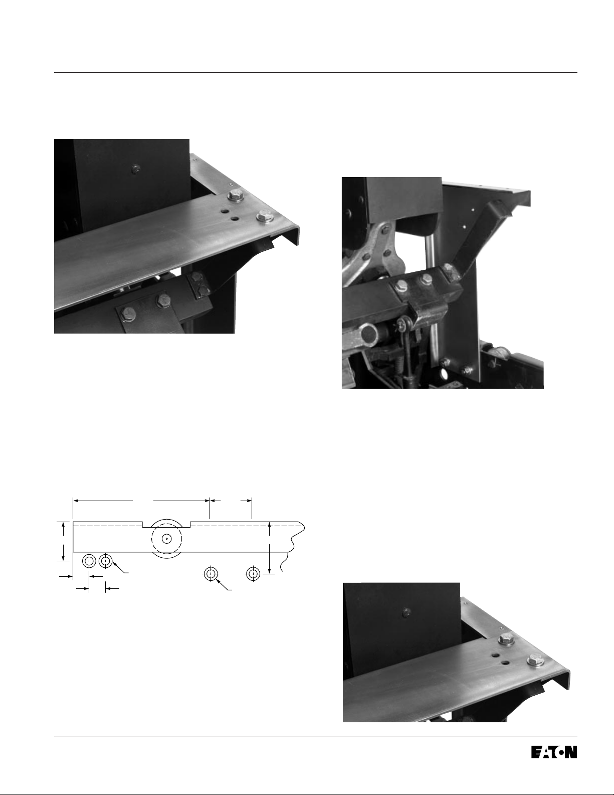
Step 5: Installing the Trip Unit Mounting
Platform
A. Using Drilling Plan “A”, drill and counter sink
two .375" holes in both the left and right
Breaker side plates.
B.
Mount the right and left Trip Unit Support Brackets
to the Breaker side plates as shown, using the
(4) .312-18 × .750" flat head screws, (4) flat
washers, (4) lock washers, and (4) nuts
supplied.
Do not tighten them completely at this time.
NOTE: The holes for mounting the DTA
(see Step 10) should also be drilled and
countersunk in the right Breaker Frame
at this time.
Drilling Plan “A”
6.50" 2.00"
1.81"
Drill 0.375" Dia. and
0.75"
0.75"
Countersink to 0.578"
Head Size (2)
Right Side Only
Drill 0.375" Dia. and
Countersink to 0.578"
Head Size
2.38"
NOTE: For ease of assembly, the 2-Point
Terminal Block (Step 11-A) can be mounted
to the inside of the right Trip Unit Support
Bracket at this time.
C. Mount the Trip Unit Mounting Platform to the
Support Brackets using the (4) .312-18 × .750"
bolts, (8) flat washers, (4) lock washers, and (4)
nuts supplied. Tighten the hardware connecting
the Mounting Platform to the Support Brackets,
and then the Support Brackets to the Breaker
side plates. Assure that the Mounting Platform
and Support Brackets are square with the Breaker.
Effective December, 1998
Page 7
Page 6
IL 33-DAH-1
Step 6: Preparing the Trip Unit Assembly
A.
For Kits Supplied with a PT Module Only.
the PT Module to the Glass Poly Insulation
Barrier as shown, using the (2) .138-32 × .500"
screws, (4) flat washers, (2) lock washers, and
(2) nuts supplied.
D. Mount the Trip Unit Mounting Brackets to the
sides of the Aux. CT Module, using the (4)
.190-32 × .375" screws, (4) lock washers, and
(4) flat washers supplied, so they “pinch” the
Trip Unit in place.
Mount
E. Remove the Trip Unit cover and install the
Rating Plug. Replace the cover.
F. Install the Digitrip Nameplate on the top of the
Trip Unit.
B. Secure the Glass Poly Insulation Barrier to
the back of the Aux. CT Module using the (2)
.190-32 × .375" screws, (2) lock washers, and
(2) flat washers supplied.
C. Install the Trip Unit on the top of the Aux. CT
Module using the (2) brass spacers, (2)
.190-32 × 4.00" screws, (2) lock washers, and
(2) flat washers supplied as shown. Note that
the brass spacers are placed between the
bottom of the Trip Unit and the top of the Aux.
CT Module.
G. Connect the Aux. CT Harness to the Trip Unit
and Aux. CT Module.
Step 7: Installing the Trip Unit
A. Mount the Trip Unit / Aux. CT Module Assembly
to the Trip Unit Mounting Platform as shown,
using the (4) .250-20 × .750" bolts, (8) flat
washers, (4) lock washers, and (4) nuts supplied.
Effective December, 1998
Page 8
IL 33-DAH-1
Page 7
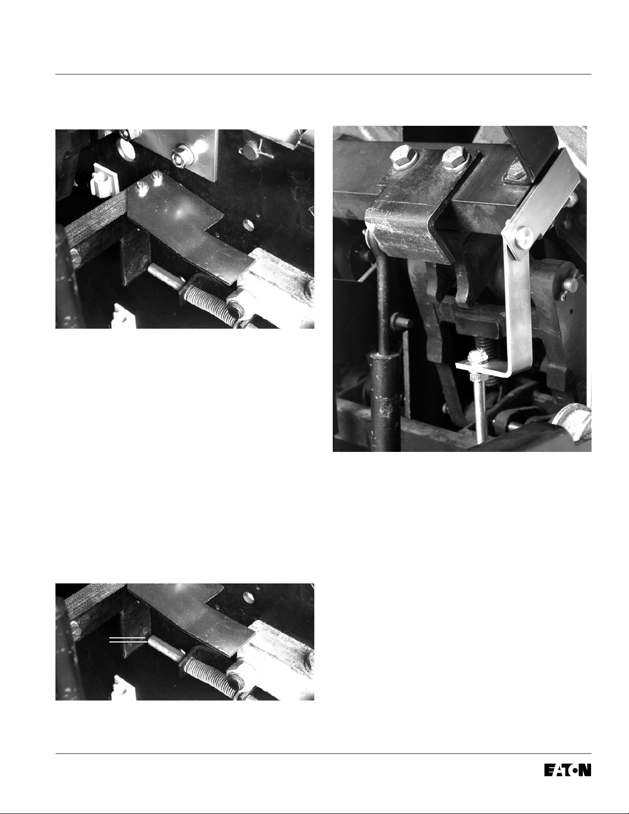
Step 8: Installing the Trip Finger
A. Note the position of the original Trip Finger and
associated “gap” between the Trip Finger and
manual Trip Shaft. Remove the original Trip
Finger and scrap the mounting hardware.
Step 9: Installing the Reset Arm Assembly
B. Mount the new Trip Finger on the top of the
Cross Bar (with the curve upward and the notch
to the right) as shown, and the original Trip
Finger back on the bottom of the Cross Bar.
Secure using the (2) .190-32 × 1.75" bolts,
(4) flat washers, (2) lock washers, and
(2) nuts supplied.
C. Verify that the original Trip Finger has been
reinstalled in its initial position by checking the
gap (noted in Step 8-A) between the original
Trip Finger and manual Trip Shaft.
GAP
A. Remove the original Interlock Arm. Scrap the
original bolts, washers, and nuts.
B. Mount the Reset Arm Assembly to the bottom
of the Cross Bar and the original Interlock Arm
to the top of the Cross Bar in its original
position, using the (2) .190-32 × 1.75" bolts, (4)
flat washers, (2) lock washers, and (2) nuts
supplied. The Reset Arm Assembly should be
positioned so that the Reset Arm is hanging
downward as shown.
Effective December, 1998
Page 9

Page 8
IL 33-DAH-1
Step 10: Installing the DTA Assembly
B. Remove the two nuts, flat washers, and spring
from the Reset Assembly, being careful that the
brass spacer does not slide off the all-thread.
C. Position the DTA Assembly behind the DTA
Mounting Bracket, with the Reset Assembly
Shaft going through the slot in the DTA Reset
Arm. Mount the DTA Assembly to the DTA
Mounting Bracket, as shown, using the (4)
.164-32 × .312" pan / lock screws and (4) flat
washers provided.
D. With the DTA in the latched position and the
DTA Release Arm lifted up over the brass
sleeve, reinstall the large flat washer, spring,
small flat washer, and (1) nut onto the Reset
Assembly Arm. Snug the nut against the brass
sleeve.
®
E. Apply Loc-Tite
242 to the threads at the base
of the installed nut. Install the second nut and
tighten the nuts against each other.
A. Mount the DTA Mounting Bracket to the right
Breaker side panel, as shown, using the holes
drilled in Step 5 A and the (2) .312-18 × .750"
screws, (2) flat washers, (2) lock washers, and
(2) nuts provided.
F. Connect a 24 VDC power supply to the DTA
terminals; positive to positive and negative to
negative. Close the Breaker manually. Energize
the DTA to trip the Breaker; de-energize when
the Breaker trips. Make certain that the DTA
resets. If the Breaker fails to properly trip or
reset, it may be necessary to shorten the brass
spacer on the Reset Assembly Shaft. Make the
necessary adjustments until the trips and resets
are sure and positive each time.
Effective December, 1998
Page 10

IL 33-DAH-1
Page 9
Step 11: Installing the 2-Point Terminal Block
For Kits Supplied with a Breaker Mounted
CPT Only.
Step 12: Installing the Breaker Mounted CPT
A. Mount the 2-Point Terminal Block to the
pre-drilled holes in the right Trip Unit Support
Bracket as shown, using the (2) .138-32 × .750"
screws, (4) flat washers, (2) lock washers, and
(2) nuts supplied.
B. Route the DTA wires from the DTA Assembly to
the 2-Point Terminal Block. After assuring the
wires are clear of any moving components
within the Breaker, connect the DTA wires to
the 2-Point Terminal Block.
A. Align the holes in the Breaker Mounted CPT
with the predrilled holes on the left side of the
Trip Unit Mounting Platform. Secure the CPT to
the Trip Unit Mounting Platform using the (4)
.190-32 × .500" screws, (8) flat washers, (4)
lock washers, and (4) nuts supplied. Note that
the X1 and X2 terminals face the front of the
Breaker.
B. Insert the black plug of the CPT Harness into
the receptacle in the Trip Unit.
Effective December, 1998
Page 11

Page 10
IL 33-DAH-1
C. Route the CPT Harness between the Trip Unit
and the Insulation Barrier to the CPT. Strip .250"
of insulation and attach a .138" ring terminal to
each wire of the CPT Harness. Connect the
CPT Harness wires to the X1 and X2 terminals
of the CPT.
D. Position the fuses on the High Voltage (HV)
Wires in an accessible location. Route the HV
Wires between the Trip Unit and Insulation
Barrier to the Breaker Mounted CPT, then cut
the Load Side of each HV Wire to an
appropriate length. Strip .250" from the Load
Side HV Wires and attach a .138" ring terminal
to each. Attach the HV Wires to the CPT
terminals to achieve the required voltage (see
the following table). The HV Wires will be
connected to the Phase Frames later in the
Retrofit process.
Voltage Required CPT Terminals Used
600 Volt Circuit H1 & H2
E. Attach the Glass Poly Insulation Plate to the top
of the CPT, as shown, using the screws and
lock washers supplied with the CPT kit.
F. Attach the appropriate warning label for the
Breaker to the left of the CPT on the Trip Unit
Mounting Platform.
Voltage Required CPT Terminals Used
480 Volt Circuit H1 & H4
240 Volt Circuit H1 & H3
208 Volt Circuit H1 & H2
Effective December, 1998
Page 12

IL 33-DAH-1
Page 11
Step 13: Final Connection of the
Harnesses and Wiring
A. Feed the Sensor Harness through the hole in
the left side of the Aux. CT Module. Connect the
Sensor Harness to the proper terminals on the
Aux. CT Module. Refer to Section 12 of the
Retrofit Application Data, supplied with the
Retrofit Kit, for detailed wiring specifications.
B. Route the Sensor Harness between the Glass
Poly Insulation Barrier and the back of the Trip
Unit, then down along the right Trip Unit
Mounting Bracket and through the hole in the
Breaker Back Plate as shown. Secure the
Sensor Harness as shown using the wire
clamps and (6) .138-20 × .500" thread cutting
screws supplied.
Connect the green ground wire from the Sensor
Harness (with the ring terminal) to the screw in
the left side of the Aux. CT Module.
C. Route the Sensor Harness to the bottom of the
Sensors. Connect the ring terminals of the
Sensor Harness to the Sensors. Refer to
Section 12 of the Retrofit Application Data,
supplied with the Retrofit Kit, for detailed wiring
specifications.
Depending on the Sensors supplied with the
Retrofit Kit, the following convention applies.
Sensor Style No.
4A35613H01 X1-X2 = 3000 A
Effective December, 1998
Page 13

Page 12
D.
For Kits Supplied with a PT Module Only.
Refer to Section 7-3, Power Flow Convention of
the Retrofit Application Data, supplied with the
Retrofit Kit for additional wiring information and
to verify the Phase Convention used on this
Breaker Application.
Route the PT Wires between the Glass Poly
Insulation Barrier and the back of the Trip Unit,
then down along the right Trip Unit Mounting
Bracket to the area where the original
Electromechanical Trip devices were removed
(Step 2).
The PT Wires are marked for connection to
Phases 1, 2, and 3 with corresponding
numbers.
NOTE: Before cutting the PT Wires, verify
the Phase Convention used on the Breaker
Application.
IL 33-DAH-1
E.
For Kits Supplied with a Breaker Mounted CPT
Only.
Route the
of the Breaker through the opening in the
Breaker Back Plate and along the rear of the
Breaker to the top Phase Frames.
Note: The power convention of the
Westinghouse DA-75 Series Breakers is
normally
Breaker Phase Frames are on the
of the Breaker and the Bottom Breaker
Stabs are on the
The HV Wires from the CPT MUST BE
ATTACHED to the
it is determined that the power flow for the
Breaker application is opposite the normal
convention, the HV Wires must be attached
to the Bottom Phase Frames. The bolts used
to secure the PT Wires can be used to
connect the HV Wires.
Line Side
Top to Bottom
Load Side.
Line Side
HV Wires to the rear
, meaning the Top
Line Side
of the Breaker. If
Route the PT Wires to a position suitable for
attachment to the proper Breaker Phase
Frames. Move the PT Wire markers to a
position where they will still be attached to the
wires after cutting. Cut the wires to length, strip
each wire .250", and install a .250" ring terminal
to each PT Wire.
Connect each PT Wire to the corresponding
Breaker Phase Frames using the (3)
.250-20 × .500" bolts, (3) lock washers, and
(3) flat washers supplied.
Note: The
than necessary and are cut during the
following steps. Before cutting the wires, be
sure that sufficient length is left so that the
connections can be made to the correct
Finger Clusters or Phase Frames.
For Kits Supplied with a Breaker Mounted CPT
F.
Only.
Using a .234" drill, drill and tap one hole in
the top of the Phase 1 and 2 or Phase 2 and 3
Phase Frames.
G.
For Kits Supplied with a Breaker Mounted CPT
Only.
Cut the HV Wires to the appropriate
length for attachment to the appropriate Phase
Frames. Strip .250" from each HV Wire and
attach a .250" ring terminal. Using the (2)
.250-20 × .500" bolts, (2) flat washers, and (2)
lock washers supplied, connect the HV Wires
to the appropriate Phase Frames.
Line Side
HV Wires are longer
Effective December, 1998
Page 14
IL 33-DAH-1
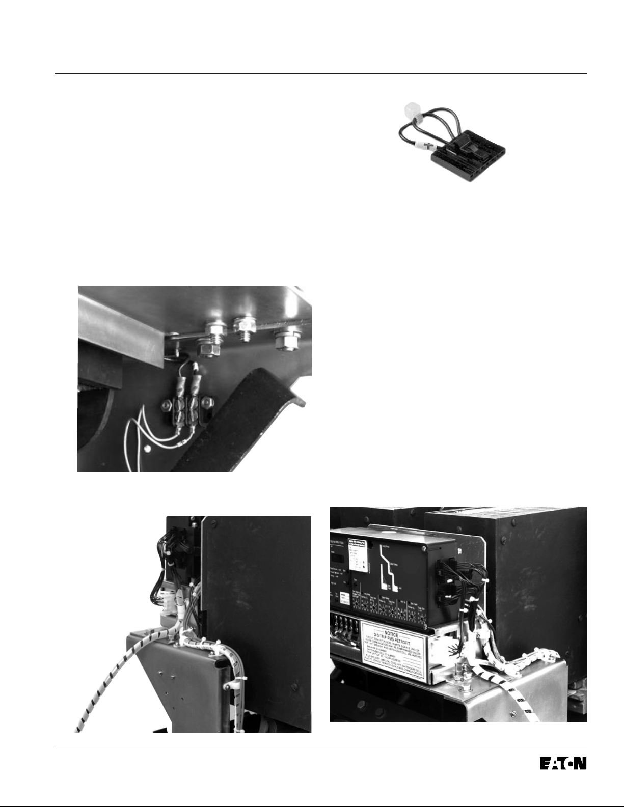
H. Feed the two wires from the DTA Extension
Harness through the opening in the left side of
the Aux. CT Module. Connect the wire marked
“+” to the “OP” terminal and the unmarked wire
to the “ON” terminal.
I. Route the DTA Extension Harness between the
Glass Poly Insulation Barrier and the back of
the Trip Unit, then down along the right Trip Unit
Support Bracket to the 2-Point Terminal Block.
Connect the wire from the DTA Extension
Harness marked with “+” to the “+” terminal and
the unmarked wire to the other terminal.
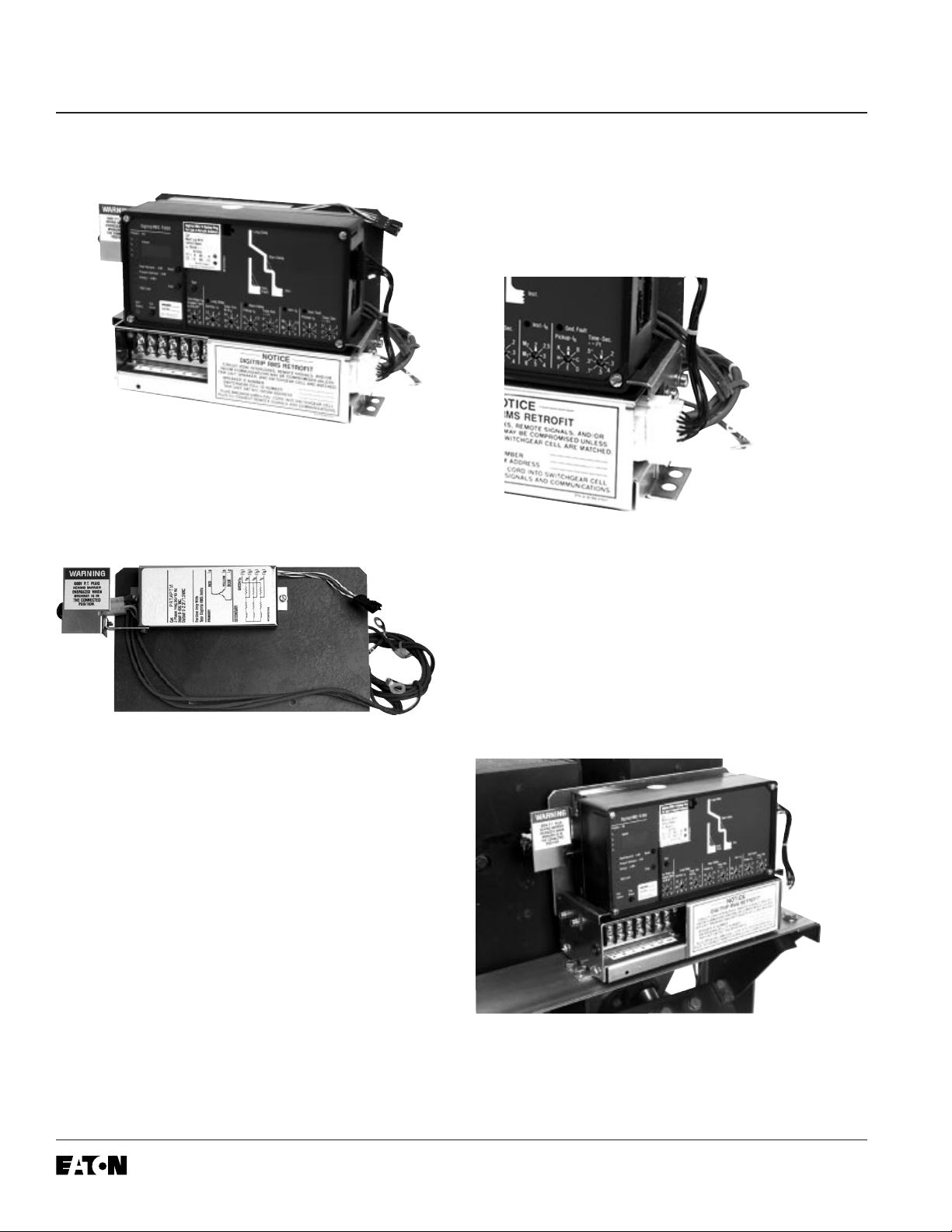
NOTE: For 510 Basic Retrofit Kits, the
External Harness is the plug pictured above.
It is to be plugged into the right side of the
Trip Unit.
For Kits Supplied with a PT Module Only.
K.
Connect the PT Harness to the External
Harness.
L. Use the wire ties, wire clamps, and self
adhesive wire clips provided to dress all wires
and harnesses to keep them away from any
moving parts within the Breaker.
Page 13
J. Connect the External Harness to the Trip Unit.
NOTE: The self adhesive wire clips should
be attached to the right Breaker side panel
to secure the Sensor Harness. The wire
clamps should be attached to the hardware
mounting the Aux. CT Module and the Trip
Unit, as shown, to secure the Sensor
Harness, External Harness, and PT
Extension Harness.
Effective December, 1998
Page 15

Page 14
IL 33-DAH-1
For Kits Supplied with an Aux. Switch Only.
Step 14: Installing the Auxiliary Switch
A. Using diagonals, cut 2.625" off the
Microswitch Arm.
C. Connect the two wires (with ring terminals) from
the External Harness to the Auxiliary Switch.
Connect one wire to the normally “Open”
terminal and the other wire to the “Common”
terminal of the Auxiliary Switch.
D. Making sure the Microswitch arm is behind the
Interlock Bar, mount the Aux. Switch Assembly
to the pre-drilled holes in the right Trip Unit
Mounting Bracket, using the (2) .164-32 × .500"
screws, (4) flat washers, (2) lock washers, and
(2) nuts supplied.
B. Mount the Microswitch to the Auxiliary Switch
Mounting Bracket, as shown, using the (2)
.138-32 × 1.25" screws, (8) flat washers, (4)
lock washers, and (4) nuts supplied.
NOTE: To provide correct spacing, the
hardware must be installed in the following
order. Insert screws with flat washers
installed through the switch. Install flat
washers, lock washers, and tighten the nuts.
Install another set of flat washers, then the
mounting bracket, flat washers, lock
washers, and nuts.
Effective December, 1998
Page 16

IL 33-DAH-1
Page 15
Step 15: Testing the Breaker
A. Measure the force necessary to trip the
Breaker at the point where the DTA impacts the
Trip Finger. The force necessary to trip the
Breaker MUST NOT EXCEED SEVEN (7) lbs.
B. The Retrofit must be tested using primary
injection. Refer to Section 8 of the
Instructions
for the Application of Digitrip RMS Retrofit Kits
on Power Circuit Breakers
(Publication
AD 33-855-1, June, 1997), supplied with the
Retrofit Kit, for detailed testing procedures and
specifications. For test information specific to
the Trip Unit, refer to the IL publication supplied
with the Retrofit Kit (see the Pick List for the
IL number).
C. While Section 8 of the
Instructions for the
Application of Digitrip RMS Retrofit Kits on
Power Circuit Breakers
provides the information
necessary for testing the Breaker, please keep
the following notes in mind when reviewing
other sections of the publication.
CAUTION:
When all testing is complete, the Trip
Unit must be reset. Failure to do so may cause
the battery in the Rating plug to run down.
Notes:
1. Publication AD-33-855 was created
specifically for the “hundred” series (500,
600, 700, etc.) Retrofit Kits. Therefore certain
sections and figures do not apply to the
“ten” series (510, 610, 810, etc.) Retrofit Kits.
Specifically, these are Sections 13 and 14, as
well as Figures 3-2, 3-3, and 3-4.
3.
For 810 and 910 Kits Only.
Without any
power applied to the system (neither the 120
volt power supply nor the Aux. Power
Module connected), plug the External
Harness into the Cell Harness and check the
impedance between COM 1 and COM 2. The
impedance should be between one (1) and
three (3) ohms. If the impedance is not
within this range, trace the wiring and
examine each connection to assure its
integrity.
Confirm that the IMPACC communication
wiring is correct by following the procedures
detailed in Section 7.4 of the Instructions for
the Application of Digitrip RMS Retrofit Kits
on Power Circuit Breakers. Note that for 810
and 910 Kits, the impedance between COM 1
and COM 2 should be between one (1) and
three (3) ohms.
When testing is complete, disconnect the
External Harness from the Cell Harness.
Final External Harness connection will be
performed in Step 16.
For Kits Supplied with a Cell Harness Only.
Step 16: Mounting the Cell Harness
A. The Cell Harness is to be mounted in the
Breaker Cell. The connector end is to be
mounted on the right front side of the Cell, in a
location suitable for connection with the
External Harness. The Terminal Blocks can be
mounted anywhere space is available in the
Cell as long as connection to the External
Harness can be made.
For All Kits Other Than 510 Basic.
2.
If testing
the Breaker with Short Delay or Ground
Fault functions, be sure to either plug in the
Cell Harness Assembly or use the Zone
Interlock Shorting Plug. Failure to do so may
result in shorter than expected trip times.
Effective December, 1998
B. Route the Cell Harness wiring to keep it away
from any moving parts within the Cell Housing.
Page 17

Page 16
IL 33-DAH-1
Step 17: Installing the Retrofitted Breaker
in the Cell
WARNING
Do not leave the Breaker in an intermediate
position in the switchgear cell. Always leave
it in the CONNECTED, DISCONNECTED, or
(Optional) TEST position. Failure to do so could
lead to improper positioning of the Breaker and
flashover, causing death, serious personal
injury, and / or property damage.
WARNING
It is solely the responsibility of the Retrofitter to
make the necessary modifications to the original Racking Mechanism, or to manufacture a
Racking Bar Adapter, to insure safe racking of
the Breaker into the Cell. If the Retrofitter opts
to modify the original Racking Mechanism, the
Racking Bar Receptacle must be removed from
the Racking Mechanism, moved to a location
where the Racking Bar will not contact the DTA
during racking, and welded to the Racking
Mechanism.
NOTE: It is the responsibility of the Retrofitter
to insure proper Breaker / Cell fit. When racking
the Breaker into the Connected position, the
Retrofitter MUST FOLLOW BOTH the
manufacturer’s instructions and the customer’s
safety standards and procedures for racking a
Breaker into the Connected position.
A. With the Breaker in the Open position and the
springs discharged, slowly rack the Breaker into
the Connected position, making sure there is no
interference or binding. The Breaker should rack
smoothly and without mechanical interference
between any Breaker and Cell parts. The
Retrofitter will feel some resistance when the
primary fingers connect onto the stabs of the
Cell. This is normal.
However, if any unusual resistance is detected
that could be abnormal interference between
the Breaker and Cell parts, stop immediately
and move the Breaker out of the Connected
position. Examine what is causing the
interference and correct the situation.
If the Retrofitter opts to manufacture a Racking
Bar Adapter for use with the original Racking
Mechanism configuration, the drawing and
photo below should be used as a basis.
Breaker Racking Pivot
Adapter
Effective December, 1998
Page 18

IL 33-DAH-1
Digitrip Retrofit Kit Installation Components for the Westinghouse DA-75 Breakers
Step Description Style No. Qty. Comment
Step 3 Sensors 3000/5000 4A35613H01 3
Sensor Mounting Parts 4A35618G04 1
Glass Poly Mounting Plates 6
.250 - 20 × 2.00 Lng. Hex Bolt 12
.250 Flat Washer Stl. 24
.250 - 20 Elastic Stop Nut 12
Step 5 Trip Unit Mounting Platform Parts 4A35618G05 1
Trip Unit Support Bracket R. H. 1
Trip Unit Support Bracket L. H. 1
Trip Unit Mounting Platform 1
.312 - 18 × .750 Lng. Screw Flat 4
.312 - 18 × .750 Lng. Hex Bolt 4
.312 Flat Washer Stl. 12
.312 Lock Washer Stl. 8
.312 - 18 Nut Hex Stl. 8
Page 17
Step 6 Trip Unit 1 See Pick List
Rating Plug 1 See Pick List
Aux. CT Module 6502C78G__ 1
Aux. CT Harness 6502C84G01 1
Trip Unit Assembly Parts 4A35618G07 1
Mounting Bracket L. H. 1
Mounting Bracket R. H. 1
Barrier 1
Digitrip Nameplate 1
Spacer Brass 2
.190 - 32 × 4.00 Lng. Screw Fil. 2
.190 - 32 × .375 Lng. Screw Fil. 6
.190 Flat Washer Stl. 8
.190 Lock Washer Stl. 8
PT Module Kit 6502C82G01 1
.138-32 × .500 Lng. Screw 2
.138 Flat Washer 4 Comm. Only
.138 Lock Washer 2
.138-32 Nut Hex Stl. 2
Ring Terminals (.190, .250, .312, .375, .500), 3 Each Size 5
Effective December, 1998
Page 19

Page 18
IL 33-DAH-1
Digitrip Retrofit Kit Installation Components for the Westinghouse DA-75 Breakers (Continued)
Step Description Style No. Qty. Comment
Step 7 Trip Unit Assembly (From Step 6)
Trip Unit Mounting Hardware 4A35618G08 1
.250 - 20 × .750 Lng. Hex Bolt 4
.250 Flat Washer Stl. 8
.250 Lock Washer Stl. 4
.250 - 20 Nut Hex Stl. 4
Step 8 Breaker Trip Finger Parts 4A35618G09 1
Trip Finger 1
.190-32 × 1.75 Lng. Screw Fil. 2
.190 Flat Washer Stl. 4
.190 Lock Washer Stl. 2
.190 - 32 Nut Hex Stl. 2
Step 9 Breaker Reset Parts 4A35618G10 1
Reset Assembly 1
.250 - 20 × 1.75 Lng. Hex Bolt 2
.250 Flat Washer Stl. 4
.250 Lock Washer Stl. 2
.250 - 20 Nut Hex Stl. 2
Step 10 DTA Assembly Parts 4A35618G11 1
High Force Trip Actuator 4A35618G33 1
DTA Mounting Hardware 4A35618G12 1
Mounting Bracket 1
.312 - 18 × .750 Lng. Screw Flat 2
.312 Flat Washer Stl. 2
.312 Lock Washer Stl. 2
.312 - 18 Nut Hex Stl. 2
.164 - 32 × .312 Lng. Screw Pan Lock 4
.164 Flat Washer Stl. 4
Loc-Tite® 242 1
Step 11 Terminal Block Parts 4A35618G13 1
2-Point Terminal Block 1
.138 - 32 × .750 Lng. Screw Fil. 2
.138 Flat Washer Stl. 4
.138 Lock Washer Stl. 2
.138 - 32 Nut Hex Stl. 2
Effective December, 1998
Page 20

IL 33-DAH-1
Digitrip Retrofit Kit Installation Components for the Westinghouse DA-75 Breakers (Continued)
Step Description Style No. Qty. Comment
Step 12 Breaker Mounted CPT Kit 8259A91G05 1 CPT Only
Ring Terminals (.138, .190, .250, .312, .375, .500) 2 Each Size CPT Only
CPT Mounting Parts 4A35618G20 1 CPT Only
Glass Poly Insulation Plate 1
.190-32 × .500 Lng. Screw Fil. 4
.190 Flat Washer Stl. 8
.190 Lock Washer Stl. 4
.190-32 Nut Hex Stl. 4
.250-20 × .500 Lng. Hex Bolt 2
.250 Flat Washer Stl. 2
.250 Lock Washer Stl. 2
Warning Label (208, 240, 480, & 600 Volt - 1 each) 1
Step 13 Sensor Harness 1
Sensor Harness Parts 4A35618G14 1
Wire Clamp Nylon 6
.138 - 20 × .500 Lng. Screw T. C. 6
.138 Flat Washer Stl. 6
.138 Lock Washer Stl. 6
Wire Clip 4
.250 - 20 × .500 Lng. Hex Bolt 3
.250 Flat Washer Stl. 3 Comm. Only
.250 Lock Washer Stl. 3
.250-20 × .500 Lng. Hex Bolt 2
.250 Flat Washer Stl. 2 From Step 12
.250 Lock Washer Stl. 2
DTA Extension Harness 6503C83G01 1
External Harness 6502C83G0__ 1
External Harness Parts 4A35618G15 1
Wire Clamp Nylon 4
Page 19
Effective December, 1998
Page 21

Page 20
IL 33-DAH-1
Wire Tie Nylon 10
Digitrip Retrofit Kit Installation Components for the Westinghouse DA-75 Breakers (Continued)
Step Description Style No. Qty. Comment
Step 14 Aux. Switch Kit 4A35618G02 1
Microswitch 1
Mounting Bracket 1
.164 - 32 × .500 Lng. Screw Fil. 2
.164 Flat Washer Stl. 4
.164 Lock Washer Stl. 2 Comm. Only
.164 - 32 Nut Hex Stl. 2
.138 - 32 × 1.25 Lng. Screw Fil. 2
.138 Flat Washer Stl. 8
.138 Lock Washer Stl. 4
.138 - 32 Nut Hex Stl. 4
Step 15 Cell Harness 6503C57G__ 1 Except 510 Basics
NOTE: Due to the wide vintage of breakers and the multiple functions of the Retrofit components, some excess
hardware may remain when the Retrofit is complete.
Effective December, 1998
Page 22

IL 33-DAH-1
Page 21
Torque Values for General Mounting
Decimal Standard Torque Torque
Size (in) Size (in-lbs) (ft-lbs)
.112 4-40 10 0.8
.138 6-32 18 1.5
.164 8-32 36 3.0
.190 10-32 46 3.8
.250 1/4-20 100 8.3
.312 5/16-18 206 17.2
.375 3/8-16 356 29.7
.438 7/16-14 572 47.7
.500 1/2-13 856 71.3
Torque Values for Copper BUS Connectors
Decimal Standard Torque Torque
Size (in) Size (in-lbs) (ft-lbs)
.250 1/4-20 60 5
.312 5/16-18 144 12
.375 3/8-16 240 20
.500 1/2-13 600 50
Effective December, 1998
Page 23

Page 22
IL 33-DAH-1
B
C
D
A
E
F
G
A. Sensors
B. Trip Unit
C. Aux. CT Module
D. Rating Plug
E. Direct Trip Actuator (DTA)
F. Aux. Switch
CPT Kit not pictured.
I
K
J
H
L
G. PT Module
H. Sensor Harness
I. DTA Extension Harness
J. Aux. CT Harness
K. External Harness
L. Cell Terminal Block Assembly
Effective December, 1998
Page 24

IL 33-DAH-1
Notes:
Page 23
Effective December, 1998
Page 25

Page 24
IL 33-DAH-1
We wish to thank you f or purchasing the Digitrip Retrofit System. Digitrip Retrofit Kits are designed and manufactured in
America with pride. All the components are engineered to fit the e xisting Circuit Break er with little or no modifications to
the existing Breaker. Howe ver due to the wide variety and vintage of Breakers in use today, an occasional problem may
arise. Please contact us with any questions, comments or concerns.
Phone: 1-800-937-5487 Fax. (724) 779-5899
The instructions for installation, testing, maintenance, or repair herein are provided for the use of the
product in general commercial applications and may not be appropriate for use in nuclear applications. Additional
instructions may be available upon specific request to replace, amend, or supplement these instructions to qualify
them for use with the product in safety-related applications in a nuclear facility.
The information, recommendations, descriptions, and safety notations in this document are based on
Cutler-Hammer’s experience and judgement with respect to retrofitting of power breakers. This information should not
be considered to be all inclusive or covering all contingencies. If further information is required, Cutler-Hammer should
be consulted.
NO WARRANTIES, EXPRESSED OR IMPLIED, INCLUDING WARRANTIES OF FITNESS FOR A PARTICULAR
PURPOSE OR MERCHANTABILITY, OR WARRANTIES ARISING FROM COURSE OF DEALING OR USAGE OF
TRADE, ARE MADE REGARDING THE INFORMATION, RECOMMENDATIONS AND DESCRIPTIONS
CONTAINED HEREIN. In no event will Cutler-Hammer be responsible to the user in contract, in tort (including
negligence), strict liability or otherwise, for any special, indirect, incidental, or consequential damage or loss
whatsoever, including but not limited to damage to or loss of use of equipment, plant or power system, cost of capital,
loss of profits or revenues, cost of replacement power, additional expenses in the use of existing power facilities, or
claims against the user by its customers resulting from the use of the information, recommendations, and descriptions
contained herein.
Cutler-Hammer
130 Commonwealth Drive
Warrendale, PA 15086
Effective December, 1998
Printed in U.S.A. - K
Page 26

IL 33-DAH-1
Page 25
INDEX
Symbols
2-Point Terminal Block 9
510 Basic Retrofit Kits 13
A
Auxiliary Switch 14
B
Breaker Mounted CPT 9
C
Cell Harness 15
CPT Terminals 10
D
Drilling Plan “A” 5
DTA Assembly 8
DTA Extension Harness 13
F
Final Connection of the Harnesses and Wiring 11
G
General Breaker Preparation 3
Glass Poly Insulation Plate 10
H
HV Wires 12
K
Kit Components Table 1
M
Mounting the Cell Harness 15
P
Phase Convention 12
PT Wires 12
R
Racking Bar Adapter 16
Removing the Original Electromechanical Trip Units 3
Reset Arm Assembly 7
Retrofit Kit Installation Components 17
Retrofitted Breaker 16
S
SAFETY PRECAUTIONS 1
Sensor Style No. 11
Sensors 4
T
Testing the Breaker 15
Torque Values for Copper BUS Connectors 21
Torque Values for General Mounting 21
Trip Finger 7
Trip Unit Assembly 6
Trip Unit Mounting Platform 5
I
Installing the 2-Point Terminal Block 9
Installing the Auxiliary Switch 14
Installing the Breaker Mounted CPT 9
Installing the DTA Assembly 8
Installing the Reset Arm Assembly 7
Installing the Retrofitted Breaker in the Cell 16
Installing the Sensors 4
Installing the Trip Finger 7
Installing the Trip Unit 6
Installing the Trip Unit Mounting Platform 5
Effective January, 1998
 Loading...