

Page 1
PHOTO
FACT*
Fold
er
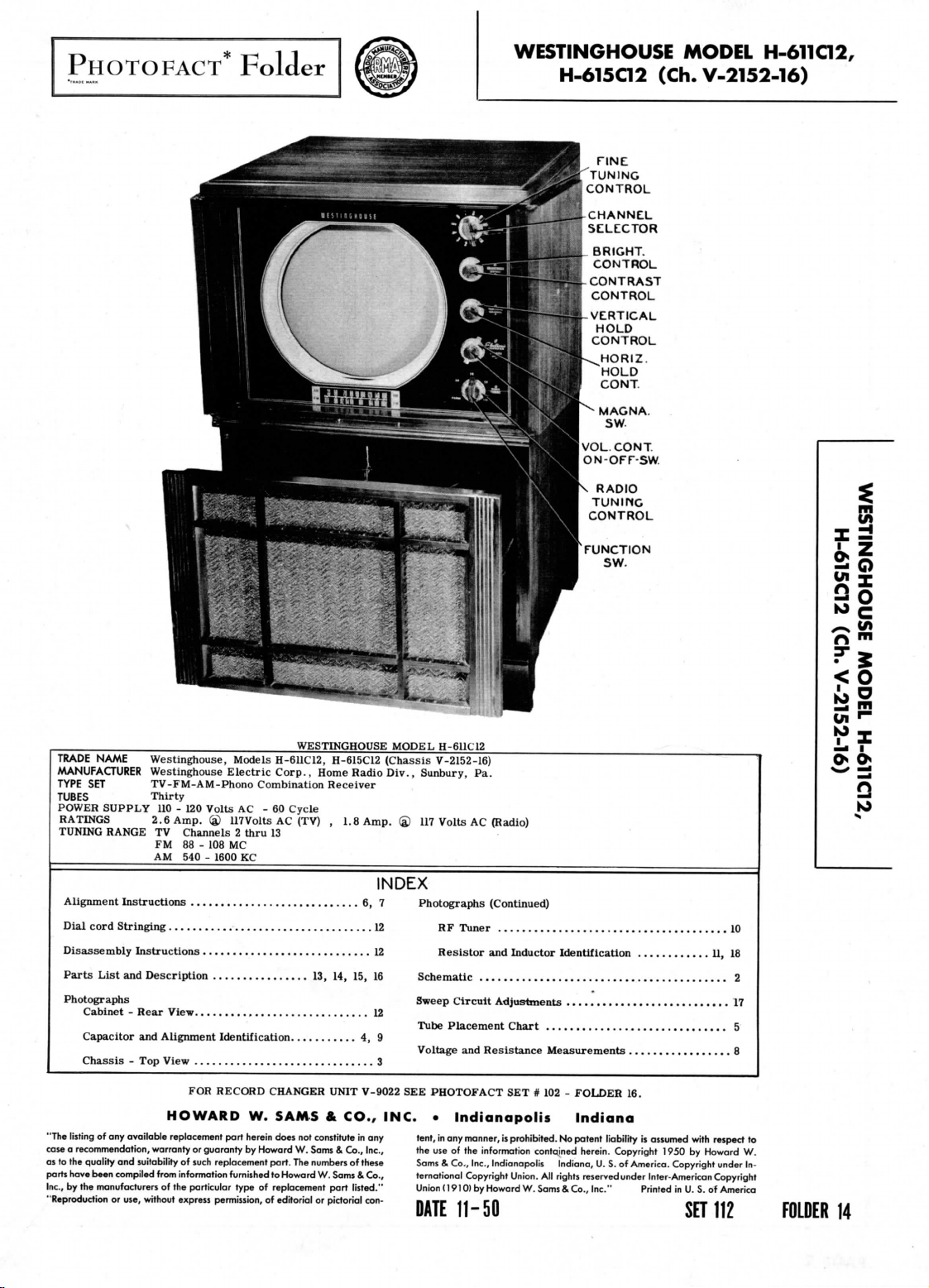
WESTINGHOUSE
H-615C12
TINE
'TUNING
CONTROL
CHANNEL
SELECTOR
BRIGHT.
CONTROL
VERTICAL
HOLD
CONTROL
(Ch.
MODEL
V-2152-16)
H-611C12,
TRADE
NAME
MANUFACTURER
TYPE
TUBES
POWER
RATINGS
TUNING
Alignment
Dial cord Stringing
Disassembly Instructions
Parts
Photographs
"The
listing
case a recommendation, warranty
as
to the
parts
have been
Inc.,
by the
"Reproduction
Westinghouse,
SET
Thirty
Cabinet - Rear
Capacitor
Chassis
quality
Westinghouse Electric
TV-FM-AM-Phono
SUPPLY
List
of any
manufacturers
2.6
RANGE
Instructions
and
and
- Top
available
and
suitability
compiled
or
use, without
110 - 120
Amp.
TV
Channels 2 thru
FM
88 - 108
AM
540 -
12
Description
View
Alignment
View
HOWARD
replacement
from
of the
express
Models
Volts
AC - 60
(a)
llTVolts
MC
1600
KC
6, 7
12
13, 14, 15, 16
12
Identification
3
FOR
RECORD
W.
part
guaranty
replacement
furnished
type
permission,
herein does
by
or
of
such
information
particular
WESTINGHOUSE
H-611C12,
Corp.,
Combination Receiver
AC
13
CHANGER
SAMS & CO.,
Howard
part.
to
of
replacement
of
H-615C12
Home
Cycle
(TV) , 1.8
4, 9
UNIT
not
constitute
W.
Sams & Co.,
The
numbers
Howard
W.
Sams & Co.,
part
editorial
or
pictorial
Radio
of
listed."
MODEL
Sunbury,
® 117
H-6UC12
V-2152-16)
Pa.
Volts
AC
Amp.
(Chassis
Div.,
INDEX
Photographs
Schematic
Sweep
Tube
Voltage
V-9022
SEE
PHOTOFACT
INC. • Indianapolis
in any
Inc.,
these
con-
tent,
the
use of the
Sams & Co., Inc.,
ternational Copyright Union.
Union
DATE
(Continued)
RF
Tuner
Resistor
and
Circuit
Placement Chart
and
Resistance
in
any
manner,
information contained herein. Copyright 1950
(1910)
by
Howard
11-50
(Radio)
Inductor
Adjustments
SET # 102 -
is
prohibited.
Indianapolis
All
W.
Sams & Co.,
....
Identification
Measurements
FOLDER
Indiana
No
patent liability
Indiana,
rights reserved under Inter-American Copyright
..
16.
is
assumed
U. S. of
America. Copyright under
Inc."
Printed
with
by
Howard
in U. S. of
SET
. 11, 18
..8
respect
America
112
10
2
17
5
to
W.
In-
FOLDER
Oi
K>
14
Page 2
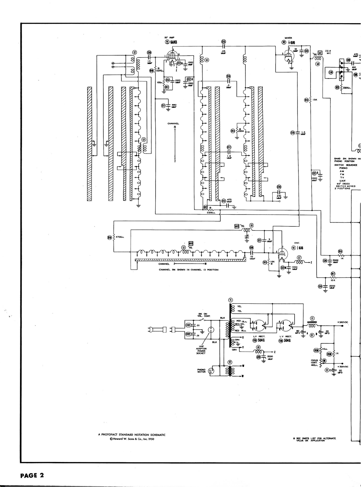
®UK5
PAGE
2
A
PHOTOFACT STANDARD
©Howard
W.
NOTATION
Sami & Co., Inc.
SCHEMATIC
1950
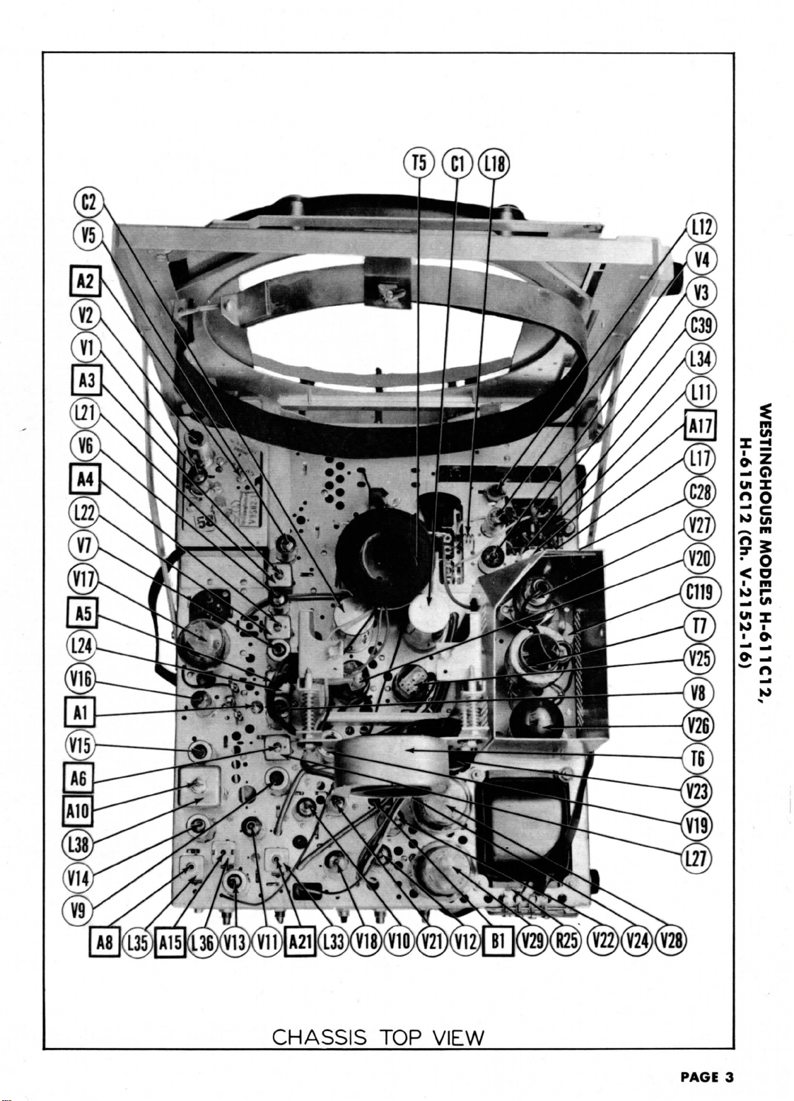
Page 3
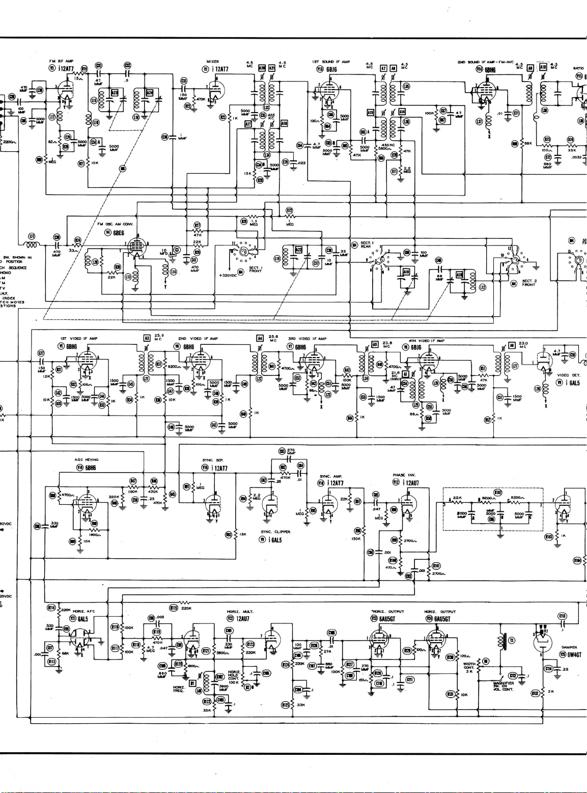
FM
RF AMP
Page 4

WESTINGHOUSE MODEL
H-AT502
(Ch.
V-2152-16)
H-6I1C12,
Page 5
o
2
>
UJ
Q_
COCOCO
<
(J
H-611C12,
V-2152-16)
(Ch.
H-615C12
WESTINGHOUSE MODELS
Page 6
PAGE
4
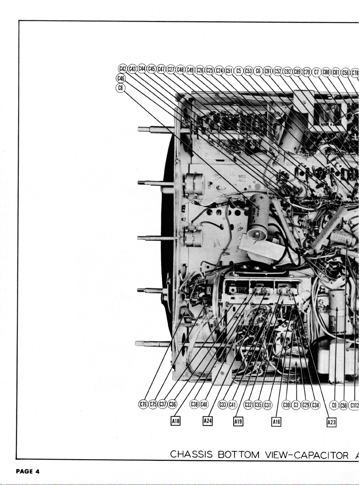
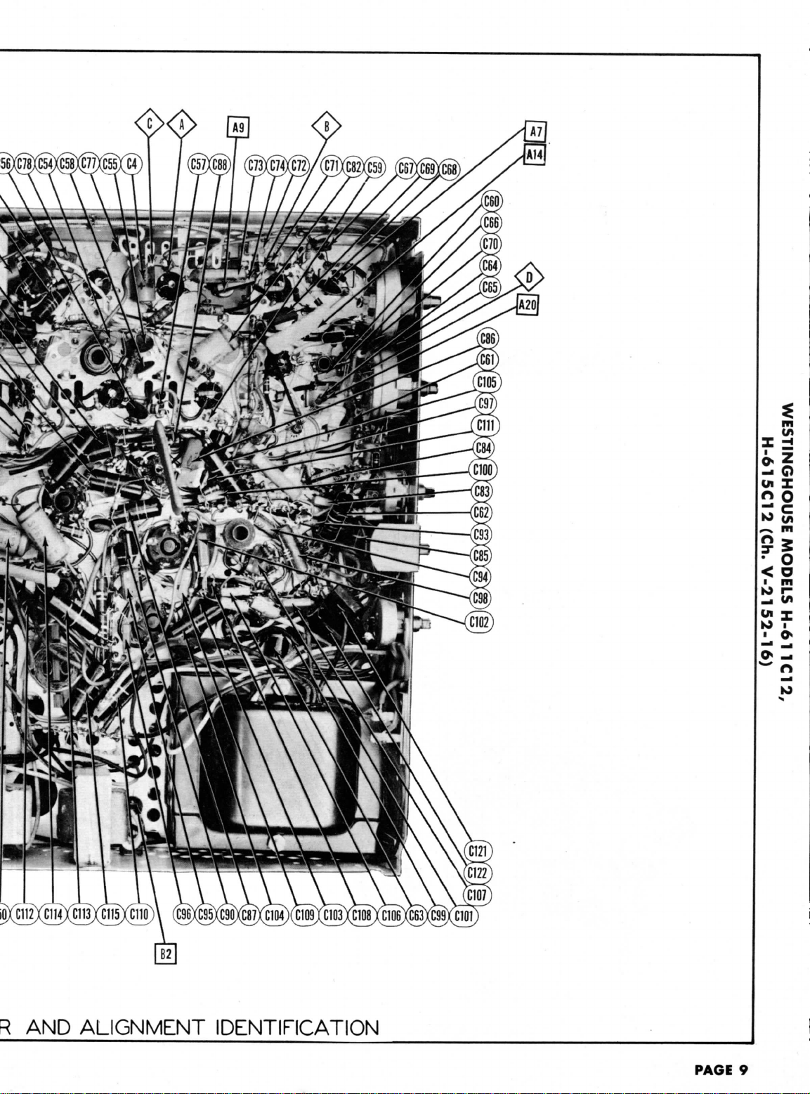
CHASSIS BOTTOM
VIEW-CAPACITOR
X
Page 7
AND
ALIGNMENT IDENTIFICATION
PAGE
9
Page 8

T
B
FM
OSCr
FMRFAMR-
AMCONV
MIXER
I2\DC
(Tj
AMP"
L33
E
REST-
9
L35
CONV
RFAMP.
TOP
VIEW
1STVIDEOIF
^\\
2NDVIDEOIF
VERT
OUTPUT
rhttps://manualmachine.com/
C2 I ( )
v&y
AnSN
v—x
tsAO?)
3RDVIDEOIF
L22 L24 L27
AUDIO
/
I
I
V
OUTPUT.
VI7
\H
6Y6Gy
4THVIDCDIF
Q
SYNC
L25
AM
DET-AVC-
^VK
fe
VERT
AGC
A'ioN
VIDEO
RATIO
HOR.tAPC.
MULT
-
^ING
DET-
CLIPPER
DET
-
^fifif«
SYNC
L33
ISTSOUNDIF
L3s
e
YNCAM'.
VIDEO
L36
-
AGCKEYIN&.
VIDEO
SYNC
OUTPUT.
RATIO
^
4THVIDEOIF
DET-
L27 L24 L22
CLIPPER
Q
DET.
AVC-AFAMP.
[ 9 ) fflHe)
AM
DET- / VI7
3RDVIDEOIF
AUDIO OUTPUT.
V
I63GT/
\
2NDVIDEO
[ e j
(jjBHe)
s'
j
L34
\- FM
|
IF
1ST
[ 6 J
OSC-
IZATT^
MIXER
BOTTOM
VIDEO
IF
AM
e
CONV.
VIEW
L8
e
RF
AMP.
CONV.
TUBE
PLACEMENT
CHART
PAGE
5
Page 9

If
the
picture tube
Turn
the
function
Remove
the
DUMMY
ANTENNA
Direct
Direct
Direct
Direct
Direct
Direct
Connect
Construct a filter
across
the
DUMMY
ANTENNA
Direct
DUMMY
ANTENNA
.
01MFD
.
OlMFD
Use
frequency
DUMMY
ANTENNA
.OlMFD
.
OlMFD
DUMMY
ANTENNA
.
001MFD
Remove
the
Set the
fine
DUMMY
ANTENNA
Two
120SJ
carbon
res.
THE
RF AND
NOT
NORMALLY
switch
converter
GENERATOR
High
side
tube
shield
"dummy"
(V2).
Low
chassis.
the
synchronized
vertical
GENERATOR
High
side
tube
shield
"dummy"
(V2).
Low
chassis.
GENERATOR
High
side
Jack.
Low
chassis.
modulated
GENERATOR
High
side
Jack.
Low
chassis.
GENERATOR
High
side
Jack.
Low
chassis.
dummy
tuning
GENERATOR
Across
als
with
lead.
MIXER
REQUIRE
is to be
to TV
tube
SIGNAL
COUPLING
to
ungrounded
floating
converter
side
"
"
"
for
oscilloscope
input
terminals.
SWEEP
COUPLING
to
ungrounded
floating
converter
side
SIGNAL
COUPLING
to
Video
side
SWEEP
COUPLING
to
Video
side
SIGNAL
COUPLING
to
Video
side
converter
control
SWEEP
COUPLING
antenna
120S1
in
PORTIONS
TV
ALIGNMENT INSTRUCTIONS
removed
to
to
to
signal
to
to
to the
termin-
each
ALIGNMENT
during
position (3rd position clockwise).
(V2)
from
its
GENERATOR
FREQUENCY
21.6MC
(Unmod.
over
tube
22.6MC
25.9MC
25.
23.
23MC
sweep voltage
consisting
GENERATOR
FREQUENCY
25.
over
(10MC
tube
OUND
:
GENERATOR
FREQUENCY
4.
Test
(Unmod.
SOUND
with
60
GENERATOR
FREQUENCY
Test
4.5MC
(450KC
GENERATOR
FREQUENCY
4. 5MC
Test
(Unmod.
tube
and
mid-position
GENERATOR
FREQUENCY
213MC
(10MC
207MC
(10MC SWP)
201MC
(10MC
195MC
(10MC
189MC
(10MC
183MC
(10MC
177MC
(10MC
85MC
(10MC
79MC
(10MC
69MC
(10MC
63MC
(10MC
57MC
(10MC
OF
THIS
ALIGNMENT
INSTRUCTIONS—
alignment,
socket
and
SIGNAL
)
6MC
SMC
from
the
of a
SWEEP
SMC
SWP)
IF
ALIGNMENT USING
SIGNAL
SMC
)
IF
ALIGNMENT USING
ij
modulation
SWEEP
SWP)
SIGNAL
)
replace
the
of its
SWEEP
SWP)
SWP)
SWP)
SWP)
SWP)
SWP)
SWP)
SWP)
SWP)
SWP)
SWP)
RECEIVER
IN THE
FIELD.
the
high
voltage lead
VIDEO
replace
with
CHANNEL
Any
"
OVERALL
VIDEO
signal generator
200Kn
resistor
MARKER
GENERATOR
FREQUENCY
21.6MC
22. 5MC
23.
SMC
25.3MC
26.
IMC
CHANNEL
Any
FM
and
450KC
MARKER
GENERATOR
FREQUENCY
4.
SMC
4.SMC
TRAP
CHANNEL
Any
OSCILLATOR
original
6J6 in its
range.
MARKER
GENERATOR
FREQUENCY
211.
25MC
215.
75MC
205.25MC
209.
75MC
199.25MC
203.
75MC
193.25MC
197.
75MC
187.25MC
191.75MC
181.2SMC
185.75MC
175.25MC
179.75MC
83.25MC
87.75MC
77.
25MC
81.75MC
67.25MC
71.75MC
61.
25MC
65.75MC
55.25MC
59.75MC
HAVE
BEEN
READ
CAREFULLY
should
IF
ALIGNMENT
a 6J6
with
pin 1
CONNECT
VTVM
DC
Probe
to
Test Jack.
to
CHANNEL
AM
DC
Common
DC
Common
DC
detector
showiyui
PoinKjjX
to
Video
Common
chassis.
"
IF
RESPONSE
to the
in
Any
SIGNAL GENERATOR
Probe
Probe
SIGNAL GENERATOR
sweep.
CHANNEL
Any
ADJUSTMENT
Probe
chassis.
ALIGNMENT
CHANNEL
13
12
11
10
9
8
7
6
5
4
3
2
PROPERLY
CHECK
horizontal
series
with
Vert.
Test
Jack.
to
chassis.
CONNECT
VTVM
to
PointX^).
to
chassis.
to
Poinkfc.
to
Pointer!
Use 120 ^ sawtooth voltage
't.
Low
€
ssis.
-t.
Low
€
ssis.
CONNECT
ADIIKT
VTVM ADJUST
thru
All
probe
as
figure
4 to
Low
side
socket.
Vert.
Video
Low
side
ALIGNED
BEFORE ATTEMPTING ALIGNMENT
be
securely taped
removed
ADJUST
Al
A2
A3
A4
AS
A6
input
the
vertical
CONNECT
SCOPE
Amp.
to
Low
ADJUST
A7,
A9
A10
AND
CONNECT
SCOPE
Amp.
to
side
to
Amp.
to
side
to
CONNECT
SCOPE
Amp.
to
Test
Jack.
to
chassis.
and
dressed
to
prevent erroneous indications.
Adjust
for
minimum
Adjust
for
maximum
generator
to
of the
oscilloscope
input
Video
side
AND
VTVM
A8,
OSCILLOSCOPE
Point
Point
AT THE
for
lead
of the
ADJUST
Check
figure
should
necessary,
for
Adjust
for
maximum
Adjust
for
zero reading. A positive
reading
will
setting.
in
scope
ADJUST
A7,
AS,
Disconnect
A9
for
per
A10
Reconnect
place
as per
for
of
Adjust
for
MINIMUM
ADJUST
A12
Adjust
figure
50%
Check
sound
range
a
jiecessary.
A13
Adjust
figure
50%
Check
sound
the
If
be
FACTORY
away
from
the
REMARKS
deflection.
deflection.
maintain a maximum
"
"
horizontal
oscilloscope,
proper
be
for
maximum
figure
maximum
crossover
compromise
tuning
not, a compromise
necessary.
AND ARE
deflection.
and a
for
response curve similar
1. The 22.
obtained
horizontal
4.
figure
5. The
response.
all
marker
of the
to
5. The
of
response.
all low
marker
SMC
be at
40-50%
slightly retouch
response.
REMARKS
deflection.
on
either side
deflection.
stabilizer capacitor
amplitude
2.
capacitor
SMC
at
center
3.
SLIGHTLY retouch
amplitude
lines.
REMARKS
deflection.
to
place
sound
video marker
high
band
can be
fine
tuning
adjustment
place
sound
video marker
band
can be
range
of the
VERY
chassis.
Attenuate signal
-2
volts reading.
500MMF
capacitor
REMARKS
and 26.
IMC
of
response.
A2
thru
and
negative
of the
REMARKS
C4.
and
symmetry
C4.
Adjust
A10 to
of
crossover
and
straightness
REMARKS
marker
as
should
channels
to set
placed well
control.
of A12 may be
marker
as
should
channels
to set
placed well within
fine
tuning
adjustment
STABLE.
THEY
to
markers
If
A6
correct
Adjust
as
lines
A9
shown
in
be at
that
the
within
the
If
not,
shown
in
be at
that
control.
of A13 may
WILL
PAGE
6
Page 10

F
IG.I
FIG.
2
FIG.
3
OSCILLOSCOPE
Volume
insulated alignment
Loop should
DUMMY
ANTENNA
15.
.1MFD
.1MFD
If
FM IF
DUMMY
ANTENNA
.
01MFD
Use
frequency
DUMMY
ANTENNA
.
01MFD
DUMMY
ANTENNA
19.
soon
carbon
res.
"
control
be
High
side
6BE6
(V4).
chassis.
Loop
Alignment
High
side
12AT7
(V3).
chassis.
modulated
High
side
12AT7
(V3).
chassis.
High
side thru
antenna
to
chassis.
should
be at
screwdriver
maintained
SIGNAL
GENERATOR
COUPLING
to pin 7
Low
side
<•
is to be
SIGNAL
GENERATOR
COUPLING
to pin 7 (Grid)
Low
side
signal
SIGNAL
GENERATOR
COUPLING
to pin 7
Low
side
SIGNAL
GENERATOR
COUPLING
300S1
terminal.
"
"IOOMMF
IP
AM
maximum
for
in
same
(Grid)
of
to
performed
of
to
with
(Grid)
of
to
to
#1
Low
side
IOK
^*1-
FIG.4
RADIO
ALIGNMENT
position.
adjusting.
relative
position
SIGNAL
GENERATOR
FREQUENCY
455KC
(4001.
Mod.)
1615KC
1400KC
FM
IF
ALIGNMENT USING
only,
refer
SIGNAL
GENERATOR
FREQUENCY
4. SMC
(Unmod.
)
FM IF
ALIGNMf
60 1 modulation
SIGNAL
GENERATOR
FREQUENCY
4.
SMC
(450KC
SWP)
SIGNAL
GENERATOR
FREQUENCY
108.
SMC
(Unmod.
)
10SMC
OOIMTD
RECEIVER
IOOMMF
<
> IOK
>
<
FIG.5
ALIGNMENT INSTRUCTIONS
INSTRUCTIONS-READ
Output
of
to
chassis
BAND
SWITCH
POS.
AM
(1st
position
clockwise)
"
to
steps
8 and 9 of TV
BAND
SWITCH
POS.
FM
(3rd
position
CW)
NT
USING
and
450KC
BAND
SWITCH
POS.
FM
(3rd
position
CW)
BAND
SWITCH
POS.
FM
(3rd
position
CW)
CAREFULLY
signal
generator should
as
when
RADIO
DIAL
SETTING
Tuning
gang
fully
open
••
Tune
for
max.
AM
SIGNAL GENERATOR
RADIO
DIAL
SETTING
Tuning
gang
fully
open
FM
SIGNAL GENERATOR
sweep.
Use 120
RADIO
DIAL
SETTING
Tuning
gang
fully
open
FM RF
ALIGt*
RADIO
DIAL
SETTING
Tuning
gang
fully
open
Tune
for
max.
deflection
BEFORE ATTEMPTING ALIGNMENT
be no
higher than
receiver
is in
cabinet:
OUTPUT
METER
Across
voice
coil
Sound
IF
DC
Pointful
mon
1*
Vert.
Point^.
side
MENT
DC
Point^S
mon
AND
Alignment.
CONNECT
VTVM
Probe
to
Com-
to
chassis.
AND
OSCILLOSCOPE
sawtooth voltage
CONNECT
SCOPE
Amp.
to
Low
to
chassis.
OUTPUT
METER
Probe
to
Com-
to
chassis.
ADJUST
A14,
A15,
A16,
A17
A18
A19
VTVM
ADJUST
A20,
A21
in
ADJUST
A20,
A21
ADJUST
A22
A23,
A24
necessary
to
Adjust
Fashion
radiate signal into loop
for
maximum output.
output
Adjust
scope
for
horizontal deflection.
Disconnect
for
maximum amplitude
as per
Reconnect
Adjust
Adjust
rocking tuning gang.
obtain
for
while
for
figure
for
for
an
output
reading.
REMARKS
maximum output.
"
loop
of
several
turns
of
of
receiver.
Adjust
tuning
capacitor
and
sound
C4.
for
gang.
symmetry
rocking
REMARKS
maximum deflection.
REMARKS
stabilizer
2 as in TV
capacitor
REMARKS
maximum deflection.
maximum deflection while
Use an
wire
Adjust
maximum
C4.
Adjust
IF
alignment.
and
A
Ul
5
o
(O
(O
3
3 m
Oi
-
0
to
PAGE
7
Page 11

9
Pin
8
Pin
7
Pin
6
Pin
5
Pin
4
Pin
READINGS
3
Pin
RESISTANCE
.in
on
Mej
loon
i3.2Kn
*3.2Kn
on
.en
asn
on
470Kn
t
#2.7
on
on
on
on
4.7Kn
iiooon
18Kn
t23Kn
270Kn
on
.en
on
on
85P.
iiooon
ti7Kn
tisKn
.2n
.in
tiooxn
t48Kn
on
ti.ixn
ti.iKn
ti.iKn
ti.ucn
on
on
on
on
on
on
.jn
.in
.9n
.9n
1.7(1
ii.SKn
i.5Kn
»on
t70Kn
200Kn
t3.7Kn
ononon
.in
.in
.in
s.iKn
IMeu.
t2.8Kn
on
2.2MeK.
i4Kn
on
t47Kn
teKn
.in
on
t400Kn
on
on
on
t68Kn
550Kn
t68Kn
on
.912
.in
on
JW
on
on
an
on
ason
5.5Kn
on
looon
.in
27Kn
470Kn
iisKn
tsoon
t450Kn
tl.SMeg
.in
on
»220Kn
.in
t5Kn
on
tsson
on
looon
an
470n
i.8xn
tiOKn
tiOKn
jsoon
.in
Mee.
2.2
2.2Mee.
ti.iKn
ti.ixn
.in
68Kn
on
68Kn
.in
on
an
320KJJ
t250Kn
on
i.BKn
tsoon
Inf.
Inf.
tsoon
ts.SKn
tsoon
t3.5Kn
on
Inf.
Inf.
ison
ison
tsoon
7ion
TOP CAP
ta.SKn
SKn
.
J3
Inf.
i20oon
Inf.
t3.5Kn
50Kn
on
.in
ien
68Kn
t33Kn
t740n
soKn
Inf.
Inf.
Inf.
Inf.
Inf.
isn
I8n
12
.in
Inf.
Inf.
Inf.
PIN
Inf.
Inf.
isn
18n
PIN U
iooKn
tuon
PIN 10
tuon
Inf.
C5, and C7.
POSITION.
R83, R84,
"NORMAL"
OF
COUNTERCLOCKWISE.
FULLY
SET
CONTROL
FOCUS
V28.
IN
OF
B
SWITCH
JUNCTION
PIN
POSITION.
POSITION.
FROM
FROM
"AM"
IN
IN FM"
EXPANDER
MEASURED
TAKEN
TAKEN
MEASURED
i
PICTURE
t
*
t
MEASUREMENTS
RESISTANCE
AND
VOLTAGE
2
Pin
Pin 1
Tube
Item
9
Pin
8
Pin
7
Pin
6
Pin
5
Pin
4
Pin
READINGS
3
Pin
VOLTAGE
2
Pin
Meg.
u6Kn
loon
1.1
t on
#.en
loon
won
270Kn
A5.7KS2
tiOKn
22Kn
350Kn
350Kn
6AK5
6J6
12AT7
6BE6
6BH6
6BH6
1
V
7VDC
.
100VDC
100VDC
OV.
VAC
3
6.
.7VDC
4
V2
V3
V
V 5V 6V7
VAC
3
6.
OV.
OV.
t
#-.2VDC
OV.
-.4VDC
OV.
f!20VDC
§-5.4VDC
120VDC
-1.5VDC
OV.
6.3VAC
OV.
.9VDC
OV.
75VDC
OV.;OV.
ov.
#115VDC
130VDC
130VDC
t210VDC
I220VDC
340VDC
340VDC
6.3VAC
OV.
OV.
VAC
VAC
3
3
OV.
6.
6.
.7VDC
.7VDC
Men.
2
ean
.9(2
6BJ6
V 8V9
ov.
130VDC
340VDC
ov.
VAC
3
6.
1.1VDC
»i.8Kn
2.
on
.9n
ilOKn
4.7Kn
6AL5
SAH6
6BH6
10
V
VII
-.4VDC
«-20VDC
7.3V0C
»OV.
OV.
300VDC
-125VDC
A
OV.
320VDC
ov.
ov.
ov.
6.3VAC
6.3VAC
6.3VAC
-.8VDC
1-20VDC
OV.
on
IMee.
loon
tuon
IMeg.
12AU7
6BI6
13
V12
V
6.3VAC
6VDC
OV.
ov.
330VDC
175VDC
OV.
270VDC
VAC
3
ov.
6.
11VDC
OV.
OV.
1.4VDC
on
on
Inf.
looKn
Inf.
6BH6
6AL5
14
15
V
V
4.8VDC
ov.
85VDC
OV.
85VDC
OV.
VAC
3
6.
OV.
VAC
3
OV.
6.
-1.2VDC
OV.
IMee.
Meg.
10
teoKn
Inf.
6AV6
6Y6G
12AT7
18
V16
V17
V
OV.
ilEVDC
OV.
VAC
3
95VDC
6.
OV.
4170VDC
OV.
55VDC
120VDC
-.4VDC
»OV.
6.3VAC
VAC
3
il65VDC
6.
6.3VAC
iiesvDC
OV.
ov.
OV.
-.6VDC
OV.
esn
.9n
6BH6
ov.
120VDC
340VDC
OV.
VAC
3
.
6
.6VDC
Meg.
8
39Kn
5Kn
tiooKn
12AU7
V19
6.3VAC
3VDC
20VDC
-22VDC
75VDC
Meg.
on
5
4.
on
on
t
Inf.
Meg.
on
4.8
t38Kn
lOOKn
lOOKn
Inf.
6V6GT
6AL5
12AU7
6AU5GT
6AU5GT
6W4GT
V20
V21
40VDC
6.3VAC
OV.
OV.
OV.
24
V22
V23
V
V25
VAC
3
6.
8.2VDC
185VDC
185VDC
,
VAC
VAC
3
3
7.5VDC
6.
6.
*
110VDC
OV.
OV.
ov.
50Kn
on
on
6Y6G
V26
OV.
6.3VAC
ov.
50Kn
Inf.
Inf.
Inf.
Inf.
5U4G
5U4G
1B3GT
V28
V29
V27
V30
380VDC
380VDC
OV.
OV.
340VAC
340VAC
12
OV.
ov.
ov.
ov.
*
*
-55VDC
45VDC
OV.
350VDC
6.3VAC
OV.
OV.
OV.
OV.
130VDC
3VDC
350VDC
8.2VDC
OV.
18VDC
18VDC
,
320VDC
.9VDC
.3VDC
-3.2VDC
OV.
OV.
OV.
OV.
OV.
OV.
pm
OV.
340VAC
340VAC
.
MEASURE
NOT
DO
*
PINU
350VDC
OV.
PIN 10
380VDC
380VDC
volt-
Mez.
2.2
NOTED.
on
OTHERWISE
12LP4A
UNLESS
POSITION
"TV"
IN
MEASUREMENTS MADE
ALL
6.3VAC
180VDC
POSITION.
350VDC
"NORMAL"
VOLTMETER.
COUNTERCLOCKWISE.
IN
13VDC
to the
for
volts
117
at
maintained
voltage
Line
4.
1,000
20,000
at
are at
measured
Voltage
AC
measurements
volt;
per
Voltoge
ohms
DC
1.
both minimum
given.
minimum.
ore
vary according
set at
controls,
may
service
controls
readings
of the
panels
readings.
age
ohms.
maximum readings
and
setting
Where
Front
5.
6.
com-
direc-
pin to
stated.
clockwise
socket
in a
from
otherwise
socket.
are
counted
of
unless
are
values
bottom
negative
on
numbers
mon
tion
Measured
2. Pin
3.
C5 and C7.
H84,
R83,
OF
1
Pin
-.4VDC
90VDC
230VDC
f§-3.6VD<
Tube
6AK5
6J6
12AT7
1
Item
V2
V
V3
-.2VDC
-.2VDC
II-4VDC
6BE6
V4
0V.
6BH6
6BH6
6BH6
V5
V«
V7
4-75VDC
ov.
6BJ8
8
V
-.4VDC
ov.
6AL5
6BH6
6AH6
10
V9
V
VI 1V12
-.5VDC
-1.2VDC
350VDC
-.2VDC
12AU7
6BJ6
13
V
-.5VDC
6BH6
6AL5
6AV6
17
16
V15
V
V14
V
.4VDC
26VDC
65VDC
OV.
6Y6G
35VDC
3.2VDC
185VDC
3VDC
3VDC
OV.
12AT7
12AU7
6V6GT
6AL5
6AU5GT
6AU5GT
12AU7
1 9
V18
V
V20
V21
V22
6W4GT
V23
V24
V25
OV.
OV.
5U4G
6Y6G
1B3GT
V28
V27
V26
V29
FULLY
OV.
OV.
SET
5U4G
EXPANDER SWITCH
12LP4A
CONTROL
V30
FOCUS
PICTURE
JUNCTION
POSITION.
POSITION.
FROM
"AM"
"FM"
MEASURE.
IN
TAKEN WITH VACUUM TUBE
TAKEN
MEASURED
TAKEN™
§
A
* DO NOT
t
*
Page 12

RF
TUNER-RIGHT
SIDE
PAGE
1O
RF
TUNER-LEFT
SIDE
Page 13

PAGE
18
CHASSIS
BOTTOM
VIEW-RESISTOR
A
Page 14

I
m
o
<
i
m
z
o
0
m
t/>
-I
AND
INDUCTOR IDENTIFICATION
PAGE
11
Page 15

HtlGHT
(MACNA)
DISASSEMBLY
1.
Remove
ten
push-on type control knobs
2.
Disconnect
3.
Disconnect built-in antenna
4.
Remove antenna
5.
Remove pilot light located beneath
6.
Disconnect phonograph jack
7.
Remove wooden block holding
8.
Remove bolt from
9.
"Remove
10.
Remove
11.
Remove
12.
Remove
NOTE:
two hex
four
four
Chassis
speaker
nine
wood
wood
must
terminal
brace
head
wood
be
leads.
bolts
screws
screws
screws
removed
leads.
strip.
from
holding
holding
holding
holding bottom
holding
CABINET-REAR
INSTRUCTIONS
from
front
of
cabinet.
chassis.
chassis.
chassis
in
place.
picture
tube
in
place.
chassis
in
from
screen
speaker
cabinet
cabinet. Remove
to
phono section
plate
to
phono compartment.
in
cabinet.
for
picture tube
of
Remove
removal.
chassis.
cabinet.
speaker.
3
TURNS
VIEW
DIAL
CORD
STRINGING
PAGE
12
Page 16

VI
V2
V3
V4
V5
V6
V7
V8
V9
V10
Vll
V12
V13
V14
V15
V16
V17
V18
TO
V20
V21
V22
V23
V24
V25
V26
V27
V28
V29
V30
ITEM
No.
CIA
C2A
C3
C4
C5
C6
C7
CB
C9
CIO
Cll
C12A
CIS
C14
CIS
C16
C17
C18
C19
C20
C21
C22A
C23
C24
C25
C26
C27
C28
C29
C30
C31
C32
C33
C34A
C35
C36
C37
C38
C39
C40
C41
C42
C43
C44
C45
C46
C47
C48
C49
ITEM
No.
B
C
B
C
D
B
B
B
RF
Amp.
Converter
FM
RF
Mixer
FM
Osc.
Conv.
1st
Video
2nd
Video
3rd
Video
4th
Video
Video Det.
Clipper
AGC
Keying
Video
Output
DC
Rest.
Inv.
1st
Sound
2nd
Sound
AVC
Ratio
Det.
Det.
-AM
Amp.
Audio
Output
Sync.
Sep.
Amp.
Vert.
Mult.
Vert.
Output
Her.
AFC
Hor. Mult.
Hor. Output
Hor. Output
Damper
HVOsc.
HV
Reel.
LV
Reel.
LV
Rect.
Picture
RATING
CAP.
60
20
20
30
30
20
20
10
2
30
20
20
30
150
15
680
1000
1000
470
1000
.25
.5
1.8
470
1.5
10
3
1000
1000
10
5000
5000
5000
150
100
5000
470
47
.5
150
5000
5000
5000
1
10
33
470
68
470
1500
5000
5000
1500
5000
1500
5000
1500
USE
Amp.
-
-AM
IF
IF
IF
IF
-Sync.
-Phase
IF
IF-FM
AVC-AF
-Sync.
Tube
WESTINGHOUSE
VOLT
450
450
450
400
400
400
400
350
50
450
25
25
450
50
PARTS LIST
TUBES
REPLACEMENT
WESTINGHOUSE
PART
No.
6AK5
6J6
12AT7
6BE6
6BH6
6BH6
6BH6
6BJ6
6AL5
6BH6
6BH6
12AU7
6BI6
6BH6
6AL5
6AV6
6Y6G
12AT7
12AU7
6V6GT
6AL5
12AU7
6AU5GT
6AU5GT
6W4GT
6Y6G
1B3GT
5U4G
5U4G
12LP4A
Capacity
values
and
Paper
Capacitors,
PART
No.
V-9575
V-9577
V-9351
V-4880
V-6570
V-3236
V-3236
V-6570
V-9009-1
V-5596
V-5596
V-5596
R5CC21ZY151M
R3CC30SL101M
V-5596
R5CC21ZY471M
R3CC30SL470M
R3CC20SLR50C
R3CC32SL151M
V-9044-1
V-5596
R3CC20SL1ROC
R2CC30CK100D
R3CC30SL330M
R5CC21ZY471M
R3CC30SL680M
R5CC21ZY471M
R5CC26ZY152M
V-5596
V-5596
H5CC26ZY152M
V-5596
H5CC26ZY152M
V-5596
R5CC26ZY152M
AEROVOX
PART
AFH1244J
AFH3666J
PHS350/10
PRS150/4
PRS450/30
PRS25/25
PRS25/25
PRS450/30
PRS50/100
PRS50/50
GP15K
GP680M
BPD-2
GP470M
BPD-001
GP470M
SI1. 5DNPO
CN10FNPO
CN3DNPO
BPD-2
CN10DNPO
BP0-005
BPD-005
BPD-005
GP150M
GP100M
BPD-005
GP470M
GP47M
GP150M
BPD-2
BPD-005
CN10DNPO
GP33M
GP470M
GP68M
GP470M
GP1500M
BPD-006
BPD-005
GP1500M
BPD-005
GP1500M
BPD-005
GP1500M
(SYLVANIA
DATA
STANDARD
REPLACEMENT
6AK5
618
12AT7
6BE6
6BH6
6BH6
6BH6
6BJ6
6AL5
6BH6
6BH6
12AU7
6BJ6
6BH6
6AL5
6AV6
6Y6G
12AT7
12AU7
6V6GT
6AL5
12AU7
6AU5GT
6AU5GT
6W4GT
6Y6G
1B3GT
5U4G
5U4G
12LP4A
given
in the
and in
REPLACEMENT
No.
x 001
x 001
x 005
AND
DESCRIPTIONS
7BD
7BF
9A
7CH
7CM
7CM
7CM
7CM
6BT
7CM
7CM
9A
7CM
7CM
6BT
7BT
7AC
9A
9A
7AC
6BT
9A
6CK
6CK
4CG
7AC
3C
5T
5T
12D
CAPACITORS
rating
column
mmfd.
for
DATA
No.
CORNELLPART
UP6245
'BH2045A
UP32245
BR3045A
BH1235A
BBR2-50
BH3045A
BH202A
BR202A
BH3045A
BRH15015
5W5T15
5W5T1
1D5D5
5W5T5
5W5Q5
5W5T15
1D5D5
1D5D5
1W5D15
105D5
1D5D5
IW5D15
1D5D5
1W5D15
1D5D5
1W5D15
CENTRALAB
PART
D6-150
D6-681
DD-2-102
D6-471
DD-102
TCZ-.5
D6-471
TCZ-1.5
TCZ-10
TCZ-3.3
DD-2-102
TCZ-10
DD-502
DD-502
DD-502
D6-151
D6-101
D6-502
D6-471
D6-470
TCZ-.5
D6-151
DD-2-502
DD-502
TCZ-1
TCZ-10
D6-330
D6-471
D6-680
D6-471
D6-152
DD-502
DD-502
D6-152
DD-502
D6-152
DD-502
D6-152
or
Equivalent)
DMA
BASE
TYPE
are in
Mica
DUBILIER
No.
LD5D5
5R5Q1
5W5Q3
5W5T5
5W5Q7
5W5T5
mfd.
and
Ceramic
ERIE
PART
GP1K-15
GP2K-680
882-2x0015
GP2K-470
811-001
GP2K-470
NPOK-1.
NPOK-10
NPOK-3
882-2 x 0015
NPOK-10
811-005
811-005
811-005
GP2K-150
GP1K-100
811-005
GP2K-470
GP1K-47
GP2K-150
•
882-2
x 005
811-005
NPOK-10
GP1K-33
GP2K-470
GP1K-68
GP2K-470
GP2L-0015
811-005
811-005
GP2L-0015
811-005
GP2L-0015
811-005
GP2L-0015
No.
5
(or
Electrolytic
Capacitors.
SPRAGUE
PART
TVL-3790
TVL-4763
TVA-2722
TVA-1604
TVA-1301
TVA-1711
TVA-1205
TVA-1205
TVA-1711
TVA-1311
29C7
29C4
29C7
29C1
29C1
29C1
1FM-315
1FM-31
29C1
1FM-35
1FM-45
1FM-315
36C2
29C1
MS
MS-43
1FM-35
MS-47
1FM-35
1FM-215
29C1
29C1
1FM-215
29C1
1FM-215
29C1
1FM-215
NOTES
No.
-42
IDENTIFICATION
AND
INSTALLATION
Filter
Filter
Filter
Decoupling
Decoupling
V.
Amp.
Screen
Decoupling
Decoupling
Stabilizing
Cap.
Output Decoupling
Output
Screen
Output
Cathode
Vert.
Output Dec.
Vert.
Output
Cath.
RF
Coupling
AGC
Filter
RF
Suppressor
RF
Decoupling
RF
Decoupling
RF
Cathode
RF
Coupling
RF
Coupling
RF
Coupling
Mixer
Grid
Osc. Coupling
Osc. Grid Cap.
Osc.
RF
Conv.
Fixed
AGC
Fil.
RF
IF
RF
FM
FM
RF
RF
RF
IF
AGC
RF
1st V. IF
AGC
AGC
Filter
Feedback
Bypass
Fil.
Bypass
Trimmer
Filter
Bypass
Bypass
Coupling
Coupling
RF
Cath.
RF
Grid
Filter
Coupling
Coupling
Coupling
FM
RF
De'coup.
AM
Conv.
Decoup.
FM
Mixer
Decoup.
Osc. Coupling
Fixed
Trimmer
Osc. Grid Cap.
Coupling
Osc. Grid Cap.
Osc. Anode
1st V. IF
2nd
2nd
Filter
Bypass
Filter
Filter
V. IF
V. IF
Bypass
Screen
Plate
Screen
Plate
CODES
NOTES
Dec.
Dec.
i
2
"C
h2S
Oi
•"
PAGE
13
Page 17

ITEM
No.
C50
C51
C52
C53
C54
C55
C56
C57
C58
C59
CM
C61
C62
C63
C64
C65A
C66
C67
C68
C69
C70
C71
C72
C73
C74
C75
C76
C77
C78
C79
C80
C81
C82
C83
C84
C85
C86A
C87
C88
C89
C90
C91
C92
C93
C94
C95
C96
C97
C98
C99
C100
CIO!
C102
C103
C104
C105
C106
C107
C108
C109
C110
cm
C112
C113
C114
C115
C116
C117
C118
C119
C120
C121
C122
*
ITEM
No.
R1A
R2A
R3A
R4A
R5A
R6A
R7A
R8
R9
|
f
B
B
C
Items
B
B
C
B
B
B
B
B
Additional
Some
CAP.
.25
5000
5000
1500
47
5000
5000
1500
5000
4.7
33
.25
.022
.1
4.7
5000
5000
5000
47
5000
100
.022
.01
680
.0033
.01
330
.05
.01
150
.1
.022
.005
.25
270
.01
.047
2000
5000
5000
.047
.01
.1
.068
.1
.1
.001
.001
330
330
.001
.005
.047
680
330
3900
.1
.1
.1
100
680
.01
270
.1
.1
.1
.1
.25
.1
.05
.05
270
500
500
.01
.01
C86A,
RESIST-
ANCE
50KO
1500O
500KO
100KO
Shaft
Switch
500KO
2. 5
Shaft
25KO
Shaft
1
Meg.
Shaft
5000O
Shaft
3000O
400(2
models
RATING
RATING
End
Meg.
VOLT
400
500
500
400
400
400
500
500
400
400
400
400
400
400
400
600
400
400
400
400
400
500
WESTINGHOUSE
V-6066-4254M
V-5596
V-5596
H5CC26ZY152M
V-5596
V-5596
R5CC26ZY152M
V-5596
V-5658-6
V-6066-4254M
V-6023-4223K
V-6023-4104M
V-5658-6
V-9044-1
V-5596
RCM20B470K
V-5596
V-6023-4223K
V-6023-4103M
500
RCM20B681M
V-6023-6202M
600
400
V-6023-4103M
V-6023-4103M
500
V-6023-4503M
200
400
V-6023-4103M
500
RCM20B151K
400
V-6023-4104M
400
V-6023-4223K
600
V-6023-4472M
V-6066-4254M
400
500
RCM20B271K
400
V-6023-4103M
V-6023-4503M
400
V-9213
400
V-6023-4503M
V-6023-4103K
V-6023-4104M
V-6023-4683K
V-6023-4104M
V-6023-4104M
V-6023-6102M
600
V-6023-6102M
600
500
RCM20C331J
500
RCM20C331J
600
V-6023-6102M
V-6023-4472M
V-6023-4503M
RCM20B68K
500
500
RCM20C331J
500
HCM30C392K
V-6023-4104M
V-6023-4104M
V-6023-4104M
500
RCM20B101K
RCM20B6B1M
500
V-6023-4103M
RCM20B271K
V-6023-4104M
400
400
V-6023-4104M
400
V-6023-4104M
V-6023-4104M
400
400
V-6066-4254M
400
V-6023-4104M
400
V-6023-4503M
400
V-6023-4503M
500
RCM20B271K
20K
V-5895
V-5895
20K
600
600
C86B, C86C,
WATTS
i
I
i
}
2
>
4
1
i
i
i
4
4
parts
to
use
volume
PART
No.
»
R102A, R102B,
WESTING.
PART
No.
V-9235-2
\
t.
9558-2
t
V-5909
Not
Req.
V-5910
Not
Req.
V-6462
Not
Req.
V-6463
Not
Req.
V-650'0-2
V-5908
be
used
control
AEROVOX
PART
P488-25
BPD-005
BPD-005
GP1500M
BPD-005
BPD-005
GP1500M
BPD-005
GP5K
P488-25
P488-022
P488-1
GP5K
BPD-2
BPD-005
1468-00005
BPD-005
1468-0001
P488-022
P488-01
1468-00075
P688-0033
P488-01
1468-00035
P288-05
P488-01
1468-00015
P488-1
P488-022
P688-005
P488-25
1468-00025
P488-01
P488-047
P688-002
P688-005
W88-005
P488-047
P488-01
P488-1
P488-068
P488-1
P488-1
P688-001
P688-001
1469-00035
1469-00035
P688-001
P688-005
P488-047
1479-0007
1469-00035
1464-004
P488-1
P488-1
P488-1
1468-0001
1479-0007
P488-01
1468-00025
P488-1
P488-1
P488-1
P488-1
P488-25
P488-1
P488-05
P488-05
1468-00025
HV20C
HV20C
P688-01
P688-01
REPLACEMENT
PART
Concentrikit
(
Bll-133
V-9233
Bll-128
E-202
Qll-239
RQ
Oil
-120
RQ
Qll-137
RQ
Qll-114
RQ
with
"Concentrikit".
and
switch
CAPACITORS
REPLACEMENT
CENTRALAB
No.
PART
No.
DD-502
DD-502
D6-152
TCZ-47
DD-502
DD-502
D6-152
DD-502
TCZ-4.7
TCZ-33
DF-203
DF-104
TCZ-4.7
DD-2-502
x 005
DD-502
D6-470
DD-502
D6-101
DF-203
D6-103
D6-681
D6-332
D6-103
D6-331
DF-503
D6-103
D6-151
DF-104
DF-203
D6-502
D6-271
D6-101
DF-503
\0
*
1
DF-503
D6-103
DF-104
DF-104
DF-104
D6-102
D6-102
D6-331
D6-331
D6-102
D6-502
DF-503
D6-681
D6-331
DF-104
DF-104
DF-104
D6-101
D6-681
D6-103
D6-271
DF-104
DF-104
DF-104
DF-104
DF-104
DF-503
DF-503
D6-271
TV2-502
TV2-502
D6-103
D6-103
and
R102C
are
combined into
CONTROLS
DATA
IRC
CLAROSTAT
PART
No.
RTV-56
|
f
1
RTV-57
t
t
AG-84-S
FKS-1/4
AM-40-S
FKS-1/4
AG-61-S
FKS-1/4
AM-19-S
FKS-1/4
RTV-61
RTV-94
assembly Part
CCONT.J
DATA
CORNELL-
DUBILIER
PART
GT4P25
1D5D5
1D5D5
1W5D15
1D5D5
1D5D5
1W5D15
1D5D5
5W5V5
GT4P25
PTE4S2
PTE4P1
5W5V5
1D5D5
1D5D5
1D5D5
5W5Q5
1D5D5
5W5T1
PTE4S2
PTE4S1
5W5T7
PTE6D3
PTE4S1
5W5T3
PTE4S5
PTE4S1
5W5T15
PTE4P1
PTE4S2
PTE6D5
GT4P25
5W5T25
PTE4S1
PTE4S5
PTE6D2
PTE6D5
PTE6D5
PTE4S5
PTE4S1
PTE4P1
PTE4P1
PTE4P1
PTE6D1
PTE6D1
5R5T3
5R5T3
PTE6D1
PTE6D1
PTE4S5
5W5T7
5R5T3
1DR5D4
PTE4P1
PTE4P1
PTE4P1
5W5T1
2R5T7
PTE4S1
5W5T25
PTE4P1
PTE4P1
PTE4P1
PTE4P1
GT4P25
PTE4P1
PTE4S5
PTE4S5
5W5T25
PTE6S1
PTE6S1
No.
No.
V-9607-2.
No.
one
CENTRALAB
PART
No.
SBB-513
SBB-514
AN-83
AK-1
AN-26
AK-1
AN-69
AK-1
AN-10
AK-1
SVP-989
VK-126
ERIE
PART
No.
811-005
811-005
GP2L-0015
NPOM-47
811-005
811-005
GP2L-0015
811-005
GP1K-5
NPOL-33
NPOK-4.7
882-2
x 005
811-005
GP1K-47
811-005
GP1K-100
811-01
GP2K-680
GP2M-0033
811-01
GP2K-330
811-01
GP2K-150
811-005
GP2K-270
811-01
GP2M-002
811-005
811-005
811-01
GP2L-001
GP2L-001
GP2K-330
GP2K-330
GP2L-001
811-005
GP2K-680
GP2K-330
GP1K-100
GP2K-680
811-01
GP2K-270
GP2K-270
811-01
unit
obtainable
SPRAGUE
PART
No.
TC-2
29C1
29C1
1FM-215
29C1
29C1
1FM-215
29C1
MS-55
TC-2
TM-12
TM-1
MS-55
36C2
29C1
1FM-45
29C1
1FM-31
TM-12
TM-11
MS-37
TM-23
TM-11
1FM-335
TM-15
TM-11
1FM-315
TM-1
TM-12
TM-25
TC-2
1FM-325
TM-11
TM-15
TM-22
TM-25
TM-25
TM-15
TM-11
TM-1
TM-1
TM-1
TM-21
TM-21
1FM-335
1FM-335
TM-21
TM-25
TM-15
MS-37
MS-33
MS-24
TM-1
TM-1
TM-1
1FM-31
MS-37
TM-11
1FM-325
TM-1
TM-1
TM-1
TM-1
TC-2
TM-1
TM-15
TM-15
1FM-325
TM-11
TM-11
under
INSTALLATION
Brightness
Contrast
control-rear
Vert,
hold
Horiz.
hold
Attach
per
instr.
Magnifier
switch-front
Volume
control
Magnifier
height
Attach
to R4A per
Magnifier
vert,
Attach
to R5A per
Height
control
Attach
to R6A per
Vert,
linearity
Attach
to R7A per
Width
control-Wire
Focus
control-Wire
IDENTIFICATION
INSTALLATION
AGC
Filter
3rd
V. IF
3rd V. IF
3rd
V. IF
Fixed
4th
V. IF
4th
V. IF
4th
V. IF
4th
V. IF
V.
Diode
Fixed
Video Coupling
Video Coupling
DC
Res. Cath. Byp.
S. IF
1st S.
1st S. IF
1st
S. IF
2nd
S. IF
AVC
Filter
Diode
AVC
Filter
2nd
S. IF
Diode Load Cap.
De-emphasis
Audio
Tone
Tone Compensation
Audio
AF
Amp.
AF
Amp. Dec.
Audio Coupling
Output
Sync. Coupling
Sync.
Sync. Coupling
Sync.
Integrator Net.
Integrator
Integrator
Vert.
Vert.
Vert.
Vert.
Vert.
Decoupling
Hor. Sync. Coupling
Hor.
Hor. Feedback
Hor.
Voltage Divider
AFC
AFC
Hor.
Hor.
MV
Fixed
Hor. MVDec.
Hor. MVDec.
Hor.
Hor.
Hor.
Hor.
Sweep
Hor. Grid
Hor. Output Cath.
Hor. Output
Hor. Output
Hor. Sweep Coupling
Damper
Decoupling
HV
Osc.
HV
Osc.
HV
Osc.
HV
Filter
HV
Filter
Line
Line
Mfgr's
Part
NOTES
control-front
control-front
control-rear
in
"Concentrikit".
and
switch-rear
control
instructions
linearity
instructions
instructions
control
instructions
Wound
Wound
CODES
AND
NOTES
Screen
Cath.
Dec.
Trimmer
Cath.
Screen
Decoup.
Fil.
Filter
Trimmer
Coupling
IF
Plate
Dec.
Screen
Cath.
Grid
Filter
RF
Filter
Dec.
Coupling
Compensation
Coupling
Plate
Byp.
Plate
Coupling
Coupling
Net.
Net.
MV
Cath.
MV
Feedback
MV
Grid
Disch.
Sweep Coup.
Sync. Coupling
Feedback
Filter
Filter
MV
Cath.
Feedback
Trimmer
MV
Grid
MV
Plate
Byp.
Discharge
Coupling
Bypass
Screen
Plate
Filter
Plate
Dec.
Screen
Grid
Filter
Filter
No,
V-9213-1.
control
Dec.
PARTS
ITEM
No.
RIO
Rll
R12
R13
R14
R15
R16
R17
R18
R19
R20
R21
R22
R23
R24
R25
R26
H27
R28
R29
R30
R31
R32
R33
R34
R35
R36
R37
R38
R39
R40
R41
R42
R43
R44
R45
R46
H47
R48
R49
R50
R51
R52
R53
R54
R55
R56
R57
R58
R59
H60
R61
R62
R63
R64
R65
R66
R67
R68
R69
H70
H71
R72
R73
R74
H75
H76
H77
R78
R79
R80
R81
R82
R83
R84
R85
R86
R87
R88
R89
R90
R91
R92
R93
R94
H95
R96
R97
R98
R99
R100
R101
H102
B
C
R103
R104
H105
R106
R107
R108
R109
R110
Rill
H112
R113
RATING
RESISTANCE
22000
1000
20%
22000
220KO
20%
15KO
20%
18KO
20%
47000
10KO
20%
10000
20%
ISO
20%
82S2
10KO
470KSJ
20%
100
OS1
330
2200O
22KO
47KO
15KO
1.5
Meg.
22KO
12KO
1000
looon
20%
10000
20%
10KO
20%
IOKO
20%
82000
1000
10000
20%
oooo
20%
47000
68O
OOKO
oooo
20%
470KO
470KO
OOKO
20%
220KO
47000
68SJ
47KO
10000
20%
4700O
22KO
20%
68KO
22KO
36000
5%
47KO
IMeg.
2.2
Meg.
47KO
6800O
47KO
1000
47KO
56000
100KO
68KO
IMeg.
47KO
2.2
Meg.
1
Meg.
IOCS!
33KO
6800!!
5%
68000
5%
4700O
10
Meg.
470KO
150KO
1
Meg.
33020%
220KO
180O
3900O
470O
1670O
4700O
10KO
18000
5%
1
Meg.
470KO
15KO
2. 2
Meg.
1
Meg.
150KO
22KO
IMeg.
27000
470O
27000
22KO
82000
8200O
10000
100KO
470KO
390KO
4700O
47KO
2.2
Meg.
4700
470O
6800
68KO
20%
20%
LIST
WATTS
~
J
I
f
I
¥
|
1
a
2
i
1
\
2
1
1
a
I
1
I
i
i
I
|
i
i
%
I
I
S
1
1
1
±
i
f
[
z
^
1
i
|
|
1
i
1
i
i
2
I
f
I
4
f
\
1
£
1
i
1
|
1
^
i
I
I
k
i
z
1
2
i
1
i
2
i
2
i
4
10
2
2
i
i
|
i
^
2
I
i
4
f
1
T
I
2
1
s
i
i
i
i
|
1
^
1
10
1
AND
REPLACEMENT
WESTINGHOUSE
PART
No.
HC20AE222K
RC20AE101M
HC20AE222K
RC20AE224M
RC20AE153M
RC20AE183M
RC20AE472K
RC20AE103M
RC20AE102M
RC20AE150M
RC20AE820K
RC40AE103K
RC20AE474M
RC20AE102K
RC20AE330K
RC20AE222K
RC40AE223K
RC30AE473K
RC20AE103K
RC20AE155M
RC20AE223K
RC20AE123K
RC20AE101K
RC20AE102M
RC20AE102M
RC20AE103M
RC20AE103M
RC20AE822K
RC20AE101K
RC20AE102M
RC20AE102M
RC20AE472K
RC20AE680K
HC30AE104K
HC20AE102M
RC20AE474K
RC20AE474K
RC20AE104M
RC20AE224K
RC20AE472K
HC20AE680K
RC30AE473K
RC20AE102M
RC20AE472K
RC20AE223M
RC30AE683K
RC20AE223K
RC30AE362J
RC20AE473K
RC20AE105K
RC20AE225K
RC20AE473K
RC20AE682K
RC20AE473K
RC20AE101K
RC30AE473K
RC30AE562K
RC20AE104K
RC30AE683K
RC20AE105K
RC20AE473K
RC20AE225K
RC20AE105K
RC20AE101K
RC20AE333K
RC20AE682I
RC20AE682J
RC20AE472K
RC20AE106M
RC20AE474K
RC20AE154K
RC20AE105K
RC20AE330M
RC20AE224K
RC40AE181K
RC20AE392K
V-6067-6
V-9085-4
RC20AE472K
RC40AE103K
RC20AE182J
RC20AE105K
RC20AE474K
RC20AE153K
RC20AE225K
RC20AE105K
RC20AE154K
RC20AE223K
RC20AE105K
RC20AE272K
RC20AE471K
RC20AE272K
lt
1
RC20AE102K
RC20AE104K
RC20AE474K
HC20AE394K
RC20AE472K
RC20AE473K
RC20AE225K.
RC30AE471K
RC30AE471K
V-9085-5
RC20AE683K
DESCR
RESI
DATA
IRC
PART
No.
BTS-2200
BTS-2200
BTS-4700
BTS-10K
BTS-1000
BT-2-10K
BTS-470K
BTS-1000
BTS-2200
BTS-22K
BTA-47K
BTS-15K
BTS-1. 5 Meg.
BTS-22K
BTS-12K
BTS-1000
BTS-1000
BTS-10K
BTS-10K
BTS-1000
BTS-1000
BTS-4700
BTS-1000
BTS-470K
8TS-470K
BTS-100K
BTA-220K
BTS-4700
BTS-1000
BTS-4700
BTS-22K
BTA-68K
BTS-22K
BTS-47K
BTS-1 Meg.
BTS-2.2
Meg.
BTS-47K
BTS-6800
BTS-47K
BTA-47K
BTA-5600
BTS-100K
BTA-68K
BTS-1 Meg.
BTS-47K
BTS-2.2
Meg.
BTS-1 Meg.
BTS-33K
BTS-6800-5%
BTS-6800-5%
BTS-4700
BTS-10
Meg.
BTS-470K
BTS-150K
BTS-1 Meg.
BW4-33
BTS-220K
BW-2-180
BTS-3900
BTS-4700
BT-2-10K
BTS-1800-5%
BTS-1 Meg.
BTS-470K
BTS-15K
BTS-2.2
Meg
BTS-1 Meg.
BTS-150K
BTS-22K
BTS-1 Meg.
BTS-2700
BTS-470
BTS-2700
BTS-1000
BTS-100K
BTS-470K
BTS-390K
BTS-4700
BTS-47K
BTS-2.2
Meg
BTA-470
BTA-470
BTS-68K
PAGE
14
Page 18

IDENTIFICATION
AGO
3rd
3rd V. IF
3rd
Fixed
4th
4th
4th
4th
V.
Fixed Trimmer
Video
Video
DC
S. IF
1st S. IF
1st S. IF
1st S. IF
2ndS.
AVC
Diode
AVC
2nd
Diode
De-emphasis
Audio
Tone Compensation
Tone Compensation
Audio
AF
AF
Audio
Output
Sync.
Sync.
Sync.
Sync.
Integrator Net.
Integrator Net.
Integrator
Vert.
Vert.
Vert.
Vert. Disch.
Vert.
Decoupling
Hor. Sync.
Hor. Sync. Coupling
Hor. Feedback
Hor. Feedback
Voltage Divider
AFC
AFC
Hor.
Hor.
Fixed Trimmer
Hor.
Hor.
Hor.
Hor.
Hor.
Hor.
Hor. Grid
Hor.
Hor. Output
Hor. Output
Hor. Sweep Coupling
Damper
Decoupling
HV
HV
HV
HV
HV
Line
Mfgr's
NOTES
control-front
control-rear
control-rear
instr.
in
switch-front
control
and
height control
vert,
linearity control
control
Line
instructions
instructions
instructions
instructions
le
under
FALLATION
jhtness
trast
t.
hold control-front
iz.
hold
,ch
per
Nifier
ime
nifier
ch
to R4A per
nlfier
ch
to R5A per
fht
control
ch
to R6A per
t.
linearity
ch
to R7A per
th
control-Wire
us
control-Wire
AND
INSTALLATION
Filter
V.
IF
Screen
Cath.
V. IF
Dec.
Trimmer
V. IF
Cath.
V. IF
Screen
V. IF
Decoup.
V. IF
Fil,
Diode
Filter
Coupling
Coupling
Res. Cath. Byp.
Coupling
Plate
Screen
Cath.
IF
Grid
Filter
RF
Filter
Filter
S. IF
Dec.
Load
Cap.
Coupling
Coupling
Amp. Plate Byp.
Amp. Dec.
Coupling
Plate
Coupling
Coupling
Coupling
Coupling
Net.
MV
Cath.
MV
Feedback
MV
Grid
Sweep
Coup.
Coupling
Filter
Filter
MV
Cath.
MV
Feedback
MV
Dec.
MV
Dec.
MV
Grid
MV
Plate
Discharge
Sweep
Coupling
Bypass
Output
Cath.
Screen
Plate
Filter
Osc.
Plate
Osc. Screen
Osc.
Grid
Filter
Filter
Filter
Filter
Part
No.
V-9213-1.
"Concentrikit",
switch-rear
Wound
Wound
CODES
NOTES
Dec.
Filter
Byp.
Dec.
Dec.
PARTS
ITEM
No.
RIO
Rll
R12
R13
R14
R15
R16
R17
R18
R19
H20
R21
R22
R23
R24
R25
R26
R27
R28
R29
R30
R31
H32
R33
R34
R35
R36
R37
R38
R39
R40
R41
H42
R43
R44
R45
R46
R47
R48
R49
H50
R51
R52
R53
R54
R55
R56
H57
R58
H59
R60
R6I
R62
R63
R64
R65
R66
H67
R68
R69
R70
R71
R72
H73
H74
R75
R76
H77
H78
R79
HBO
R81
R82
R83
R84
R85
R86
R87
R88
R89
R90
R91
R92
R93
R94
R95
R96
R97
R98
R99
R100
R101
R102A
B
C
R103
R104
R105
R106
RI07
R108
R109
R110
Rill
RH2
H113
RESISTANCE
22000
1000
20%
2200O
220KO
20%
15KSJ
20%
18KO
20%
4700S1
IOKO
20%
lOOOf!
20%
150
20%
820
10KSJ
470KO
20%
100
on
330
2200O
22KO
47KO
15KO
1. 5
Meg.
22KU
12KO
1000
10000
20%
10000
20%
10KO
20%
10KS!
20%
8200O
won
10000
20%
10000
20%
47000
BBS!
100KO
1000O
20%
470KO
470KO
100KO
20%
220KS1
4700O
680
47KO
iooon
20%
47000
22KS1
20%
68KCI
22KO
36000
5%
47KO
IMeg.
2.2
Meg.
47KO
ssoon
47KO
100O
47KO
56000
100KO
68KO
1
Meg.
47KO
2. 2
Meg.
IMeg.
100O
33K!i
68000
5%
68000
5%
47000
10
Meg.
470KO
150KO
IMeg.
330 20%
220KO
180O
39000
4700
1670O
47000
10KO
1800O
5%
1
Meg.
470KO
15KO
2.2
Meg.
1
Meg.
150KO
22KO
IMeg.
27000
470O
2700O
22KO
8200O
82000
10000
100KO
470KO
390KO
4700O
47KSJ
2.2
Meg.
470O
470O
680O
68KO
RATING
20%
20%
LIST
WESTINGHOUSE
WATTS
f
I
|
4
4
J
2
f
J
|
2
1
4
\
|
S
RC20AE102M
f
RC20AE102M
I
RC20AE103M
I
RC20AE103M
RC20AE822K
T
RC20AE101K
5
RC20AE102M
1
RC20AE102M
5
RC20AE472K
¥
RC20AE680K
t
1
RC30AE104K
RC20AE102M
I
RC20AE474K
A
RC20AE474K
|
RC20AE104M
1
RC20AE224K
i
RC20AE472K
z
1
4
I
\
2
1
1
i
I
2
1
a
I
i
1
1
£
1
i
i
i
f
~
i
i
i
I
2
1
z
i.
i
i
1
2
z
4
10
i
2
i
L
I
I
|
2
I
I
A
,
1
I
I
f
^
t
f
1
i
1
i
i
10
i
AND
REPLACEMENT
PART
No.
RC20AE222K
HC20AE101M
RC20AE222K
RC20AE224M
RC20AE153M
RC20AE183M
RC20AE472K
RC20AE103M
RC20AE102M
RC20AE150M
RC20AE820K
RC40AE103K
RC20AE474M
RC20AE102K
RC20AE330K
RC20AE222K
RC40AE223K
RC30AE473K
RC20AE103K
RC20AE155M
RC20AE223K
RC20AE123K
HC20AE101K
RC20AE680K
RC30AE473K
RC20AE102M
RC20AE472K
RC20AE223M
RC30AE683K
HC20AE223K
RC30AE362J
RC20AE473K
RC20AE105K
RC20AE225K
RC20AE473K
RC20AE682K
RC20AE473K
RC20AE101K
RC30AE473K
RC30AE562K
RC20AE104K
HC30AE683K
RC20AE105K
RC20AE473K
RC20AE225K
RC20AE105K
RC20AE101K
RC20AE333K
RC20AE682J
RC20AE682J
RC20AE472K
RC20AE106M
HC20AE474K
RC20AE154K
RC20AE105K
RC20AE330M
RC20AE224K
RC40AE181K
RC20AE392K
V-6067-6
V-9085-4
RC20AE472K
RC40AE103K
RC20AE182J
RC20AE105K
RC20AE474K
RC20AE153K
HC20AE225K
RC20AE105K
RC20AE154K
RC20AE223K
RC20AE105K
RC20AE272K
RC20AE471K
RC20AE272K
*
RC20AE102K
RC20AE104K
RC20AE474K
RC20AE394K
HC20AE472K
RC20AE473K
RC20AE225K
RC30AE471K
RC30AE471K
V-9085-5
RC20AE683K
DESCRIPTIONS
RESISTORS
DATA
IRC
PART
No.
ALL
BTS-2200
BTS-2200
BTS-4700
BTS-10K
BTS-1000
BT-2-10K
BTS-470K
BTS-1000
BTS-2200
BTS-22K
BTA-47K
BTS-15K
BTS-L 5 Meg.
BTS-22K
BTS-12K
BTS-1000
BTS-1000
BTS-IOK
BTS-IOK
BTS-1000
BTS-1000
BTS-4700
BTS-1000
BTS-470K
BTS-470K
BTS-100K
BTA-220K
BTS-4700
BTS-1000
BTS-4700
BTS-22K
BTA-68K
BTS-22K
BTS-47K
BTS-1
Meg.
BTS-2. 2 Meg.
BTS-47K
BTS-6800
BTS-47K
BTA-47K
BTA-5600
BTS-100K
BTA-68K
BTS-1 Meg.
BTS-47K
BTS-2. 2 Meg.
BTS-1 Meg.
BTS-33K
BTS-6800-5%
BTS-6800-5%
BTS-4700
BTS-10
Meg.
BTS-470K
BTS-150K
BTS-1 Meg.
BW-j-33
BTS-220K
BW-2-180
BTS-3900
BTS-4700
BT-2-10K
BTS-1800-5%
BTS-1 Meg.
BTS-470K
BTS-15K
BTS-2. 2 Meg.
BTS-1 Meg.
BTS-150K
BTS-22K
BTS-1 Meg.
BTS-2700
BTS-470
BTS-2700
BTS-1000
BTS-100K
BTS-470K
BTS-390K
BTS-4700
BTS-47K
BTS-2. 2 Meg.
BTA-470
BTA-470
BTS-68K
RESISTORS
RF
Amp. Grid -See Note
RF
Amp. Cathode
RF
Amp. Decoupling
Mixer
Mixer
Osc.
Osc.
Plate
AGC
Decoupling
Parasitic
FM-RF Amp. Cathode
FM-RF Amp.
FM
Mixer Grid
FM
Mixer Decoupling
Parasitic
AM
Ant.
AM
Conv.
AM
Conv.
AM
Conv.
AVC
Oscillator1st
Video
1st
Video
1st
Video
1st
Video
AGC
AGC
2nd
Video
2nd
Video
2nd
Video
2nd
Video
3rd
Video
3rd
Video
3rd
Video
3rd
Video
AGC
AGC
AGC
AGC
4th
Video
4th
Video
4th
Video
4th
Video
Video
Sync.
Video
Peaking
Video Output
Isolation
DC
Restorer
Picture
Voltage
Voltage Divider
Voltage Divider
1st
Sound
1st
Sound
1st
Sound
2nd
Sound
2nd
Sound
AVC
Diode
Diode Load
AVC
Balancing
De-emphasis
Ratio
Ratio Detector Diode Load
Tone
AF
Amp. Grid
AF
Amp.
AF
Amp.
Feedback
Parasitic
Output
Output
Output
Output
Bleeder-Wire
AGC
AGC
Voltage
Voltage
Charge
Sync.
Noise Clipper Diode Load
Sync.
Sync.
Voltage
Phase
Phase
Phase
Phase
Integrator
Integrator
Integrator Network
Vert.
Vert.
Vert.
Vert.
Vert.
Decoupling
Vert.
Vert.
Vert.
Decoupling-Wire
Hor.
ARE + 10%
Grid-See
Plate
Load
Grid-See
Note
Load
Network
Suppressor
Plate
Suppressor
Loading
Screen
Screen
Plate
Network
Grid
IF
Grid
IF
Cathode
IF
Screen
IF
Plate
Network
Network
IF
Transformer
IF
Cathode
IF
Screen
IF
Plate
IF
Transformer
IF
Cathode
IF
Screen
IF
Plate
Network
Network
Network
Network
IF
Transformer
IF
Cathode
IF
Screen
IF
Plate
Detector
Diode Load
Coupling
Output
Screen
Coil Shunt
Plate
Grid
Tube Grid
Divider
IF
Cathode
IF
Screen
IF
Plate
IF
Grid
IF
Decoupling
Network
RF
Filter
Network
Detector
Diode
Compensation
Plate
Plate
Suppressor
Grid
Cathode
Screen Dropping
Decoupling-Wire
Wound
Amp.
Grid
Amp. Cathode
Divider
Divider
Limiting
Sep.
Plate
Amp. Grid
Amp.
Plate
Divider
Inv.
Grid
Inv. Cathode
Inv. Cathode
Inv.
Plate
Network
Network
MV
Cathode
MV
Plate
MV
Grid
MV
Plate
Peaking
Output
Grid
Output Cathode
Output Decoupling
AFC
Diode Load
(Continued)
IDENTIFICATION
- See
Note
3
4
Decoupling
Dropping
Dropping
Decoupling
Dropping
Decoupling
Dropping
Decoupling
Dropping
Decoupling
Dropping
Decoupling
Dropping
Load
Dropping
Decoupling
Load
Load
Decoupling
Load
Load
Load
Load
Load
Wound
UNLESS
1
note
Shunt
Shunt
Shunt
Wound
CODES
OTHERWISE STATED.
2.
R125
R126
R127
Tl
ITEM
T2
T3
T4
T5A
T6
T7
ITEM
No.
T8
ITEM
SP1
SP2
ITEM
U
ITEM
No.
R114
R115
R116
R117
H118
R119
R120
R121
R122
R123
R124
R128
R129
R130
R131
R132
R133
R134
R135
R136
R137
R138
R139
R140
Note
Note
Note
Note
Note
"
ITEM
No.
No.
ITEM
No.
B
No.
No.
1.
2.
3.
4.
5.
Items
®.1A
)
Drill
20000
RESISTANCE
220KO
220KO
100KO
5%
100KO
5%
4. 7
Meg.
470KO
1800P,
5600O
33KO
220KO
5%
220KO
33KO
27KO
100KO
150O
1000
icon
10KO
2KO
500P.
oBtt
33KO
68KO
100KSJ
uon
10000
1000
Some
Some
Some
Some
Some
R102A,
PRI.
117VAC
® 2.
5A
PRI.
117VAC
one new
RATING
DC
RESISTANCE
PRI.
4400
650O
370
eon
240O
20
IMPEDANCE
PRI.
4.50
FIELD RES.
PM
CONE
9
1/4"
TOTAL
DIRECT
CURRENT
.300ADC
RATING
WATTS
1
1
I
I
2
I
20%
±
1
I
1
4
2
I
1
1
i
3
1
2
5
5
5
i
2
z
I
3
2
models
use
models
use
models
use
models
use
models
use
R102B, R102C,
RATING
SEC.
1
660VCT
.
300ADC
RATING
SEC.
1
6. 3 VAC
®
1.2A
mounting hole.
SEC.
8.7!!
7000
SEC.
2
on
RATING
DC
SEC.
PRI.
1400
RATINGS
V.
C.
40
DIA.
V.
C.
1"
RATINGS
D.
C.
RESISTANCE
41.
5O
WESTING
RC30AE
RC30AE
RC20AE
HC20AE
RC20AE
RC20AE
RC20AE
RC20AE!
RC30AEI
RC20AEi
RC20AE:
RC30AE:
RC20AEI
RC20AEI
V-6067-
RC20AE
RC20AE
V-6984-
V-6984-
V-6984-
RC20AE
RC40AE
RC20AE
RC20AE
V-4758
RC40AE
RC20AE
1000&
4700S1
270KU
22K£1
68KS2
C86A
SEC.
2
5VAC
® 6A
SEC.
2
WESTING
PART
V-9230-2
V-9584-1
V-6486-4
V-9590-3
V-9278
RES.
SEC.
.50
IMP.
DIA.
PART
res
res
res
resi
resi
TR
WI
INDI
(0
1.4
RE
Tl
V
I
11
Page 19

PTIONS
(Continued)
TORS
kLL
RESISTORS
RF
Amp. Grid -See Note
RF
Amp. Cathode
RF
Amp. Decoupling
Mixer
Mixer
Osc. Grid-See Note
Osc.
Plate
AGC
Decoupling
Parasitic
FM-RF Amp. Cathode
FM-RF
FM
Mixer Grid
FM
Mixer Decoupling
Parasitic
AM
Ant.
AM
Conv.
AM
Conv. Screen Dropping
AM
Conv.
AVC
Network
Oscillator1st
Video
1st
Video
1st
Video
1st
Video
AGC
Network
AGC
Network
2nd
Video
2nd
Video
2nd
Video
2nd
Video
3rd
Video
3rd
Video
3rd
Video
3rd
Video
AGC
Network
AGC
Network
AGC
Network
AGC
Network
4th
Video
4th
Video
4th
Video
4th
Video
Video
Sync.
Video
Peaking Coil Shunt
Video
Isolation
DC
Restorer
Picture Tube Grid
Voltage Divider
Voltage
Voltage
1st
Sound
1st
Sound
1st
Sound
2nd
Sound
2nd
Sound
AVC
Diode
Diode
AVC
Balancing
De-emphasis
Ratio
Ratio
Tone Compensation
AF
Amp. Grid
AF
Amp.
AF
Amp.
Feedback
Parasitic
Output
Output
Output
Output
Bleeder-Wire
AGC
AGC
Voltage Divider
Voltage Divider
Charge Limiting
Sync.
Noise
Sync. Amp. Grid
Sync.
Voltage Divider
Phase
Phase
Phase
Phase
Integrator
Integrator Network
Integrator Network
Vert.
Vert.
Vert.
Vert.
Vert.
Decoupling
Vert.
Vert.
Vert.
Decoupling-Wire
Hor.
ARE + 10%
Grid-See
Note
Plate
Load
Load
Network
Suppressor
Amp.
Plate
Suppressor
Loading
Screen Dropping
Plate
Decoupling
Grid
IF
Grid
IF
Cathode
IF
Screen Dropping
IF
Plate
Decoupling
IF
Transformer
IF
Cathode
IF
Screen
IF
Plate
Decoupling
IF
Transformer
IF
Cathode
IF
Screen Dropping
IF
Plate
Decoupling
IF
Transformer
IF
Cathode
IF
Screen Dropping
IF
Plate
Detector Diode Load
Coupling
Output
Screen
Output
Plate
Grid
Divider
Divider
IF
Cathode
IF
Screen
IF
Plate
Decoupling
IF
Grid
IF
Decoupling
Network
RF
Filter
Load
Network
Detector
Diode Load
Detector
Diode Load
Plate
Load
Plate
Decoupling
Suppressor
Grid
Cathode
Screen
Dropping
Decoupling-Wire
Wound
Amp. Grid
Amp. Cathode
Sep.
Plate
Load
Clipper
Diode
Amp.
Plate
Inv.
Grid
Inv. Cathode
Inv. Cathode
Inv.
Plate
Load
Network
MV
Cathode
MV
Plate
Load
MV
Grid
MV
Plate
Load
Peaking
Output
Grid
Output
Cathode
Output
Decoupling
Diode
Wound
Load
AFC
IDENTIFICATION
UNLESS
1
- See
note
3
4
Decoupling
Shunt
Dropping
Shunt
Shunt
Decoupling
Dropping
Load
Dropping
Wound
Load
Load
CODES
OTHERWISE STATED
2.
RU4
R115
R116
R117
R118
H119
H120
R121
R122
R123
R124
R125
H126
R127
Tl
ITEM
T2
T3
T4
T5A
T6
T7
ITEM
No.
T8
ITEM
SP1
SP2
ITEM
LI
ITEM
No.
R128
R129
R130
R131
R132
RI33
R134
R135
R136
R137
R138
R139
R140
Note
Note
Note
Note
Note
*
ITEM
No.
No.
ITEM
No.
B
No.
No.
1.
2.
4.
Items
)
Drill
2000ft
RESISTANCE
220Kft
220KO
100KS!
lOOKft
4.7
Meg.
470KO
isoon
5600ft
33KS2
220KS!
220KSJ
33KS!
27KJJ
lOOKft
150SJ
loon
100ft
IOKSI
2Kft
560ft
68(2
33Kft
68KSJ
lOOKft
lion
looon
100ft
Some
Some
3.
Some
Some
5.
Some
R102A,
PRI.
mvAc
®
2. 5A
PRI.
U7VAC
®.1A
one new
RATING
DC
RESISTANCE
PRI.
440SJ
650n
37ft
eon
240O
20
IMPEDANCE
PRI.
FIELD
RES.
PM
CONE
DIA.
9
1/4"
TOTAL
DIRECT
CURRENT
.
300ADC
RATING
5%
5%
20%
5%
models
models
models
models
models
R102B,
SEC.
660VCT
.
300ADC
SEC.
6. 3 VAC
@
1.2A
mounting hole.
SEC.
8.7ft
70on
SEC.
Oft
RATING
SEC.
4.5ft
RATINGS
RESISTANCE
41.5ft
REPLACED
WESTINGHOUSE
WATTS
1
PART
1
HC30AE224K
1
RC30AE224K
RC20AE104J
\
RC20AE104I
RC20AE475M
RC20AE474K
I
RC20AE182K
2
I
RC20AE562K
1
RC30AE333K
RC20AE224J
5
1
RC20AE224K
1
RC30AE333K
2
RC20AE273K
RC20AE104K
I
V-6067-4
3
RC20AE101K
RC20AE101K
^
5
V-6984-5
^
V-6984-1
5
V-6984-6
5
RC20AE680K
s
2
RC40AE333K
RC20AE683K
i
i
RC20AE104K
V-4758
3
2
RC40AE102K
RC20AE101K
i
use
1000S1
resistor
use
4700C1
resistor
use
270Kfi
resistor
use
22KO
resistor
use
68KSi
resistor
R102C, C86A, C86B
RATING
SEC.
2
1
5VAC
® 6A
RATING
SEC.
2
TRANSFORMER
WESTINGHOUSE
PART
No.
V-9230-2
V-9584-1
V-6486-4
V-9590-3
V-9278
2
TRANSFORMER
DC
RES.
PRI.
SEC.
.50
1400
C.
IMP.
DIA.
WESTINGHOUSE
V-9335
INDUCTANCE
(0
CURRENT
1000
1. 4
V.
4SI
y. c.
1"
RATINGS
D. C.
RESISTORS
INT
DATA
in
this
in
this
in
this
in
this
in
this
and
PART
BTA-220K
BTA-220K
BTS-100K-5%
BTS-100K-5%
BTS-4.7Meg.
BTS-470K
BTS-1800
BTS-5600
BTA-33K
BTS-220K-5%
BTS-220K
BTA-33K
BTS-27K
BTS-100K
AB-150
AB-10K
AB-2000
BW-i-68
BT-2-33K
BTS-68K
BT-2-1000
application.
application.
application.
application.
application.
C86C
No.
TRANSFORMER
WESTINGHOUSE
SEC.
3
12.6VCT
® 6A
V-6988
TRANSFORMER
WESTINGHOUSE
3
No.
No.
PART
V-6481-2
STANCOR
PART
A-8113
REPLACEMENT
SEC.
WESTING.
PART
V-9685
PART
FILTER
WESTING.
./•)
Henries
PART
V-6471
CCONTO
IRC
No.
are
combined into
PART
No.
No.
(SWEEP
REPLACEMENT
No.
(AUDIO
REPLACEM
STANCOR
PART
No.
A-3876
®
SPEAKER
DATA
JENSEN
PART
No.
CHOKE
No.
IDENTIFICATION
Hor. Feedback
Hor.
Feedback
Hor.
AFC
Diode
Diode
Diode
Filter
Cathode
Plate
Plate
Decoupling
Grid
Plate
Load
Plate
Decoupling
Cathode-Wire
Suppressor
Suppressor
Screen
Filter-Wire
Plate
Screen
Coil
Shunt
Suppressor
one
unit.
Load
Load
Load
Network
Load
Dropping-Wire
Wound
Wound
Decoupling
Dropping-See
See
Hor.
AFC
Hor.
AFC
Hor.
AFC
Hor.
MV
Hor.
MV
Hor.
MV
Hor.
MV
Hor.
MV
Hor.
MV
Hor.
Peaking
Hor. Output Grid
Hor. Output
Parasitic
Parasitic
Hor. Output
Damper
Decoupling-Wire
HV
Osc.
HV
Osc.
HV
Osc. Grid
HV
Filter
Focus Coil Shunt-Wire Wound
Focus
Parasitic
(POWER)
REPLACEMENT
STANCOR
PART
No.
(FILAMENT)
REPLACEMENT
STANCOR
PART
No.
P-6134
®
CIRCUITS)
DATA
MERIT
PART
A-3036
MF-1
;NT
DATA
MERIT
PART
A-3018
OUAM
PART
10A31
REPLACEMENT
STANCOR
PART
No.
C-2996
®
No.
No.
No.
CHICAGO
PART
TSO-5
OUTPUT)
CHICAGO
PART
No.
RO-2
DATA
MERIT
PART
No.
C-2326
®
Wound
C86 for
DATA
P-3061
DATA
P-2945
No.
®
®
TR-330Q®
CODES
Wound
Note
5
parts
MERIT
PART
No.
MERIT
PART
No.
®
Hor. Output Choke
Vert.
Hor. Deflection Coil
Vert.
Focus
HV
INSTALLATION
Drill
one
NOTES
CHICAGO
PART
No.
listings.
Output
Deflection
Coil
Trans.
new
®
Drill
mounting
(S)
Cut off
ing
feet
holes
CHICAGO
PART
TP-365
CHICAGO
PART
No.
F-633
®
NOTES
Trans.
Coil
NOTES
mounting
hole.
INSTALLATION
NOTES
one
new
hole.
tips
of
and
drill
as
required.
No.
mount
new
8!
s
01
to
PAGE
15
Page 20

L2
L3
L4
L5
L6
L7
L8
L9
L10
Lll
L12
L13
L14
L15
L16
L17
LIB
L19
L20
L21
L22
L23
L24
L25
L26
L27
L28
L29
L30
LSI
L32
L33
L34
L35
L36
L37
L38
L39
L40
L41
ITEM
No.
PARTS
USE
Ant. Coil
Ant.
Coil
HF
Coil
Osc.
Coil
Osc.
Coil
Fil.
Choke
1st
Video
IF
Fil.
Choke
AM
Loop
Ant.
Ant. Loading
AM
Osc.
Fil. Choke
Fil. Choke
FM
Ant.
RF
Choke
RF
Choke
FM
Mixer
Grid
Coil
FM
Osc.
Coil
Para.
Supp.
2nd
Video
IF
3rd
Video
IF
Fil. Choke
4th
Video
IF
Sound
Trap
Fil. Choke
5th
Video
IF
Fil. Choke
Peaking
Sound
Trap
Peaking
Peaking
1st
TV-FM
Sound
IF
1st AM IF
2nd
TV-FM
Sound
IF
2nd
AM IF
Fil. Choke
Ratio Det.
Trans.
Fil. Choke
Ringing
Coil
RF
Choke
LIST
DC
RES.
PRI.
on
on
on
on
on
.sn
.sn
.10
sn
l.Sfl
9.
sn
.in
.in
on
1.9SJ
.in
on
on
on
.9n
.90
.5(2
.912
aa
.5(2
.9(2
1.70
4.7n
1.0O
5.7n
7.8S1
2.4n
nn
2.4n
nn
.sn
5.6(2
.5(2
loon
16(2
AND
SEC.
.9(2
.an
.90
aa
.9n
2.4n
17S2
2.4n
nn
.8«
DESCRIPTIONS
COILS
REPLACEMENT
WESTINGHOUSE
PART
No.
V-9099-1
V-5982-2
V-6157
V-9352
V-4886-2
V-4886-2
V-9355
V-4886-4
V-4886-10
V-9317-2
V-9353
V-4886-7
V-9586-3
V-9586-2
V-9099-1
V-9586-2
V-9592
V-9099-1
V-9586-3
V-9099-2
V-5902-4
V-9591
V-5902-1
V-5902-5
V-9370
V-6130-1
V-9371
V-6130-2
V-9099-1
V-9340
V-9099-1
V-6764
V-9279-1
(RF-IF)
DATA
MEISSNER
PART
No.
19-1920
19-1921
19-1922
Part
of
tuner
Part
of
tuner
Part
of
tuner f V-8210
Channel
Channel
Part
of
tuner,
Part
of
tuner
Tap
at . 6n
Wound
on 22n
100
microhenries
140
microhenries
250
microhenries
(Continued)
NOTES
#V-8210
#V-8210
6,
part
of
tuner
of
tuner
fV-8210
resistor
*V-8210
IV-8210
13,
part
*V-8210
ITEM
WESTINGHOUSE
No.
PART
Ml
ASTATIC
AND
REPLACEMENT
ITEM
BASE
No.
M2
Bayonet
ITEM
No.
M3
RF
M4
Switch
M5
Ion
M6
Tuning Cap.
Trimmer
Safety
Safety
Cabinet
Cabinet
Dial
Knob
Knob
Knob
Knob
Knob
Knob
Knob
Knob
Knob
Knob
Knob
Knob
REPLACEMENT
No.
SHURE NEEDLE LISTINGS
CARTRIDGES LISTED.
TYPE
PART
Tuner
Trap
Glass
Glass
aarnjDOE
ACD-J
NAME
ASTATIC
PART
VOLTS
6-8
No.
A-l
A-3
PHONO
DATA
NEEDLE
AMPS.
.25
WESTINGHOUSE
W22AB
SHOWN
PART
V-8210
V-9618
V-6573-4
V-9349-2
V-6454
V-9536-2
V-9536-3
V-1202-1
V-1202-2
V-9316
V-6284-7
V-6284-9
V-6284-2
V-6284-3
V-6146-1
V-6146-6
V-9731-1
V-9731-2
V-9104-1
V-9471-1
V-9104-2
V-9104-4
CARTRIDGE
PART
CARTRIDGE
ABOVE
BEAD
COLOR
Blue
No.
and
SHURE
No.
NEtoU
A62A
A65MG
ARE
SPECIFIED
DIAL LIGHTS
REPLACEMENT
WESTINGHOUSE
PART
No.
W*44
MISCELLANEOUS
Alternate
part
Function,
Phono-AM-FM-TV-UHF
HV
Osc.
Mahogany
cabinet
Blonde
cabinet
Mahogany
Blonde
AM-FM
Channel
selector , mahogany
Channel
selector,
Function switch, mahogany
Function switch, blonde
Contrast, volume,
Contrast, volume,
TV
antenna, mahogany
TV
antenna, blonde
Brightness,
Picture
AM-FM
Fine tuning
Vert,
expander
tuning
NEEDLE
REMARKS
FOR THE
DATA
*V-9502-1
blonde
Horiz.
Horiz.
hold
RESPECTIVE
Type
#44
NOTES
hold, mahogany
hold, blonde
NOTES
PAGE
16
Page 21

HORIZONTAL RINGING
Turn
the
receiver
on and
tune
in a TV
station, preferably a test
Trun
the
magnifier switch
Turn
the
horizontal hold control
Adjust
the
horizontal
ringing
to the
"magnified" position
to the
coil
slug
mid-position
(Bl)
until
COIL
(clockwise).
of its
range.
the
picture
ADJUSTMENT
pattern.
synchronizes
horizontally.
HORIZONTAL WIDTH
Turn
the
magnifier switch
synchronizes
Turn
turn
VERTICAL
Turn
Adjsut
from
These
Turn
Adjust
symmetrical
Each
horizontally.
the
magnifier switch
the
width
control
HEIGHT
the
magnifier switch
the
height control
top to
bottom.
two
controls
are
the
magnifier switch
the
vertical linearity magnifier control
from
left
time
the
"normal" height
HIGH VOLTAGE
to the
to the
until
the
to the
and the
interacting
to the
to
right.
and
"magnified" position (clockwise)
"normal1
position (counterclockwise)
picture synchronizes
AND
"normal1
position
vertical
linearity
and
will require
"magnified"
linearity
and is of
LINEARITY
(counterclockwise).
control until
alternate
position (clockwise).
and the
height magnifier control
controls
are
changed,
OSCILLATOR
ADJUSTMENT
and
adjust
the
horizontal hold control until
and
without
touching
the
proper width.
ADJUSTMENTS
the
picture
is of
proper height
adjustment
to
obtain proper
the
magnified controls will require adjustment.
alternately
results.
until
ADJUSTMENT
the
picture
horizontal hold control
and is
symmetrical
the
picture
is
^
f\1
01
fl
w>
«~
Turn
Connect
Connect
Turn
off the
18 one
the
the
receiver
receiver
and
disconnect
megohm,
one
high
voltage multiplier probe
on and
adjust
watt,
the
the
high
resistors
of a
high voltage
voltage
in
series
VTVM
oscillator
lead
from
to the
from
the
the
high
trimmer
picture tube.
high
voltage
voltage lead
(B2) until
lead
and
the
.to
chassis.
connect
meter
the
reads
commom
lead
approximately
to
chassis.
9.3KV.
G
K>
PAGE
17
 Loading...