

Instructions
Courtesy of NationalSwitchgear.com
Fault
Protection
for
Type
Systems
GFR
Ground
with
l.L.
15321.('
File 29-700
Automatic
TABLE
Section
1.0
2.0
3.0
4.0
4.1
4.2
4.2.1
4.2.2
4.2.2.1
4.2.2.2
4.3
4.3.l
4.3.1.1
4.3.1.2
4.3.1.3
5.0
5.1
5.2
5.3
5.4
5.5
5.5.1
5.5.2
5.5.3
5.6
5.6.1
5.6.2
5.6.3
5.6.4
5.6.5
5.7
OF
Relay Type Selection
Test
CONTENTS
UL Listing
General Purpose
Description
Application Considerations
General
Methods
Selectivity
Time Current Band Settings
Zone Selective Interlocking
Zone Selective Interlock
Wiring
Zone Interlocking Operation
Mode
Relay Settings
General
Single Zone
Multiple Zones
Without Zone Interlocking
Multiple Zones
With Zone Interlocking
Available Relay Types
Setting Adjustments
Ground Fault Signal Memory
Time-Current Curves
Relay Selection, General.
Pick-up Range
Type
Type
Relay Electrical Ratings
Control Power Required
Test Winding Power Required
Output Contacts
Zone Interlock Contacts
Maximum Dielectric
Mounting Arrangements
Panel
...................
...............
..................
...................
of
Achieving System
.................
................
................
...............
.................
of
Protection
............
...........
.............
of
Selectivity
of
Operation
...........
........
of
Protection -
of
Protection -
.........
..........
.......
.........
..........
........
......
......
.........
........
....
....
.....
.....
...
...
..
2
2
3
4
4
4
4
4
4
5
5
5
5
5
6
6
6
6
6
8
8
8
8
8
8
8
8
8
8
8
8
Section
5.8
5.8.1
5.8.2
5.8.3
6.0
6.1
6.2
6.2.1
6.2.2
6.2.3
6.2.4
7.0
7.1
7.2
7.3
7.4
7.4.1
7.4.2
7.4.3
7.4.4
7.4.5
7.5
7.6
8.0
8.1
8.2
9.0
9.1
10.0
10.l
10.2
10.3
Connection Diagrams
Relay Connections. . . . . . . . .
Typical System Diagrams . . . . . .
Zone Differential
Operation Principles. . . . . . . .
Ground Fault Current Sensors
General Description
Electrical Ratings
Maximum System Voltage
Withstand
Dielectric Withstand
Maximum Error Signal
Ground Fault Test Panel
General Description/Purpose . .
Available Types
Electrical Data
Operation Sequence
Normal Operating Condition
If
Ground Fault Occurs
Action Required
Test Without Service
Interruption
Test With Service Interruption
Connection Diagrams . . . . . .
Alternate Test Diagrams
Ground Fault Warning Indicator Relay .
General Purpose . . . . . . . . . . . . . .
Available Styles
Ground Fault Indicating Ammeter
General Purpose/Description
Performance Testing
Code Requirements . . . . . . . . . . . .
Standards Requirements
General Test Instructions
...............
..........
..
GFR
..
......
...........
............
.....
.........
.......
..........
...
..............
..............
...........
...
......
...........
..............
..
....
........
..............
...
.....
............
........
.......
Page
.
10
10
10
10
.
10
.
10
.
11
.
11
.
11
.
11
.
11
.
14
.
14
14
.
.
17
.
17
.
17
17
.
.
17
.
17
17
.
17
.
17
.
20
20
20
.
21
.
21
.
23
.
23
23
.
23
.
Page
.
.
.
.
.
.
.
.
.
.
.
.
.
.
.
.
.
.
.
.
.
.
.
.
.
.
.
.
.
.
Effective September, 1985 Supersedes I.L. 15321-B dated August, 1982

2
Courtesy of NationalSwitchgear.com
!----.---Adjusting
Switches
Turn
Screw
to
Lock
Settings
Fig.
IA
Ground Fault Relay-Electrical Reset
Interlocking
(Cat.
No.
GFR60El)
With
Zone
1.0 UL LISTED GROUND FAULT SENSING
AND RELAYING EQUIPMENT
Type GFR ground fault relays, current sensors, test panels
and accessory devices are UL listed by Underwriters' Lab-
oratories, Inc. in accordance with their standard for
Ground Fault Sensing and Relaying Equipment, UL 1053,
under File E48381.
Fig.
-
lB
Ground Fault Relay-Mechanical Reset
Interlocking
(Cat.
No.
GFR60Ml)
Removable
Link
---
Turn
Lock
Ground
Indicator-Depress
to
Reset
With
Adjusting
Switches
Screw
to
Settings
Fault
Trip
Zone
2.0 GENERAL PURPOSE
A type
erly installed
phase to ground fault currents. When the level
current
GFR
ground fault protection system, when prop-
on
a grounded electrical system, will sense
is
in excess
of
the pre-selected current pick-up
of
fault
and time delay settings, the GFR relay will initiate a trip
action
of
a disconnect device, which will open the faulted
circuit and clear the fault.
The GFR devices are UL
Class
I devices designed to
protect electrical equipment against extensive damage
from arcing ground faults.
CAUTION: GROUND FAULT PROTECTION SYSTEMS
DESIGNED TO PROTECT EQUIPMENT CANNOT
SIMULTANEOUSLY PROVIDE PROTECTION
FOR
PERSONNEL AGAINST ELECTRIC SHOCK HAZARDS,
SINCE THIS TYPE PROTECTION REQUIRES A SENSI-
LOW
TIVITY IN THE
MILLI-AMPERE RANGE.
Removable
Link
Type
,____
___
Fig. 2 Typical Ground Fault Sensors
Solid
Core
Type
3.0
Courtesy of NationalSwitchgear.com
DESCRIPTION
3
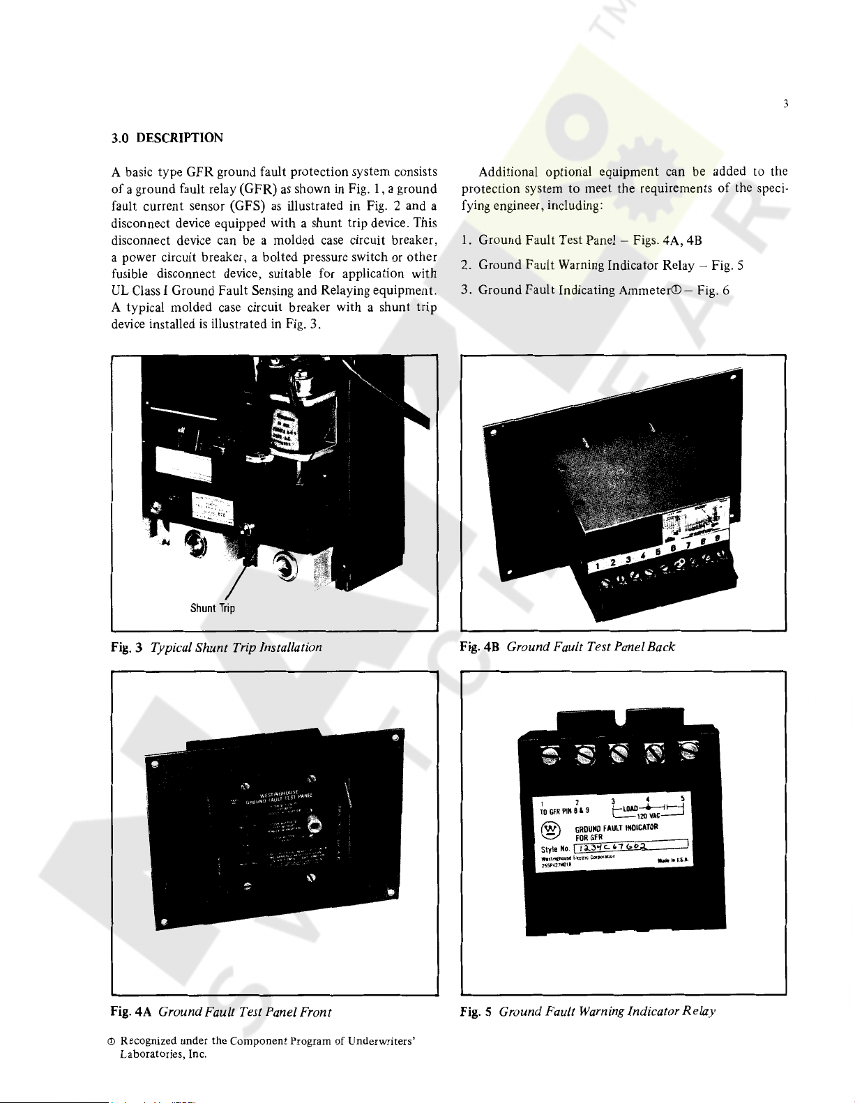
A basic type
of
a ground fault relay (GFR)
fault current sensor (GFS)
GFR
ground fault protection system consists
as
shown in Fig. 1, a ground
as
illustrated in Fig. 2 and a
disconnect device equipped with a shunt trip device. This
disconnect device can be a molded case circuit breaker,
a power circuit breaker, a bolted pressure switch or
fusible disconnect device, suitable for application
other
with
UL Class I Ground Fault Sensing and Relaying equipment.
A typical molded case circuit breaker with a shunt trip
device installed
is
illustrated in Fig. 3.
Additional optional equipment can be added to the
protection system
to
meet the requirements
of
the speci-
fying engineer, including:
1.
Ground Fault Test Panel - Figs. 4A,
4B
2. Ground Fault Warning Indicator Relay - Fig. 5
3. Ground
Fault
Indicating Ammeter© - Fig. 6
Shunt
Trip
Fig.
3 Typical Shunt Trip Installation
Fig.
4A Ground Fault Test Panel Front
Fig.
4B
Ground Fault Test Pane/Back
Fig.
5 Ground Fault Warning Indicator
Relay
© Recognized under the
Laboratories, Inc.
Component
Program
of
Underwriters'

4
Courtesy of NationalSwitchgear.com
Fig. 6 Ground Fault Indicating Ammeter
4.0
APPLICATION CONSIDERATIONS
4.1 General
Type
GFR
ground fault protective devices are designed
be used primarily
tion systems rated
Hz, to provide for rapid clearing
When properly applied, these devices will satisfy
requirements for ground fault
trance
517-14
vices are
as
gested in the fine
stream feeders as required in
tion will be provided and selective coordination
operations
equipment
downstream devices, a greater degree
service
4.2
There are two basic
nation
devices in a distribution system.
equipment
of
added
well as
With selectively coordinated ground fault
the
on
is
insured.
Methods
between
on
solidly grounded electrical distribu-
up
to a maximum
as outlined in Sections 230-95 and
the
National Electrical code. When these de-
to
downstream feeder and
main service disconnecting devices as sug-
print
note
of
of
600
volts,
of
arcing ground faults.
protection
230-95
and
of
branch
to
service en-
the down-
517 -14, additional protec-
of
arcing ground faults can be achieved.
protection
applied
of
on
main service disconnects and
of
Achieving System Selectivity
methods
different levels
of
achieving selective coordi-
of
ground fault protective
continuity
50/60
the
circuits
tripping
of
4.2. I TIME-CURRENT BAND SETTINGS
The first
rent pick-up settings
stream and downstream devices. When properly coordi-
method
employs adjustable time delay and cur-
to
achieve selectivity between up-
nated,
current
ping
upstream interrupting device tripping action can be ini-
tiated.
longest time delay settings
devices. This
always downstream.
downstream
band
operation
This
type
type
detection
setting
that
and clear the faulted circuit before any
of
coordination necessarily requires
of
coordination
devices will use a time-
will initiate a downstream trip-
to
be placed
on
is
fine
if
4.2.2 ZONE SELECTIVE INTERLOCK/NG
In
a system employing zone selective interlocking type
devices, selective
stream faults
With appropriate settings, downstream interrupting de-
vices will clear
device can operate. However,
locking, additional intelligence
grammed
to
allow for variations
quence
ground
to
tem
device upstream
the
tion,
possible because
clear
to
fault. A zone selective interlock coordinated sys-
provides for fast tripping
pre-set time delay settings. With this
the resulting systems damage level
the
fault as quickly as
4.2.2.I Zone Selective Interlock
Zone
interlock wiring is only applicable
lays equipped
Table 1. These relays are equipped
terminals which have
Terminal 8 -
10 -
11 -Input
To
make
mode,
all relays
ditional wiring connections are required. Typical connec-
tions for a main
circuits
be used for interlock wiring
stray
bus systems. Interlock wiring
bus
groupings.
is
illustrated in Fig. 7.
As shown
magnetic fields in switchboards with high ampacity
bars and separate from
coordination
by
the use
the
faulted circuit before any upstream
into
the
time-current
in
allow for alternate locations
of
the
the
interrupting devices are allowed
is
still achieved for down-
of
time-current
with
zone selective inter-
is
automatically pro-
coordination
the
pre-established tripping
of
the
nearest interrupting
arcing ground fault regardless
they
can respond.
Wiring
to
with
zone selective interlocking as
with
the
following function:
9 -
the
by
Common
Output
Input
must
with
Note l in Fig.
(Not
used on l 25V
signal
signal, time restraint
signal,
no
trip
relays function in a zone interlocking
be
of
the
interlocking
multiple feeders and multiple
7,
twisted pair wiring must
to
reduce
must
concentrated
be
the
routed
type
four additional
the upstream
the
faults are
band
settings.
scheme
of
the
arcing
of
protec-
is
the
lowest
type
GFR
shown
D-C
GFR's)
type
and
branch
influence
away from
control
wire
the
se-
of
to
re-
in
ad-
of
Zone
Courtesy of NationalSwitchgear.com
Zone
Notes:
I.
W1nng
Ground.
2.
Jumper
3.
Any
4.
All
I
3
Should
On
may
Quantity-Up
Relays
in a Zone
be
125VDC
be
Added
to
Twisted
Pair,
Number
GFR's
the
Wire
Between Terminals 9
50-Relays
may
Interlock
System
to
Terminal B
be
Wired
Must
5
Typical
s
Typical
GFR
Typicdl
Delay
GFR
GFR
Do
Mdlrl
Feeder
s
Brandi
s
Not
Time
Delay
Input
~
~
~
E
.=
14
or
16
AWG
With Maximum Distance Between
is
Not
Used.
on
Downstream
to
Provide a Single
Only
Type
and
in
be
10
Parallel
of
Interlocking
One
125VDC
Relays
to
Upstream Restraint
Source
Add
Time
First
1s
Delay
and
Allowed
per
Signal
Last
Dial
Zones
Setting
of
250
Otherwise.
Feet
Route
Relay
Separate
will
ln1t1ate
from
Trip
Power
Without
Conductors
Time
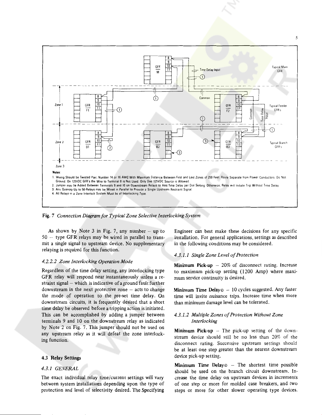
Fig. 7 Connection
As
shown by Note 3 in Fig. 7, any number - up
50 - type GFR relays may be wired in parallel
mit a single signal
is
relaying
required for this function.
Diagram
for Typical Zone Selective Interlocking System
to
to
upstream device. No supplementary
to
trans-
4.2.2.2 Zone Interlocking Operation Mode
Regardless
GFR
straint signal - which
of
the time delay setting, any interlocking type
relay will respond near instantaneously unless a
is
indicative
of
a ground fault further
re-
downstream in the next protective zone - acts to change
the mode
downstream circuits, it
time delay be observed before a tripping action
of
operation
to
the pre-set time delay. On
is
frequently desired
that
a short
is
initiated.
This can be accomplished by adding a jumper between
terminals 9 and 10
by Note 2 on Fig. 7. This jumper should
any upstream relay
on
the downstream relay
as
it will defeat the zone interlock-
not
as
be used
indicated
on
ing function.
4.3 Relay Settings
4.3.1 GENERAL
The exact individual relay time/current settings will vary
between system installations depending upon the type
protection and level
of
selectivity desired. The Specifying
of
Engineer can best make these decisions for any specific
installation. For general applications, settings
as
described
in the following conditions may be considered.
4.3.1.1 Single Zone Level
Minimum Pick-up -
to
maximum pick-up setting (1200 Amp) where maxi-
mum service continuity
20%
is
of
Protection
of
disconnect rating. Increase
desired.
Minimum Time Delay© - 10 cycles suggested. Any faster
time will invite nuisance trips. Increase time when more
than minimum damage level can be tolerated.
4.3.1.2 Multiple Zones
of
Protection Without Zone
Interlocking
Minimum Pick-up - The pick-up setting
stream device should still
be
no
less
than
of
the down-
20%
of
the
disconnect rating. Successive upstream settings should
be at least one step greater than the nearest downstream
device pick-up setting.
Minimum Time Delay© - The shortest time possible
on
should be used
crease the time delay
of
one step or more for molded case breakers, and two
the branch circuit downstream. In-
on
upstream devices in increments
steps or more for other slower operating type devices.
6
Courtesy of NationalSwitchgear.com
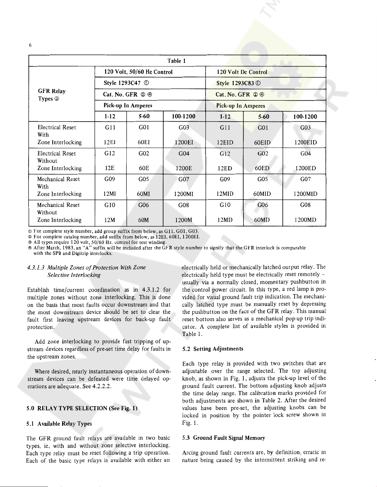
Table 1
GFR Relay
Types®
120 Volt,
Style 1293C47
Cat. No. GFR
50/60
Hz
<!)
@ @
Control
Pick-up In Amperes
Electrical Reset
1-12
Gll
5-60
GOl
100-1200
G03
With
Zone Interlocking
Electrical Reset
12EI
Gl2
60EI 1200EI 12EID 60EID 1200EID
G02 G04
Without
Zone Interlocking 12E
Mechanical Reset G09
60E 1200E 12ED 60ED 1200ED
GOS
G07 G09
With
Zone Interlocking 12MI
60MI
1200MI
Mechanical Reset GlO G06 G08 GlO
Without
Zone Interlocking
©For
complete style number, add group suffix from below,
@For
complete catalog number, add suffix from below,
@All types require 120 volt,
C!>
After March, 1983, an
with the
SPB
and Digitrip interlocks.
"A"
12M
50/60
Hz. control for test winding.
suffix will be included after the
60M
as
1200M 12MD
as
G11, GOl, G03.
12EI, 60EI, 1200£1.
GFR
style number to signify
De
120 Volt
Style l 293C83
Cat. No. GFR
Control
<D
<al
Pick-up In Amperes
1-12 5-60
Gl
l
Gl2
GOl G03
G02 G04
GOS
12MID
60MID 1200MID
G06 G08
60MD
that
the
GFR
interlock
@
is
comparable
100-1200
G07
1200MD
4.3.1.3 Multiple Zones
of
Protection
With
Zone
Selective Interlocking
Establish time/current coordination
multiple zones without zone interlocking. This
on the basis
that
most faults occur downstream and that
as
in 4.3.1.2 for
is
done
the most downstream device should be set to clear the
fault first leaving upstream devices for back-up fault
protection.
Add zone interlocking to provide fast tripping
stream devices regardless
of
pre-set time delay for faults in
of
up-
the upstream zones.
Where
desired, nearly instantaneous operation
of
down-
stream devices can be defeated were time delayed op-
erations are adequate. See 4.2.2.2.
5.0 RELAY TYPE SELECTION (See Fig. 1)
5
.1
Available Relay Types
The GFR ground fault relays are available in two basic
types, ie, with and without zone selective interlocking.
Each type relay must be reset following a trip operation.
of
Each
the basic type relays
is
available with either an
electrically held or mechanically latched
output
relay. The
electrically held type must be electrically reset remotely -
usually
the control power circuit. In this type, a red lamp
via
a normally closed, momentary pushbutton in
is
pro-
vided for visual ground fault trip indication. The mechani-
cally latched type must be manually reset by depressing
the pushbutton on the face
reset
bottom
also serves
cator. A complete list
Table
1.
of
the GFR relay. This manual
as
a mechanical pop-up trip indi-
of
available styles
is
provided
in
5.2 Setting Adjustments
Each type relay
is
provided with two switches that are
adjustable over the range selected. The top adjusting
knob,
as
shown in Fig. 1, adjusts the pick-up level
of
the
ground fault current. The bottom adjusting knob adjusts
the time delay range. The calibration marks provided for
both
adjustments
are
shown in Table 2. After the desired
values have been pre-set, the adjusting knobs can be
locked in position by the pointer lock screw shown in
Fig.
1.
5.3 Ground Fault Signal Memory
Arcing ground fault currents are, by definition, erratic
nature being caused by the intermittent striking and
in
re-
-++++--r+---
Courtesy of NationalSwitchgear.com
3~-·+
....
~---+---+--+++-»---r+----
2---.-+f-<
~~-+,1+---J_
1----.-~-+H
s~~~~
.._
5 r-t-·+
~+--
J:---------+-
01~
...-
--,,
005--
003----+-+--
DOI--·-
~
-+--4--+
._..
1---
-t-h-f---
~
t-t-
----------+--t+
-=---=1-
,_,_.---
- .
~
~--
-
--+!-<-
~
__:__:___-_-=_+--
-t-+--+
+
--
+---+I-+
i - -
----r---+
------+-----+--- t -+-+-+--
--+--
---+-
--+----+-
----+---1 ---+----t-+
t +
---+---
44
-
-+--
;.:-:H=-.-~:_:____
-:J-+-=--:--:-:---
-+-~·1
~+---;-----r-
'"
I;
t+
~-
+ • •
r-+-+
.,.
•---------+---+-
+ +
-+----+--f-+
+~
+----+---+-•
--+--+--
I
~
--+
+.
___
. -
+.
-+----.-
----~-~--+-!++~
_..,. •
------,-·
~
--r-~-
.,.
-----r_____._
-~-
-+--__,____,____+-....-
+--
•
•-+-
Cl
0 0 0 G
M
~
MINIMUM
PICK
~--...-----r----+-----+-
--+----1-t
-
·+~~---1-
I •
~
+ •
..
.....
~t-
· ·
+-
+
r-~~-~~
J--..-
~~==
....
-;--+--+-----
T--+---t
+•
--+--·
..
+-+----
t-
-
-+--
-;
----+---------~--+
r
--
1:
• j
1---
+-
-
.----+-+
. :-::-::t
0
UP
SEITINGS.
AMPERES
+-
+-
• --.-+---i-
...-+,-
.
so.
+.
--.-
-++---
...
+~-+--+-1-
....
--
+-----r-+-+r
-+
+---r--+---+-+
...
-+-+---+T-
+ t t +
·-
+
-
~
+- -
i.
-
t+----
+-+-
a
a
a
•
·---~10
L .
.
~--113
--
~.
·----.. -005
+
••. -002
++-~3
·-~-2
--1
·---02
••••
003
Fig.
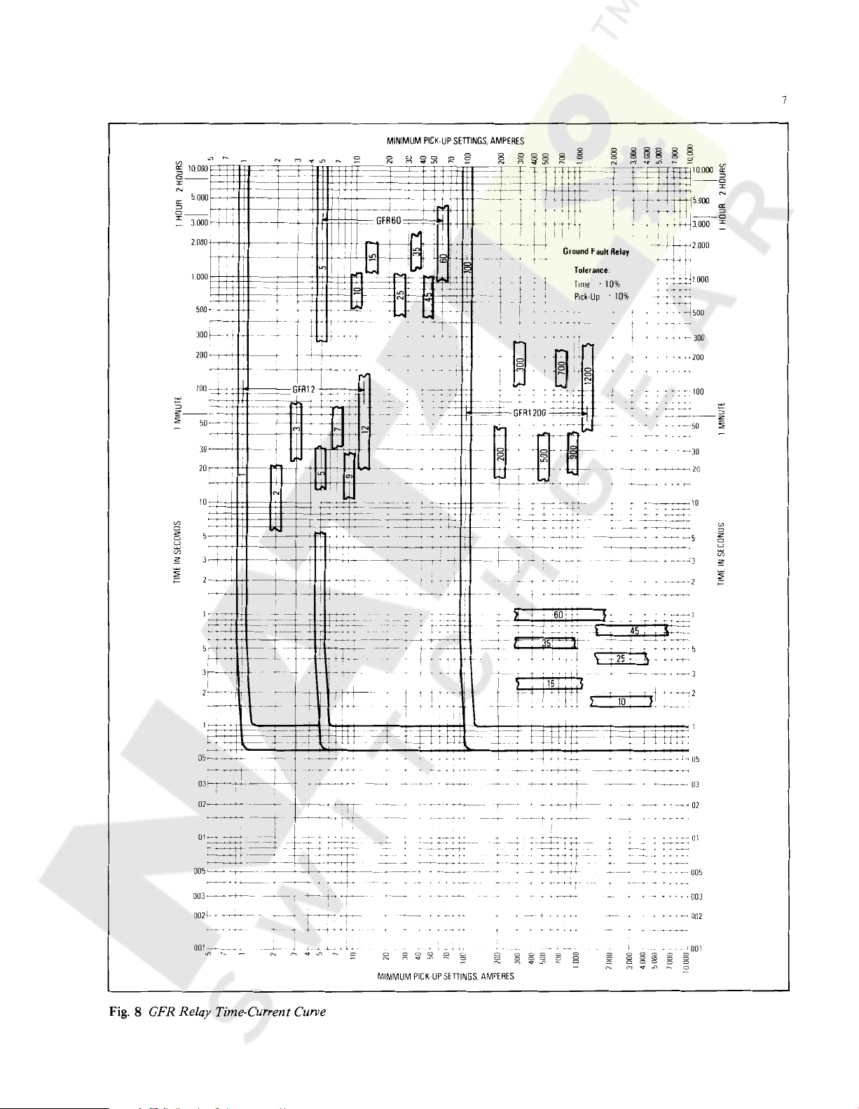
8 GFR Relay Time-Current Curve
8
Courtesy of NationalSwitchgear.com
striking
neous resetting
time the fault current drops
fault relays are equipped with a memory response, which
integrates these intermittent faults with time using a seven
second time constant.
*All Adjustments
5.4 Time-Current Curves
The time/current performance curve
lay has a flat response, ie., the operating time
fault current above its pick-up setting
stant. There
as
delay tolerances,
of
an arcing ground fault. To avoid the instanta-
of
the solid state timing circuitry every
to
zero, Type GFR ground
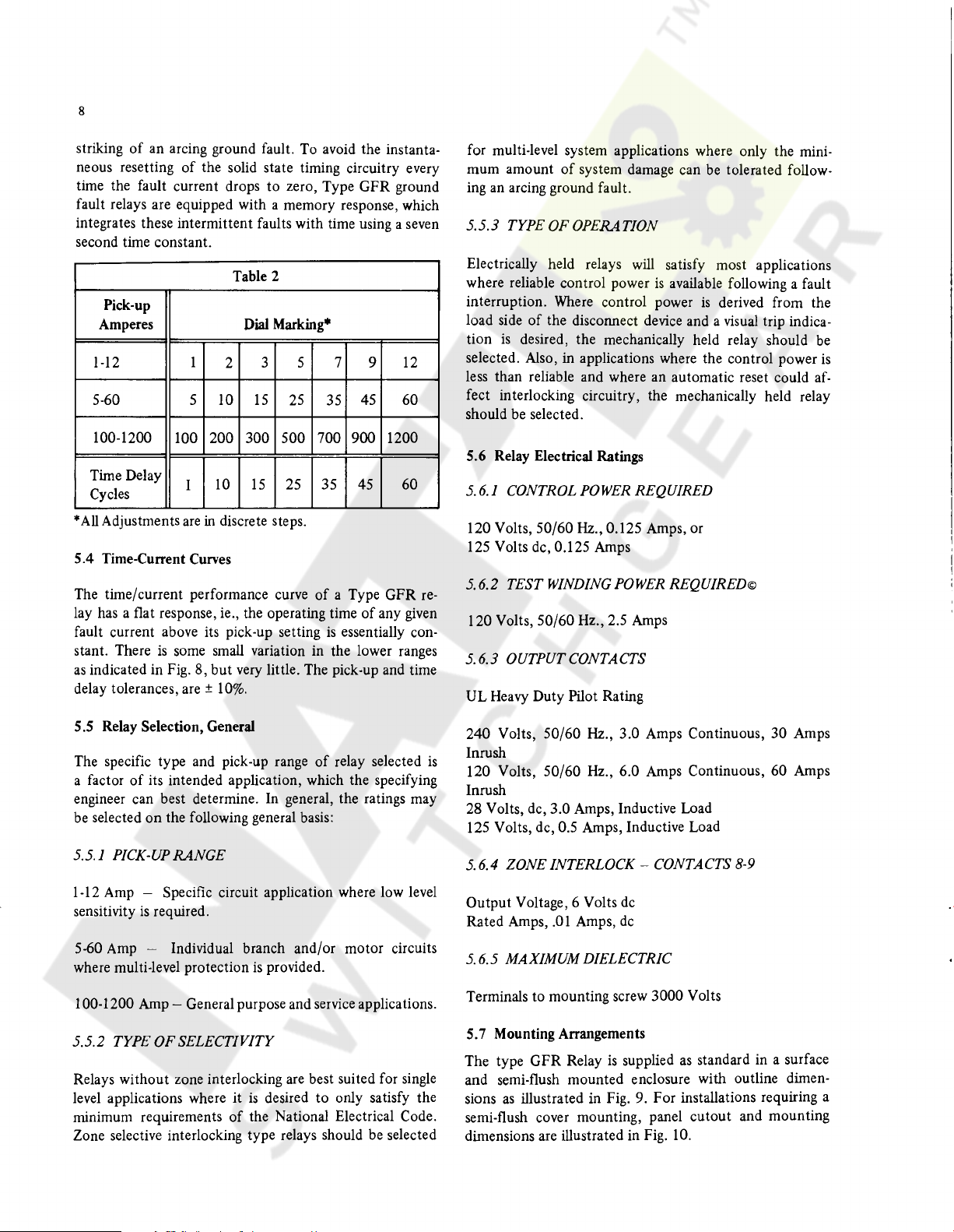
Table 2
Pick-up
Amperes
1-12 1
5-60 5 10
100-1200
Time Delay
Cycles
indicated in Fig. 8, but very little. The pick-up and time
100 200
I
are
is
some small variation in the lower ranges
are±
Dial Marking*
3 5 7
2
15
25 35
300 500
10
15
25
in discrete steps.
10%.
9 12
45
700
900
45
35
of
a Type GFR
of
is
essentially con-
60
1200
60
re-
any given
for multi-level system applications where only the mini-
mum amount
ing an arcing ground fault.
5.5.3
TYPEOFOPERATION
Electrically held relays will satisfy most applications
where reliable control power
interruption. Where control power
load side
tion
is
selected. Also, in applications where the control power
less than reliable and where an automatic reset could
fect interlocking circuitry, the mechanically held relay
should be selected.
5.6 Relay Electrical Ratings
5.
6.
I CONTROL POWER REQUIRED
120 Volts, 50/60
125 Volts de, 0.125 Amps
5.
6.2 TEST WINDING POWER REQUIRED©
120 Volts, 50/60 Hz., 2.5 Amps
of
system damage can be tolerated follow-
is
available following a fault
is
derived from the
of
the disconnect device and a visual trip indica-
desired, the mechanically held relay should be
af-
Hz.,
0.125 Amps, or
5.6.3 OUTPUTCONTACTS
UL Heavy Duty Pilot Rating
is
5
.5
Relay Selection, General
The specific type and pick-up range
a factor
engineer can best determine. In general, the ratings may
be selected
5.5. I PICK-UP
1-12 Amp - Specific circuit application where low level
sensitivity
5-60 Amp - Individual branch and/or motor circuits
where multi-level protection
100-1200 Amp - General purpose and service applications.
5.5.2 TYPE OF
Relays without zone interlocking are best suited for single
level applications where it
minimum requirements
Zone selective interlocking type relays should be selected
of
its intended application, which the specifying
on
the following general basis:
RANGE
is
required.
is
provided.
SELECTIVITY
is
desired
of
the National Electrical Code.
of
relay selected
to
only satisfy the
240 Volts, 50/60
Inrush
is
120 Volts, 50/60 Hz., 6.0 Amps Continuous, 60 Amps
Inrush
28 Volts, de, 3.0 Amps, Inductive Load
125 Volts, de, 0.5 Amps, Inductive Load
Hz.,
3.0 Amps Continuous, 30 Amps
5.6.4 ZONE INTERLOCK - CONTACTS 8-9
Output Voltage, 6 Volts de
Rated Amps,
5.
6.5 MAXIMUM DIELECTRIC
Terminals to mounting screw 3000 Volts
5.7 Mounting Arrangements
The type GFR Relay
and semi-flush mounted enclosure with outline dimen-
as
sions
semi-flush cover mounting, panel cutout and mounting
dimensions are illustrated in Fig. 10.
.01
Amps,
de
is
supplied
illustrated in Fig. 9. For installations requiring a
as
standard in a surface
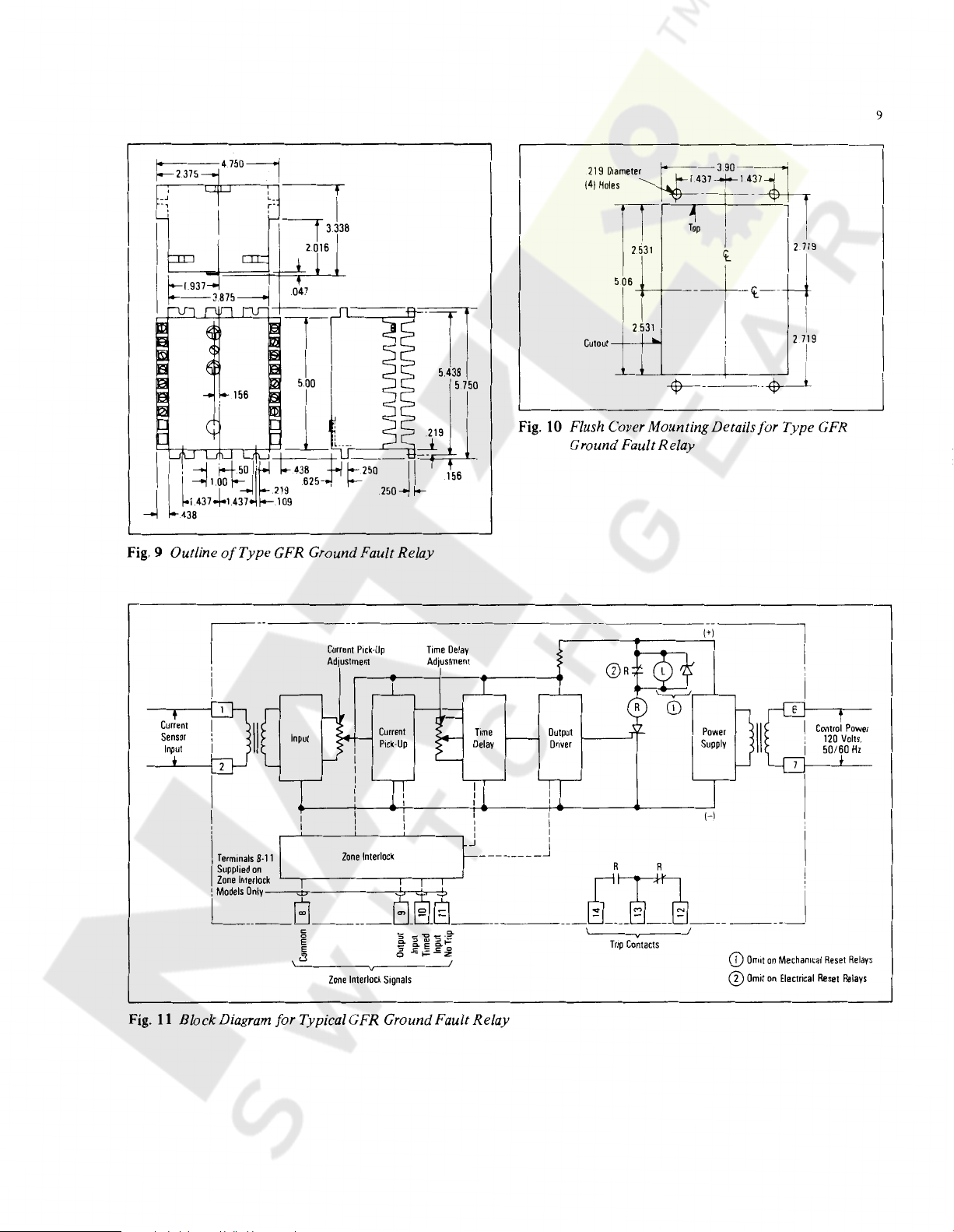
Fig.
Courtesy of NationalSwitchgear.com
i:-:
2.375
9 Outline
of
Type GFR Ground Fault Relay
Fig.
2
531
Cutout
--'----'--'--+------_-_
10
Flush Cover Mounting Details for Type GFR
Ground Fault Relay
__...__
-_-_-_-:_-$--'
T
9
I
Fig.
Current
Pick-Up
Adjustment
Current
Sensor
Input
Zone
Zone
Interlock
Interlock
Terminals
8-11
Supplied
on
Zone
Interlock
c~-n-ly
11
Block Diagram for Typical GFR Ground Fault Relay
~----8_§_@
Signals
Time
Delay
Adjustment
______
I
I
I
I
_J
________
Output
Driver
I
I
I
I
I
_J
I-----'
R
r D
@]
____
~
---
Trip
Contacts
(+)
Power
Supply
(-)
~
______
G)
Omit
(D
Omit
j
on
Mechanical
on
Electrical
Control
120
50/60
Reset
Reset
Power
Volts.
Hz
Relays
Relays
 Loading...