

Page 1
Installation Instructions
Vertical Wall Mount Air Handler
These instructions are primarily intended to assist qualifi ed individuals experienced in the proper
installation of heating and/or air conditioning appliances. Some local codes require licensed
installation/service personnel for this type equipment. All installations must be in accordance with
these instructions and with all applicable national and local codes and standards.
Before beginning the installation, read these instructions thoroughly and follow all warnings and
cautions in the instructions and on the unit. When performing brazing operations have a fi re
extinguisher readily available and use a quenching cloth and brazing shield.
Improper installation, service, adjustment, or maintenance can cause fi re, electrical shock or other
conditions which may result in personal injury or property damage. Unless otherwise noted in
these instructions, only factory authorized kits or accessories may be used when modifying this
product.
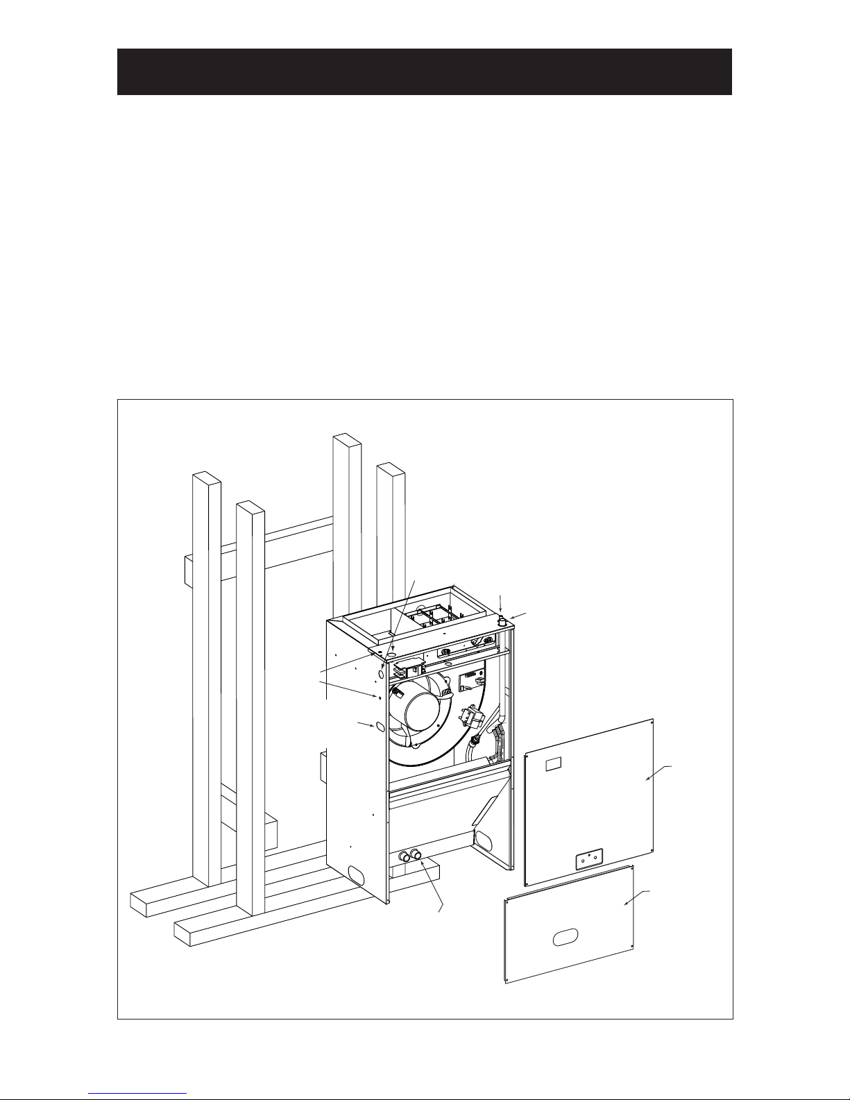
LOW
VO LTAGE
OPTIONAL
LEFT/RIGHT
REFRIGERANT
LINE ENTRIES
FRONT PRIMARY AND SECONDARY
DRAINS CAN BE ACCESSED THROUGH
THE BOTTOM OR LEFT/RIGHT SIDE
OF UNIT 3/4" NPT MALE CONNECTION
POWER
ENTRY
LIQUID
LINE
SUCTION
LINE
ACCESS
PANEL
FRONT OR
BOTTOM
PANEL
Figure 1.
Page 2

2
Page 3
1. INSTALLATION
Units are approved for closet or alcove installation with zero clearance to combustibles. Units
are designed to be installed either recessed into
a wall or hanging in a vertical “upfl ow” position.
If units are recessed in a wall, attachment to
the framing studs are through the inside of the
front fl ange. Air handlers are provided with an
offset hanging bracket attached to the rear of
the cabinet for hanging applications.
Units have a bottom and/or front return. Units
are shipped for installation in a front return
application. Front close-off panel (if supplied)
may be discarded. If installed in a bottom return application, attach bottom access to the
front of the unit below the top service panel or
close-off panel.
- If no pressure is found, test coil for leak
- If no leak is found, install coil
- If leak is found, clearly mark leak
location and return coil to your distributor
for processing
3. REFRIGERANT LINE
CONNECTIONS
Note: Do not remove seals from the coil until
tubing connections are ready to be made.
Note: The air handler coil does not contain
a refrigerant charge. Reference installation
instructions included with outdoor unit for
information regarding the refrigerant charge
included in the outdoor unit.
Units are equipped with primary and secondary
drains and both drains must be trapped. Failure
to install a trap could result in condensation
overfl owing the drain pan resulting in substantial
water damage to the nearby area.
Note: If you intend to install this unit with a
louvered door the unit must be mounted fl ush
or behind front edge of fi nished wall.
2. VERIFY PRESSURIZATION
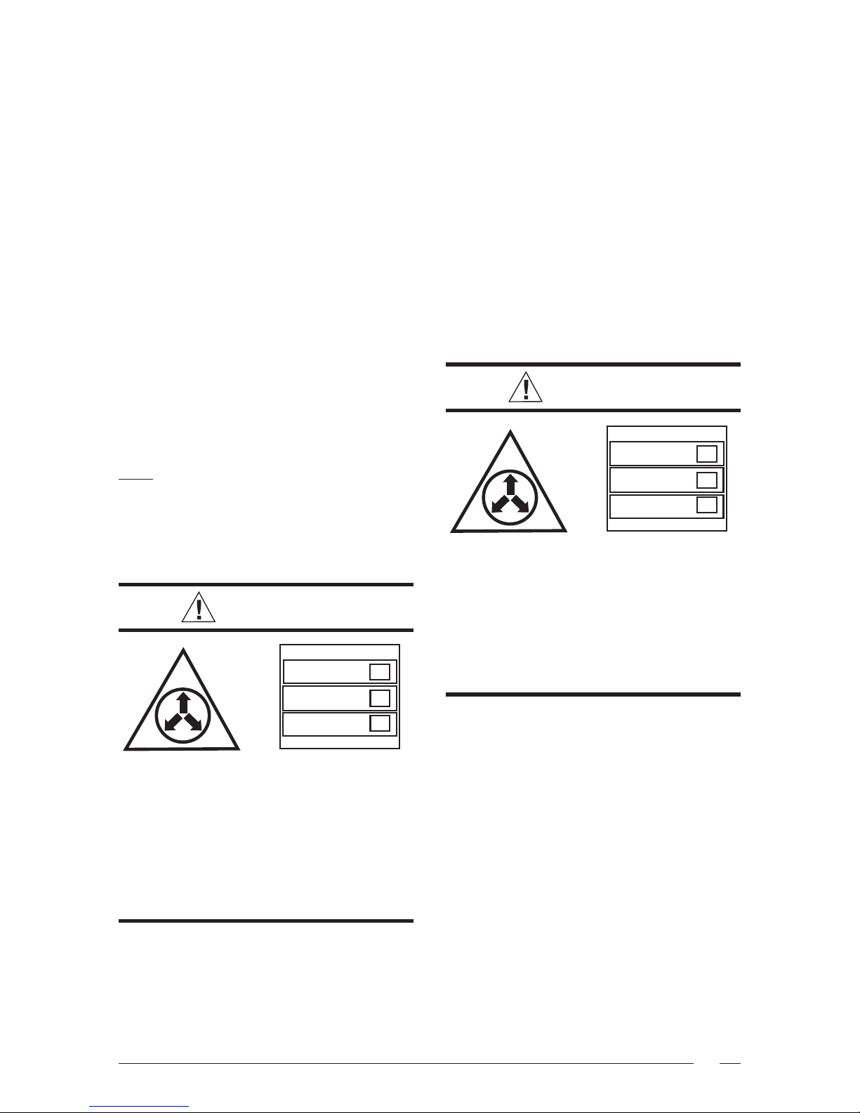
WARNING:
NITROGEN
HEALTH
FLAMMABILITY
REACTIVITY
0 Minimal Hazard
This coil is pressurized with Nitrogen.
Avoid direct face exposure or contact
with valve when gas is escaping. Always ensure adequate ventilation is
present during the depressurization
process. Any uncertainties should be
addressed before proceeding.
VERIFY PRESSURIZATION:
- Test by depressing Schrader valve and listen
for escaping gas
1
0
0
1 Slight Hazard
WARNING:
NITROGEN
HEALTH
FLAMMABILITY
REACTIVITY
0 Minimal Hazard
This coil is pressurized with Nitrogen.
Avoid direct face exposure or contact
with valve when gas is escaping. Always ensure adequate ventilation is
present during the depressurization
process. Any uncertainties should be
addressed before proceeding.
1. Remove cap from Schrader valve on liquid
line. Relieve all pressure from the coil by
depressing the valve on the end of the
liquid line. Remove the valve core. Properly
dispose of all removed parts.
2. Loosen the distributor body halves by
applying two wrenches and turning the
assembly nut counterclockwise.
3. When separated insert a light-gauge wire
hook between the distributor body and the
restrictor orifi ce and carefully remove the
restrictor orifi ce being careful not to scratch
either part.
4. Insert the new restrictor orifi ce in the
distributor body.
5. After installing the orifi ce in the distributor
body, re-attach the assembly nut to the
1
0
0
1 Slight Hazard
3
Page 4
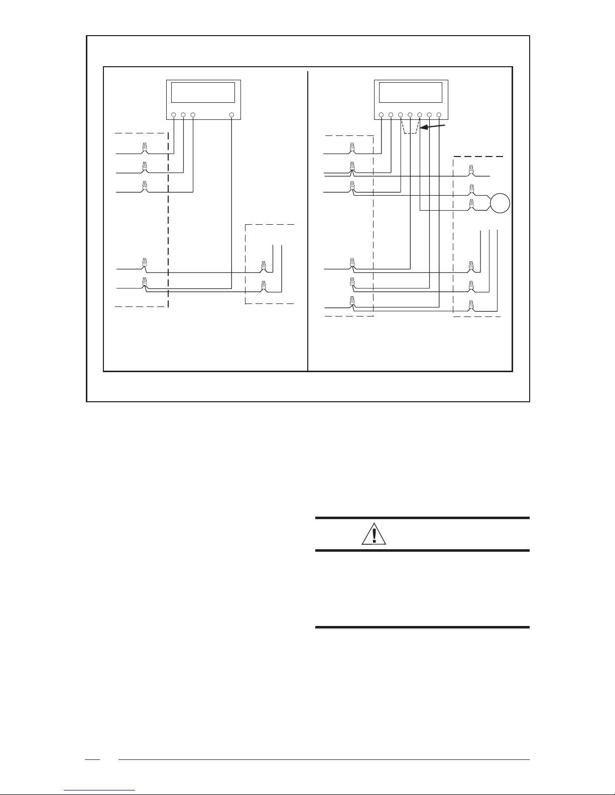
Green
G
Thermostat
GRW
Thermostat
Y
Green
GRW2CEOY
G
NOTE: Jumper
between W2 and E is
required when no OD
T-Stat is used.
Red
White
Grey
Yellow
R
W
1
YC
CC
Air Handler A/C OD Section
Typical Air Conditioner w/Air Handler
Red
White
Grey
Yellow
Air Handler Heat Pump OD
R
W
1
Typical Heat Pump w/Air Handler
Figure 2. Typical Air Conditioning and Heat Pump System Connections
W
E
C
Section
2
O Y
R
OD
Stat
distributor body and tighten it to 10-12 ft./lbs
of torque. If no torque wrench is available,
hand tighten and then tighten an additional
1/4 turn.
6. If not already done so, release pressure
from the coil by removing the valve cap
and then depressing the valve on the end
of the liquid line. Remove the valve core
and dispose of properly.
7. Unbraze and remove the cap on the suction
line. Unbraze and remove the valve core
holder on the liquid line.
8. Cut the line set tubing to the proper length.
Be sure that the tubing has been sized in
accordance with the outdoor unit specifi cations.
9. Inspect both refrigerant lines. The ends of
the lines must be round, clean, and free of
any burrs.
10. Insert the line set tubes into the coil tube
stubs until they bottom out.
11. Braze the individual connections with dry
nitrogen fl owing through the joints to eliminate internal oxidation and scaling.
12. Check the assembly for leaks.
13. Properly dispose of all removed parts.
WARNING:
To avoid the risk of electric shock,
personal injury or death, disconnect all electrical power to the unit
before performing any maintenance
or service.
4. ELECTRICAL WIRING
General — Electrical power wiring must be made
in accordance with all applicable local codes and
ordinances, and with the current revision of the
National Electric Code (ANSI/NFPA 70). If any of
the original wire as supplied with the unit must be
replaced, it must be replaced with wire material
having the same gauge and temperature rating.
4
Page 5
Use a separate branch electrical circuit for this
unit. See the unit wiring label for proper high
and low voltage wiring.
208/240 volt units are shipped from the factory
wired for 240 volt transformer operation. For
208 volt operation, remove the lead from the
transformer terminal marked 240v and connect
it to the terminal marked 208v.
the factory set blower speed, disconnect all
electrical power to the unit and remove the upper
door. Remove the green wire from the blower
motor terminal. Connect the green wire to the
desired blower speed marked on the terminal
block of the blower motor. Terminal 5 = Hi speed,
terminal 4 = Med Hi speed, terminal 3 = Med
speed, terminal 2 = Med low speed, terminal
1 = Low speed.
Provide power supply for the unit in accordance
with the unit wiring diagram and the unit rating
plate. Use copper wire only for the line voltage
power supply to this unit.
Check all factory wiring per the unit wiring
diagram and inspect the factory wiring connections to be sure none were loosened in transit
or installation.
Some units are equipped with a liquid line
solenoid valve. Connect the loose yellow wire
to the Y1 thermostat wire as shown in the wiring diagram.
Refer to Figure 2 for typical low voltage system
wiring.
CAUTION:
Make sure all doors are installed before restoring power to the unit.
5. START-UP AND ADJUSTMENT
Selecting Proper Blower Speed for MultiSpeed Units — The blower speed is preset
at the factory for operation at the same speed
for heating and cooling. For optimum system
performance and comfort, it may be necessary
to change the factory set speed. To change the
blower speed, disconnect all electrical power to
the unit and remove the upper door. Remove
the black wire from the blower motor terminal.
Connect the black wire to the desired blower
speed marked on the terminal block of the blower
motor. Terminal 5 = Hi speed, terminal 4 = Med
Hi speed, terminal 3 = Med speed, terminal 2 =
Med Low speed, terminal 1 = Low speed. See
Table 1 for airfl ow data.
Replace the upper door and secure it to the
unit. Restore power to the unit.
Selecting Blower Speed for Fan Only Operation — Units are equipped with the capability of
selectable fan only blower speeds. To change
Replace the upper door and secure it to the
unit. Restore power to the unit.
6. CARE AND MAINTENANCE
General — For continued high performance,
and to minimize the risk of equipment failure, it
is essential that periodic maintenance be performed on this equipment. The ability to properly
perform maintenance on this equipment requires
certain mechanical skills and tools. If you do not
possess these skills, contact your dealer for
maintenance. Consult your local dealer as to
the availability of a maintenance contract.
Do not store any of the following on, or in contact
with, the unit: Rags, brooms, vacuum cleaners,
or other cleaning tools, spray or aerosol cans,
soap powders, bleaches, waxes, cleaning
compounds, plastics or plastic containers,
paper bags or other paper products, gasoline,
kerosene, cigarette lighter fl uid, dry cleaning
fl uids, paint thinners, or other volatile fl uids.
Proper maintenance is most important to achieve
the best performance from an air handler. At a
minimum, this maintenance should include the
following items.
1. Inspect and clean or replace the air fi lter at
the beginning of each heating and cooling
season, or more frequently as required.
2. Inspect the cooling coil, drain pan, and
condensate drain at the beginning of each
cooling season for cleanliness. Clean these
components as necessary using a mild
detergent and water. Flush the coil, drain
pan, and condensate drain after cleaning
to remove all detergent. Use caution when
cleaning these components so that the
insulation does not become wet.
3. Inspect the blower motor and wheel for
cleanliness at the beginning of each heating and cooling season. Clean the motor
as necessary.
4. Inspect electrical connections for tightness
at the beginning of each heating and cooling
season. Service as necessary.
5
Page 6
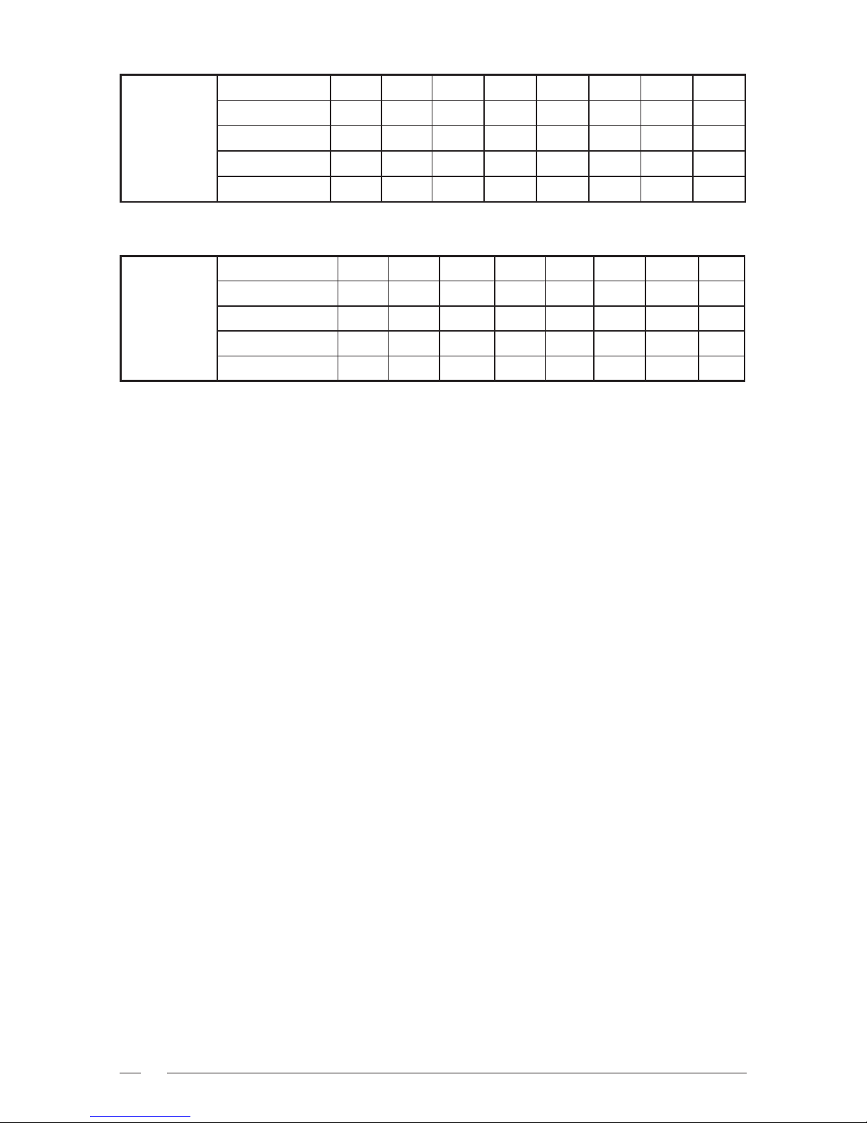
Dry Coil ESP 0.10 0.20 0.30 0.40 0.50 0.60 0.70 0.80
Low 640 597 553 529 492 452 428 388
Med-Low 721 691 652 624 584 554 528 487
018K/024K
Medium 830 795 760 737 702 666 649 613
Med-High 929 906 881 844 817 771 718 663
High 1074 1018 975 925 868 811 753 694
Dry Coil ESP 0.10 0.20 0.30 0.40 0.50 0.60 0.70 0.80
Low 596 568 525 481 450 401 357 331
Med-Low 689 652 614 587 546 505 474 433
030K
Medium 786 746 706 675 629 597 561 530
Med-High 885 862 830 804 770 736 709 658
High 1153 1110 1061 1011 956 902 837 763
Notes:
1) Airfl ow is shown in cfm, +/- 5%.
2) External static pressure is shown in inches w.c.
3) All airfl ows are measured with fi lter and with dry coil. For wet coil, subtract .1" external static pressure.
4) See unit nameplate or installation instructions for maximum recommended external static pressure.
Figure 1. System Airfl ow Data
6
Page 7

7
Page 8

INSTALLER:
PLEASE LEAVE THESE
INSTALLATION INSTRUCTIONS
WITH THE HOMEOWNER
¢708708@¤
Specifi cations and illustrations subject to change
708708B (Replaces 708708A)
without notice and without incurring obligations.
Printed in U.S.A. (10/07)
 Loading...