

Page 1
USER MANUAL
20
5.3
7600/10000
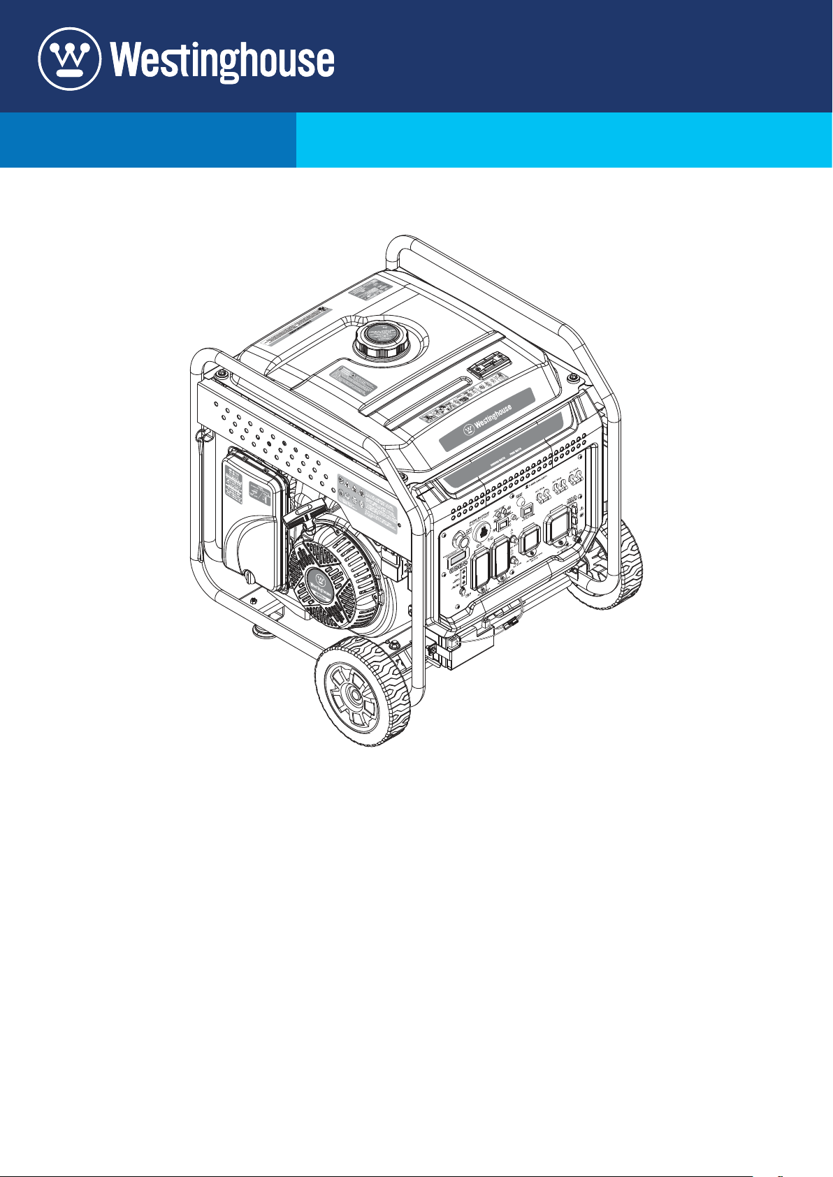
ecoGen10000
PORTABLE GENERATOR
7600 RUNNING WATTS | 10000 PEAK WATTS
DO NOT RETURN THIS PRODUCT TO THE STORE
If you have questions or need assistance, please call customer
service at 855-944-3571.
Page 2
TABLE OF CONTENTS
Introduction .............................................................................................................................................................................2-3
Safety ...................................................................................................................................................................................4-10
Electrical ............................................................................................................................................................................. 11-12
Components .......................................................................................................................................................................13-14
Assembly ............................................................................................................................................................................15-16
Operation ............................................................................................................................................................................17-24
Care and maintenance .......................................................................................................................................................25-31
Troubleshooting ....................................................................................................................................................................... 32
Exploded Views ..................................................................................................................................................................33-36
Service Hotline/Company Address .............................................................................................................................Back Page
INTRODUCTION
WARNING
taining this equipment can expose you to chemicals
including engine exhaust, carbon monoxide, phthalates, and lead, which are known to the State of
California to cause cancer and birth defects or other reproductive harm. To minimize exposure, avoid
breathing exhaust, and wear gloves or wash your
hands frequently when servicing this equipment. For
more information go to www.P65warnings.ca.gov.
Operating, servicing, and main-
DISCLAIMERS
All information, illustrations, and specications in this
manual were in effect at the time of publishing. The illustrations used in this manual are intended as representative
reference views only. We reserve the right to make any
specication or design change without notice.
ALL RIGHTS RESERVED
All rights reserved. No reproduction allowed in any form
without written permission from Westinghouse Outdoor
Power Equipment.
DANGER
using or performing maintenance on this product. Failure to follow the instructions and safety
precautions in this manual can result in serious
injury or death.
Read this manual before
UPDATES
The latest User Manual for your Westinghouse products
can be found under our support tab. https://westinghou-
seoutdoorpower.com/pages/manuals
Or scan the following QR code with your smartphone camera to be directed to the link.
PRODUCT REGISTRATION
For trouble-free warranty coverage, it
is important to register your Westinghouse product.
You can register by:
l Completing and mailing the product
registration card included in the
carton.
l Registering your product on-line at:
https://westinghouseoutdoorpower.com/pages/
warranty-registration
l Scanning the above QR code with your smartphone
camera to be directed to the mobile registration link.
For Your Records
Date of Purchase:
Model Number:
Serial Number:
Place of Purchase:
l Sending the following product information to:
Westinghouse Outdoor Power
Warranty registration
777 Manor Park Drive
Columbus, OH 43228
IMPORTANT: Keep your purchase receipt for trouble-free
warranty coverage.
2 | English
Page 3

INTRODUCTION
SPECIFICATIONS
AC Voltage.......................................................120V/240V
Power (Running).................................................... 7600W
Power (Peak) ....................................................... 10000W
Frequency................................................................ 60 Hz
Phase ..................................................................... Single
RPM .......................................................................... 3600
Power Factor ............................................................... 1.0
Insulation Class .............................................................. F
Maximum Ambient Temperature .................. 104°F (40°C)
Fuel Type .............................................Unleaded gasoline
87 – 93 Octane*
Fuel Capacity................................. 5.28 gallons (20 liters)
Oil Capacity ................................... 1.16 quarts (1.1 liters)
Oil Type ........................................................SAE 10W-30
Spark Plug ......................................................Torch F7TC
Spark Plug Gap .......................................0.024 – 0.032 in.
(0.60 – 0.80 mm)
Valve Intake Clearance ........................0.0031 – 0.0047 in.
(0.08 – 0.12 mm)
Valve Exhaust Clearance ....................0.0051 – 0.0067 in.
(0.13 – 0.17 mm)
AC Grounding System ............................ Bonded to frame
NOTICE
for continuous operation at ambient temperatures up
to 104°F (40°C). If needed, this product can be op-
erated at temperatures ranging from 5°F (–15°C) to
122°F (50°C) for short periods. If the product is exposed to temperatures outside of this range during
storage, it should be brought back within this range
before operation. This product must always be operated outdoors in a well- ventilated area and far away
from doors, windows, and other vents.
Maximum wattage and current are subject to and
limited by such factors as fuel BTU content, ambient
temperature, altitude, engine conditions, etc. Maximum power decreases about 3.5% for each 1,000
feet above sea level, and will also decrease about 1%
for each 10°F (6°C) above 60°F (16°C) ambient temperature.
This product is designed and rated
HAVE QUESTIONS?
Email us at [email protected]
NOTICE
tion, engine horsepower will decrease about 3.5%
for each 609.6 meter (2,000 foot) increase in altitude.
The effect of altitude on horsepower will be greater
if no carburetor modication is made. A decrease in
engine horsepower will decrease the power output of
the generator. Contact our service team to order altitude kits.
NOTICE
house! PLEASE READ BEFORE RETURNING THIS
PRODUCT FOR ANY REASON.
If you have a question or experience a problem with your Westinghouse purchase, call us at
1-855-944-3571 to speak with an agent.
SAVE THIS MANUAL FOR FUTURE REFERENCE.
Even with a carburetor modica-
Thank you for choosing Westing-
or call 1-855-944-3571
English | 3
Page 4
SAFETY
SAFETY DEFINITIONS
The words DANGER, WARNING, CAUTION, and NOTICE
are used throughout this manual to highlight important
information. Make sure that the meanings of this safety
information is known to all who operate, perform maintenance on, or are near the generator.
This safety alert symbol appears with
most safety statements. It means attention, become alert, your safety is
involved! Please read and abide by the
message that follows the safety alerts
symbol.
DANGER
which, if not avoided, will result in death or serious
injury.
WARNING
which, if not avoided, could result in death or serious
injury.
CAUTION
which, if not avoided, could result in minor or moderate injury.
Indicates a hazardous situation
Indicates a hazardous situation
Indicates a hazardous situation
SAFETY SYMBOLS
Follow all safety information contained in this user’s manual
as well as the information on the product labeling.
SYMBOL
Safety Alert Symbol
Fire Hazard
Electrical Shock Hazard
Burn Hazard. Do not touch hot surfaces.
Asphyxiation Hazard
Do Not Operate in Wet Conditions
DESCRIPTION
NOTICE
Indicates a situation which can
cause damage to the generator, personal property,
and/or the environment, or cause the equipment to
operate improperly.
NOTE: Indicates a procedure, practice or condition that
should be followed for the generator to function in the
manner intended.
5 FEET (1.5m)
MINIMUM
FROM OBJECTS
CARBON
CO
MONOXIDE
Read Manufacturer’s Instructions
Maintain Safe Distance
Ground. Consult with electrician to determine grounding requirements before
operation.
Carbon Monoxide
4 | English
Page 5
SAFETY
IMPORTANT SAFETY INSTRUCTIONS
DANGER
high levels of carbon monoxide (CO), an invisible,
odorless, and extremely poisonous gas. If you smell
exhaust fumes, you are breathing carbon monoxide.
But, even if you do not smell exhaust fumes you may
be inhaling CO.
ONLY operate generators outside, in a well-ventilated
area. NEVER operate generators indoors, doing so
CAN KILL YOU IN MINUTES.
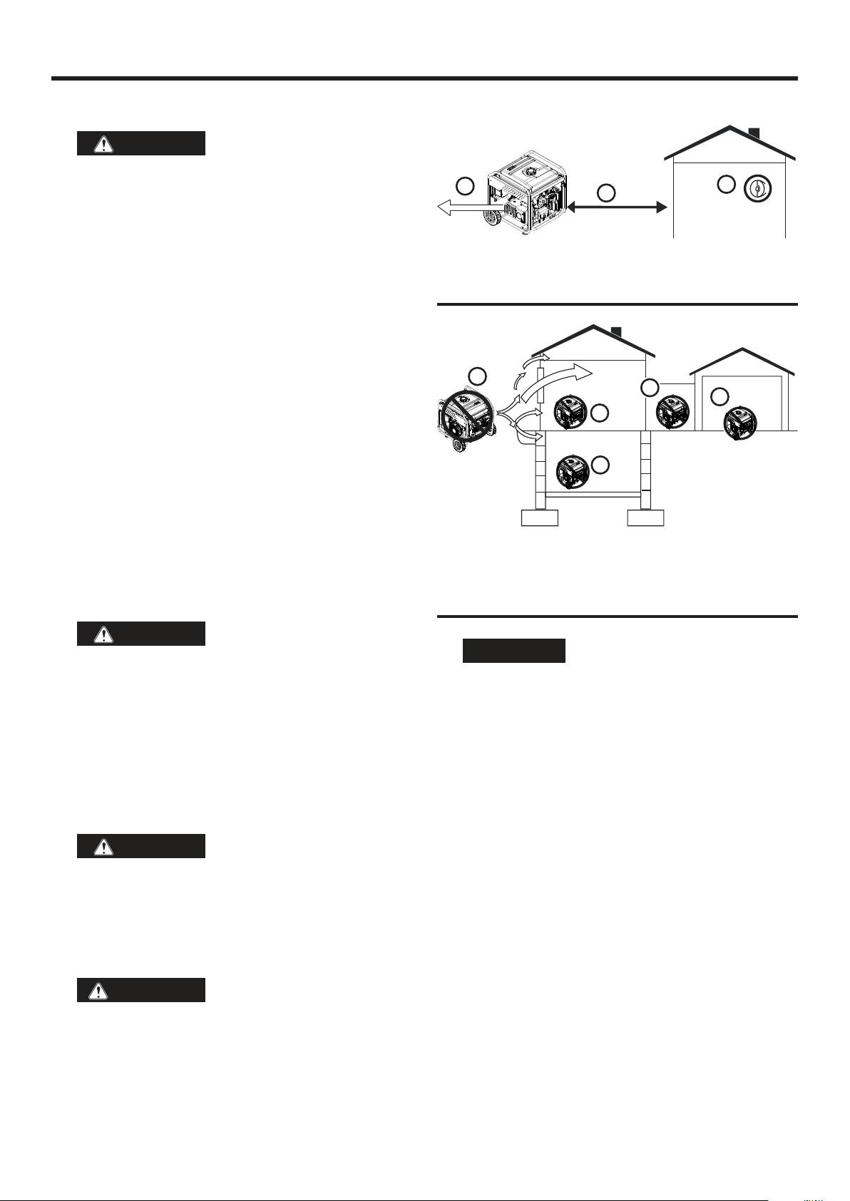
• Correct Use – ONLY use generators outside and
downwind, far away from windows, doors and vents.
ALWAYS direct exhaust away from occupied spaces. ALWAY S install battery-powered carbon monoxide detectors or plug-in carbon monoxide detectors
with battery back-up in living areas. See Figure 1.
• Incorrect Use – NEVER use a generator in your
home, garage, basement, attic, crawl space or any
other fully or partially enclosed area. Areas such as
these can allow dangerous levels of carbon monoxide to accumulate. An open door or a running
fan WILL NOT provide adequate ventilation. See
Figure2.
If you start feeling dizzy, weak, or sick while using the
generator, move to fresh air IMMEDIATELY. Contact
a doctor. You may be experiencing carbon monoxide
poisoning.
Generator exhaust contains
FIG. 1
A
A - Exhaust (CO)
B - Only use OUTSIDE and FAR AWAY from windows, doors, and vents
C - CO detectors in living areas
B
C
FIG. 2
A
RUN
CH
OKE
OFF
A - Exhaust (CO)
B - Living area
C - Basement crawlspace
D - Entryway/porch/mudroom
E - Garage
B
C
D
E
DANGER
Fire and electrocution hazard.
Do not connect to a building’s electrical system unless the generator and a transfer switch have been
properly installed and the electrical output has been
veried by a qualied electrician. The connection
must isolate the generator power from utility power
and must comply with all applicable laws and electrical codes. Failure to properly isolate the generator
power could cause property damage and create a
dangerous backfeed of electricity which could kill or
seriously injure utility workers.
DANGER
Electrocution hazard. NEVER
use the generator in a location that is wet or damp.
Never expose the generator to rain, snow, water
spray, or standing water while in use. Protect the generator from all hazardous weather conditions. Moisture or ice can cause a short circuit or other malfunction in the electrical circuit.
WARNING
Familiarize yourself with all the
instructions, safety warnings, illustrations, and spec-
ications provided with this product. Failure to follow
the manufacturer’s instructions may result in electric
shock, re, and/or carbon monoxide poisoning that
can lead to death or serious injury.
NOTICE
Install battery-powered carbon monoxide detectors or plug-in carbon monoxide detectors
with battery back-up in living areas.
l This product should ONLY be used outdoors.
l NEVER use a generator in your home, garage, basement,
attic, crawl space or any other fully or partially enclosed
area. Areas such as these can allow dangerous levels
of carbon monoxide to accumulate. Carbon monoxide
(CO), an invisible, odorless, and extremely poisonous
gas CAN KILL YOU IN MINUTES.
l Only use OUTSIDE and far away from windows, doors,
and vents as recommended by the US Department of
Health and Human Services Centers for Disease Control
and Prevention. Your specic home and/or wind conditions
may require additional distance.
l The National Electrical Code requires the use of a transfer
switch or other suitable transfer equipment whenever a
portable generator is connected to a building’s electrical
system. Transfer switches isolate generator power from
utility power and prevent backfeeding of electric power
into the utility system.
NOTE: A transfer switch must be installed by a quali-
ed electrician in accordance with applicable electrical
codes. Some jurisdictions may require the installation
English | 5
Page 6

SAFETY
to be inspected by local authorities. Keep all relevant
installation, inspection, and maintenance information.
l Never use the generator to power medical support equip-
ment.
l Never expose the generator to rain, snow, water spray,
or standing water while in use. Store and operate the
unit in a dry or covered (but not enclosed) location.
l Do not let children or untrained individuals operate the
generator.
l Keep children, bystanders, and pets a minimum of 10 ft.
away from a running generator.
l Maintain Safe Distance. While operating and storing,
keep at least ve feet of clearance on all sides of the
generator, including overhead. Turn the unit off and allow
it to cool a minimum of 30 minutes before storage. Heat
created by the mufer and exhaust gases could be hot
enough to cause serious burns and/or ignite combustible
objects.
l Do not operate the unit in areas where combustible or
hazardous materials are stored including gasoline and
natural gas lling stations.
l Do not operate the generator while barefoot, with wet
hands or feet, while standing in water or in wet conditions.
l Do not use this unit when you are tired or under the
inuence of drugs, alcohol, or medication.
l Burn Hazard. Do not touch hot surfaces.
l Do not contact the mufer or engine. They are very HOT
and will cause severe burns. Do not put body parts or any
ammable or combustible materials in the direct path of
the exhaust.
l Keep hands, ngers, feet, and other body parts away
from all moving parts of the generator.
l Do not connect worn or damaged electrical cords to the
generator. NEVER touch frayed or exposed wires.
l Do not operate the generator on an incline. The unit
should always be placed on a at, stable surface with a
slope no greater than 4°.
l Check the physical condition of the product prior to each
use. Look for loose bolts, uid leaks, and other signs of
wear. Replace all damaged items. For replacement parts
or assistance, contact our customer service team.
l For optimal performance, use the generator in tem-
peratures between 23°F (-5°C) and 104°F (40°C) with
a maximum relative humidity of 90%.
l Before starting the generator, check all uids (oil and
gasoline).
l Do not remove the oil dipstick or fuel cap when the gen-
erator is running.
l Securely tighten the oil dipstick after adding oil and the
fuel cap after adding gasoline.
l Avoid skin contact with engine oil or gasoline. Wear
protective clothing and equipment. Wash all exposed
skin with soap and water. Prolonged skin contact with
gasoline or engine oil may cause severe skin irritation
and other adverse reactions.
l Generator’s vibrate and bounce during normal operation.
Check the generator and all of the cords connected to it
for any damage that may have resulted from the vibration.
Replace or repair damaged items as needed. Do not use
the generator or any items that show signs of damage.
l All electrical tools and appliances operated from this
generator must be properly grounded by use of a third
wire or be double-insulated.
l Before transporting the generator, disconnect the spark
plug boot, drain the fuel tank and properly restrain the
unit.
l Fuel or oil may leak from the generator during transport.
Place a towel, plastic sheet, or absorbent pad beneath
the unit to protect your vehicle.
l To prolong the life of this product, follow the instructions
in the Care and Maintenance section of this manual.
l Replace damaged or worn items with recommended
or equivalent replacement parts. Using an incorrect or
incompatible part might create a hazard that could result
in serious personal injury.
l Always remove any tools or other service equipment
used during maintenance away from the generator before
operating.
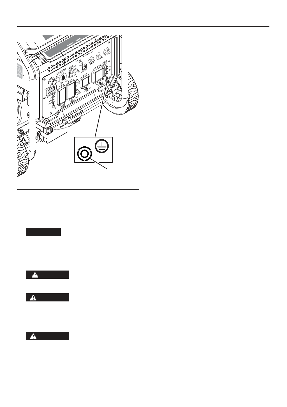
GROUNDING
See Figure 3.
WARNING
erly ground the generator can result in electric shock.
NOTICE
extension cords, tools, and appliances, or doubleinsulated tools and appliances.
The generator neutral is bonded to the frame. There is a
permanent conductor between the generator (stator wire)
and the frame. If this generator will be used only with cord
and plug equipment connected to the receptacles mounted
on the generator, National Electric Code does not require
that the unit be grounded. However, other methods of using
the generator may require grounding to reduce the risk of
shock or electrocution.
Before using the ground terminal, consult a qualied electrician, electrical inspector, or local agency having jurisdiction
for local codes or ordinances that apply to the intended use
of the generator.
Shock hazard. Failure to prop-
Only use grounded 3-prong
DISCONNECTING THE BONDED NEUTRAL
See Figure 3.
The bonded neutral should only be removed under specic
circumstances. Consult a qualied electrician to determine
if circumstances require disconnecting the bonded neutral.
l Remove the alternator cover.
6 | English
Page 7
SAFETY
7600/10000
FIG. 3
A
A - Ground terminal
l Remove the white bonded jumper wire from the ground
bolt and unmarked terminal connection. Reinstall the
bolts and tighten securely.
l Keep the bonded jumper wire in a secure location so that
the generator can be returned to the original conguration.
NOTICE
ED” Label over the “NEUTRAL BONDED TO FRAME”
label on the front of the control panel.
Apply a new “NEUTRAL UNBOND-
SAFETY PRECAUTIONS FOR GASOLINE
AND GASOLINE VAPOR
DANGER
Gasoline is highly explosive and ammable and can
cause severe burns or death.
WARNING
loosen or remove the fuel cap while the generator is
running. Turn the unit off and allow it to cool for at
least ve minutes before adding gasoline. Loosen the
fuel cap slowly.
WARNING
attempt to extinguish the ame if the fuel tank valve
is in the ON position. Introducing an extinguisher to
a generator with an open fuel switch could create an
explosion hazard.
Fire and explosion hazard.
Fire and Burn Hazard. NEVER
In case of a gasoline re, do not
l Fire Hazard. Gasoline is highly ammable. Handle with
care.
l Never use gasoline as a cleaning agent.
l Gasoline is a skin irritant and needs to be cleaned up
immediately if it comes in contact with the skin.
l Do not store gasoline near furnaces, water heaters, or
any other appliances that produce heat or have automatic
ignitions.
l Keep gasoline away from sparks, open ames, pilot
lights, heat, and other sources of ignition.
l Store any containers containing gasoline in a well-ven-
tilated area, away from any combustibles or source of
ignition.
l ALWAYS store gasoline in a container approved for gas-
oline. Unapproved containers can break or deteriorate
allowing gasoline or gasoline vapors to escape which
can create a serious hazard.
l Gasoline has a distinctive odor, this will help detect po-
tential leaks quickly.
l Gas vapors can cause a re if ignited.
l Do not smoke when handling fuel, adding fuel to the
generator, or emptying the gas tank.
l Wear eye protection while refueling.
l Before adding fuel to the generator, turn the unit off and
allow it to cool a minimum of ve minutes. If necessary,
move the unit to level ground.
l Do not remove the fuel tank cap when the generator is
running.
l Loosen the fuel cap slowly to safely release pressure,
keep gasoline from escaping around the cap, and to
avoid the heat from the mufer igniting fuel vapors.
l NEVER ll the generator’s gasoline tank beyond the
maximum ll ring on the fuel screen. Keeping gasoline
levels at or below the ll ring will allow for fuel expansion.
Overlling the fuel tank can result in a sudden overow of
gasoline and result in spilled gasoline coming in contact
with HOT surfaces.
l Spilled fuel can ignite. Wipe up spills immediately and
allow area to dry before operating the generator. NEVER
attempt to burn off spilled fuel.
l Securely tighten the fuel cap after adding gasoline.
l Do not cover the fuel cap while the generator is in oper-
ation. Covering the cap may cause the engine to fail or
damage the product.
l Drain fuel before storing the unit. Store the unit and
the fuel separately in well-ventilated areas away from
sparks, open ames, pilot lights, heat, and other sources
of ignition.
l Turn the unit off and allow it to cool a minimum of 30
minutes before draining fuel.
English | 7
Page 8
SAFETY
7600/10000
IMPORTANT INFORMATION FOR THE
COSENSOR
The CO Sensor monitors for the accumulation of poisonous
carbon monoxide gas around the generator when the engine is running. If increasing levels of CO gas are detected,
the CO Sensor automatically shuts down the engine.
The CO Sensor will also detect the accumulation of carbon
monoxide from other fuel burning sources used in the area
of operation. For example, if the exhaust of fuel burning
tools is pointed at a CO Sensor-equipped generator, a
shut-off may be initiated due to rising CO levels. This is not
an error. Hazardous carbon monoxide has been detected.
Move and redirect any additional fuel burning sources
to dissipate carbon monoxide away from personnel and
occupied buildings.
NOTE: Remote start-equipped generators must be restarted with the START/STOP button on the control panel after
an automatic shut-down occurs.
Generators are intended to be used outdoors, far from
occupied buildings and the exhaust pointed away from
personnel and buildings. If misused and operated in a
location that results in the accumulation of CO, like in a
partially enclosed area, the CO Sensor shuts off the engine
and the RED indicator light will ash notiying the user that
there are unsafe levels of carbon monoxide.
If the generator shuts off and the RED indicator light ashes,
leave the area immediately. Wait for the carbon monoxide
to dissipate and the RED indicator light to turn off before
returning to the affected area. Once it is safe to return, read
the Action Label for further steps to take. The CO Sensor
DOES NOT replace carbon monoxide alarms. Install battery-powered carbon monoxide alarm(s) in your home.
WARNING
with a ashing RED light in the CO Sensor portion
of the control panel is an indication that the generator
was improperly located which allowed carbon monoxide to accumulate to unsafe levels. If you start to
feel sick, dizzy, weak, or carbon monoxide detectors
in your home indicate an alarm, get to fresh air immediately. Call emergency services. You may have
carbon monoxide poisoning.
Automatic shutoff accompanied
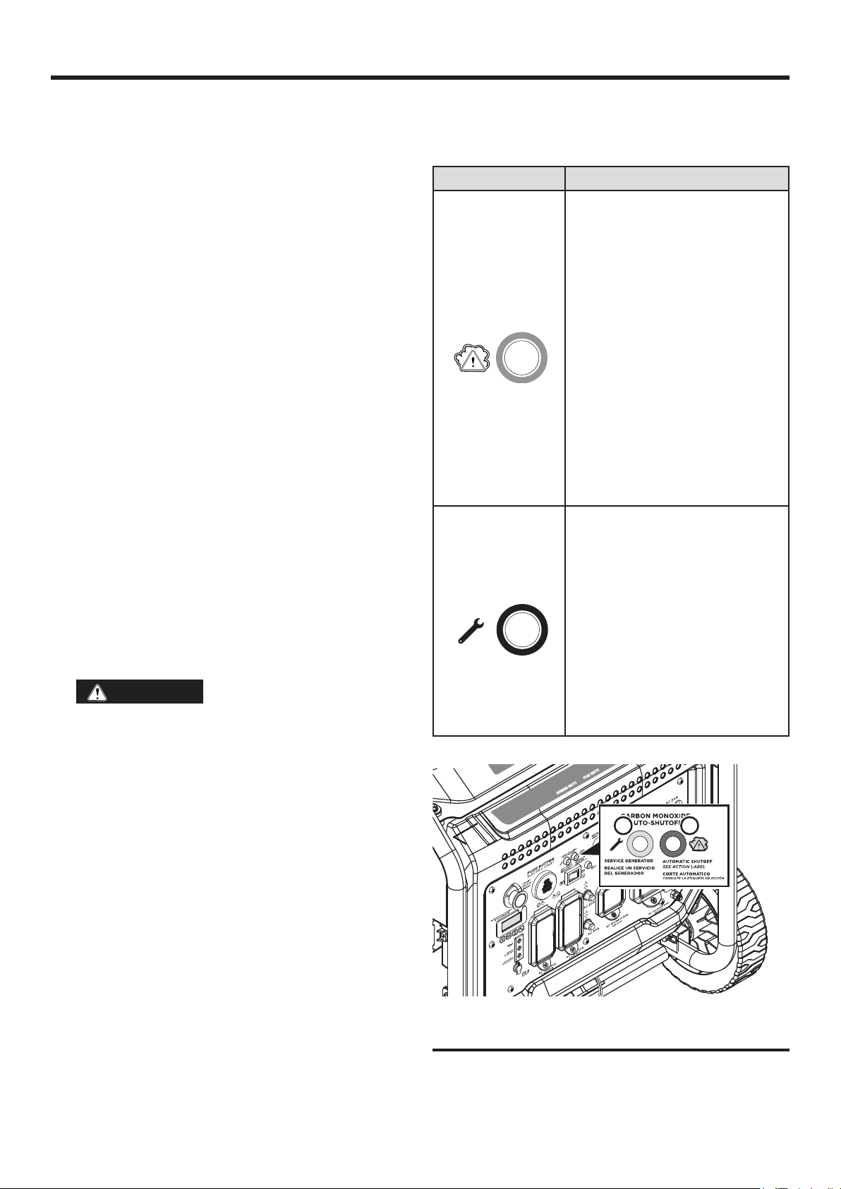
UNDERSTANDING THE CO SENSOR’S
INDICATOR LIGHTS
See Figure 4.
COLOR DESCRIPTION
Unsafe levels of carbon monoxide
accumulated around the generator.
After shut-off, the RED indicator
light in the CO Sensor area of the
control panel will ash to provide
notication that the generator was
shut-off due to carbon monoxide
RED
YELLOW
levels rising above a safe threshold.
The RED light will ash for at least
ve minutes after a CO shut-off.
When it is safe to do so, move the
generator to an open, outdoor area
far away from occupied spaces
with exhaust pointed away. Once
relocated to a safe area and the
red light is off, the generator can
be restarted. Introduce fresh air
and ventilate the area where the
generator had shut down.
A CO sensor system fault occurred.
When a system fault occurs, the
generator is automatically shut
down and the YELLOW indicator
light in the CO auto-shutoff area of
the control panel will ash to provide
notication that a fault has occurred.
The YELLOW light will ash for at
least ve minutes after a fault. The
generator can be restarted but may
continue to shutoff. A CO sensor
fault can only be diagnosed and
repaired by an authorized Westinghouse service center.
FIG. 4
A B
8 | English
A - Service generator LED
B - Automatic shutoff LED
Page 9
SAFETY
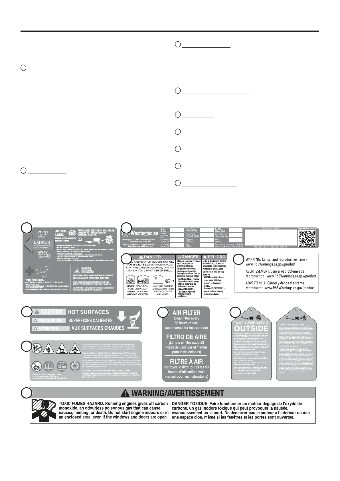
SAFETY LABELS AND DECALS
The following information is on your generator’s labels
and decals.
1
Action Label
If unsafe levels of carbon monoxide accumulate around
the generator, automatic shutoff will occur. If the unit shuts
off, leave the area immediately. When it is safe to return,
do the following:
l Move the generator to an open, outdoor area.
l Point exhaust away.
l Don’t run generator in enclosed areas (e.g. not in house
or garage).
l Move to fresh air.
l Get medical help if sick, dizzy or weak.
l WARNING – Tampering with carbon monoxide sensor
could result in hazardous condition.
2
Specications
(See page 3)
3
Carbon Monoxide
l Using a generator indoors CAN KILL YOU IN MINUTES.
Generator exhaust contains carbon monoxide. This is a
poison you cannot see or smell.
l NEVER use inside a home or a garage, EVEN IF doors
and windows are open.
4
California Proposition 65
Cancer and reproductive harm -
www.P65Warnings.ca.gov/product
5
Hot Surface
Do not touch.
6
Safety Symbols
(See page 4)
7
Air Filter
Clean lter every 50 hours of use!
8
Take Generator Outside
Generators are intended to be used outdoors.
9
Toxic Fumes Hazard
Running engines give off carbon monoxide, an odorless
poisonous gas that can cause nausea, fainting, or death.
Do not start engine indoors or in an enclosed area, even
if the windows and doors are open.
1 2
5
6
9
3
4
7 8
English | 9
Page 10
SAFETY
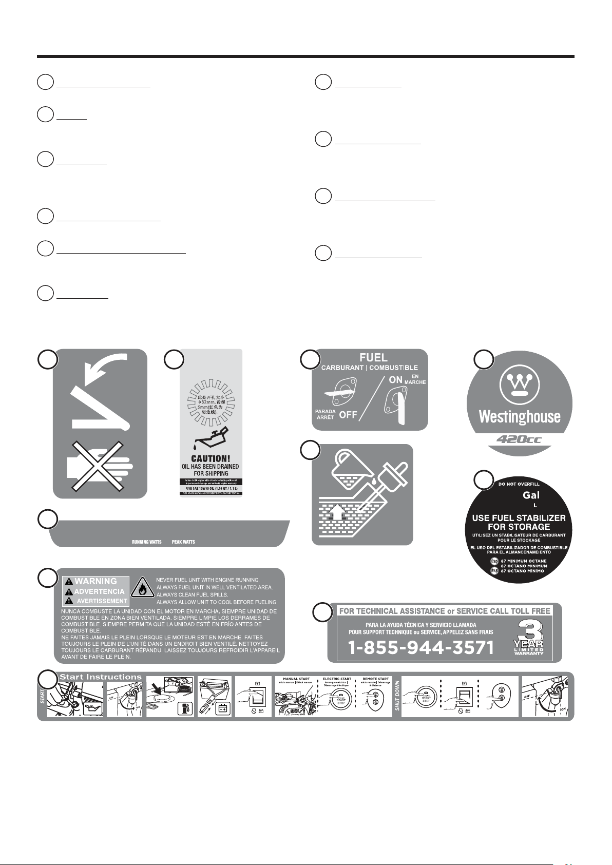
10
Pinch Point Hazard
Keep ngers and hands away from pinch point.
11
No Oil
Oil has been drained from the unit for shipping. Add oil
before attempting to operate the unit.
12
Fuel Valve
Turn the fuel valve to the on position when starting the
unit. Turn the fuel valve to the off position when the unit
is not in use.
13
Engine Displacement
This unit has a 420 cc engine.
14
Running Watts/Peak Watts
The Westinghouse Generator produces 10,000 peak watts
and 7,600 running watts
15
Adding Oil
Add engine oil until the oil level is within safe operating
range.
10
11 12 13
16
Fuel Capacity
This generator has a 5.3 gallon fuel tank. ALWAYS use
CLEAN, FRESH, unleaded gasoline (87 – 93 octane) in this
unit. Do not use E15 or E85 fuel in this product.
17
Risk of Explosion
Never fuel unit with engine running. Always fuel unit in well
ventilated area. Always clean fuel spills. Always allow unit
to cool before fueling.
18
EZ Start Instructions
Refer to the “EZ Start Instructions” label and the instructions
in the Operations section when starting and stopping the
generator.
19
Customer Service
For technical assistance or service call toll free at
1-855-944-9571
14
17
18
此处 开孔大 小
φ32mm,齿深
5mm(红 色为
7600/10000
切边 线).
15
19
16
5.3
20
10 | English
Page 11
ELECTRICAL
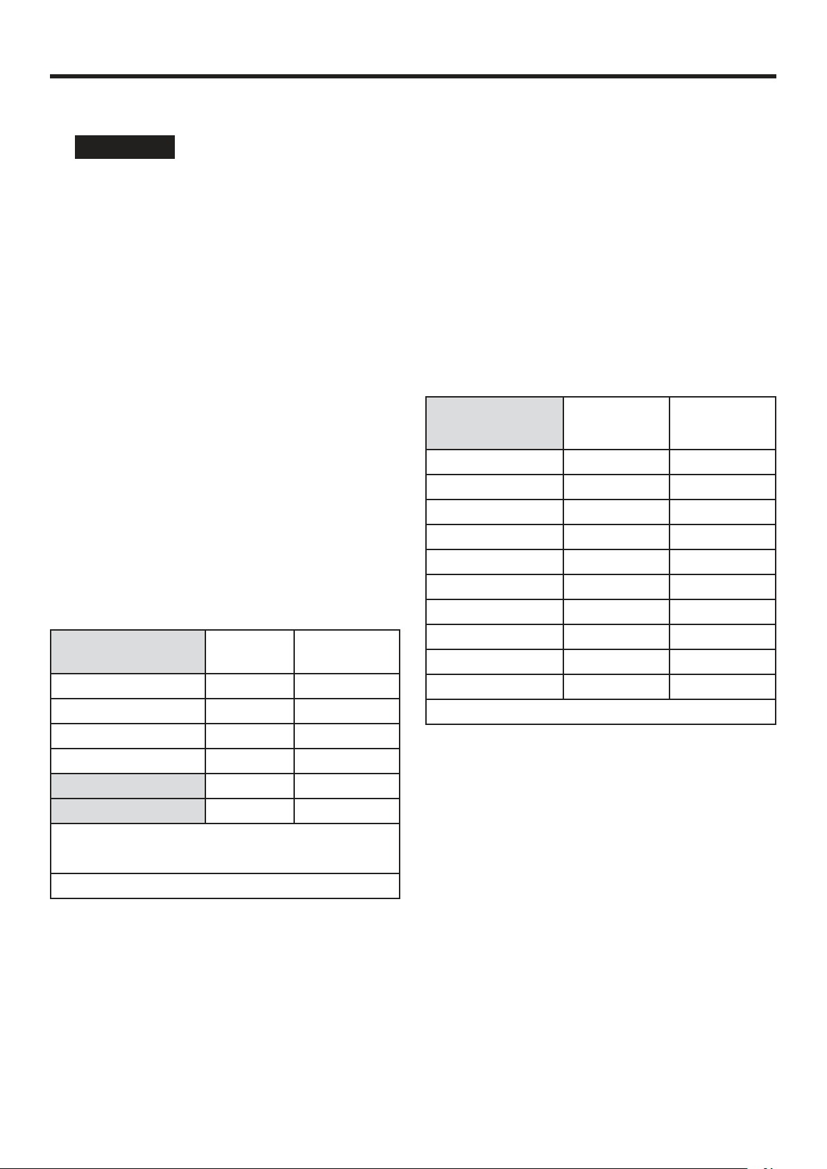
GENERATOR CAPACITY
NOTICE
pacity. Exceeding the generator’s wattage/amperage
capacity can damage the generator and/or electrical
devices connected to it.
Review the Specications for this generator and record
the running (continuous) and peak (starting) watts. In
general the higher the wattage, the more devices can be
powered at the same time. The total power requirements
of all connected devices must be considered.
To determine power requirements:
l Choose the devices you want to power simultaneously.
l Record and total the running (continuous) watts of each
device. The generator must continuously produce this
amount of wattage to keep the devices running.
l Record the peak (starting) watts for each device. This is
the momentary surge of power required to start electric
motors in some tools and appliances.
l Select the device with the highest peak (starting) wattage.
Add the peak (starting) watts for that device to the total
running (continuous) watts for all the connected devices
to determine the total peak wattage requirement for the
generator.
NOTE: Total peak wattage requirement assumes inter-
mittent starting of devices. Adjust estimate if devices
reach peak wattage at the same time.
Do not overload the generator’s ca-
MANAGING GENERATOR POWER
To extend the service life of the generator, use caution
when adding electrical loads. Disconnect all loads before
starting the generator. The safest way to manage generator
power is to add loads sequentially by doing the following:
l Remove all loads and start the generator as described
later in this manual.
l Connect and start the largest device or appliance.
l Allow the generator output to stabilize. Once stable,
the engine should run smoothly and the device should
function properly.
l Connect and start the next largest device or appliance.
l Allow the generator output to stabilize.
l Repeat this process for each additional load.
WATTAGE REFERENCE
Tool or appliance
AM/FM Radio 100 --Box Fan 100 --Television 500 --RV Air Conditioner 700 1500
Coffee Maker 1000 ---
Microwave 1000 ---
Running
Watts*
Additional
PeakWatts*
Example:
Tool or appliance
RV Air Conditioner 700 1500
Refrigerator/Freezer 700 2200
Microwave 1000 ---
Television (27 in.) 500 ---
Total Running Watts* 2900 ---
Highest Peak Watts* --- 2200
Total Running Watts 2900
Highest Peak Watts + 2200
Total Peak Wattage 5100
In this example, you would need a generator with at
least 2900 running (continuous) watts and 5100 peak
(starting) watts to power all the connected devices.
*Wattages listed are approximate. Verify actual wattage.
Running
Watts*
Additional
PeakWatts*
Refrigerator/Freezer 700 2200
Sump Pump ½ HP 1050 2150
Air Compressor 1400 3600
Table Saw (10 in.) 2000 2000
* Wattages listed are approximate. Verify actual wattage.
English | 11
Page 12
ELECTRICAL
EXTENSION CORDS
WARNING
cords running directly into the home increase the risk
of carbon monoxide poisoning through any openings.
If an extension cord running directly into your home is
used to power indoor items, there is a risk of carbon
monoxide poisoning to people inside the home. Always use battery-powered carbon monoxide detector
(s) that meet current UL 2034 safety standards when
running the generator. Regularly check the detector(s) battery.
WARNING
erating the generator with extension cords, make sure
the generator is located in an open, outdoor area, at
least 20 ft. (6 m.) from occupied spaces with exhaust
pointed away.
WARNING
Never use worn or damaged extension cords. Damaged or overloaded extension cords could overheat,
arc, and burn resulting in death or serious injury.
Before connecting an AC appliance or power cord to the
generator:
l Use grounded 3-prong extension cords, tools, and ap-
pliances, or double-insulated tools and appliances.
l Make sure the tool or appliance is in good working order.
Faulty appliances or power cords can create a potential
for electric shock.
Asphyxiation hazard. Extension
Asphyxiation hazard. When op-
Fire and electrocution hazard.
l Make sure the electrical rating of the tool or appliance
does not exceed the rated power of the generator or the
receptacle being used.
NOTICE
Overloading the generator’s wattage and/or amperage capacity could damage connected devices and
critical generator components.
Do not exceed the unit’s capacity.
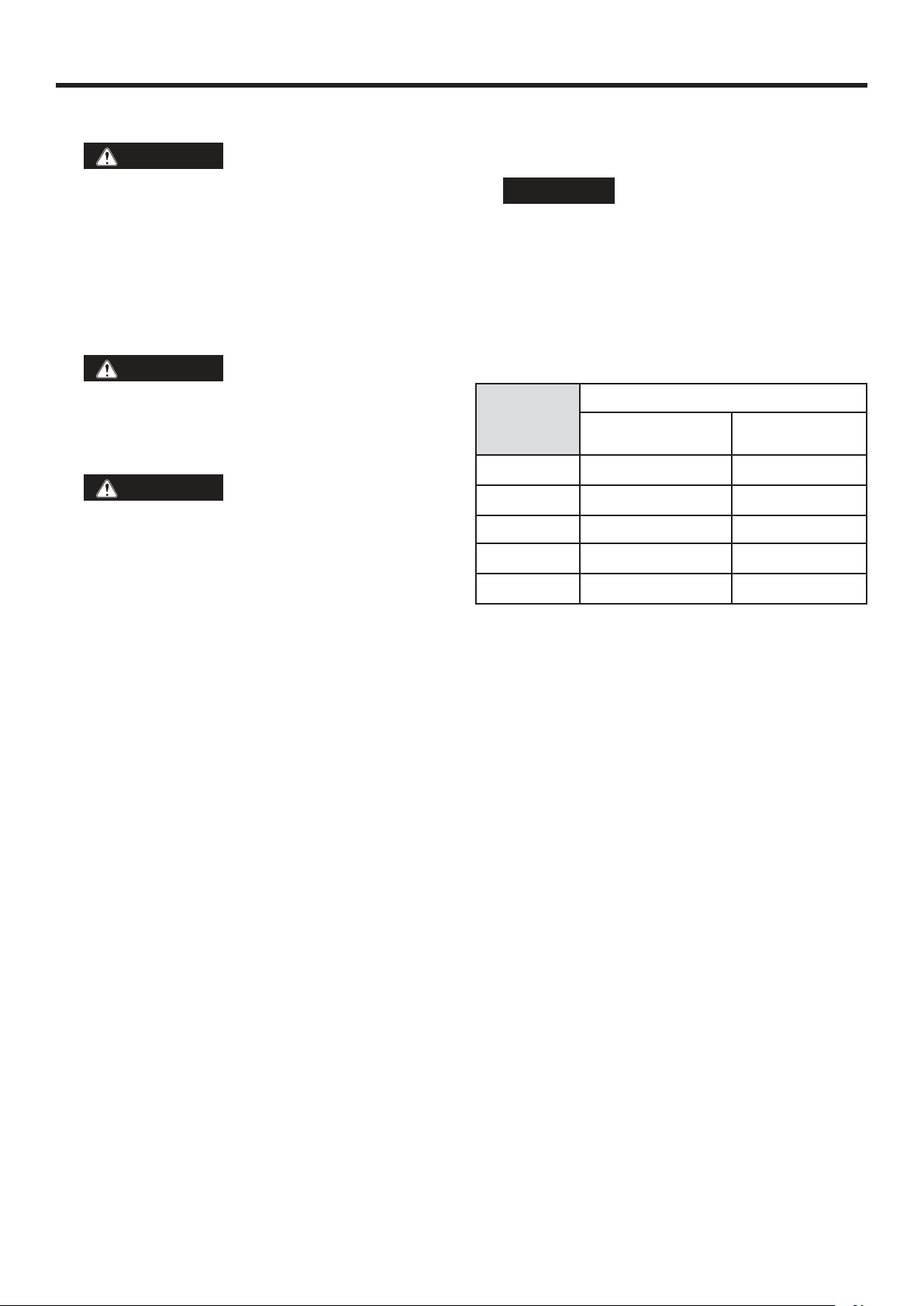
EXTENSION CORD SIZING
Make sure your extension cord can carry the required load.
Cables that are too small may cause a voltage drop that
can cause the cord to overheat or cause property damage.
Refer to the chart below.
TOTAL
AMPERAGE
Up to 10A #12 Wire #8 Wire
Up to 15A #10 Wire #8 Wire
Up to 20A #10 Wire #6 Wire
Up to 30A #8 Wire #6 Wire
Up to 35A #6 Wire #6 Wire
MINIMUM GAUGE, OUTDOOR RATED
Up to 50 ft. (15 m)
Up to 100 ft.
(30 m)
12 | English
Page 13
COMPONENTS
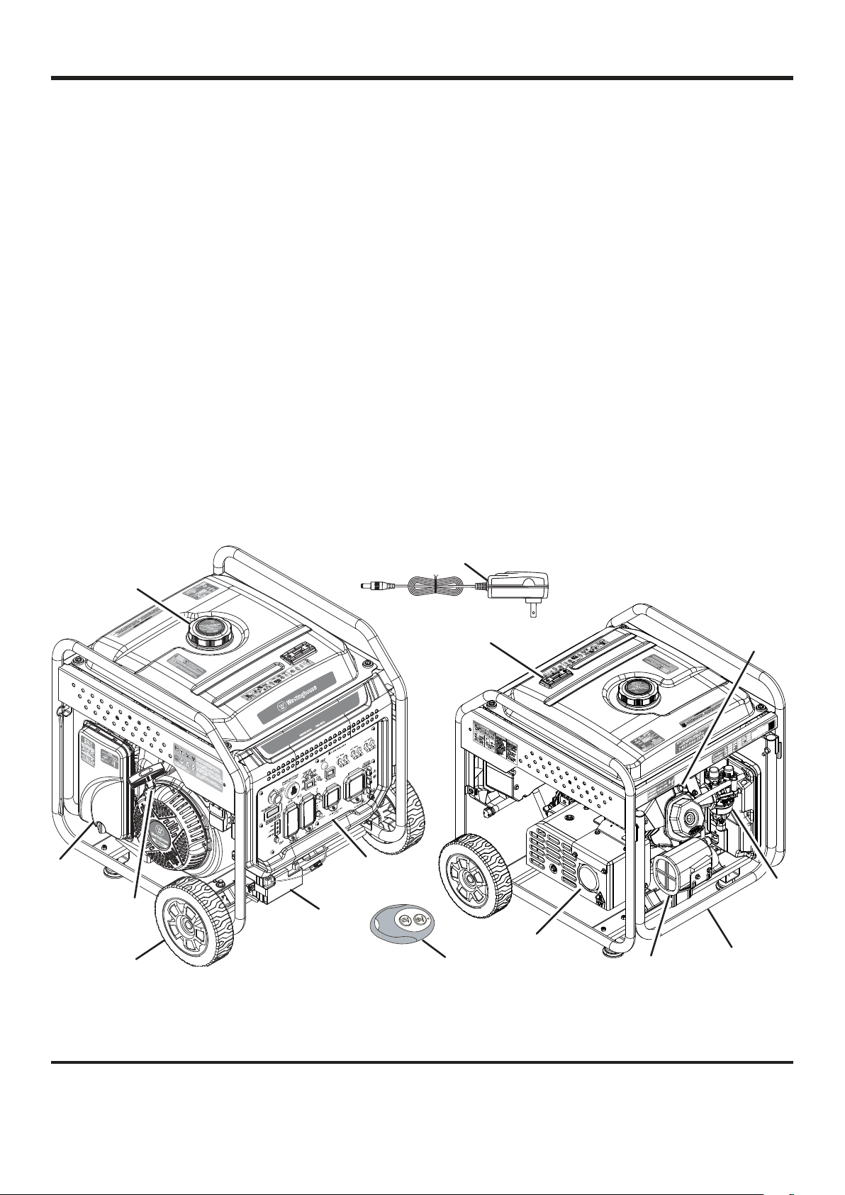
UNDERSTANDING YOUR GENERATOR
See Figures 5 - 6.
To reduce the risk of injury and product failure, read and
understand the information in this user’s manual as well as
the information on the product labeling.
120 VOLT AC, 20 AMP RECEPTACLES
This unit has two single phase, 60 Hz receptacles capable
of carrying a maximum of 20 amps.
120/240-VOLT AC RECEPTACLES
(30 AND 50 AMP)
Each receptacle can supply either 120V or 240V.
NOTE: The L14-30R receptacle can supply up to 30 amps
and the L14-50R receptacle can supply up to 50amps.
BATTERY CHARGING PORT
Insert the plug of the included AC charger to charge the
battery.
BATTERY INDICATOR
Light will remain illuminated while battery power is available.
BATTERY SWITCH
Enables or disables electric start. The battery switch must
be in the ON positoin to use remote start.
CIRCUIT BREAKERS
The circuit breakers protect individual circuits from electrical
overload.
CO SENSOR INDICATOR LIGHTS
The CO Sensor monitors for the accumulation of poisonous
carbon monoxide gas. If increasing levels of CO gas are detected, the CO Sensor automatically shuts down the engine.
DATA CENTER
Displays voltage, frequency, total hour meter, and run/
maintenance timer.
ECO MODE SWITCH
Eco mode minimizes fuel consumption and noise by adjusting the engine RPM to the minimum required for the
current load.
FIG. 5
A
J
I
K
A - Fuel cap
B - Fuel gauge
C - Battery
D - Muffler/spark arrestor
E - Carbon canister
N
20
5.3
00/10000
76
B
5.3
20
G
H
F
C
D
L
F - Carburetor/choke
G - Spark plug
H - Control panel
I - Recoil handle
J - Air filter cover
M
K - Wheel
L - Transport handle
M - Key fob
N - Charger
E
English | 13
Page 14
COMPONENTS
ENGINE START/STOP BUTTON
Push once to automatically start the engine. Push again to
stop the engine.
FUEL TANK
The generator has a fuel tank with a capacity of 20liters.
NOTE: The fuel gauge on top of the tank shows the approximate fuel level.
GROUND TERMINALS
The ground terminals are used to externally ground the
generator.
LOW OIL LED
Indicates low oil level. When the oil level in the crankcase
falls below the safe operating limit, the low oil level indicator
will illuminate and the generator will automatically shut off
the engine.
MUFFLER AND SPARK ARRESTOR
The spark arrestor prevents sparks from exiting the mufer.
It must be removed for servicing.
NOTICE
that prevents sparks from exiting the mufer and creating a re hazard. In certain locations a spark arrestor
may be required by law. It is the operator’s responsibility to know and follow all local laws and regulations
related to re prevention requirements.
The spark arrestor is a safety device
OIL DIPSTICK
Unscrew the oil dipstick to check oil levels and add oil when
needed.
OUTPUT READY LED
Illuminates when the generator is operating normally. Indicates the generator is producing electrical power at the
receptacles.
OVERLOAD LED
Indicates that the generator is overloaded.
OVERLOAD RESET
The generator will automatically switch OFF all AC output
to protect the generator if overloaded or if there is a short
circuit in a connected appliance.
PARALLEL OPERATION OUTLETS
A compatible Westinghouse generator can be connected
for additional power output.
RECOIL HANDLE
Use the recoil handle (along with the fuel valve and choke)
to manually start the generator.
REMOTE START
Use the key fob to start the generator remotely.
SMART SWITCH OUTLET
The smart switch outlet allows you to connect a Westinghouse ST Switch (sold separately) to the generator.
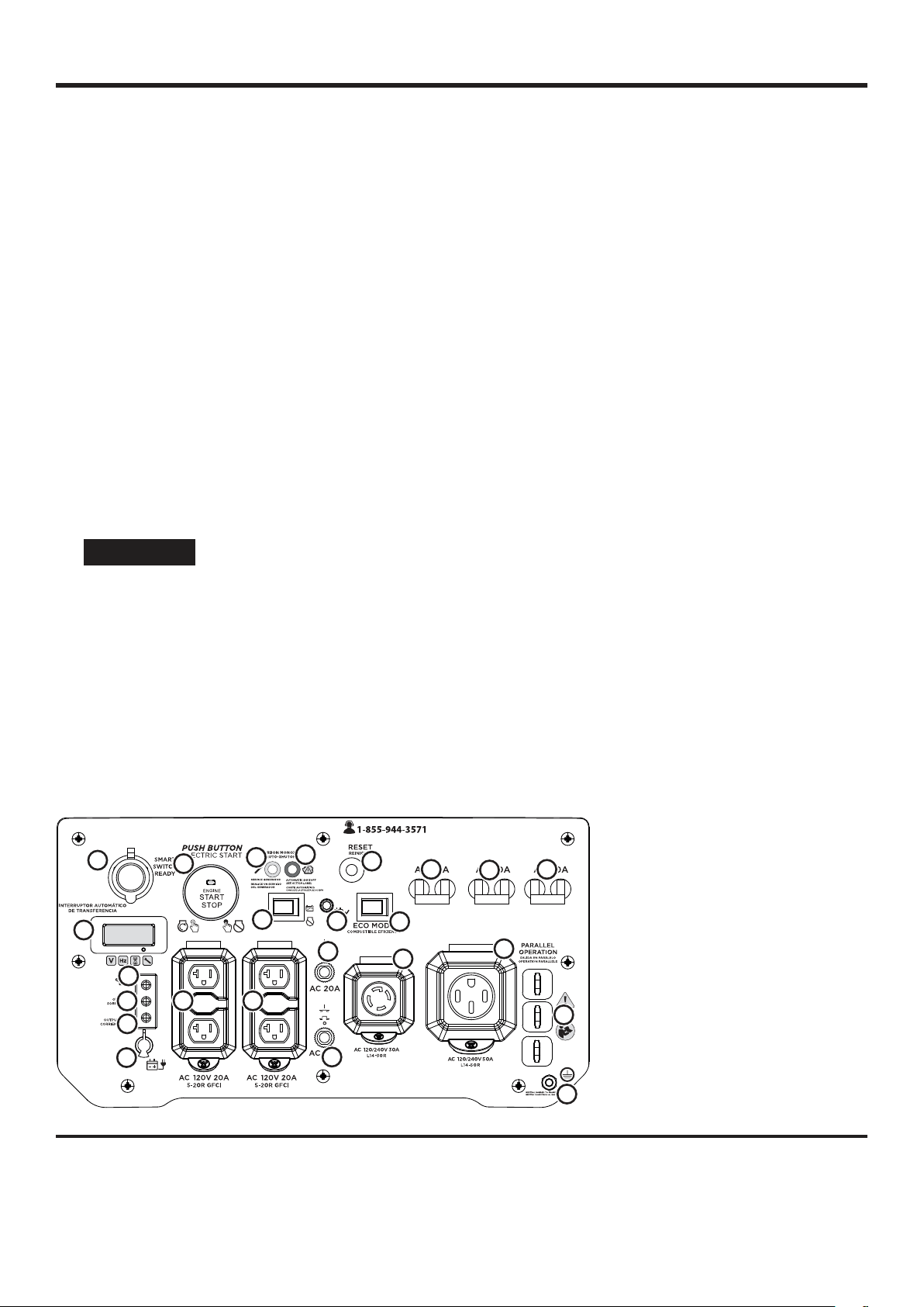
FIG. 6
A
M
A - Smart switch outlet
B - Engine start/stop button
C - Service generator LED
D - Automatic shutoff LED
B
F
G
H
J
K
C
K
D
U
T
E
L
L
N
P
Q
N
O
R
S
E - Battery indicator
F - Low oil LED
G - Overload LED
H - Output ready LED
I - Ground terminal
J - Battery charging port
K - 120 volt AC 20 amp GFCI receptacles
L - 20 amp circuit breaker
M - Data center
N - 32 amp circuit breaker
O - 50 amp circuit breaker
P - ECO mode switch
Q - 120/240 volt AC 30 amp receptacle
R - 120/240 volt AC 50 amp receptacle
S - Parallel operation outlets
T - Reset button
I
U - Battery switch
14 | English
Page 15
ASSEMBLY
WARNING
sistance when lifting the generator. Never attempt to
lift the unit by the handle. Hold the unit by the frame
and use proper lifting techniques to reduce the risk of
back injury.
Weight hazard. Always have as-
REMOVING CARTON CONTENTS
WARNING
Do not attempt to operate this product if any items
in the INCLUDED LIST are already assembled when
you remove the carton contents. These items are not
assembled by the manufacturer and should require
customer assembly. Using an improperly assembled
product can be hazardous and could result in serious
personal injury.
l Carefully cut down the sides of the packaging and remove
the carton contents.
l Inspect the carton contents. Verify that all the items in
the INCLUDED LIST are present and undamaged.
l Recycle or dispose of the packaging materials properly.
This product requires assembly.
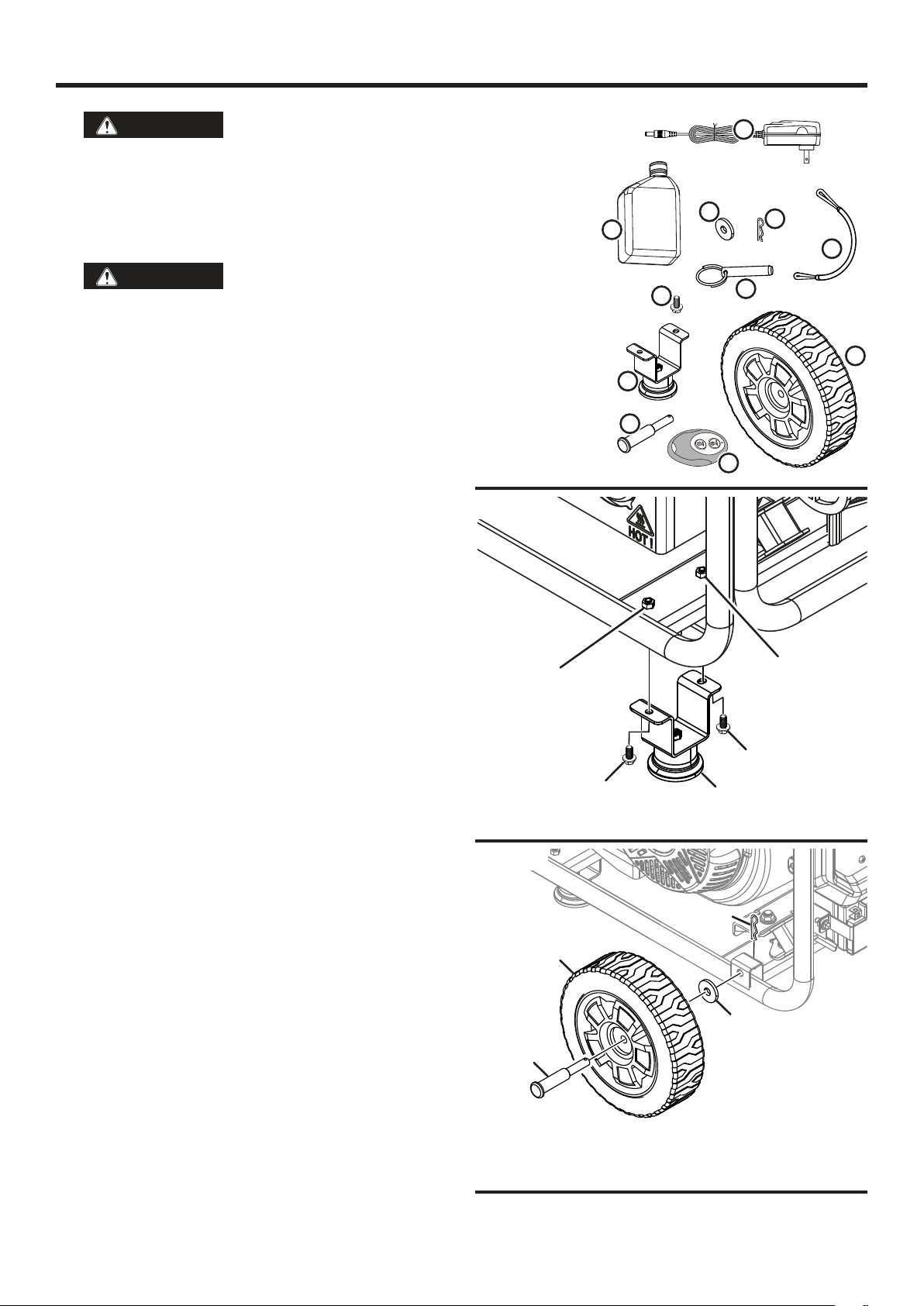
INCLUDED LIST
See Figure 7.
Generator, Wheels, Axles, Washers, Hitch Pins, Handle
Lock Pin, Lanyard, Bolts, Feet, Key Fob, Charger, Engine
Oil (SAE 10W 30), Funnel, Spark Plug Socket Wrench,
Quick Start Guide, User Manual
If any parts are missing, contact our service team at
[email protected] or call 1-855-944-3571.
FIG. 7
A - Wheel
B - Axle
C - Washer
D - Hitch pin
E - Handle lock pin
F - Lanyard
G - Charger
H - Bolt
I - Foot
J - Oil bottle
K - Key fob
FIG. 8
C
G
C
J
H
I
B
D
F
E
A
K
C
INSTALLING THE FEET
See Figure 8.
l Place the generator on a at surface.
l Lift the handle side of the generator high enough to gain
access to the crossbar on the bottom of the frame.
l Place props beneath the generator to serve as a tempo-
rary support.
l Locate the feet and bolts.
l Align the holes in a foot with the holes in the crossbar.
l Insert bolts through the holes in the foot.
l Thread the bolts into the nuts welded onto the crossbar
and tighten securely. Do not over tighten.
l Repeat these steps to install second foot.
INSTALLING THE WHEELS
See Figure 9.
l Place the generator on a at surface.
l Lift the control panel side of the generator high enough
to gain access to the bottom of the frame.
l Place props beneath the generator to serve as a tempo-
rary support.
l Locate the axles, wheels, washers, and hitch pins.
A - Foot
B - Bolt
C - Nut
FIG. 9
A
A - Axle
B - Wheel
C - Washer
D - Hitch pin
B
B
B
A
D
C
English | 15
Page 16
ASSEMBLY
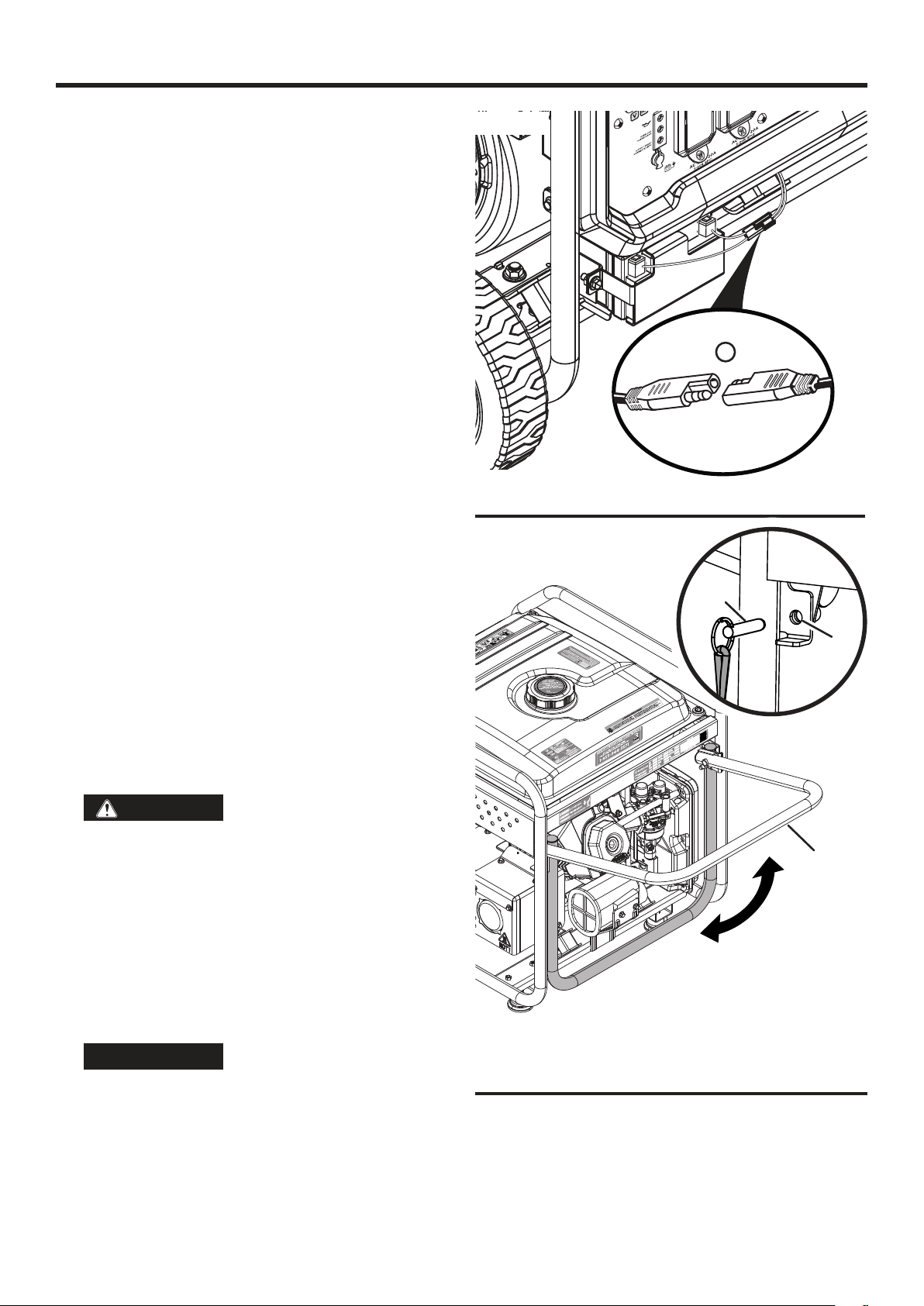
l Insert a bolt through the middle of a wheel, washer, and
the frame as shown.
l Push a hitch pin into the axle until the center of the pin
rests against the top of the axle.
l Repeat these steps to install second wheel.
CONNECTING THE BATTERY
See Figure 10.
A quick-connect battery cable is pre-installed on the battery.
Remove the cable tie securing the plugs then push rmly
to connect them.
NOTE: The generator is equipped with a battery charging
feature. Once the engine is running, a small charge will
slowly recharge the battery.
LOCKING/RELEASING THE HANDLE
See Figure 11.
A quick-connect battery cable is pre-installed on the battery.
Remove the cable tie securing the plugs then push rmly
to connect them.
NOTE: The generator is equipped with a battery charging
feature. Once the engine is running, a small charge will
slowly recharge the battery.
l Locate the handle lock pin and lanyard.
l Attach the lanyard to the lock pin and frame.
l To lock the handle in the raised position, raise the
handle and insert the lock pin through the holes in the
handle and frame.
l With handle locked in the raised position, the generator
can safely be rolled from one position to another. For
information regarding transporting the unit in a vehicle,
refer to the Transporting section in Operation.
l To release and lower the handle, remove the lock pin
and guide the handle to the down position.
FIG. 10
A - Quick-connect battery cable
FIG. 11
5.3
20
A
B
C
WARNING
uct unless instructed to so in this manual or by the
manufacturer. Do not use attachments or accessories
that are not recommended for use with this product.
Making unauthorized modications and using incompatible accessories can damage the unit and void
your warranty.
Do not alter or modify this prod-
OVERVIEW
This portable generator can provide power to a wide range
of items including household appliances, job-site tools,
camping equipment, tailgating essentials, and much more.
NOTICE
SHIPPED WITHOUT OIL. Do not attempt to crank or
start engine before it has been properly serviced with
recommended oil. Failure to add engine oil before
starting will result in serious engine damage that is
not covered under warranty.
THIS GENERATOR HAS BEEN
16 | English
A
A - Transport handle
B - Handle lock pin
C - Hole
Page 17

OPERATION
DANGER
high levels of carbon monoxide (CO), an invisible,
odorless, and extremely poisonous gas. If you smell
exhaust fumes, you are breathing carbon monoxide.
But, even if you do not smell exhaust fumes you may
be inhaling CO.
ONLY operate generators outside, in a well-ventilated
area. NEVER operate generators indoors, doing so
CAN KILL YOU IN MINUTES.
• Correct Use – ONLY use generators outside and
downwind, far away from windows, doors and vents.
ALWAYS direct exhaust away from occupied spaces. ALWAY S install battery-powered carbon monoxide detectors or plug-in carbon monoxide detectors
with battery back-up in living areas. See Figure 1.
• Incorrect Use – NEVER use a generator in your
home, garage, basement, attic, crawl space or any
other fully or partially enclosed area. Areas such as
these can allow dangerous levels of carbon monoxide to accumulate. An open door or a running
fan WILL NOT provide adequate ventilation. See
Figure2.
If you start feeling dizzy, weak, or sick while using the
generator, move to fresh air IMMEDIATELY. Contact
a doctor. You may be experiencing carbon monoxide
poisoning.
WARNING
uct unless instructed to so in this manual or by the
manufacturer. Do not use attachments or accessories
that are not recommended for use with this product.
Making unauthorized modications and using incompatible accessories can damage the unit and void
your warranty.
NOTICE
tional Electric Code may require the generator to be
grounded to an approved earth. Consult with a qual-
ied electrician to determine grounding requirements
before operation.
WARNING
oil or gasoline. Wear protective clothing and equipment. Wash all exposed skin with soap and water.
Prolonged skin contact with gasoline or engine oil
may cause severe skin irritation and other adverse
reactions.
NOTICE
product prior to each use. Look for loose bolts, uid
leaks, and other signs of wear. Replace all damaged
items.
Generator exhaust contains
Do not alter or modify this prod-
In certain circumstances, the Na-
Avoid skin contact with engine
Check the physical condition of the
NOTICE
properly installed before adding fuel or oil.
Make sure the wheels and feet are
KNOW HOW TO SAFELY LOCATE AND
OPERATE YOUR GENERATOR
DANGER
generator in a well-ventilated area. DO NOT place the
generator near vents or intakes where exhaust fumes
could be drawn into occupied or conned spaces.
Carefully consider wind and air currents when positioning the generator.
WARNING
the generator in a location that is wet or damp. Never expose the generator to rain, snow, water spray,
or standing water while in use. Protect the generator
from all hazardous weather conditions. Moisture or
ice can cause a short circuit or other malfunction in
the electrical circuit. Using a generator or electrical
appliance in wet conditions, such as rain or snow, or
near a pool or sprinkler system, or when your hands
are wet, could result in electrocution.
WARNING
generator on a solid, level surface. Operating the generator on a surface with loose material such as sand
or grass clippings can cause debris to be ingested
by the generator that could block cooling vents or the
air intake system. Allow the generator to cool for 30
minutes before transport or storage.
l Read and understand all safety information before starting
the generator (see pages 4 - 10).
l NEVER use a generator in your home, garage, basement,
attic, crawl space or any other fully or partially enclosed
area. Areas such as these can allow dangerous levels
of carbon monoxide to accumulate. Carbon monoxide
(CO), an invisible, odorless, and extremely poisonous
gas CAN KILL YOU IN MINUTES.
l DO NOT operate the generator in the back of a SUV,
camper, trailer, truck bed (regular, at, or otherwise), under
stairs, next to walls or buildings, or in any other location
that will not allow for adequate cooling of the generator
and/or the mufer. Operating the generator in enclosed
or partially enclosed areas will allow dangerous levels
of CO to accumulate.
l DO NOT contain generators during operation.
l Only use OUTSIDE and far away from windows, doors,
and vents as recommended by the US Department of
Health and Human Services Centers for Disease Control
and Prevention. Your specic home and/or wind conditions
may require additional distance.
Asphyxiation hazard. Place the
Electrocution hazard. Never use
Fire hazard. Only operate the
English | 17
Page 18
OPERATION
l Do not operate the generator on an incline. The unit
should always be placed on a at, stable surface with a
slope no greater than 4°
l The generator should be on a at, level surface at all
times (even while not in operation).
l The generator must have at least 5 ft. (1.5 m) of clearance
from all combustible material.
KNOW THE REGULATIONS FOR THE USE
OF PORTABLE GENERATORS
Consider where and how you intend to use your generator,
and familiarize yourself with any local, state, or federal ordinances concerning your intended use. It may be necessary
to contact a qualied electrician or local governing agency
for a full list of requirements.
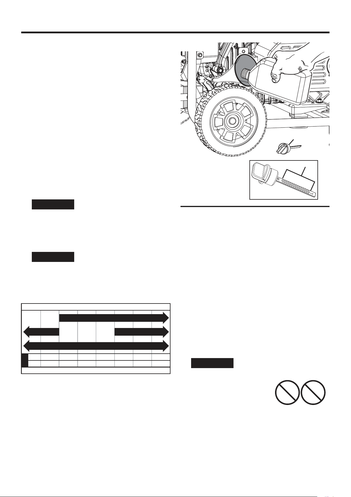
ADDING OIL/CHECKING OIL LEVEL
See Figure 12.
If your product has a separate engine manual, disregard the information in this section and follow the
instructions in the engine manual.
NOTICE
SHIPPED WITHOUT OIL. Do not attempt to crank or
start engine before it has been properly serviced with
recommended oil. Failure to add engine oil before
starting will result in serious engine damage that is
not covered under warranty.
NOTICE
approved oil types can cause severe engine damage
that is not covered under warranty.
The included, recommended oil type for typical use is
10W-30 engine oil. If running the generator in extreme
temperatures, refer to the following chart.
Recommended Engine Oil Type
-20 0 20 40 60 80 100 120
°F
-28.9
°C
-17.8 -6.7 4.4 15.6 26.7 37.8 48.9
NOTE: Check the engine oil level before each use or every
8 hours of operation.
l Turn the generator off and allow the engine to cool for
at least ve minutes.
l Place the generator on a level surface in a well-ventilated
area.
l Clean the area around the oil dipstick.
THIS GENERATOR HAS BEEN
Use of 2-stroke/cycle oil or other un-
10W-30
10W-405W-30
5W-30
Synthetic
Ambient Temperature
FIG. 12
A
B
A - Oil dipstick
B - Safe operating range
For initial oil ll:
l Slowly unscrew and remove the oil dipstick.
l Using the funnel, slowly pour the entire bottle of the
supplied engine oil into the oil ll hole. Stop frequently
to make sure you do not overll.
l Replace and tighten the oil dipstick.
To check oil level:
l Slowly unscrew and remove the oil dipstick.
l Clean the dipstick and re-seat it inside the oil ll hole.
Do not thread the dipstick.
l Remove the dipstick and verify that the oil level is within
safe operating range.
l If the oil level is low, add recommended engine oil in-
crementally and recheck until the level is within the safe
operating range.
l Replace the oil dipstick and hand-tighten.
GASOLINE REQUIREMENTS
NOTICE
product. Engine or equipment damage caused by
stale fuel or the use of unapproved fuels (such as E15 or
E85 ethanol blends) is not
covered by warranty. Only use
unleaded gasoline containing
up to 10% ethanol.
l ALWAYS use CLEAN, FRESH, unleaded gasoline
(87 – 93 octane) in this unit. NEVER use OLD, STALE,
or CONTAMINATED gasoline.
Do not use E15 or E85 fuel in this
E85 E15
18 | English
Page 19
OPERATION
l Up to 10% ethanol (gasohol) is acceptable (where avail-
able; non-ethanol fuel is recommended).
l DO NOT use E85 or E15.
l DO NOT use a gas oil mix.
l DO NOT modify the engine to run on alternate fuels.
USING FUEL STABILIZER
Adding a fuel stabilizer (not included) extends the usable
life of fuel and helps prevent deposits from forming that
can clog the fuel system. Follow the manufacturer’s instructions for use.
Always mix the correct amount of fuel stabilizer to gasoline in an approved gasoline container before fueling the
generator. Run the generator for ve minutes to allow the
stabilizer to treat the entire fuel system.
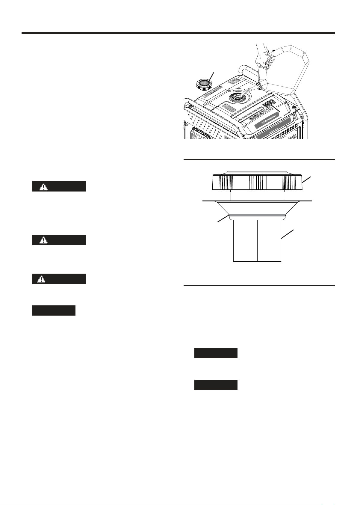
ADDING GASOLINE
See Figures 13 - 14.
DANGER
er remove the fuel cap or refuel the generator while
the engine is running. Do not smoke or create sparks
while fueling. Always turn the engine off and allow the
generator to cool for at least ve minutes before refueling.
Fire and explosion hazard. Nev-
FIG. 13
20
5.3
A - Fuel cap
B - Fuel gauge
FIG. 14
A
0
2
5.3
B
10000
00/
76
A
B
C
DANGER
Fire and explosion hazard. Do
not overll fuel tank. Fill only to the red maximum ll
ring on the fuel screen. Overlling may cause fuel to
spill onto engine causing a re or explosion hazard.
WARNING
Never use a gasoline container,
gasoline tank, or any other fuel item that is broken,
cut, torn or damaged.
NOTICE
Only ll the tank from an approved
gasoline container. Make sure the gasoline container
is internally clean and in good condition to prevent
fuel system contamination.
l Turn the generator off and allow the engine to cool for
at least ve minutes.
l Place the generator on a level surface in a well-ventilated
area. DO NOT fuel indoors.
l Clean area around fuel cap and remove the cap slowly.
l Slowly add the recommended fuel. Do not overll.
NOTE: The gasoline level should NOT be higher than
the red maximum ll ring on the fuel screen.
A - Fuel cap
B - Max fill line
C - Screen filter
NOTE: The fuel gauge on top of the tank shows the
approximate fuel level.
l Install the fuel cap. Tighten securely.
l Clean up any spilled fuel.
l Move at least 30 ft. away from refueling area before
restarting the engine.
NOTICE
Fuel can damage paint and plas-
tic. Use caution when lling the fuel tank. Damage
caused by spilled fuel is not covered under warranty.
NOTICE
Clean the fuel screen lter of debris
before and after each fueling. Remove the fuel screen
lter by slightly compressing it while removing it from
the fuel tank.
English | 19
Page 20
OPERATION
HIGH ALTITUDE OPERATION
Engine power is reduced the higher you operate above sea
level. Output will be reduced approximately 3.5% for every
1000 feet of increased altitude from sea level.
High altitude adjustment is required for operation at altitudes over 5,000 ft. (1524 m). Operation without this
adjustment will cause decreased performance, increased
fuel consumption, and increased emissions.
NOTICE
titudes below 2,000 ft. (762 m) with the high altitude
kit installed. Engine damage may occur.
High Altitude
Carburetor Kit
DO NOT operate the generator at al-
Part# 202801
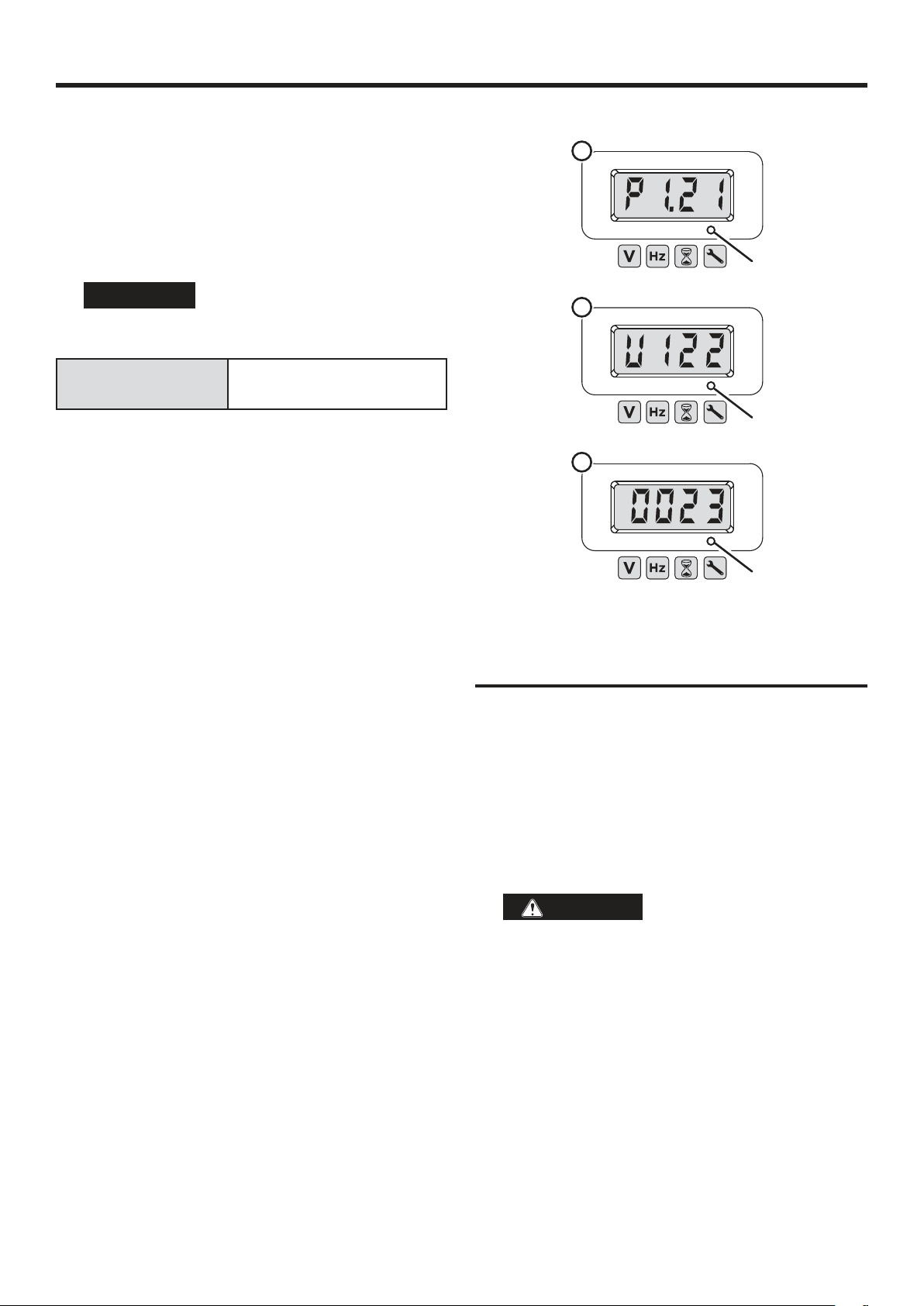
DATA CENTER
See Figure 15.
Push the mode button to cycle through the data display
modes.
Voltage: Displays current voltage output.
Frequency (Hz): Displays power output frequency in Hertz.
Lifetime Hours: Displays the lifetime run hours.
Run Time/Maintenance: Displays current run time. Resets
to zero when shut down. Maintenance reminder displayed
when required.
Maintenance Codes:
P25 – Change engine oil
P50 – Clean air lter, Change engine oil
P100 – Change engine oil, clean air lter, replace fuel lter
BREAK-IN PERIOD
For proper break-in, do not exceed 50% of the rated running
watts during the rst ve hours of operation.
Use supplied oil until rst recommend oil change. Do not
use full synthetic oil during break in period. Full synthetic
oil may prevent proper breaking and seating of the piston
rings.
Vary the load occasionally to allow stator windings to heat
and cool and help seat the piston rings.
FIG. 15
A
D
B
D
C
D
A - Power output
B - Voltage
C - Lifetime hours
D - Mode button
BEFORE STARTING THE GENERATOR
Verify that:
l The generator is placed in a safe, appropriate location.
l The generator is on a dry, at, and level surface.
l Oil and fuel levels are within safe operating range.
l All loads are disconnected from the control panel
receptacles.
l The ECO mode switch is in the OFF position.
DANGER
NOT move or tip the generator during operation.
Fire and explosion hazard. DO
20 | English
Page 21
OPERATION
PAIRING THE KEY FOB
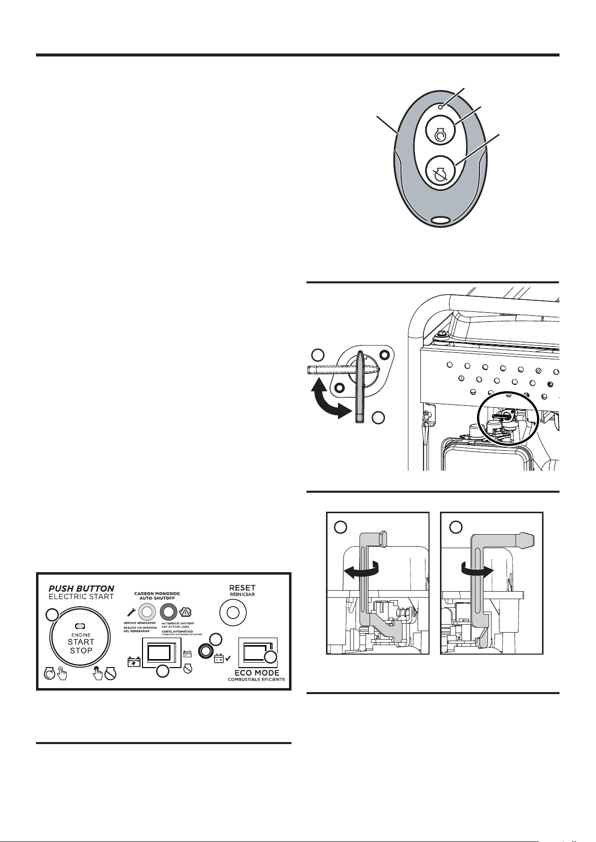
See Figures 16 - 17.
l Make sure the battery is connected.
l Push the battery switch to the ON position.
NOTE: When battery power is available, the battery indi-
cator light will illuminate and the LED around the engine
start/stop button will illuminate solid green.
l Press and hold the engine start/stop button for 10 sec-
onds until the LED around the button ashes green, then
release it.
l Press and hold the start button on the key fob for one
second, then release it.
• If the key fob paired successfully, the LED around the
engine start/stop button will turn solid green.
• If pairing was unsuccessful, the LED around the engine
start/stop button will continue ashing green. Wait
several seconds, then make a second attempt. If the
second attempt fails, turn the battery switch to the OFF
position, wait several seconds and repeat the process.
If subsequent attempts fail, turn the battery switch to
the OFF position and contact customer service.
l After the key fob is successfully paired to the generator,
turn the battery switch to the OFF position.
FIG. 17
A
B
D
START
C
STOP
A - Red LED
B - Start button
C - Stop button
D - Key fob
FIG. 18
B
STARTING THE GENERATOR
See Figures 16 - 21.
l Place the generator in a safe, appropriate location.
l Unplug all loads.
l Ensure the ECO mode switch is in the OFF position.
l Check oil and fuel levels. If needed, add fuel or oil as
described earlier.
l Turn the fuel valve to the ON position.
l Push the battery switch to the ON position.
NOTE: When battery power is available, the battery in-
dicator light and the green LED around the engine start/
stop button will illuminate.
FIG. 16
A
C
D
B
A
A - Fuel valve (open)
B - Fuel valve (close)
FIG. 19
A B
A - Choke (on/cold start)
B - Choke (off/warm start)
A - Engine start/stop button
B - Battery switch
C - Battery indicator
D - ECO mode switch
English | 21
Page 22
OPERATION
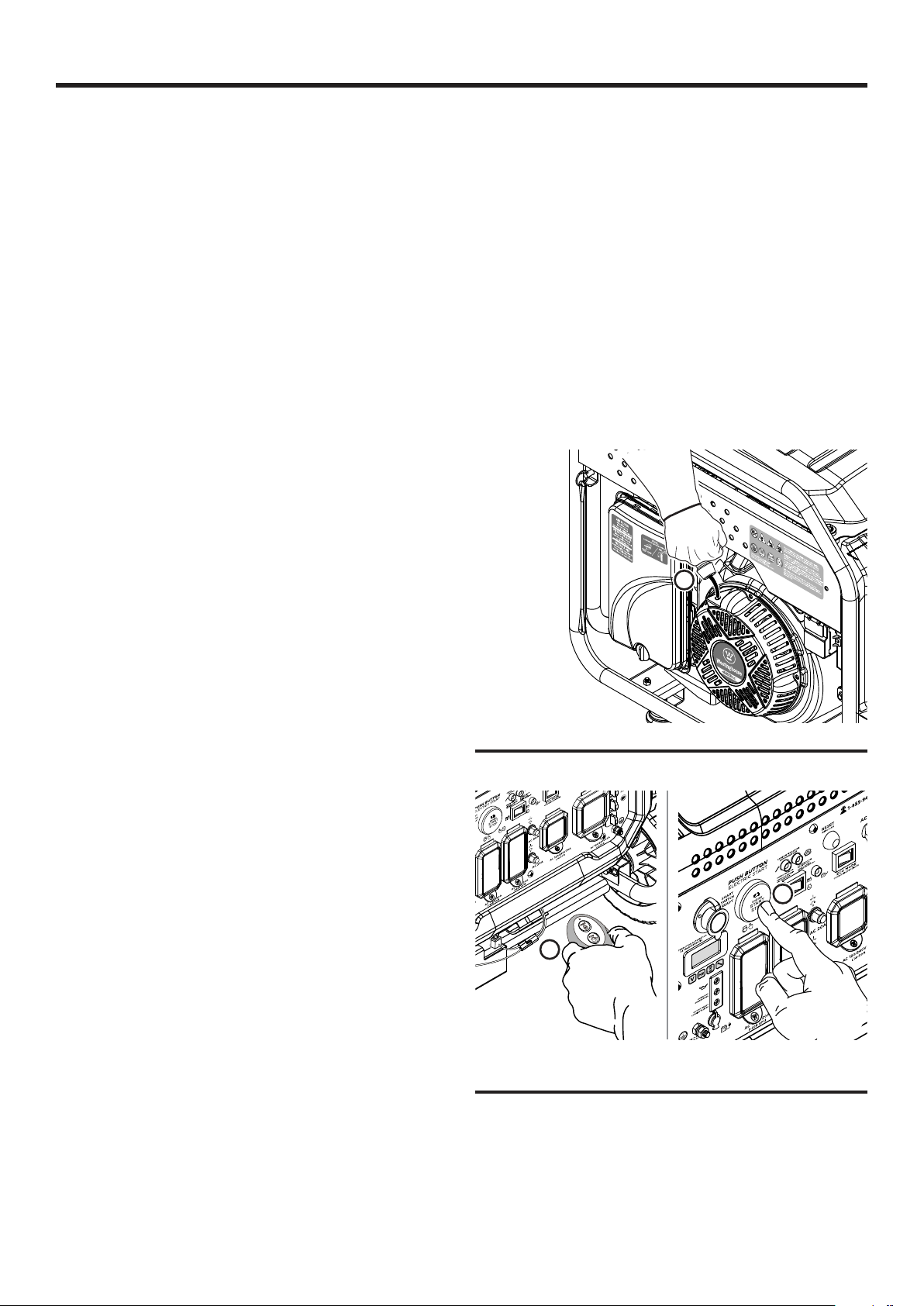
To start the generator using the recoil handle:
l Move the choke to the on/cold start position.
NOTE: If you are re-starting the generator, move the
choke to the off/warm start position.
l Firmly grasp and pull the recoil handle slowly until you
feel increased resistance. At this point, pull the recoil
handle rapidly away from the generator until the engine
starts.
NOTE: Gently return the recoil handle into place after
starting the unit. Do not let it snap back against the unit.
During initial starting, additional pulls may be required
to prime the fuel pump.
l After the engine starts and stabilizes (approximately 5
seconds), move the choke to the off/warm start position.
To start the generator using the remote start feature:
l Push and hold the start button on the key fob for two
seconds.
NOTE: The red LED on the key fob should blink each
time the start button is pressed. If the red LED does not
blink and the generator does not start, then the battery
in the fob may need to be replaced. If the red LED does
blink but the generator does not start, the generator’s
battery may need to charge. Start the unit using the recoil
handle. The generator’s battery will charge as the unit
runs.
To start the generator using the engine start/stop
button:
l Push and hold the engine START/STOP button for two
seconds.
NOTE: If the engine START/STOP button does not start
the generator, the generator’s battery may need to charge.
Start the unit using the recoil handle. The generator’s
battery will charge as the unit runs.
To add loads after starting the generator:
l When the OUTPUT READY LED illuminates, you can
safely connect loads to the control panel receptacles.
NOTE: Verify that all devices are turned off before con-
necting them to the generator.
NOTE: Make sure that the wattage requirements for
all connected devices are in line with your generator’s
capabilities.
l Connect and start the largest device or appliance.
l Allow the generator output to stabilize. Once stable,
the engine should run smoothly, and the device should
function properly.
l Connect and start the next largest device or appliance.
l Allow the generator output to stabilize.
l Repeat this process for each additional load.
STOPPING THE GENERATOR
l Remove any connected loads from the control panel
receptacles.
l Allow the generator to run at “no load” for several
minutes to reduce and stabilize engine and alternator
temperatures.
l Press and hold the engine START/STOP button or the
stop button on the key fob for one second to stop the
generator.
l Push the battery switch to the OFF position.
l Allow the engine to cool, then close the fuel valve.
To stop the unit quickly in an emergency:
l Press and hold the engine START/STOP button or the
stop button on the key fob for one second to stop the
generator.
FIG. 20
A
A - Recoil Handle
FIG. 21
B
A
A - Key Fob
B - Engine start/stop button
22 | English
Page 23
OPERATION
LOW OIL INDICATOR
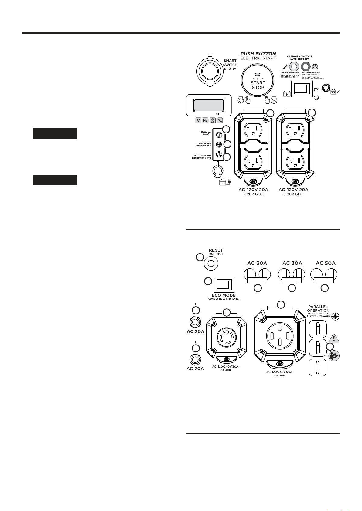
See Figure 22.
The LOW OIL LED on the control panel will illuminate when
the unit is low or out of oil. The generator will not start when
the indicator is lit. To resume normal operation, add engine
oil as described earlier in this section. Do not attempt to
crank or start engine before it has been properly serviced with recommended oil.
ECO MODE
See Figures 22 - 23.
NOTICE
ECO mode switch in the OFF position. Allow the engine speed to stabilize and the OUTPUT READY LED
to illuminate before putting the ECO mode switch in
the ON position.
NOTICE
allel operation with another Westinghouse generator.
ECO mode minimizes fuel consumption and noise by adjusting the engine RPM to the minimum required for the
current load.
Turn ECO mode ON when powering small appliances with
continuous loads such as a computer or electric light.
Turn ECO mode OFF when powering large surge loads
such as an air conditioner or electric pump.
To turn on ECO mode, verify that the OUTPUT READY
LED is illuminated, then push the switch to the ON position.
If no load is present, the generator RPM will drop to idle
speed. The generator will detect loads as they are applied
and increase engine RPM.
To run the generator at maximum power and RPM, push
the ECO mode switch to the OFF position.
Always start the generator with the
Do not use ECO mode when in par-
OVERLOAD RESET
See Figures 22 - 23.
Do not overload the generator. If the generator is
approaching or has reached an overload condition, the
OVERLOAD LED on the control panel will illuminate.
If the generator is close to overloading, the OVERLOAD
LED will blink. Turn off and remove one or more connected
devices to decrease the load and resume normal operation.
If the load is not reduced, the unit will reach an overload
condition. To extend the service life of the generator, avoid
running the unit near capacity.
If the generator is overloaded or if there is a short circuit in
a connected device, the OVERLOAD LED will turn solid,
and the unit will automatically disconnect from the load.
The engine will continue to run, but there will not be any
electrical output.
FIG. 22
D
A
B
C
A - Low Oil LED
B - Overload LED
C - Output ready LED
D - 120 volt AC 20 amp GFCI receptacles
FIG. 23
A
B
C C D
E
E
A - Reset button
B - ECO mode switch
C - 30 amp circuit breaker
D - 50 amp circuit breaker
E - 20 amp circuit breaker
F - 120/240 volt AC 30 amp receptacle
G - 120/240 volt AC 50 amp receptacle
H - Parallel operation outlets
F
D
G
H
English | 23
Page 24
OPERATION
To restore electrical output after an overload:
l Remove any connected loads from the control panel
receptacles.
l Push the RESET button on the control panel until the
OVERLOAD LED goes OFF and the OUTPUT READY
LED is illuminated.
l Reset the circuit breaker(s) if activated.
l Verify that the intended running and surge loads do not
exceed the generator’s capacity.
l Reconnect electrical loads sequentially, allowing the
generator to stabilize after each load is connected.
CIRCUIT BREAKERS
See Figure 23.
The circuit breakers provide protection for individual circuits. The 20A breakers will activate if the duplex 120V receptacles and/or parallel operation outlets exceed 20 Amps.
The 30A breakers limit the current that can be delivered
through the L14-30R receptacles to 30Amps and the 50A
breaker limits the current for the L14-50R receptacle to 50
Amps. If a circuit breaker activates, turn off the connected
device, remove it from the port or outlet, and return the
circuit breaker to on position.
PARALLEL OPERATION
See Figure 23.
WARNING
Never connect or disconnect the parallel cord leads
when a generator is running.
CAUTION
and right cables is very important when the generators are used with a transfer switch to supply power to
a building. To avoid serious personal injury or damage
to electrical devices, including the generators, do not
try to power an electrical system in a building without
using an approved transfer switch.
Fire and electrocution hazard.
Correct connection of the left
NOTICE
compatible can cause a low voltage output that can
damage tools and appliances powered by the generator.
Parallel operation gives you the ability to link to a compatible
Westinghouse generator for combined running and peak
power output.
A Westinghouse 507PC (50-amp) or 304PC (30-amp)
parallel cord (purchased separately) is required for parallel
operation. This cord can be purchased from an authorized
Westinghouse Generator dealer.
NOTE: Compatible Westinghouse generators without
parallel ports can be operated in parallel with the receptacle-mounted parallel cable, Part# 260041.
Refer to the user manual included with your parallel
cord or receptacle-mounted parallel cable for installation and operation instructions.
Connecting to a generator that is not
TRANSPORTING
l Turn off the generator.
l Allow the generator to cool a minimum of 30 minutes
before transporting.
l Replace all protective covers on the generator control
panel.
l Always use the generator’s frame, not the handle, to lift
the unit or attach any load restraints such as ropes or
tie-down straps. DO NOT attempt to lift or secure the
generator by holding onto any of its other components.
l Keep the unit level during transport to minimize the pos-
sibility of fuel leakage or, if possible, drain the fuel or run
the engine until the fuel tank is empty before transport.
CAUTION
the generator or place it on its side. Fuel or oil can
leak and damage to the generator may occur.
Fire hazard. DO NOT up-end
24 | English
Page 25
CARE AND MAINTENANCE
WARNING
the spark plug boot (see gure 27) from the spark
plug when performing maintenance on the generator.
WARNING
with recommended or equivalent replacement parts.
Using an incorrect or incompatible part might create
a hazard that could result in serious personal injury.
WARNING
30 minutes before performing any maintenance procedure.
WARNING
oil or gasoline. Wear protective clothing and equipment. Wash all exposed skin with soap and water.
Prolonged skin contact with gasoline or engine oil
may cause severe skin irritation and other adverse
reactions.
NOTICE
product prior to each use. Look for loose bolts, uid
leaks, and other signs of wear. Replace all damaged
items. For replacement parts or assistance, contact
our customer service team.
Accidental start-up. Disconnect
Replace damaged or worn items
Allow hot components to cool for
Avoid skin contact with engine
Check the physical condition of the
l Remove the air lter from the air cleaner housing and
place it in a suitable cleaning container. Replace the air
lter if damaged.
NOTE: The air lter may be covered in oil. Use an ap-
propriate container.
l Wash the air lter by submerging the lter in a solution
of household detergent soap and warm water. Slowly
squeeze the lter to thoroughly clean.
NOTICE
during cleaning or drying. Only apply slow but rm
squeezing action.
l Rinse the air lter by submerging it in fresh water and
applying a slow squeezing action. Allow the lter to dry
thoroughly.
NOTICE
of the EPA or other governmental agencies for proper
disposal of hazardous materials. Consult local authorities or reclamation facility.
l Dip the air lter in clean engine oil then squeeze out all
excess oil. The engine will smoke when started if too
much oil is left in the lter.
l Install the air lter in the air cleaner housing and reinstall
the air lter cover.
DO NOT twist or tear the air lter
Do not pollute. Follow the guidelines
To prolong the life of this product, follow the care and
maintenance instructions in this section. Do not attempt
to service or replace any recall or warranty parts. Such
repairs must be performed by an authorized service center.
Contact customer service for details.
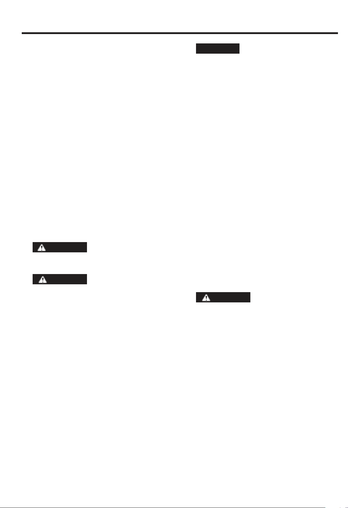
CLEANING THE GENERATOR
Do not store or operate your generator in dirty, dusty, or
corrosive environments. Do not allow foreign materials and
debris to clog the vents on the unit.
NEVER clean the generator with a garden hose. Water can
damage the generator’s fuel system and electrical components. If the unit needs to be cleaned, use a soft brush and
damp cloth to clean the exterior and use low pressure air
(no greater than 25 psi) to clean the vents.
Never use gasoline as a cleaning agent.
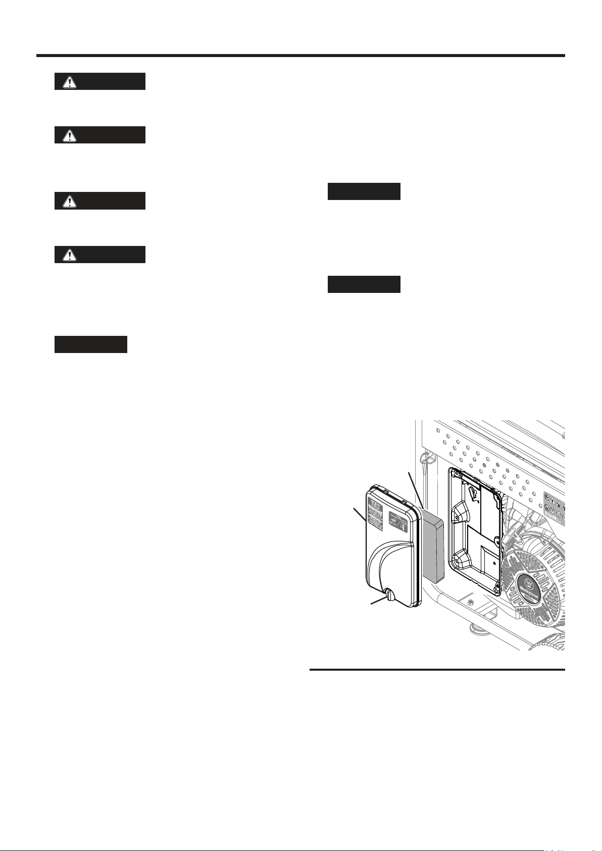
CLEANING/REPLACING THE AIR FILTER
See Figure 24.
Keep air lter clean. A dirty air lter can cause poor performance and decrease the service life of the product.
NEVER operate the generator without an air lter
in place.
l Turn the generator off and allow the engine to cool for
30minutes.
l Rotate the knob counterclockwise and remove the cover.
FIG. 24
B
A
C
A - Air filter cover
B - Air filter
C - Knob
English | 25
Page 26
CARE AND MAINTENANCE
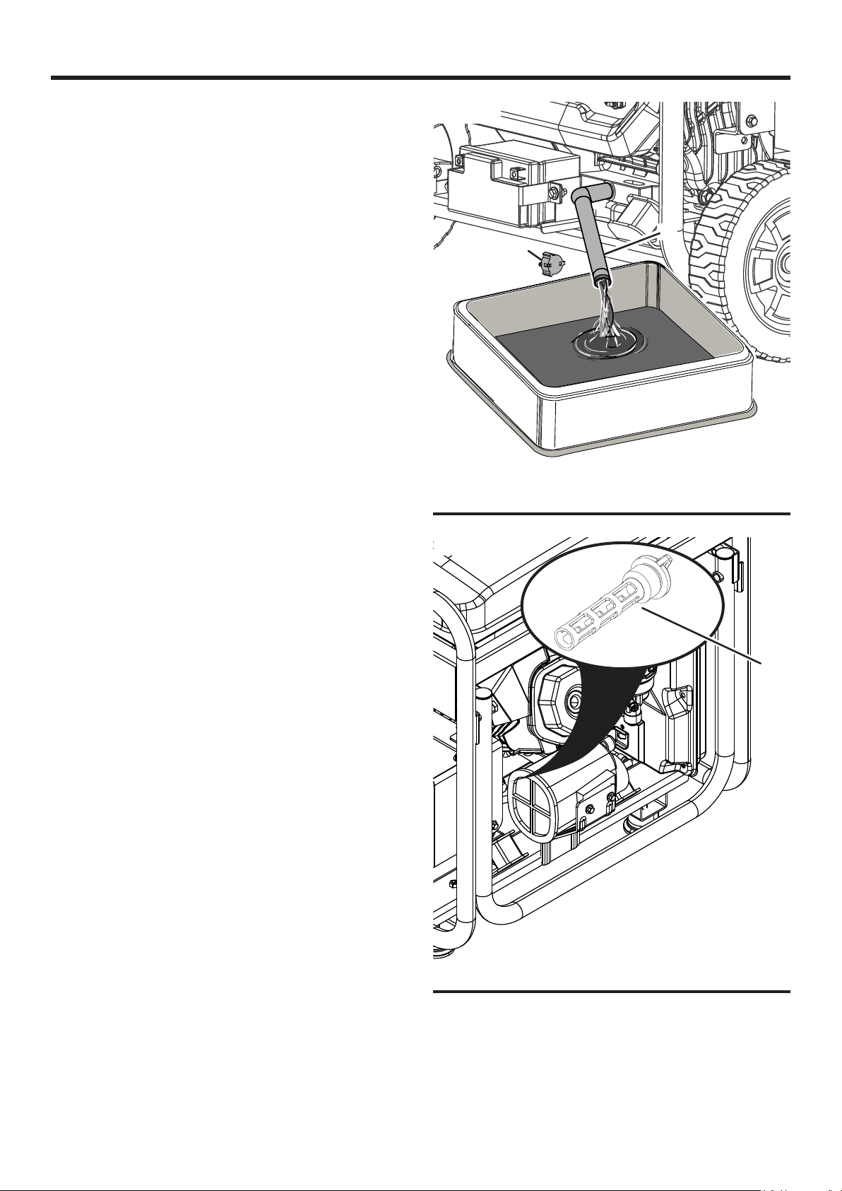
CHANGING THE ENGINE OIL
See Figures 25 - 26.
For optimal performance, change the engine oil and oil
lter according to the gures specied in the maintenance
schedule or the engine manual (if applicable). When using
the generator under extreme, dirty, dusty conditions or in
extremely hot weather, change the oil more frequently.
NOTE: Change the oil while the engine is warm but not
hot. Warm engine oil drains more quickly and thoroughly
than cool lubricant. Contact with hot lubricant will cause
serious burns.
l Turn the generator off and allow the engine to cool for
30minutes.
l Place the generator on a level surface in a well-ventilated
area.
To change the engine oil:
l Clean the area around the oil dipstick.
l Slowly unscrew and remove the oil dipstick.
l Place an oil pan (or suitable container) under the oil drain
hose.
l Unclip the oil drain hose and twist the cap counterclock-
wise to allow the oil the to drain.
l Twist the cap clockwise to close. Secure the hose in the
hose clip.
l Rell the oil as described in the Operations section.
l Replace the oil dipstick and hand-tighten.
l Clean up any spilled oil.
To change the oil lter:
l Clean the area where the oil lter contacts the engine.
l Remove the oil lter by rotating it counterclockwise.
l Using a degreaser or gasoline, clean and inspect the
screen on the oil lter.
NOTE: If the screen is damaged, the lter should be
replaced. Contact customer service for a replacement
lter.
l Install the oil lter and turn it clockwise until it is secure.
DO NOT over tighten.
l Rell the oil as described in the Operations section.
l Replace the oil dipstick and hand tighten.
l Clean up any spilled oil.
FIG. 25
A
B
A - Oil drain hose
B - Cap
FIG. 26
A
26 | English
A - Oil filter
Page 27
CARE AND MAINTENANCE
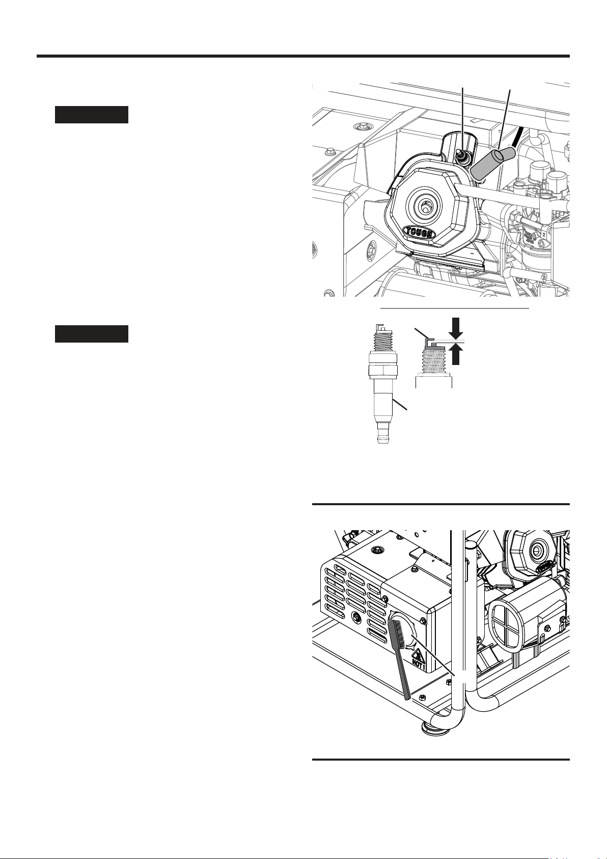
CLEANING/REPLACING THE SPARK PLUG
See Figure 27.
NOTICE
OEM or compatible non-resistor-type spark plug. Use
of resistor-type spark plug can result in rough idling,
misre, or may prevent the engine from starting.
Make sure the spark is clean and properly gapped. To
clean or replace your spark plug:
l Turn the generator off and allow the engine to cool for
30minutes.
l Place the generator on a level surface in a well-ventilated
area.
l Remove the spark plug boot by rmly pulling the spark
boot directly away from the engine.
l Clean the area around the spark plug.
l Remove the spark plug with the included spark plug
socket wrench.
NOTICE
the spark plug laterally when removing the spark plug.
l Inspect the spark plug. Replace if electrodes are pitted,
burned, or the insulator is cracked. Only use a recommended replacement plug.
l Measure the spark plug electrode gap with a wire-type
feeler gauge. If necessary, correct the gap by carefully
bending the side electrode.
Spark plug gap: 0.024 – 0.032 in. (0.60 – 0.80 mm)
l Carefully install the spark plug nger tight, then tighten
as additional 3/8 to 1/2 turn with the spark plug wrench.
l Install the spark plug boot.
ALWAYS use the Westinghouse
Never apply any side load or move
FIG. 27
A - Spark plug
B - Spark plug boot
C - Insulator
D - Electrode
A
D
0.024 - 0.032 in.
(0.60 - 0.80 mm)
C
B
CLEANING THE SPARK ARRESTOR
See Figure 28.
Check and clean the spark arrestor according to the gures
specied in the Maintenance Schedule or the engine
manual (if applicable). Failure to clean the spark arrestor
will result in degraded engine performance.
l Turn the generator off and allow the engine to cool for
30minutes.
l Place the generator on a level surface in a well-ventilated
area.
l Carefully remove the carbon deposits from the spark
arrestor screen with a wire brush. The spark arrestor
must be free of breaks and tears. Use compressed air
to clear removed deposits.
FIG. 28
A
A - Muffler/spark arrestor
English | 27
Page 28
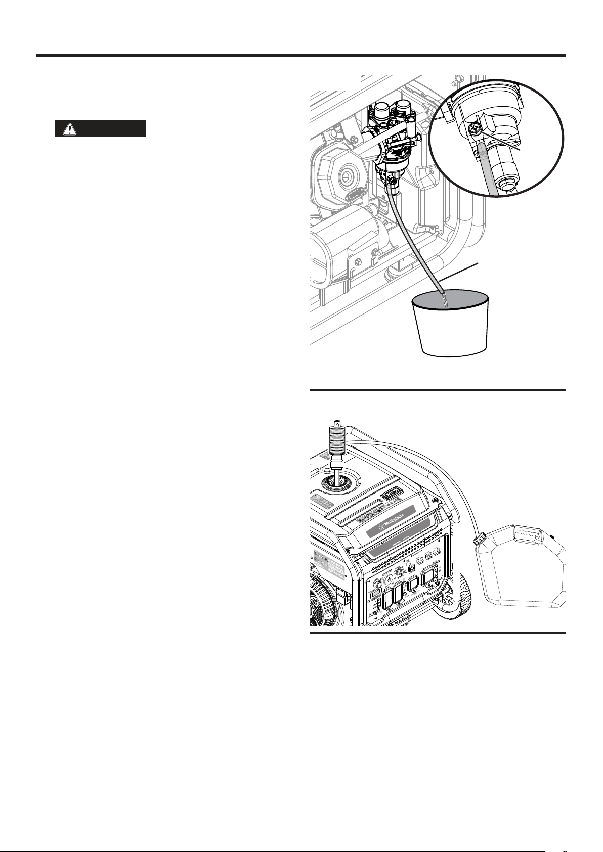
CARE AND MAINTENANCE
DRAINING THE FUEL TANK AND
CARBURETOR FLOAT BOWL
See Figures 29 - 30.
WARNING
container approved for gasoline. Unapproved containers can break or deteriorate allowing gasoline or
gasoline vapors to escape which can create a serious
hazard.
Even properly stabilized fuel can leave residue and cause
corrosion if left long term. If storing the generator for two
to six months, drain the oat bowl to prevent gum and varnish buildup in the carburetor. If storing the generator for
longer than six months, drain the fuel tank to prevent fuel
separation, deterioration, and deposits in the fuel system.
l Turn the generator off and allow the engine to cool for
30minutes.
l Place the generator on a level surface in a well-ventilated
area.
To drain the oat bowl:
l Locate the drain hose extending from the bottom of the
carburetor oat bowl.
l Place the bottom end of the hose outside the generator
into an approved gasoline container to catch the drained
fuel.
l Loosen the oat bowl drain screw and allow the fuel to
drain. Tighten the oat bowl drain screw.
l Route the drain hose between the control panel and the
carbon canister.
To drain the fuel tank:
l Clean area around fuel cap and remove the cap slowly.
l Remove the fuel screen lter by slightly compressing it
while removing it from the tank.
l Using a commercially available gasoline hand pump (not
included), siphon the gasoline from the fuel tank into an
approved gasoline container. DO NOT use an electric
pump.
l Reinstall the fuel screen lter and the fuel tank cap.
l Clean up any spilled fuel.
l Start the generator and allow it to run until the generator
engine stops.
l Push the battery switch to the OFF position.
l Disconnect the battery quick connect cable.
ALWAYS store gasoline in a
FIG. 29
A - Drain screw
B - Drain hose
FIG. 30
20
5.3
00/10000
76
A
B
28 | English
Page 29
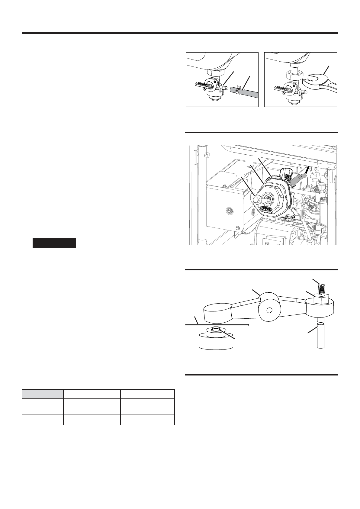
CARE AND MAINTENANCE
REPLACING THE FUEL VALVE
See Figure 31.
Overtime, the fuel lter inside the fuel valve may become
dirty or clogged. To reduce the risk of engine failure, re-
place the entire fuel valve including the lter according to
the gures specied in the maintenance schedule or the
engine manual (if applicable).
l Turn the generator off and allow the engine to cool for
30minutes.
l Drain the fuel tank as described previously.
l Locate the fuel valve and note the valve’s orientation.
NOTE: Place an approved gasoline container beneath
the fuel valve to catch any remaining fuel.
l Using pliers, squeeze the fuel line clip and slide the fuel
line away from the lter.
l Using a wrench (14 mm) [not included], loosen and
remove the fuel valve from the tank.
l Thread the new fuel valve onto the fuel tank and tighten
securely.
l Install the fuel line onto the new fuel valve.
CHECKING/ADJUSTING THE VALVE
CLEARANCE
See Figures 32 - 33.
FIG. 31
A
B
A - Fuel valve
B - Fuel line
C - Wrench (14 mm) [not Included]
FIG. 32
C
A
B
C
NOTICE
ance must be done when the engine is cold.
l Turn the generator off and allow the engine to cool for
30minutes.
l Place the generator on a level surface in a well-ventilated
area.
l Remove the rocker arm cover and carefully remove
the gasket. If the gasket is torn or damaged, it must be
replaced.
l Remove the spark plug so the engine can be rotated
more easily.
l Pull the recoil handle to rotate the engine to top dead
center (TDC). Looking through the spark plug hole; the
piston should be at the top (both valves are closed).
l Both rocker arms should be loose at TDC on the com-
pression stroke. If they are not, rotate the engine 360°.
l Insert a feeler gauge between the rocker arm and the
valve stem to measure valve clearance.
Valve
Clearance
Torque 8 – 12 Nm 8 – 12 Nm
l If an adjustment is necessary, loosen the jam nut.
l Slide the appropriate feeler gauge between the rocker
arm and the valve stem.
l Tighten the adjustment screw onto the push rod to obtain
the specied clearance.
Checking and adjusting valve clear-
Intake Valve Exhaust Valve
0.0031 – 0.0047 in
(0.08 – 0.12 mm)
0.0051 – 0.0067 in
(0.13 – 0.17 mm)
A - Rocker arm cover
B - Bolt
C - Gasket
FIG. 33
D
C
E
A - Adjustment screw
B - Jam nut
C - Feeler gauge
NOTE: You should be able to feel the rocker arm touch
the feeler gauge.
l Hold the adjustment screw in place and tighten the nut.
Torque: 106 inch-pound (12 Nm)
l Recheck valve clearance.
l If no further adjustments are needed, perform this pro-
cedure on the other valve.
l When nished, install the gasket, rocker arm cover, and
spark plug.
D - Rocker arm
E - Valve stem
F - Push rod
A
B
F
English | 29
Page 30
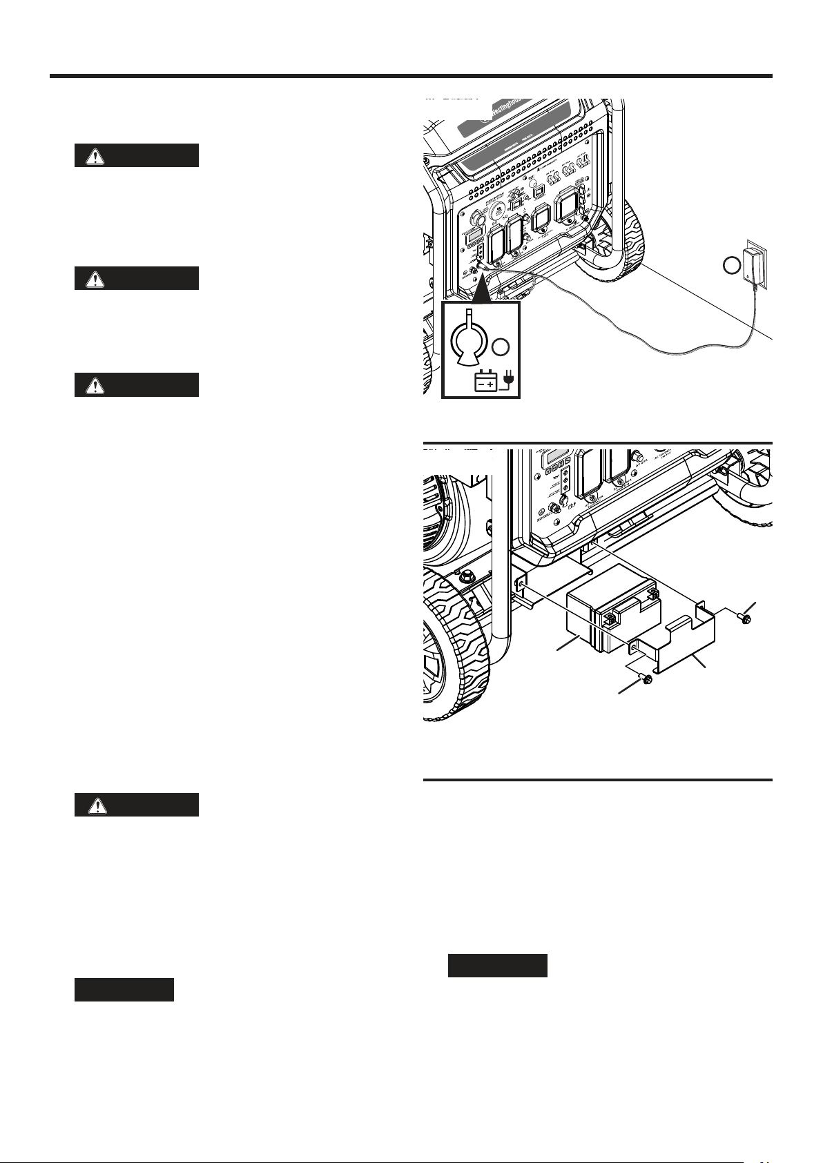
CARE AND MAINTENANCE
BATTERY MAINTENANCE
See Figure 34.
WARNING
hydrogen gas during normal operation. A spark or
ame can cause the battery to explode with enough
force to kill or seriously hurt you. Wear protective
clothing and a face shield, or have a skilled technician
perform battery maintenance.
WARNING
tains sulfuric acid (electrolyte) which is highly corrosive and poisonous. Wear protective clothing and eye
protection when working near the battery. Keep children away from the battery.
WARNING
sparks or other sources of ignition. NEVER touch both
battery terminals at the same time with your hand or
any non-insulated tools. If battery acid contacts skin
or clothing, ush immediately with water and neutralize with baking soda.
The battery shipped with the generator has been fully
charged. A battery may lose some charge when not in use
for prolonged periods of time.
NOTE: Once started, the generator will charge the battery
after 30–60 minutes of use.
When the generator is not running, the included trickle
charger can remain connected and will maintain the battery
for an indenite period of time. A red light on the charger
indicates charging in progress. A green light indicates
charging complete. Charge in a dry location.
l Plug the charger into the battery charging port on the
control panel.
l Plug the wall receptacle end of the battery charger into
a 120 Volt AC wall outlet.
The battery gives off explosive
Burn hazard. The battery con-
NEVER smoke or work near
BATTERY REPLACEMENT
See Figure 35 .
FIG. 34
00/10000
76
A
A - Battery charging port
B - Charger
FIG. 35
A - Battery
B - Battery plate
C - Bolt
B
B
A
C
B
CAUTION
lead and lead compounds. Wash hands after handling.
l Remove the two battery plate bolts and battery plate. Tilt
the battery forward and remove.
l Disconnect the negative (–) cable (black boot) from the
negative (–) battery post.
l Disconnect the positive (+) battery cable (red boot) from
the positive (+) battery post.
NOTICE
lowing sequence to avoid possible shock.
Battery posts, terminals contain
Always connect the cables in the fol-
30 | English
l On the replacement battery, connect the positive (+) bat-
tery cable (red boot) to the battery positive (+) terminal.
Secure the boot over the battery post.
l Connect the negative (–) battery cable (black boot) to
the negative (–) positive terminal. Secure the boot over
the battery post.
l Install the battery in the battery tray. Install the battery
plate and bolts. Tighten the bolts securely.
NOTICE
according to the guidelines established by your local
or state government.
Dispose of the used battery properly
Page 31
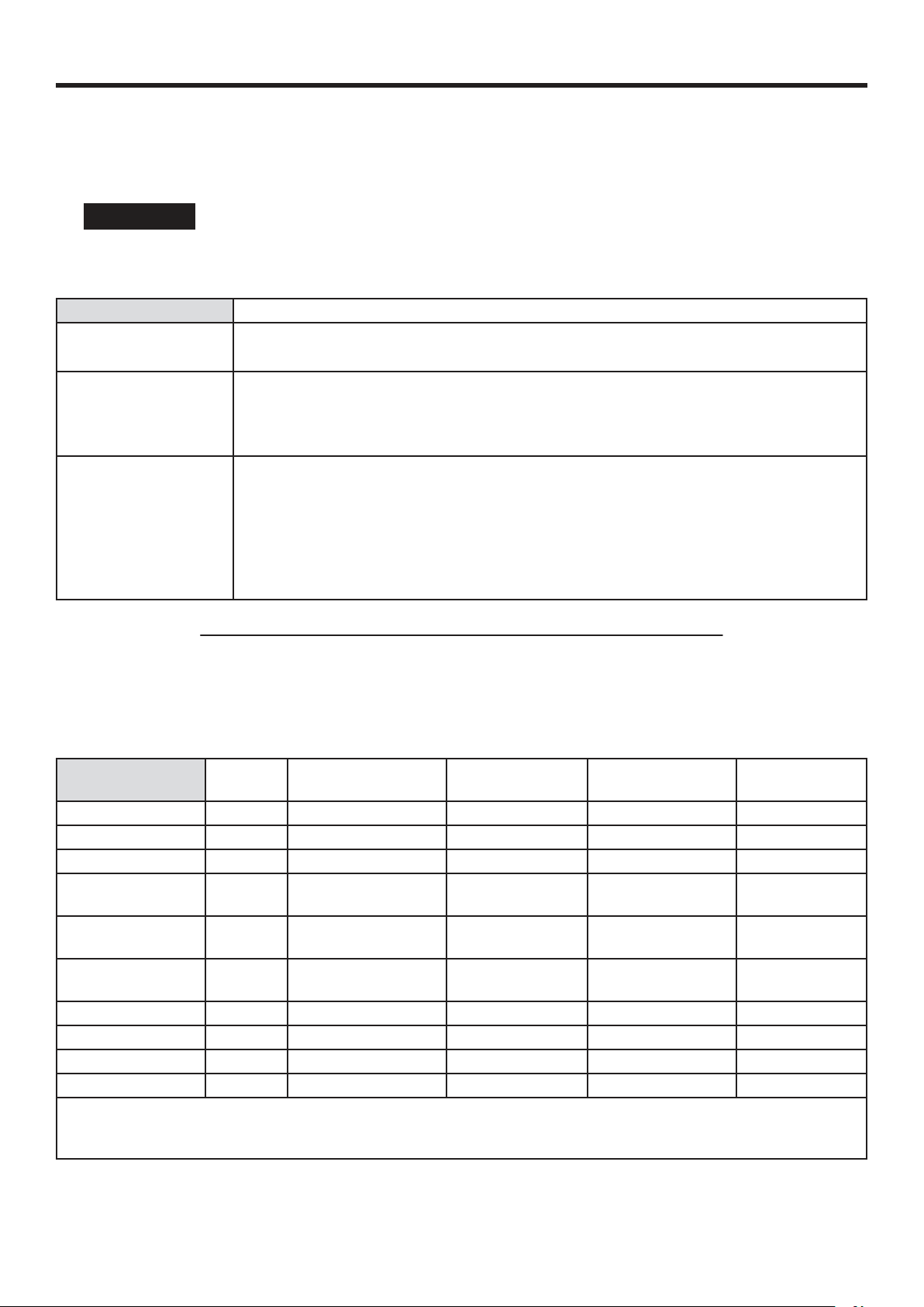
CARE AND MAINTENANCE
STORAGE
Turn the unit off and allow it to cool a minimum of 30 minutes before storage. Keep the unit upright. Do not store the
generator on its side. Drain fuel before storing the unit. Store the unit and the fuel separately in well-ventilated areas
away from sparks, open ames, pilot lights, heat, and other sources of ignition.
NOTICE
Gasoline stored for as little as 30 days can deteriorate, causing gum, varnish, and corrosive build-
up in fuel lines, fuel passages, and the engine. This corrosive buildup restricts the ow of fuel, which can prevent the
engine from starting after a prolonged storage period. The use of fuel stabilizer signicantly increases the storage
life of gasoline. Full-time use of fuel stabilizer is recommended. Follow the manufacturer’s instructions for use.
STORAGE TIME RECOMMENDED PROCEDURE
Less than 1 month
Replace all protective covers on the generator control panel.
Clean the exterior of the generator and remove any debris from the mufer cooling vents.
Replace all protective covers on the generator control panel.
2 to 6 months
Clean the exterior of the generator and remove any debris from the mufer cooling vents.
Drain the carburetor oat bowl. (Store gasoline in an approved gasoline container or dis-
pose of it according to state and local ordinances.)
Replace all protective covers on the generator control panel.
Clean the exterior of the generator and remove any debris from the mufer cooling vents.
Drain the carburetor oat bowl and the fuel tank.(Store gasoline in an approved gasoline
6 months or longer
container or dispose of it according to state and local ordinances.)
Put a tablespoon of engine oil into the spark plug cylinder. Gently pull the recoil handle to
slowly turn the engine and distribute the lubricant. Reinstall the spark plug
Change the engine oil.
MAINTENANCE SCHEDULE
Regular maintenance will improve performance and extend the service life of the generator. Follow the hourly or calendar
intervals, whichever occurs rst. More frequent service is required when operating in adverse conditions as noted below.
NOTE: If your product has a separate engine manual, disregard the information in this chart and follow the instructions in the engine manual.
Before
Each Use
After First 25 Hours
or First Month
After 50 Hours or
Every Six Months
After 100 Hours or
Every Six Months
After 300 Hours
or Every Year
Check Engine Oil X
Change Engine Oil
Clean Air Filter
Inspect/Clean
Spark Arrestor
Inspect/Clean
Spark Plug
Inspect/Adjust
Valve Clearance
1
2
X X
X
X
X
3
X
Replace Spark Plug X
Replace Air Filter X
Replace Oil Filter X
Replace Fuel Valve X
1
Change oil every month when operating under heavy load or in high temperatures.
2
Clean more often under dirty or dusty conditions. Replace air lter if it cannot be adequately cleaned.
3
Recommend service to be performed by authorized Westinghouse service dealer.
English | 31
Page 32
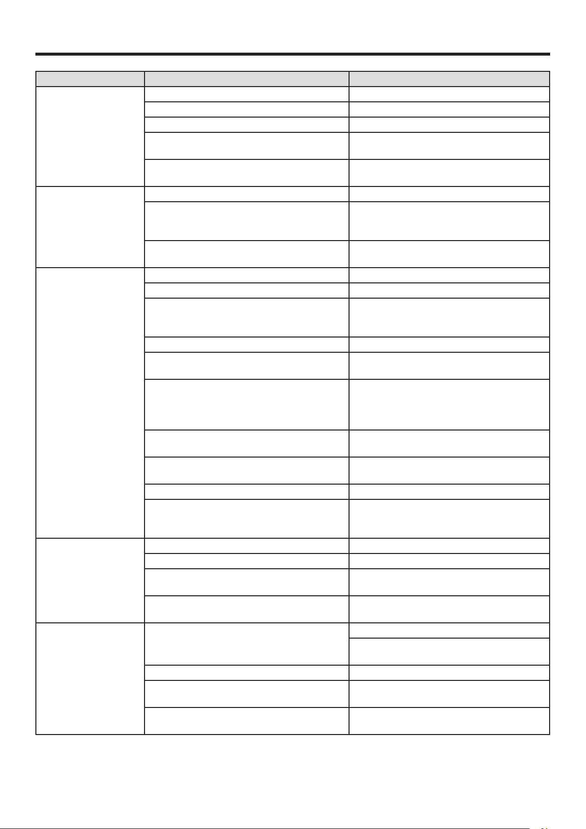
TROUBLESHOOTING
PROBLEM POSSIBLE CAUSE CORRECTION
Fuel level is low or depleted. Refuel.
Incorrect engine oil level. Check engine oil level.
Engine starts, then
shuts down
Engine lacks power
Engine will not start
Engine runs rough
or bogs when load
applied
No power at AC
receptacles
Dirty air lter. Clean the air lter.
Contaminated gasoline. Drain the fuel tank. Refuel with fresh
gasoline.
Defective low oil level switch. Contact Westinghouse customer service
toll-free at 1 (855) 944-3571.
Air lter restricted. Clean or replace air lter.
Stale gasoline, generator stored without
treating or draining gasoline, or refueled with
bad gasoline.
Fuel system malfunction, ignition
malfunction, valves stuck, etc.
Battery switch in the OFF position. Turn battery switch to the ON position.
Out of fuel. Refuel.
Stale gasoline, generator stored without
treating or draining gasoline, or refueled with
bad gasoline.
Dirty air lter. Clean the air lter.
Low engine oil level stopped generator. If LOW OIL LED illuminated, turn the battery
Spark plug wet with fuel (ooded engine). Wait ve minutes. Turn the battery switch to
Spark plug faulty, fouled, or improperly
gapped.
Fuel system malfunction, ignition
malfunction, valves stuck, etc.
CO sensor removed or modied. Return to original conguration.
CO sensor activated or system fault
occurred.
Dirty air lter. Clean the air lter.
Generator overloaded. Unplug some devices.
Faulty power tool or appliance. Replace or repair tool or appliance. Stop and
Fuel system malfunction, ignition
malfunction, valves stuck, etc.
OUTPUT READY LED is OFF and
OVERLOAD LED is ON.
AC circuit breaker/s tripped. Check AC loads and reset circuit breaker/s.
Faulty power tool or appliance. Replace or repair tool or appliance. Stop
Faulty generator. Contact Westinghouse customer service
Drain the fuel tank. Refuel with fresh
gasoline.
Contact Westinghouse customer service
toll-free at 1 (855) 944-3571.
Drain the gasoline tank. Refuel with fresh
gasoline.
switch to the OFF position. Add engine oil.
the OFF position. Pull recoil handle rapidly
several times. If the generator does not
start, remove spark plug and dry.
Gap or replace the spark plug. Reinstall.
Contact Westinghouse customer service
toll-free at 1 (855) 944-3571.
Relocate generator /
Contact Westinghouse customer service
toll-free at 1 (855) 944-3571.
restart the engine.
Contact Westinghouse customer service
toll-free at 1 (855) 944-3571.
Check AC load. Stop and restart engine.
Check the air inlet. Stop and restart the
engine.
and restart the engine.
toll-free at 1 (855) 944-3571.
32 | English
Page 33

NOTES / NOTAS
Page 34

www.WestinghouseOutdoorPower.com
and Westinghouse are trademarks of Westinghouse Electric Corporation.
Used under license by MWE Investments, LLC.
© 2023 MWE Investments, LLC All Rights Reserved.
iGen4500DFc
122035 Rev01 07/21
122878 Rev02 03/23
ecoGen10000
 Loading...