

Page 1
WARNING
Improper installation,
adjustment, alteration, service
or maintenance can cause
injury or property damage.
Read this instruction manual
thoroughly before installing or
servicing this equipment.
INSTRUCTION MANUAL
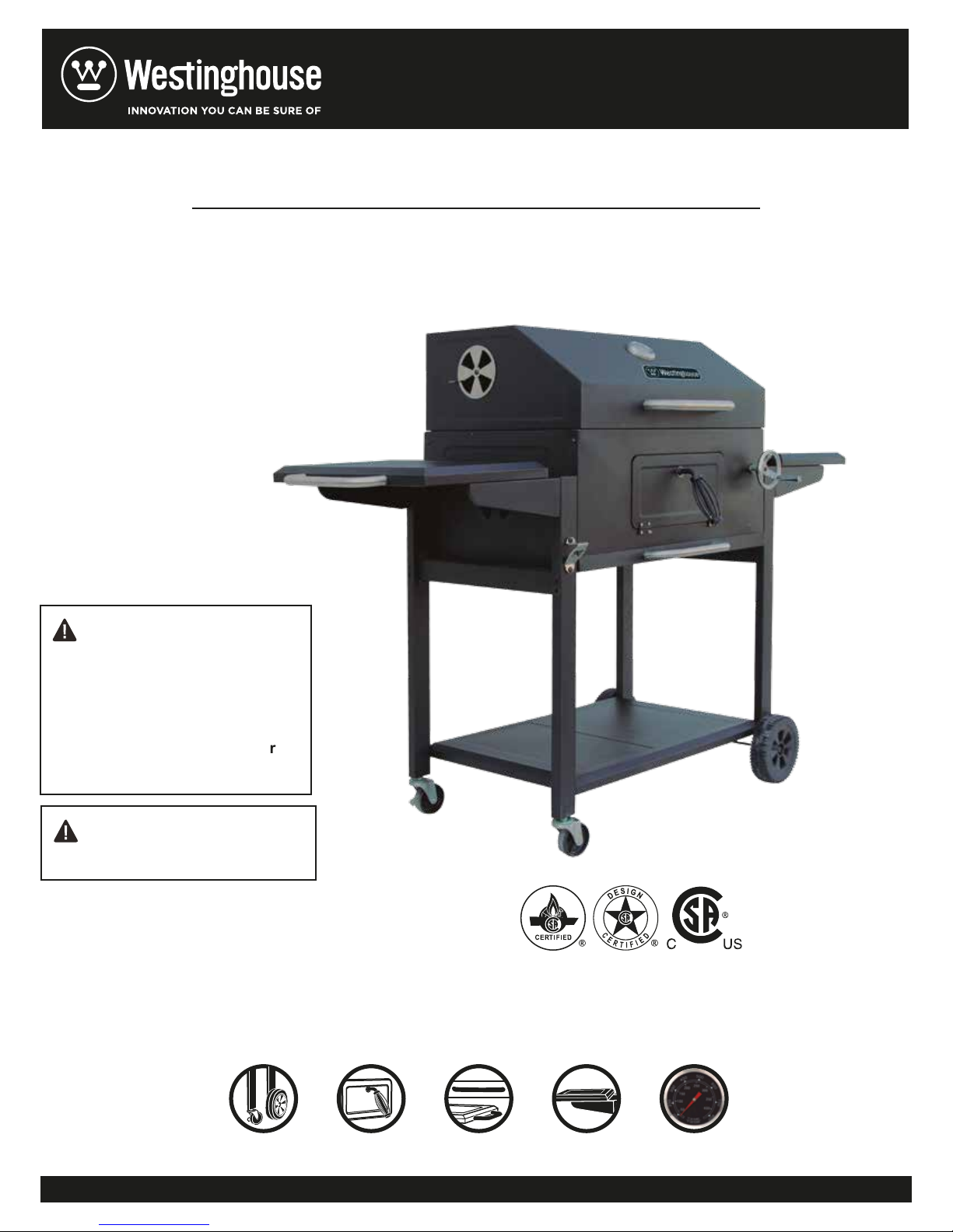
CHARCOAL GRILL
CK171115
WARNING
For Outdoor Use Only
Note : Read and understand this manual before use.
Keep this manual for future reference.
2 CASTERS (WITH LOCK)
STEEL FRONT DOOR2 PLASTIC WHEELS AND
3 STAINLESS
STEEL HANDLES
FIXED TYPE SIDE SHELVES
STAINLESS STEEL
THERMOMETER
Page 2
Assembly Instructions
2
Page 3
PARTS LIST
Part
Description Picture of part Quantity
Nunber
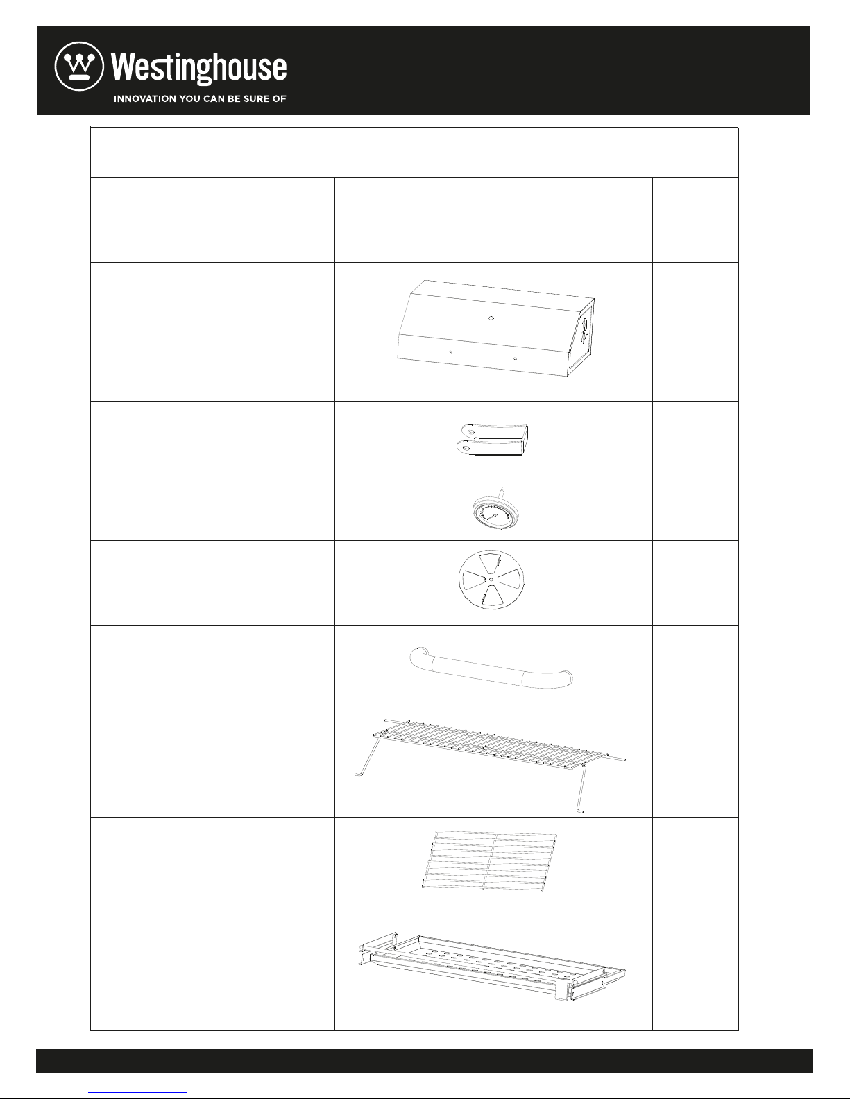
1 TOP 1PCS
2 Up buckle 2PCS
3 1PCS
4 Air flap 4PCS
5 Handle 1PCS
6 Warming grill 1PCS
7 Cooking grill 3PCS
Thermometer
8 Charcoal rack 1PCS
3
Page 4
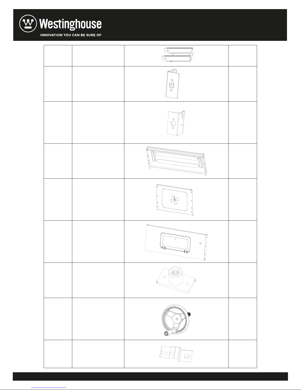
9 Down buckle 2PCS
10 Left stator 1PCS
11 Right stator 1PCS
12 Back plate 1PCS
13 Side plate 2PCS
14 Front plate 1PCS
15
Crankshaft
1PCS
16 Cranking bar 1PCS
17 Front baffle plate 1PCS
4
Page 5
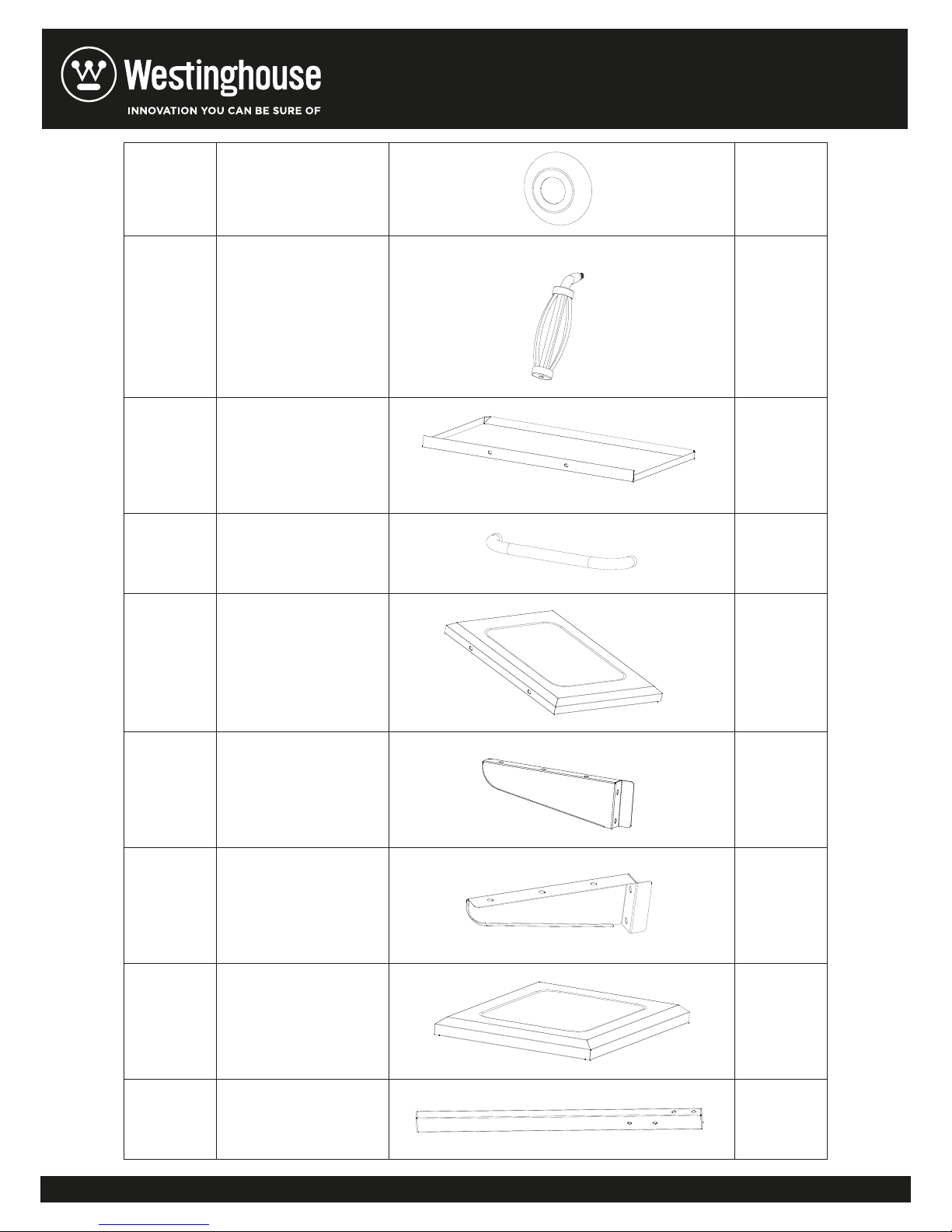
Handle decorativ
e
18
1PCS
sheet
19 Handle 2PCS
20 Oil collector 1PCS
21 Handle 2PCS
22 Left panel 1PCS
23 Support 1 2PCS
24 Support 2 2PCS
25 Right panel 1PCS
26 Left front leg 1PCS
5
Page 6
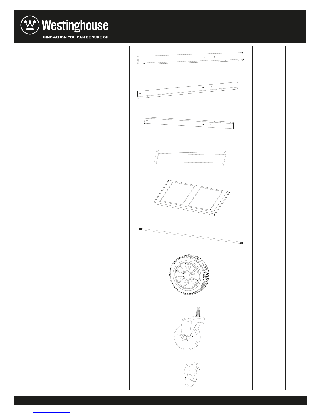
27 Left rear leg 1PCS
g
28 Right front leg 1PCS
29 Right rear leg 1PCS
Frame supportin
30
2PCS
tube
31 Baseboard 1PCS
32
axle
1PCS
33 Wheel 2PCS
wheel (with
34
1PCS
brake)
36 Bottle opener 1PCS
6
Page 7
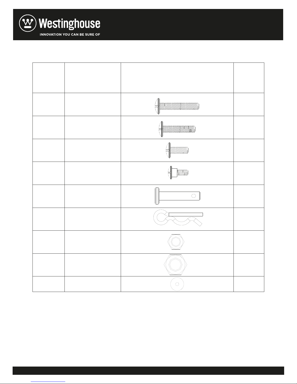
Hardwar
e
Numder
HARDWARE
Description Picture of Hardware Quantity
A
B
C
D
M6*40 screw
M6*35 screw
M6*15 screw
M6 step screw
4PCS
4PCS
64PCS
2PCS
E Shaft 2pcs
F Bolt 2CS
G M6 nut 31PCS
H M8 nut 2PCS
I Gasket 1PCS
IMPORTANT
Please check the pack contents before attempting to assemble this barbecue. A full list of parts
is given on the page 2-6, also directions on what to do if there are damaged or missing parts.
7
Page 8
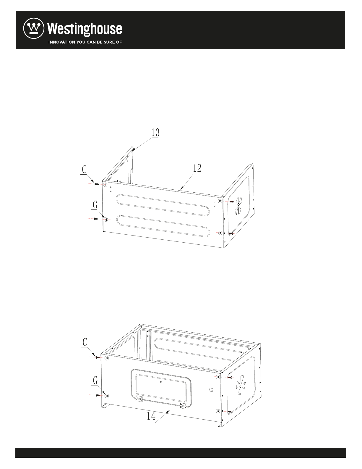
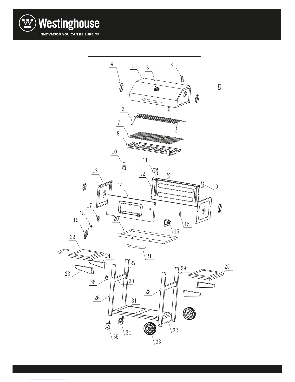
STEP 1: Assembly the side plate (13) and back plate (12) together with 4pcs screw (C) and
4pcs nut (G).
Notice Please make sure to use the first hole and the third hole (From the top to count the holes),
as same as the STEP2
STEP 2: Assembly front plate (14) to the side plate (13) by using 4pcs M6 screw (C) and
4pcs M6 nut (G).
8
Page 9
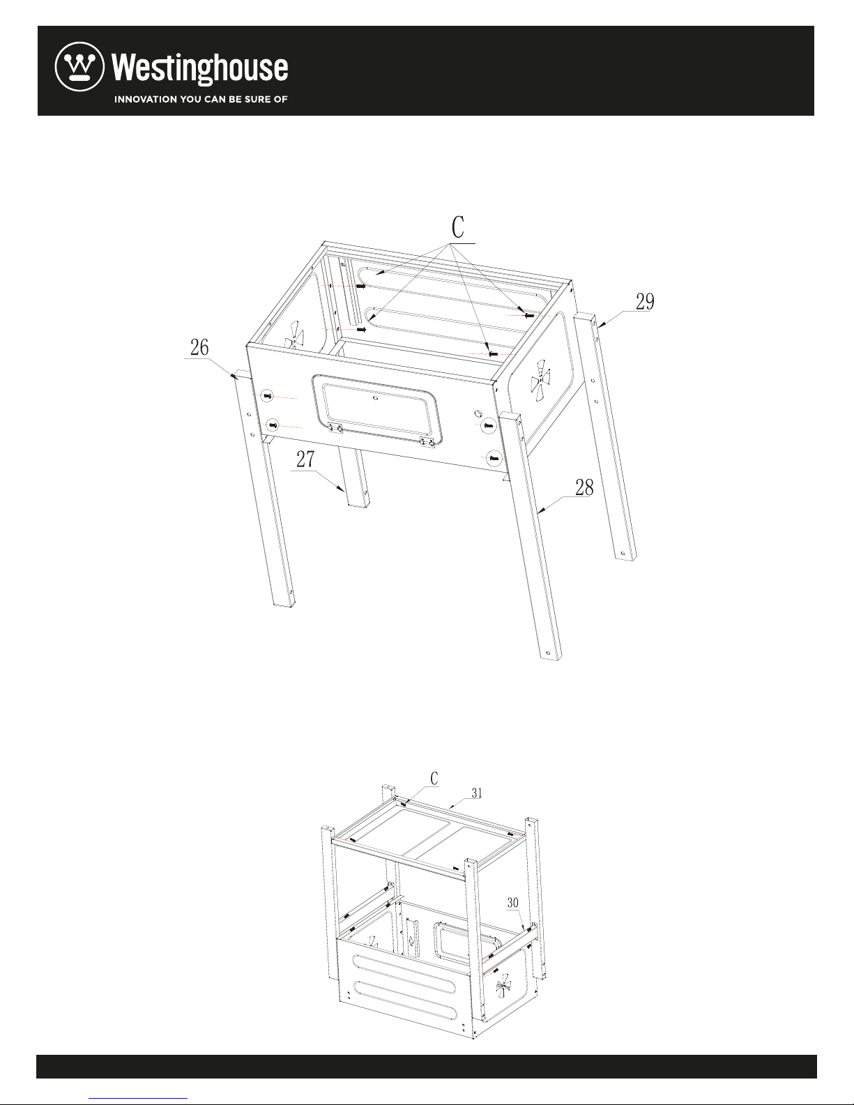
STEP 3: Assembly the right front leg (28) right rear leg (29) left front leg (26) left rear leg
(27) to the fire bowl by using 8pcs M6 screw (C) .
STEP 4: Assemble the frame supporting tube (30) and leg by using M6 screw (C),
assembly the baseboard (31) and leg by using M6 screw (C).
9
Page 10
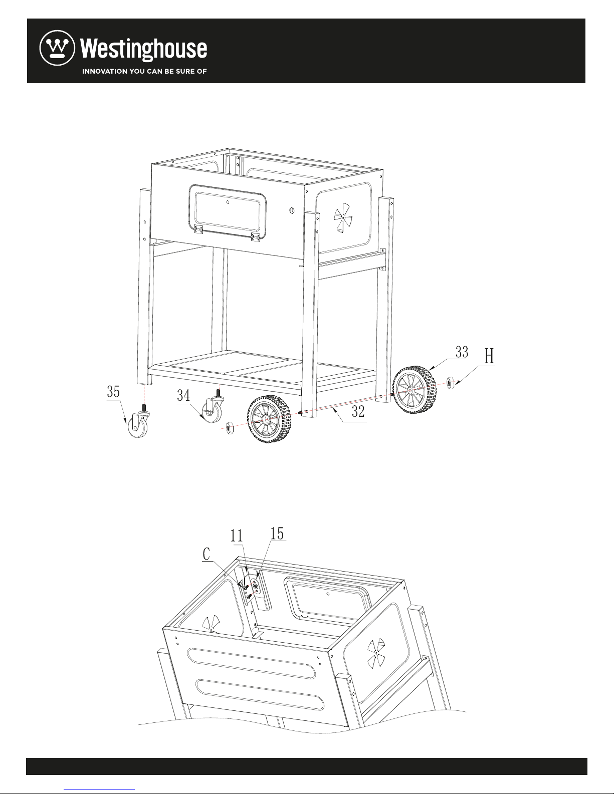
STEP 5: Assembly wheel (34) (35) to the left front leg and left rear leg, assemble the axle (32)
to the right legs, and then assemble the wheels (33) to the axle (32) by using 2pcs M8 nut (H).
STEP 6: As the drawing: Assembly the crankshaft (15) and the right stator (11) and fire bowl
together by using 2pcs screw (C) as below (the crankshaft is upon the stator).
10
Page 11
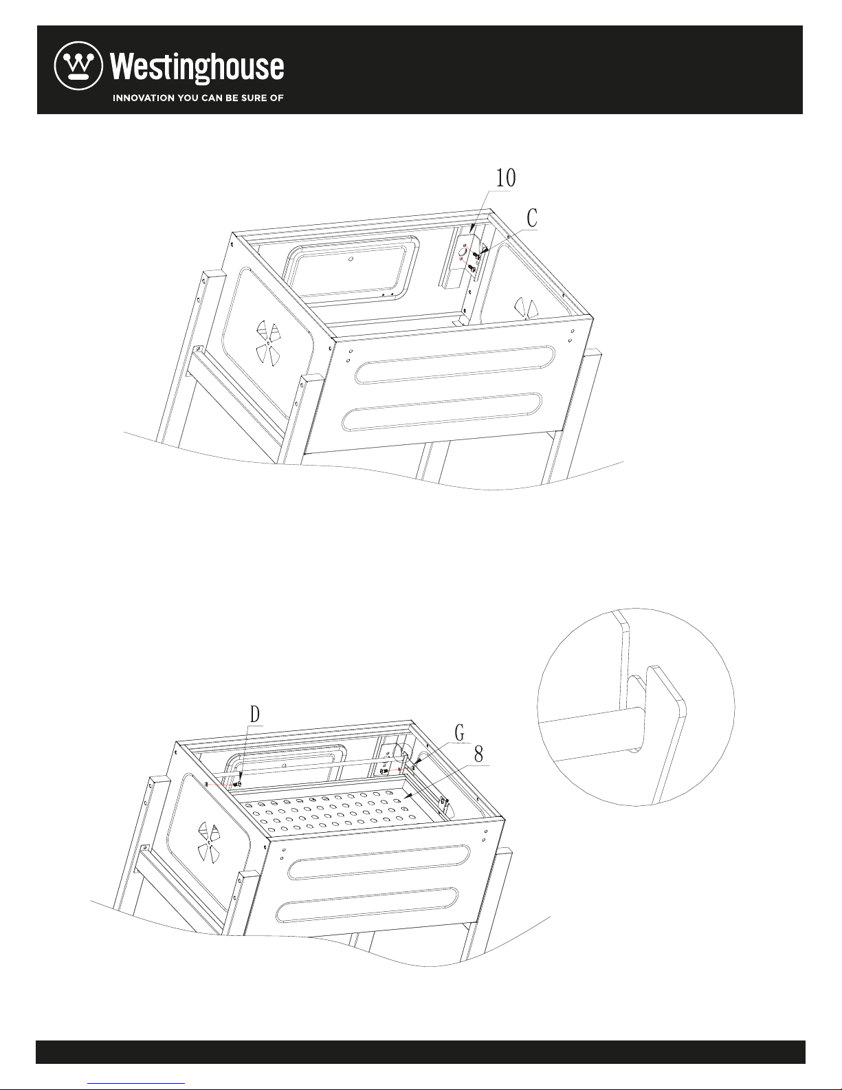
STEP 7: Assembly the left stator (10) and the fire bowl by using 2pcs screw (C).
STEP 8: Assembly the charcoal rack (8) with the stator by using 2pcs step screw (D) and
2pcs nut (G), place it to the slot of the stator.
11
Page 12
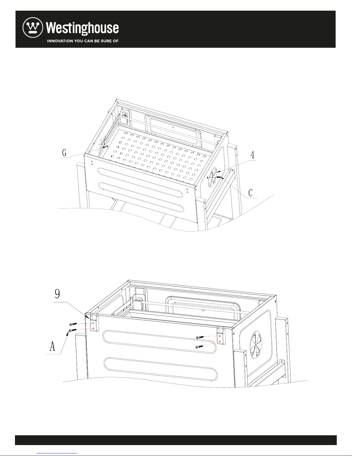
STEP 9: Assembly the air flap (4) to the fire bowl by using 2pcs screw (C) and 2pcs nut (G),
please do not fasten the screw, so that the air flap can be moved.
STEP 10: Assemble the down buckle (9) and the back plate by using 4pcs screw (A).
12
Page 13
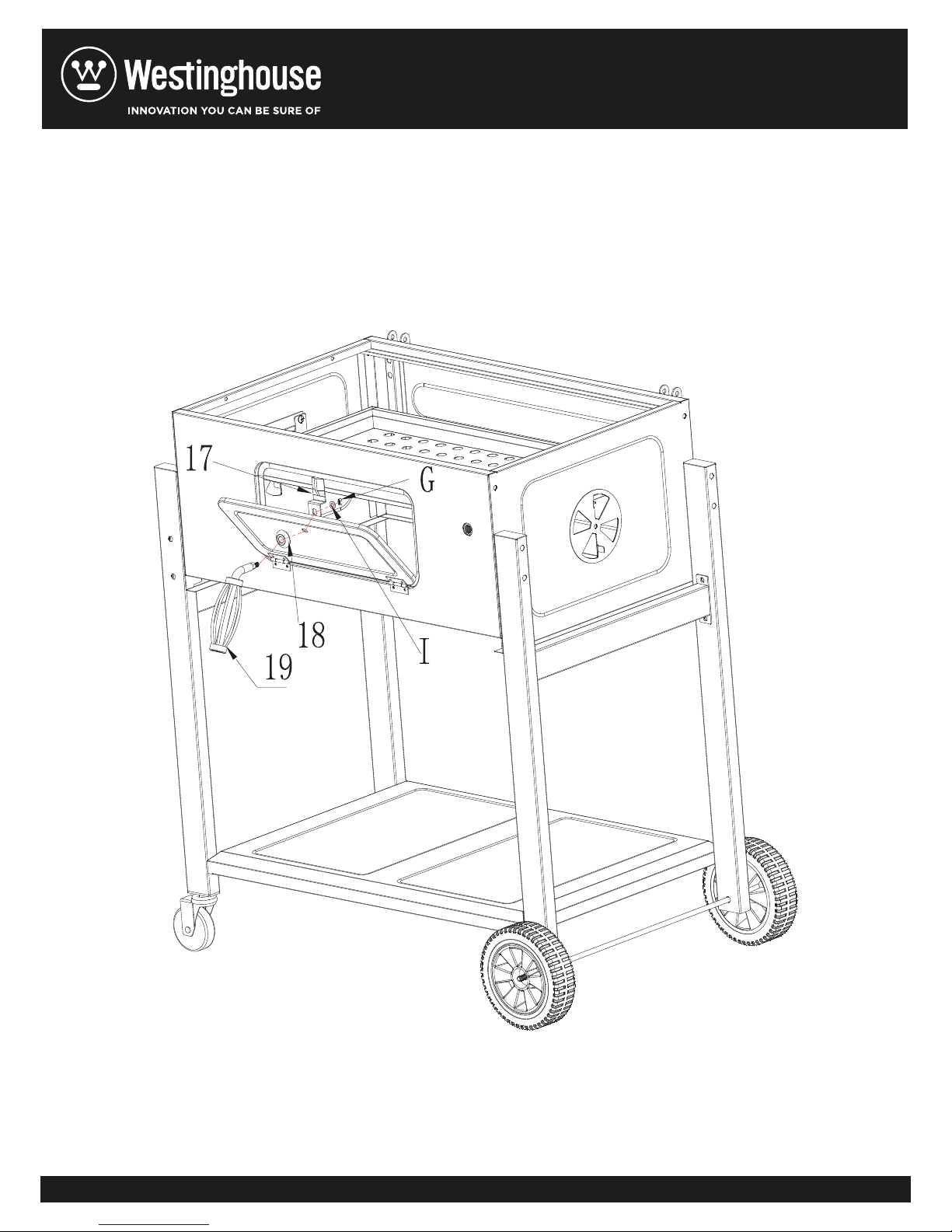
STEP 11: Place the handle decorative sheet (18) on to the handle (19), then assemble the
handle to the front plate (14) by using gasket (I) and M6 nut (G).
Notice: Please pay attention to the direction when assembling the front plate.
13
Page 14
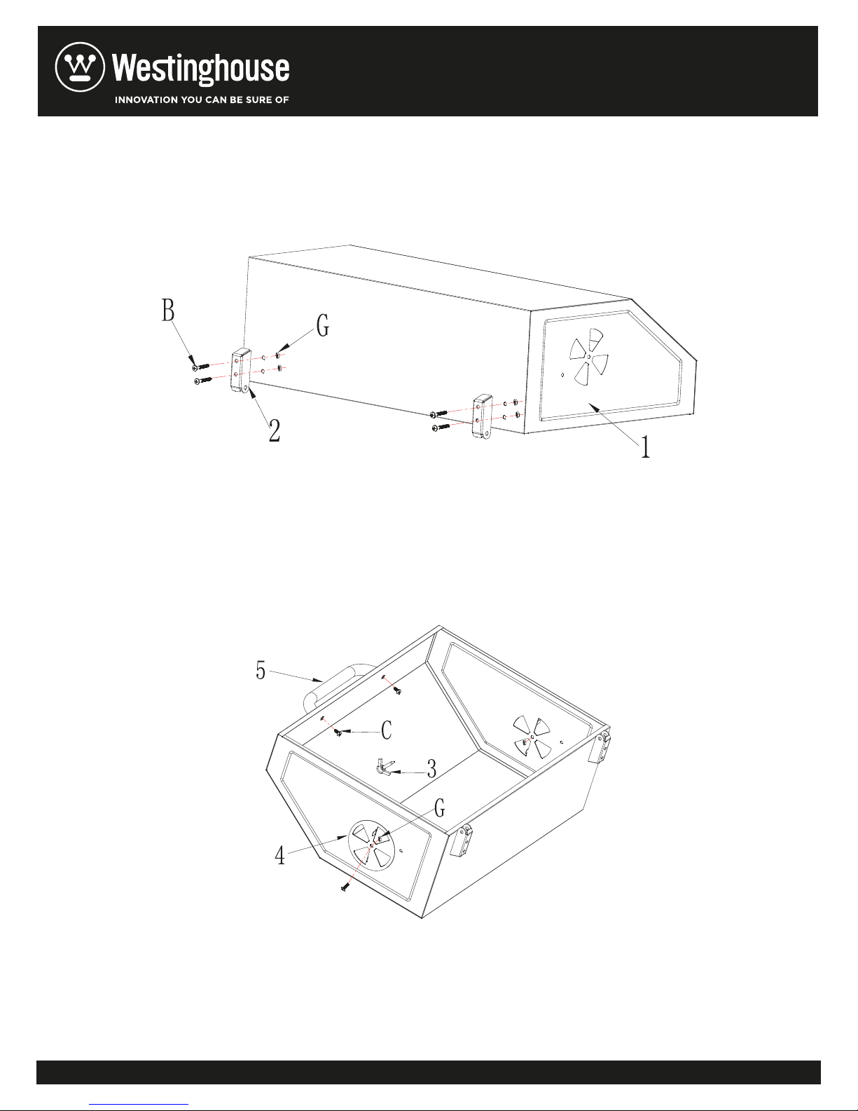
STEP 12: Assembly the up buckle (2) and the cover (1) by using 4pcs screw (B) and 4pcs
nut (G).
STEP 13: Assembly the handle (5) to the cover by using M6 screw (C), assembly the air flap
(4) to the cover by using M6 screw(C), please do not fasten the screw for the air flap, so the it can
be moved. Assemble the thermometer(3) to the cover.
14
Page 15
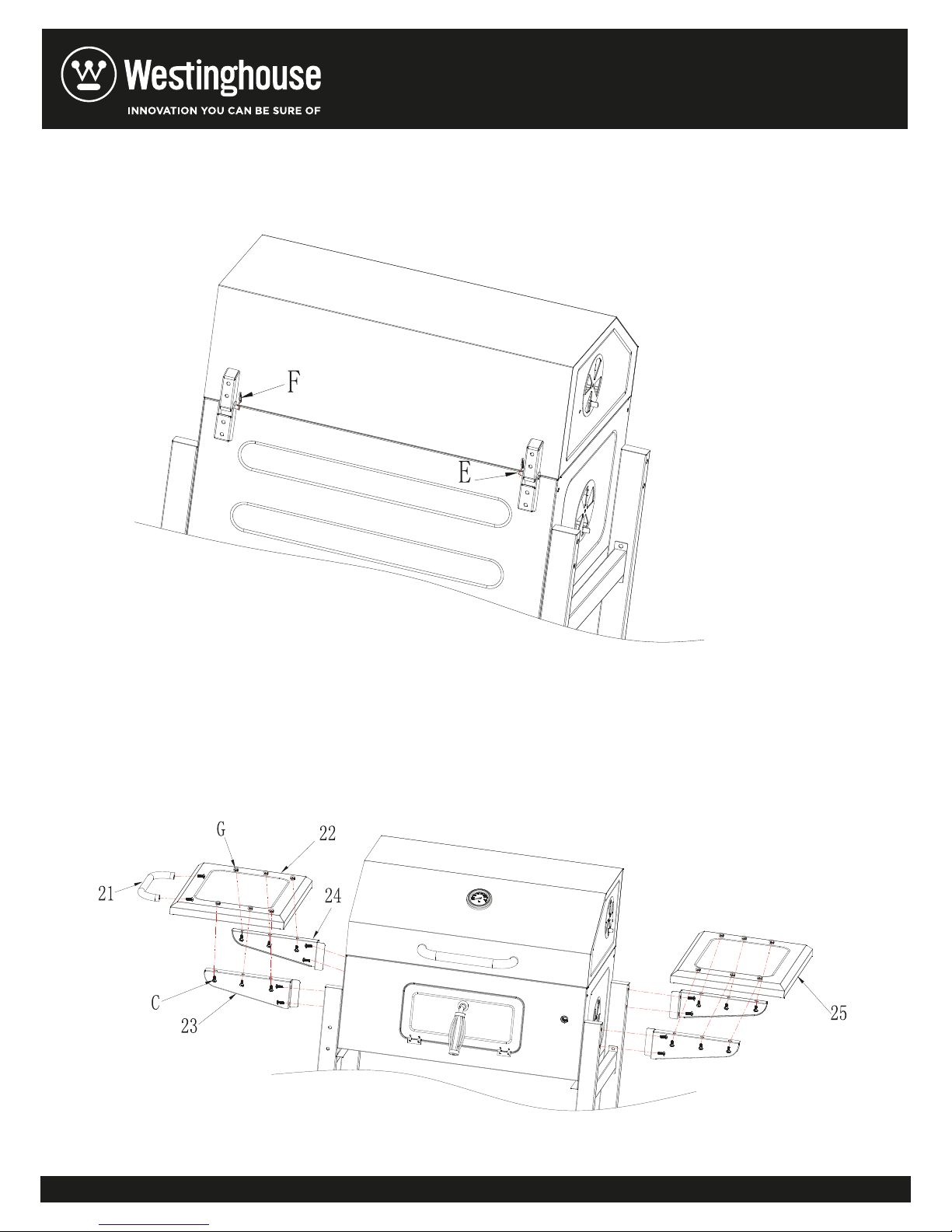
STEP 14: Assemble the cover (1) with the fire bowl by using shaft (E) and bolt (F).
STEP 15: Assembly the handle (21) to the left panel (22) by using M6 screw (C), fix the
support 1(23)& support 2(24) to the left panel (22) by using M6 screw (C) and M6 nut (G), and fix
left panel to the fire bowl by using M6 screw (C). Assembly the right side as same as the left side.
15
Page 16
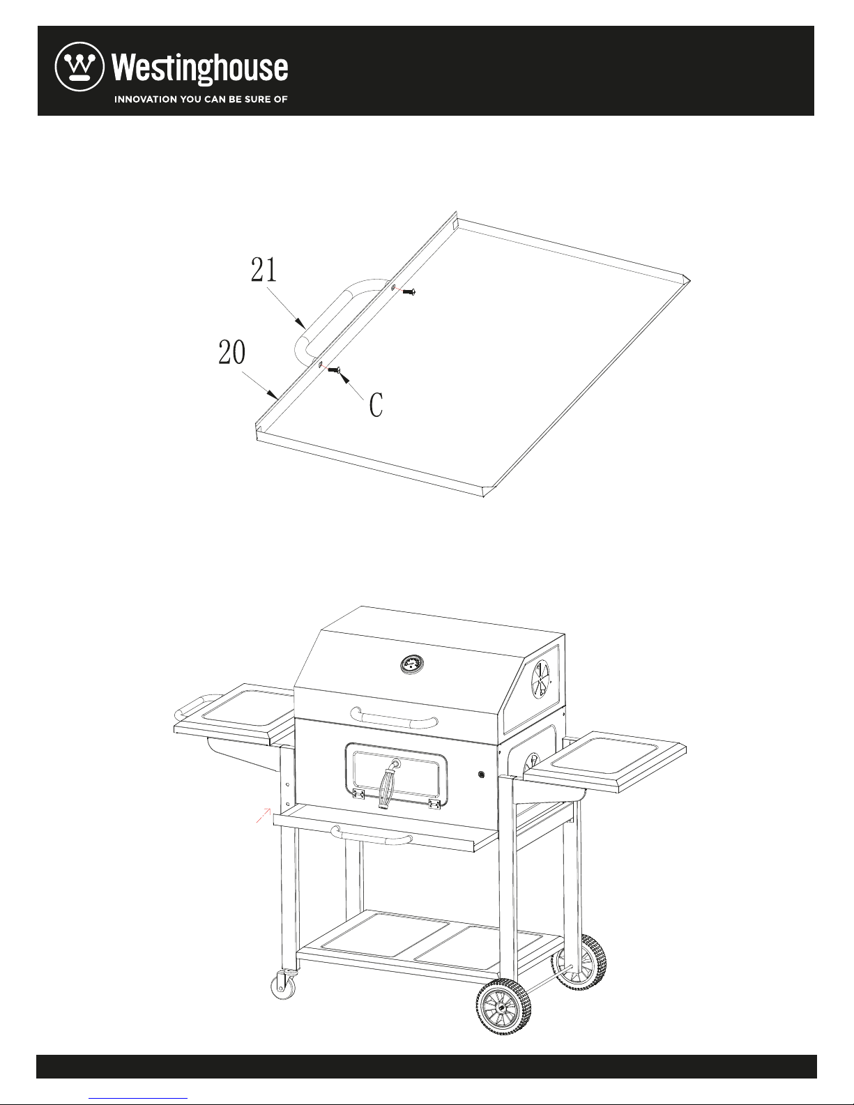
STEP 16: Assembly the handle (21) and the oil collector (20) by using 2pcs screw (C).
STEP 17: Fix the oil collector to the fire bowl.
16
Page 17
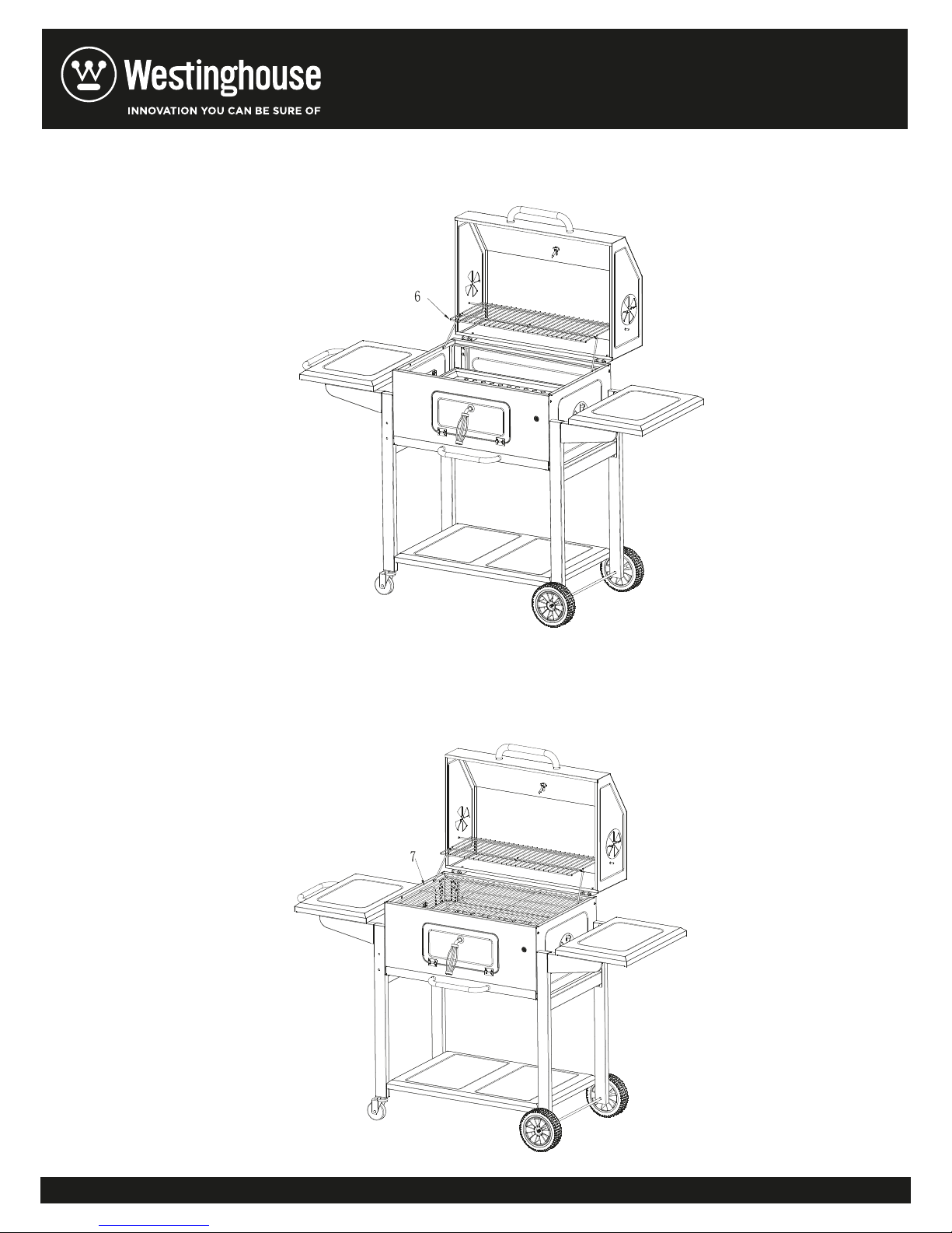
STEP 18: Fix the warming grill to the fire bowl and the cover as below.
STEP 19: Place the cooking grill (7) into the fire bowl.
17
Page 18
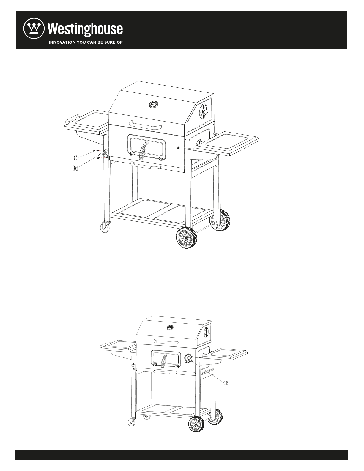
STEP 20:
Fix the bottle opener (36) to the leg by using 2pcs screw (C).
STEP 21:
Fix the cranking bar (16) to the fire bowl as below.
18
Page 19

CAUTION
Use outside only. Never use barbecue inside or in confined space or under canopies
□
or trees.
□
Do not use or pour petrol, methylated spirits or paraffin onto burning coals.
□
Locate on a firm and level surface, away from wooden fences, shrubs, trees, sheds
and fuel tanks.
□
Ensure there is at least 1 metre clearance around all sides of the Barbecue when
in use.
□
Refer to enclosed food safety instructions before beginning to cook.
□
This Barbecue may get very hot
□
An adult should always be in charge of the barbecue.
□
Do not move the Barbecue when in use or when still hot.
□
When adjusting or handling the cooking grill, it is advisable to use heat resistant
gloves.
. Keep young children and pets clear of cooking area.
WARNING
Accessible parts may be very hot. Keep young children away. Use outdoor only. Read the
instructions before using the appliance.
19
 Loading...