

Page 1
Page 2

California
Proposition 65 Warning
The engine exhaust from this product
contains chemicals known to the state of
California to cause cancer, birth defects
or other reproductive harm.
Proposition 65 Warning
Certain components in this product and its
related accessories contain chemicals
known to the state of California to cause
cancer, birth defects or other reproductive
harm. Wash hands after handling.
California
DISCLAIMERS:
All information, illustrations and specifications in this manual are based on the latest information available at
the time of publishing. The illustrations used in this manual are intended as representative reference views only.
Moreover, because of our continuous product improvement policy, we may modify information, illustrations and/or
specifications to explain and/or exemplify a product, service or maintenance improvement. We reserve the right to
make any change at any time without notice. Some images may vary depending upon which model is shown.
ALL RIGHTS RESERVED:
No part of this publication may be reproduced or used in any form by any means – graphic, electronic or
mechanical, including photocopying, recording, taping or information storage and retrieval systems – without the
written permission of Westpro Power Systems, LLC.
2
Page 3
CONGRATULATIONS ON OWNING A WESTINGHOUSE
GENERATOR
!
DANGER
This manual contains important instructions for operating this generator. For your safety and
!
For Your Records:
Date of Purchase: Generator Model Number:
Purchased from Store/Dealer: Generator Serial Number:
Purchase Receipt: (retain your purchase receipt to ensure trouble-free warranty coverage)
Product Registration
To ensure trouble-free warranty coverage, it is important you register your Westinghouse generator. You can register
your generator by either:
1. Filling in the product registration form below and mailing to:
2. Registering your product online at www.westpropower.com
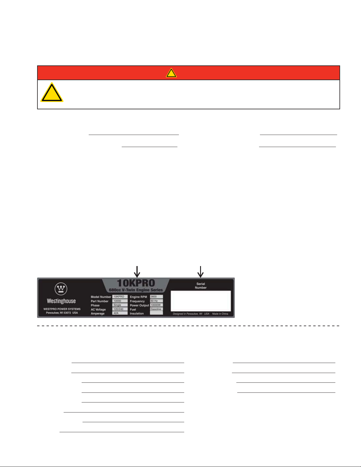
To register your generator you will need to locate the following information:
the safety of others, be sure to read this manual thoroughly before operating the generator.
Failure to properly follow all instructions and precautions can cause you and others to be
seriously hurt or killed.
Product Registration
Westpro Power Systems, LLC
W237 N2889 Woodgate Road, Unit B
Pewaukee, WI 53072
Model Number Serial Number
Class F
Product Registration Form
PERSONAL INFORMATION GENERATOR INFORMATION
First Name: Model Number:
Last Name: Serial Number:
Street Address: Date Purchased:
Street Address: Purchased From:
City, State, ZIP:
Country:
Phone Number:
E-Mail:
Page 4

Page 5

TABLE OF CONTENTS
CONGRATULATIONS ON OWNING A WESTINGHOUSE GENERATOR .........................................................3
For Your Records ..........................................................................................................................................3
Product Registration .....................................................................................................................................3
Product Registration Form ............................................................................................................................3
SAFETY ....................................................................................................................................................................7
SAFETY DEFINITIONS ......................................................................................................................................7
SAFETY SYMBOL DEFINITIONS ......................................................................................................................7
GENERAL SAFETY RULES ...............................................................................................................................8
SAFETY LABELS AND DECALS – 10KPRO ...................................................................................................10
SAFETY LABELS AND DECALS – 8KPRO .....................................................................................................12
UNPACKING ...........................................................................................................................................................14
UNPACKING THE GENERATOR ......................................................................................................................14
WHEEL KIT ACCESSORIES ............................................................................................................................14
Components ...............................................................................................................................................14
ASSEMBLY .............................................................................................................................................................15
ASSEMBLY .......................................................................................................................................................15
INSTALLING THE BATTERY.............................................................................................................................16
FEATURES .............................................................................................................................................................18
GENERAL GENERATOR FEATURES – 10KPRO ............................................................................................18
CONTROL PANEL FEATURES – 10KPRO ......................................................................................................20
GENERAL GENERATOR FEATURES – 8KPRO ..............................................................................................21
CONTROL PANEL FEATURES – 8KPRO ........................................................................................................23
OPERATION ...........................................................................................................................................................24
BEFORE STARTING THE GENERATOR .........................................................................................................24
POWER CORD .................................................................................................................................................25
Using Extension Cords ...............................................................................................................................25
Transfer Switch Cord ..................................................................................................................................26
TRANSFER SWITCH CONNECTIONS ............................................................................................................26
LIFTING BRACKET ..........................................................................................................................................27
GENERATOR ANCHOR ...................................................................................................................................27
ADDING / CHECKING ENGINE FLUIDS AND FUEL .......................................................................................28
Checking and / or Adding Engine Oil ..........................................................................................................28
Adding Gasoline to the Fuel Tank ...............................................................................................................28
PROGRAMMING THE GENERATOR FOR REMOTE START ..........................................................................29
STARTING THE GENERATOR .........................................................................................................................29
STOPPING THE GENERATOR ........................................................................................................................32
Normal Operation .......................................................................................................................................32
During an Emergency .................................................................................................................................32
STARTING THE GENERATOR USING REMOTE START ................................................................................32
STOPPING THE GENERATOR USING REMOTE START................................................................................33
MAINTENANCE ......................................................................................................................................................34
MAINTENANCE ................................................................................................................................................34
Maintenance Schedule ...............................................................................................................................34
ENGINE OIL MAINTENANCE ..........................................................................................................................35
Engine Oil Specification ..............................................................................................................................35
Checking Engine Oil – 10KPRO .................................................................................................................35
Checking Engine Oil – 8KPRO ...................................................................................................................36
Adding Engine Oil – 10KPRO .....................................................................................................................36
Adding Engine Oil – 8KPRO .......................................................................................................................37
Changing Engine Oil – 10KPRO ................................................................................................................37
Changing Engine Oil – 8KPRO ..................................................................................................................38
AIR FILTER MAINTENANCE ............................................................................................................................39
Inspect and Replace the Air Filter – 10KPRO ............................................................................................39
Cleaning the Air Filter – 8KPRO .................................................................................................................
SPARK PLUG MAINTENANCE ........................................................................................................................42
BATTERY SERVICE .........................................................................................................................................43
Battery Replacement ..................................................................................................................................44
40
5
Page 6

TABLE OF CONTENTS
CLEANING THE ENGINE OIL COOLER – 10KPRO ........................................................................................45
TESTING THE GROUND FAULT SENSOR ...................................................................................................... 46
CLEANING THE GENERATOR ........................................................................................................................46
QUICK DRAIN...................................................................................................................................................48
STORAGE .........................................................................................................................................................49
TROUBLESHOOTING ............................................................................................................................................50
TROUBLESHOOTING ......................................................................................................................................50
6
Page 7
SAFETY
SAFETY DEFINITIONS
The words DANGER, WARNING, CAUTION and
NOTICE are used throughout this manual to highlight
important information. Be certain that the meanings of
these alerts are known to all who work on or near the
equipment.
This safety alert symbol appears
with most safety statements. It
!
Indicates a hazardous situation which, if not
avoided, will result in death or serious injury.
Indicates a hazardous situation which, if not
avoided, could result in death or serious injury.
Indicates a hazardous situation which, if not
avoided, could result in minor or moderate injury.
means attention, become alert, your
safety is involved! Please read and
abide by the message that follows
the safety alert symbol.
!
DANGER
!
WARNING
!
CAUTION
SAFETY SYMBOL
DEFINITIONS
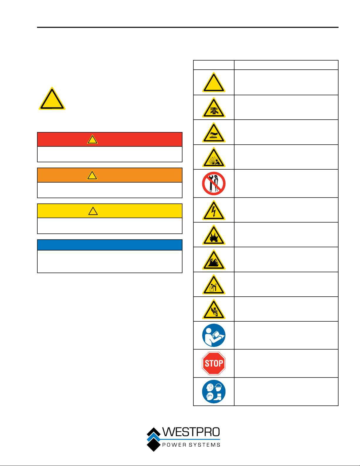
Symbol Description
!
Safety Alert Symbol
Asphyxiation Hazard
Burn Hazard
Burst/Pressure Hazard
Don’t leave tools in the area
Electrical Shock Hazard
Explosion Hazard
NOTICE
Indicates a situation which can cause damage to the
generator, personal property and/or the environment,
or cause the equipment to operate improperly.
OTE:N Indicates a procedure, practice or condition
that should be followed in order for the
generator to function in the manner
intended.
Fire Hazard
Lifting Hazard
Pinch-Point Hazard
Read Manufacturer’s Instructions
Read Safety Messages Before
Proceeding
Wear Personal Protective Equipment
(PPE)
7
Page 8
SAFETY
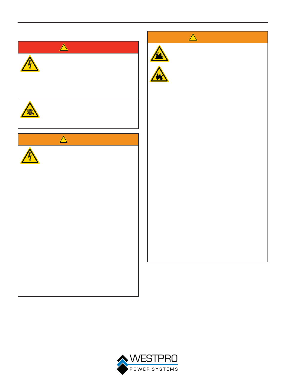
GENERAL SAFETY RULES
!
DANGER
Never use the generator in a location
that is wet or damp. Never expose the
generator to rain, snow, water spray or
standing water while in use. Protect the
generator from all hazardous weather
conditions. Moisture or ice can cause a
short circuit or other malfunction in the
electrical circuit.
Never operate the generator in an
enclosed area. Engine exhaust
contains carbon monoxide. Only
operate the generator outside and away
from windows, doors and vents.
!
WARNING
Voltage produced by the generator
could result in death or serious injury.
• Never operate the generator in
rain or a floodplain unless proper
precautions are taken to avoid being
subject to rain or a flood.
• Never use worn or damaged
extension cords.
• Always have a licensed electrician
connect the generator to the utility
circuit.
• Never touch an operating generator
if the generator is wet or if you have
wet hands.
• Never operate the generator in highly
conductive areas such as around
metal decking or steel works.
• Always use grounded extension
cords. Always use three-wire or
double-insulated power tools.
• Never touch live terminals or
bare wires while the generator is
operating.
• Be sure the generator is properly
grounded before operating.
!
WARNING
Gasoline and gasoline vapors are
extremely flammable and explosive
under certain conditions.
• Always refuel the generator outdoors,
in a well-ventilated area.
• Never remove the fuel cap with the
engine running.
• Never refuel the generator while
the engine is running. Always turn
engine off and allow the generator to
cool before refueling.
• Only fill fuel tank with gasoline.
• Keep sparks, open flames or other
form of ignition (such as match,
cigarette, static electric source) away
when refueling.
• Never overfill the fuel tank. Leave
room for fuel to expand. Overfilling
the fuel tank can result in a sudden
overflow of gasoline and result in
spilled gasoline coming in contact
with HOT surfaces. Spilled fuel
can ignite. If fuel is spilled on
the generator, wipe up any spills
immediately. Dispose of rag properly.
Allow area of spilled fuel to dry
before operating the generator.
• Wear eye protection while refueling.
• Never use gasoline as a cleaning
agent.
• Store any containers containing
gasoline in a well-ventilated area,
away from any combustibles or
source of ignition.
• Check for fuel leaks after refueling.
Never operate the engine if a fuel leak
is discovered.
8
Page 9
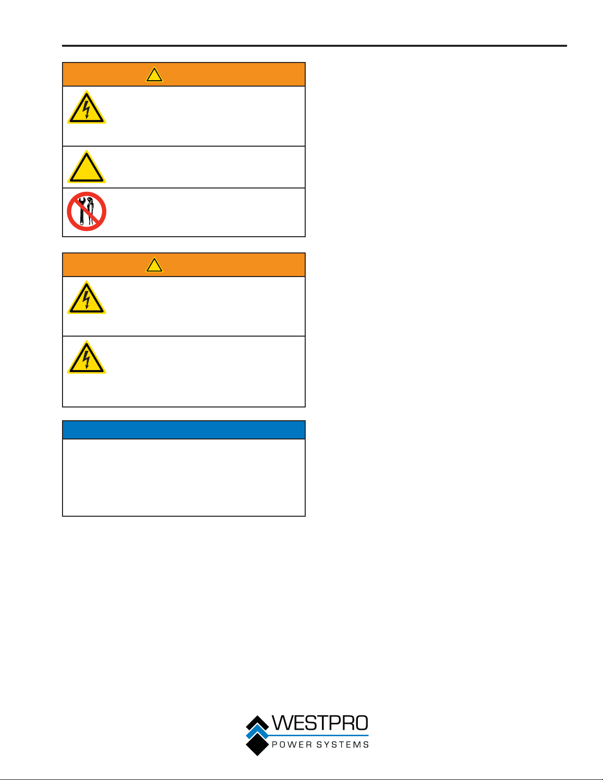
!
!
WARNING
Never operate the generator if powered
items overheat, electrical output drops,
there is sparking, flames or smoke
coming from the generator, or if the
receptacles are damaged.
Never use the generator to power
medical support equipment.
Always remove any tools or other
service equipment used during
maintenance from the generator before
operating.
!
WARNING
Always use caution when around the
generator. The generator is equipped
with a remote start feature that could
be activated, allowing the generator to
start without warning.
Always disconnect the negative
(-) battery cable when servicing or
performing any maintenance on the
generator. This will disable the remote
start system, which will prevent
accidental starting of the generator.
SAFETY
NOTICE
Never modify the generator.
Never operate the generator if it vibrates at high
levels, if engine speed changes greatly or if the
engine misfires often.
Always disconnect tools or appliances from the
generator before starting.
9
Page 10
SAFETY
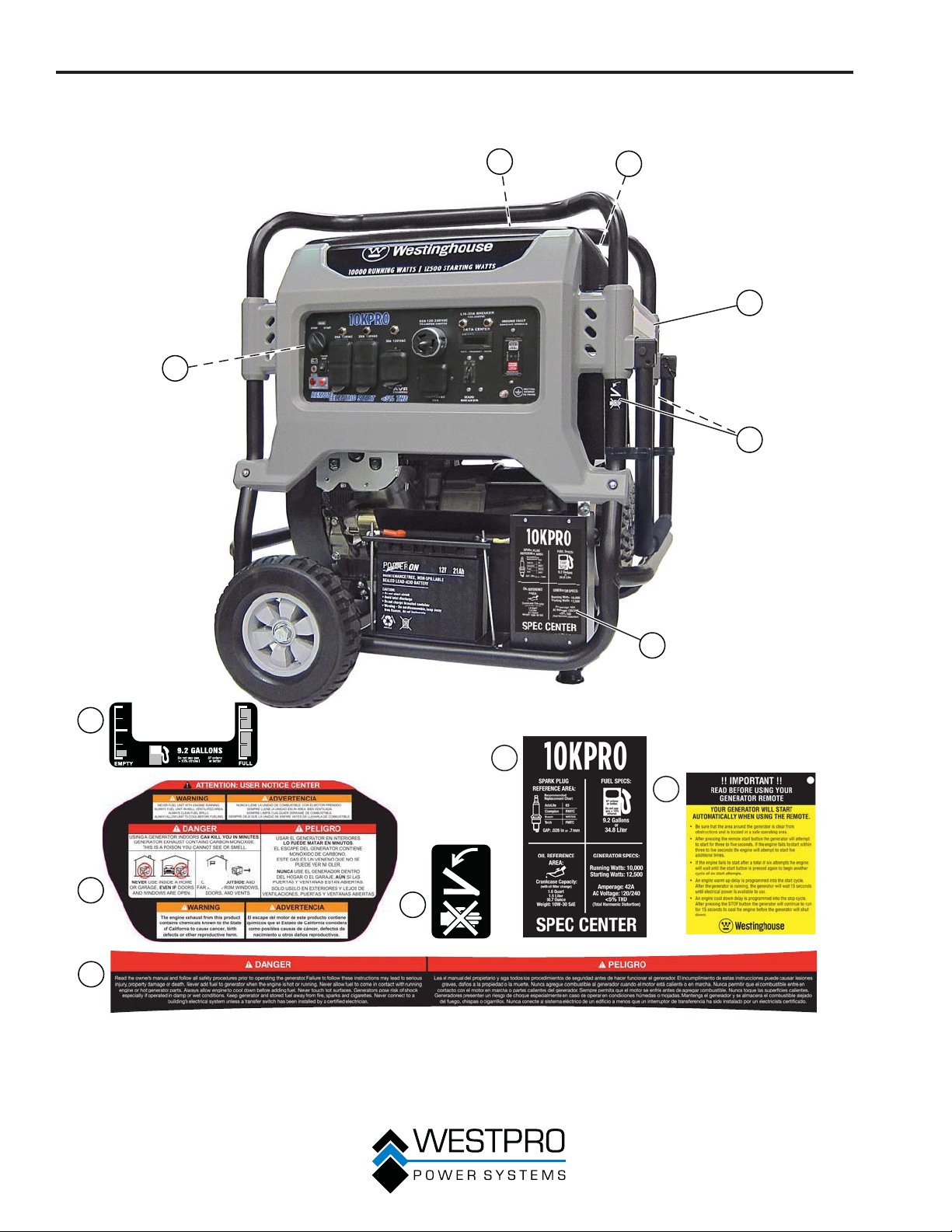
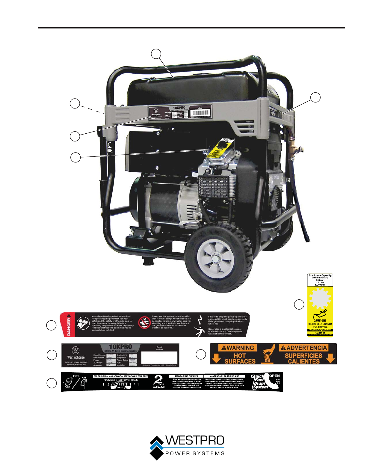
SAFETY LABELS AND DECALS – 10KPRO
1
6
2
3
4
5
1
5
6
2
3
4
Figure 1
10
Page 11
SAFETY
1
3
4
2
5
5
1
2
Class F
4
3
Figure 2
11
Page 12
SAFETY
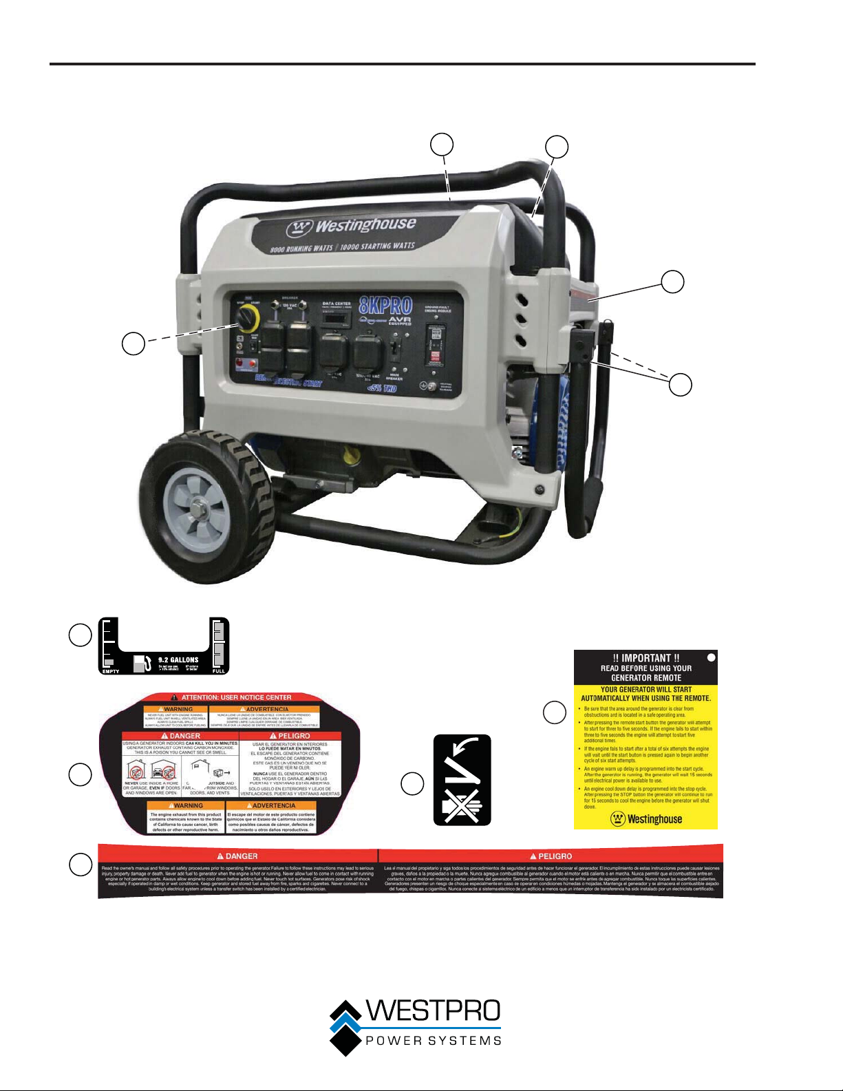
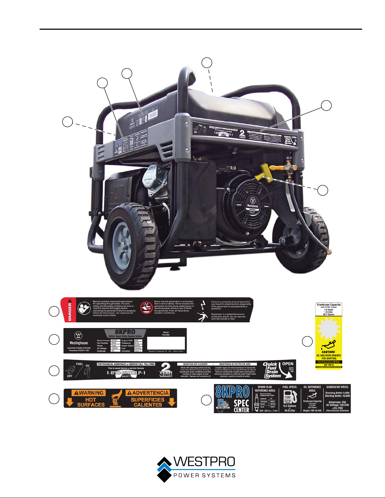
SAFETY LABELS AND DECALS – 8KPRO
1
5
2
3
4
1
5
2
3
4
Figure 3
12
Page 13
SAFETY
1
2
6
3
4
5
1
2
3
4
13
6
Figure 4
5
Page 14
UNPACKING
UNPACKING THE
GENERATOR
!
CAUTION
Always have assistance when lifting
the generator. The generator is heavy;
lifting it could cause bodily harm.
Avoid cutting on or near staples to
prevent personal injury.
!
Tools required – box cutter or similar device.
1. Carefully cut the packing tape on top of the carton.
Fold back top flaps to reveal the manual.
2.
3. Remove the Wheel Kit Accessories.
4. Carefully cut two sides of the carton to remove the
generator.
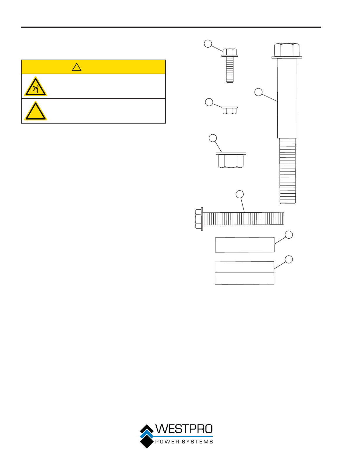
WHEEL KIT ACCESSORIES
If any parts are missing, please locate an authorized
Westinghouse Generator dealer at www.westpropower.
com or call 1-855-WHHELP1 (1-855-944-3571).
1
4
2
3
5
Components:
Wheels (2)
Tool Bag (1)
Spark Plug Socket
Wrench (1)
Battery Charger (1)
Lifting Bracket (1)
0.75 L Bottle of SAE
10W30 Oil – 10KPRO (2)
1.0 L Bottle of SAE
10W30 Oil – 8KPRO (1)
Mounting Foot (1)
Oil Funnel (1)
Remote Start Key Fob (1)
Figure 5 – Hardware
1 - Flange Bolt
M8 x 18 mm
(2 used)
2 - Locking Flange
Nut M8 (4 used)
3 - Serrated Flange
Nut M12 (4 used)
6
7
4 - Wheel Axle Bolt
M12 x 1.5 mm
(2 used)
5 - Hex Bolt M8 x 50
mm (2 used)
6 - Spacer Sleeve
(2 used)
7 - Rubber Sleeve
(2 used)
14
Page 15
ASSEMBLY
ASSEMBLY
Before assembling the generator,
review Safety on page 7 and the
following safety messages.
!
CAUTION
Never lift the generator without
assistance. The generator is heavy and
lifting without assistance could result
in personal injury.
Never use the handles as a lifting
!
Assembling the generator will require lifting the unit.
Make sure all engine oil and fuel are drained from the
unit prior to assembling.
Once assembled, the wheel kit is not intended for
on-road use. The wheel kit is designed for use on this
generator only.
point to support the entire weight of
the generator. Only use the handles
to move the generator by lifting the
handles and using the wheels to move
the generator.
Use caution when collapsing the
handles. Hands and fingers could get
caught and pinched.
NOTICE
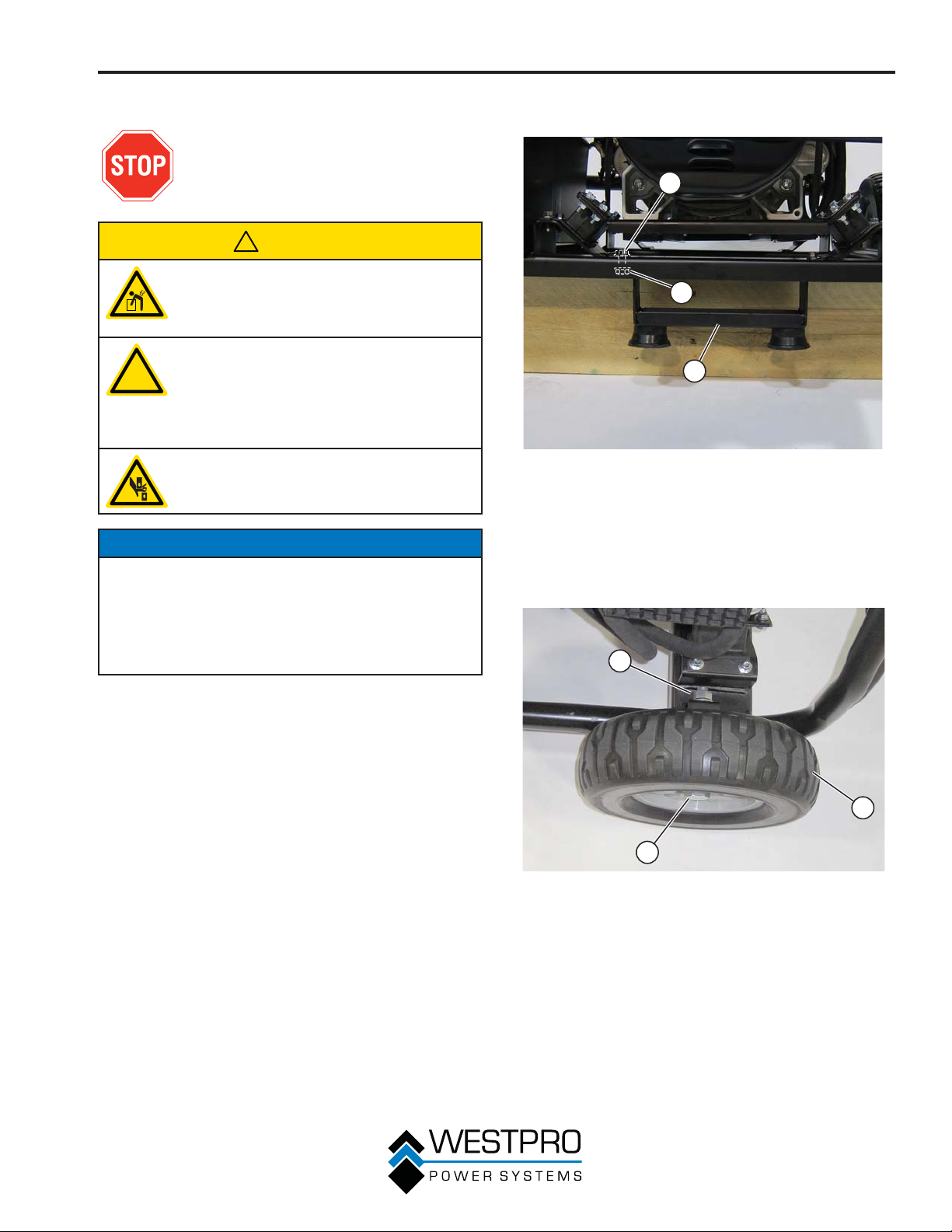
3. Install the mounting foot to the frame using M8
flange bolts and nuts (see Figure 6).
1
2
3
Figure 6 – Assemble Mounting Foot to Frame
1 - M8 Flange Bolt
2 - M8 Flange Nut
4. Install the 12 mm x 1.5 mm axle bolt through the
axle bracket on the frame.
5. Install the flange nut and tighten (see Figure 7).
1
3 - Mounting Foot
Tools required – tool bag (included).
1. Place generator on a flat surface.
2. Using a block of wood, raise and support the back
of the generator.
3
Figure 7 – Assemble Wheels to Frame
1 - Flange Nut
2 - Wheel
3 - Axle Bolt
2
15
Page 16
ASSEMBLY
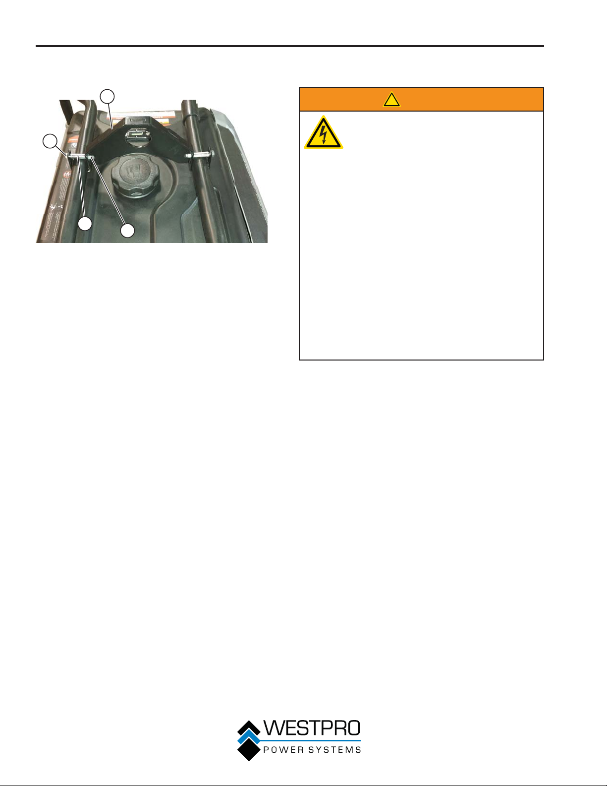
6. Install the lifting bracket using the hex bolts,
spacers and locknuts (see Figure 8).
1
2
3
Figure 8 – Installing Lifting Bracket
1 - Lifting Bracket
2 - Hex Bolt
4
3 - Spacer Sleeve
4 - Locknut
INSTALLING THE BATTERY
!
WARNING
To avoid electric shock:
• ALWAYS connect the positive (+)
battery cable (red boot) first when
connecting battery cables.
• ALWAYS disconnect the negative (-)
battery cable (black boot) first when
disconnecting battery cables.
• NEVER connect the negative (-)
battery cable (black boot) to the
positive (+) post on the battery.
• NEVER connect the positive (+)
battery cable (red boot) to the
negative (-) post on the battery.
• NEVER touch both battery posts
simultaneously.
• NEVER place a metal tool across
both battery posts.
• ALWAYS use insulated or nonconducting tools when installing the
battery.
OTE:N The generator comes equipped with the
positive battery cable (red boot) already
attached.
1. Verify the positive (+) battery cable (red boot) is
securely tightened to the positiv
Make sure boot is over battery post.
2. Carefully remove the protective wrapping around
the lug of the negative (-) battery cable (black boot).
3. Locate negative (-) cable attached to alternator
cable, remove tie and route to the negative (-)
battery post.
e (+) battery post.
16
Page 17
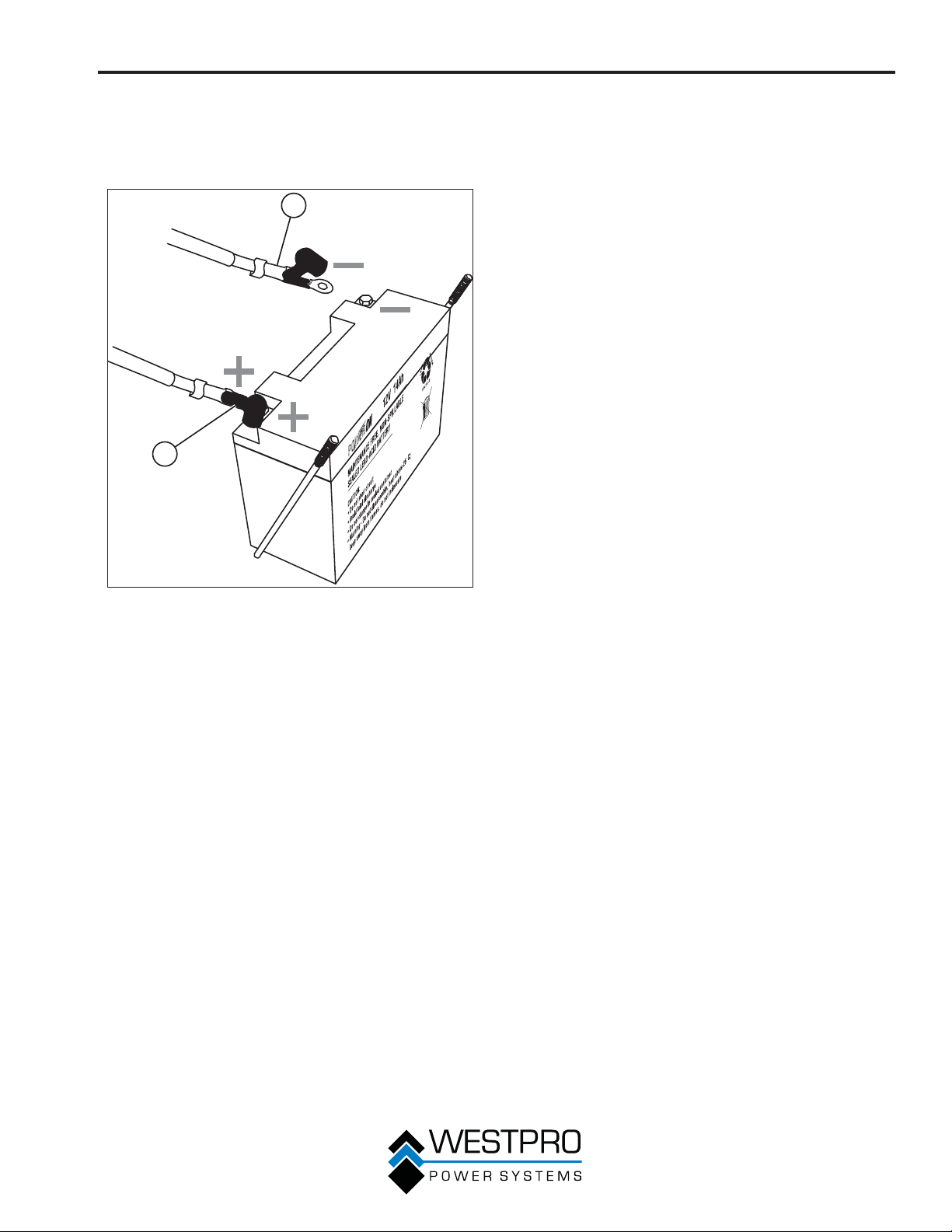
4. Pull back the black boot and securely attach
the negative (-) battery cable (black boot) to the
negative (-) battery post as shown in Figure 9.
Replace the black boot so it protects the cable lug
and battery post.
2
1
ASSEMBLY
Figure 9 – Attaching the Negative (-) Battery Cable
(Black)
1 - Positive (+)
Battery Cable
(Red)
2 - Negative (-)
Battery Cable
(Black)
17
Page 18
FEATURES
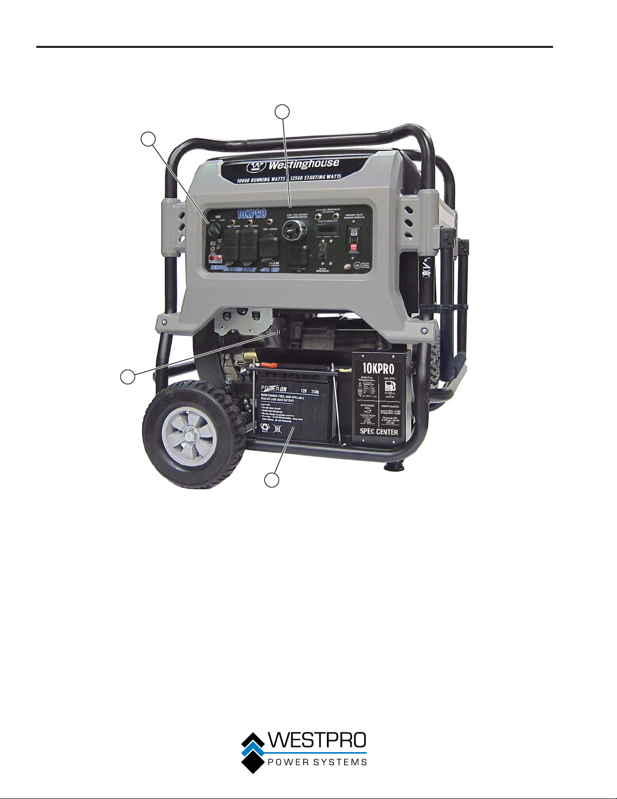
GENERAL GENERATOR FEATURES – 10KPRO
2
1
4
1 - Engine Control Switch: Turns the engine on
and off.
2 - Control Panel: Contains the circuit breakers
and outlets.
3
Figure 10
3 - Battery: Used for starting the generator.
4 - Oil Dipstick: Remove the dipstick to check
the engine oil.
18
Page 19
FEATURES
1
2
3
4
7
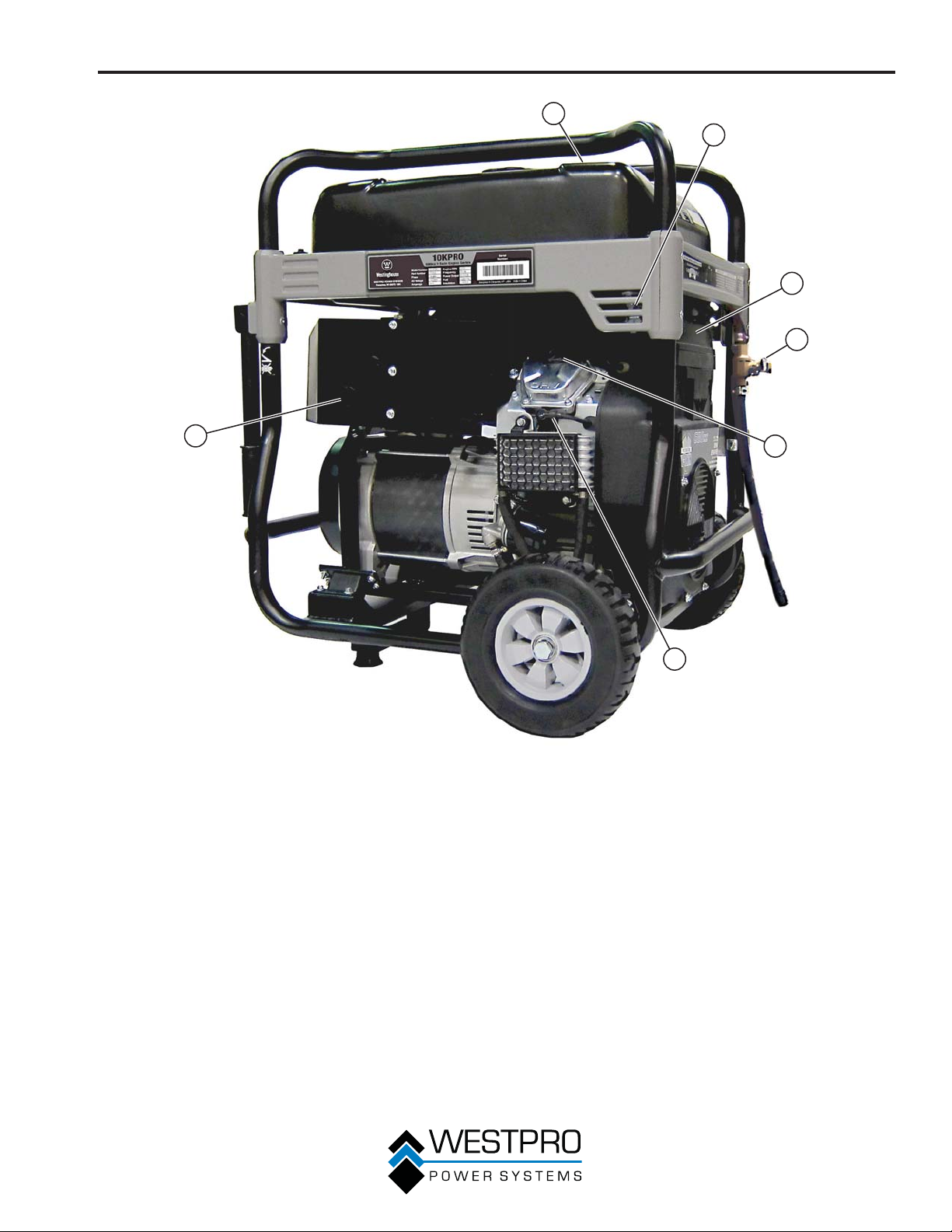
1 - Fuel Gauge: Indicates fuel level.
2 - Fuel Shutoff Valve: Controls the flow of fuel
to the engine.
3 - Air Cleaner Cover: Must remove to service
the air cleaner.
4 - Quick Drain Valve: Use to drain
contaminants from the fuel tank.
5
6
Figure 11
5 - Oil Fill Cap: Remove to add engine oil.
6 - Spark Plug Boot (Wire): Must be removed
when servicing the engine or the spark plug.
7 - Muffler: Avoid contact until the engine is
cooled down.
19
Page 20
FEATURES
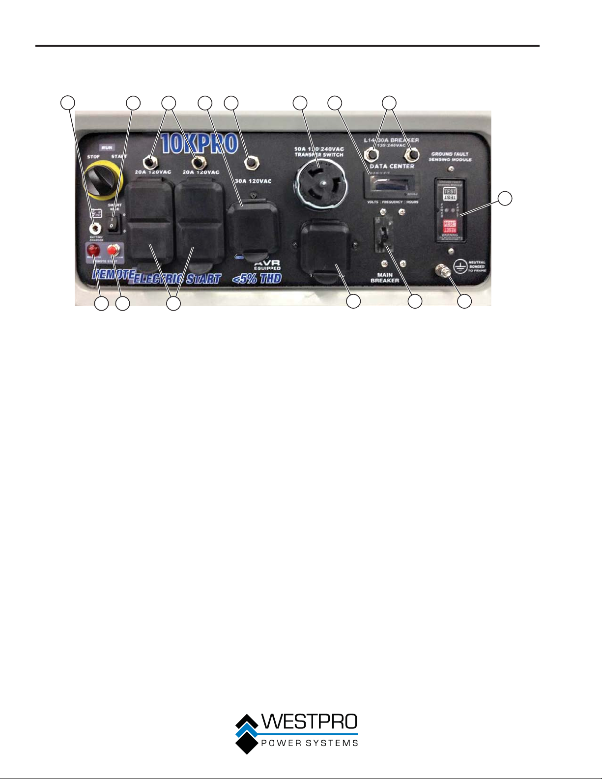
CONTROL PANEL FEATURES – 10KPRO
1
1 - Battery Charger Port: Plug the 120-volt
AC charger into this port to charge the
generator battery.
2 - Low Idle Control: With the smart idle switch
in the ON (I) position, if there is no load
present to any of the outlets for 5 seconds
or longer, the engine speed will reduce to
1800 RPM. If a load is applied to any of the
outlets, the engine speed will automatically
increase to 3600 RPM. With the smart idle
control in the OFF (O) position, the engine
will constantly run at 3600 RPM.
3 - 20-Amp Circuit Breakers: Each circuit
breaker limits the current that can be
delivered through the 120-volt duplex outlets
to 20 amps.
4 - 120-Volt, 30-Amp Twist Lock Outlet: The
outlet can supply 120V output up to 30 amps.
5 - 120-Volt, 30-Amp Circuit Breakers: The
circuit breaker limits the current that can be
delivered through the 120-volt outlet to 30
amps.
6 - 120/240-Volt, 50-Amp Twist Lock Outlet:
Outlet can supply either 120V or 240V output.
7 - Data Center: The data center displays
voltage, frequency and accumulated run
time.
2
1415 13
3 54
Figure 12 – Control Panel Features
6 7 8
9
1112 10
8 - 120/240-Volt, 30-Amp Circuit Breakers:
The circuit breakers limit the current that can
be delivered through the 120/240-volt outlet
to 30 amps.
9 - Ground Fault Sensor: The sensor will
scan all the outlets on the control panel for
a ground fault. If a ground fault is detected
from any of the outlets, the sensor will
automatically trip the main circuit breaker.
10 - Ground Terminal: The ground terminal is
used to ground the generator.
11 - Main Circuit Breaker: The main circuit
breaker controls total output of all outlets to
protect the generator.
12 - 120/240-Volt, 30-Amp Twist Lock Outlet
(NEMA L14-30): The outlet can supply
either 120V or 240V output up to 30 amps.
13 - 120-Volt, 20-Amp Duplex Outlets: Each
outlet is capable of carrying a maximum of
20 amps on a single outlet or a combination
of all outlets.
14 - Remote Start Program Button: Use this
button along with the key fob to program the
generator to be started remotely.
15 - Remote Start Indicator Light: The light will
light or flash depending on the status of the
remote start system.
20
Page 21
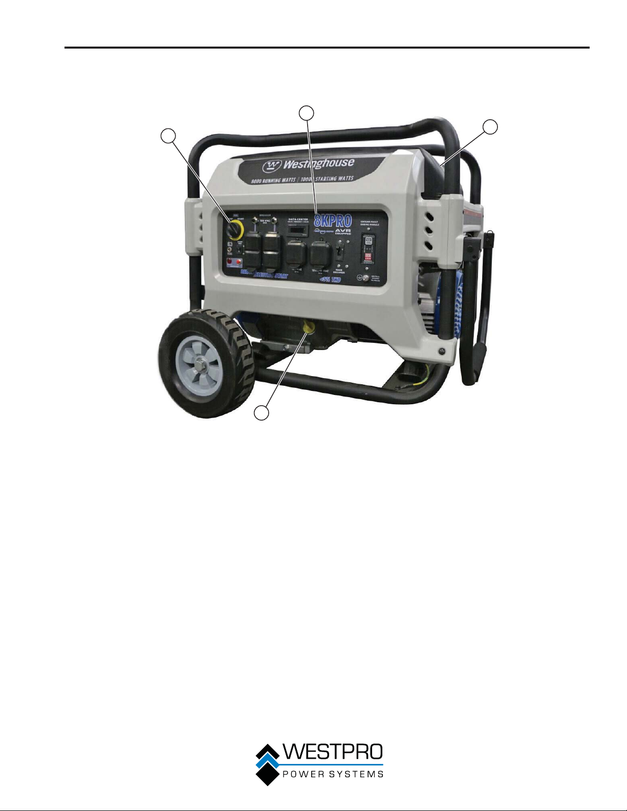
GENERAL GENERATOR FEATURES – 8KPRO
2
1
FEATURES
4
3
1 - Engine Control Switch: Turns the engine on
and off.
2 - Control Panel: Contains the circuit breakers
and outlets.
Figure 13
3 - Oil Fill Plug/Dipstick: Must be removed to
add and check oil.
4 - Fuel Gauge: Indicates fuel level.
21
Page 22
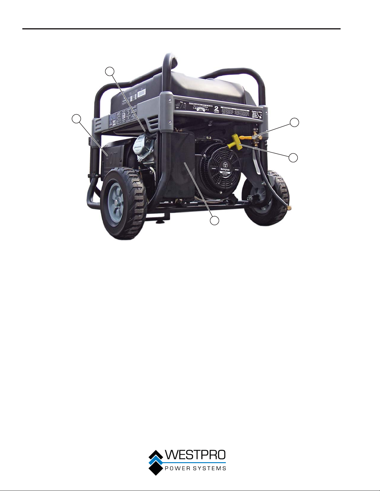
FEATURES
2
1
1 - Muffler: Avoid contact until the engine is
cooled down.
2 - Spark Plug Boot (Wire): Must be removed
when servicing the engine or the spark plug.
3 - Quick Drain Valve: Use to drain
contaminants from the fuel tank.
3
4
5
Figure 14
4 - Recoil Handle: Used to start the generator
manually.
5 - Air Cleaner Cover: Must remove to service
the air cleaner.
22
Page 23
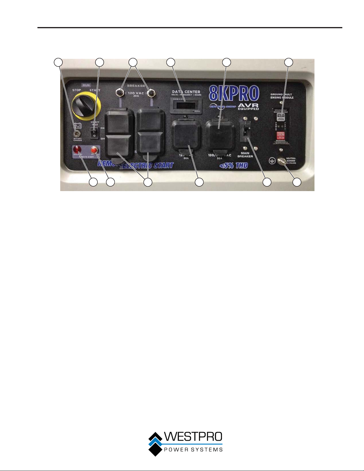
CONTROL PANEL FEATURES – 8KPRO
FEATURES
1
1 - Battery Charger Port: Plug the 120-volt
AC charger into this port to charge the
generator battery.
2 - Low Idle Control: With the smart idle switch
in the ON (I) position, if there is no load
present to any of the outlets for 5 seconds
or longer, the engine speed will reduce to
1800 RPM. If a load is applied to any of the
outlets, the engine speed will automatically
increase to 3600 RPM. With the smart idle
control in the OFF (O) position, the engine
will constantly run at 3600 RPM.
3 - 20-Amp Circuit Breakers: Each circuit
breaker limits the current that can be
delivered through the 120-volt duplex outlets
to 20 amps.
4 - Data Center: The data center displays
voltage, frequency and accumulated run
time.
5 - 120/240-Volt, 30-Amp Twist Lock Outlet
(NEMA L14-30): The outlet can supply
either 120V or 240V output up to 30 amps.
2
12 11
3 4 5 6
10
Figure 15 – Control Panel Features
89 7
6 - Ground Fault Sensor: The sensor will
scan all the outlets on the control panel for
a ground fault. If a ground fault is detected
from any of the outlets, the sensor will
automatically trip the main circuit breaker.
7 - Ground Terminal: The ground terminal is
used to ground the generator.
8 - Main Circuit Breaker: The main circuit
breaker controls total output of all outlets to
protect the generator.
9 - 120-Volt, 30-Amp Twist Lock Outlet: The
outlet can supply 120V output up to 30 amps.
10 - 120-Volt, 20-Amp Duplex Outlets: Each
outlet is capable of carrying a maximum of
20 amps on a single outlet or a combination
of all outlets.
11 - Remote Start Program Button: Use this
button along with the key fob to program the
generator to be started remotely.
12 - Remote Start Indicator Light: The light will
light or flash depending on the status of the
remote start system.
23
Page 24
OPERATION
BEFORE STARTING THE
GENERATOR
Before starting the generator, review
Safety on page 7.
Location Selection – Before starting the generator,
avoid exhaust and location hazards by verifying:
x You have selected a location to operate the
generator that is outdoors and well ventilated.
x You have selected a location with a level and solid
surface on which to place the generator.
x You have selected a location that is at least 6 feet
(1.8 m) away from any building, other equipment or
combustible material.
x If the generator is located close to a building, make
sure it is not located near any windows, doors
and/or vents.
No Connected Loads – Make sure the generator
has no connected loads before starting it. To ensure
there are no connected loads, unplug any electrical
extension cords that are plugged into the control panel
receptacles.
NOTICE
Starting the generator with loads already applied
to it could result in damage to any appliance being
powered off the generator during the brief start-up
period.
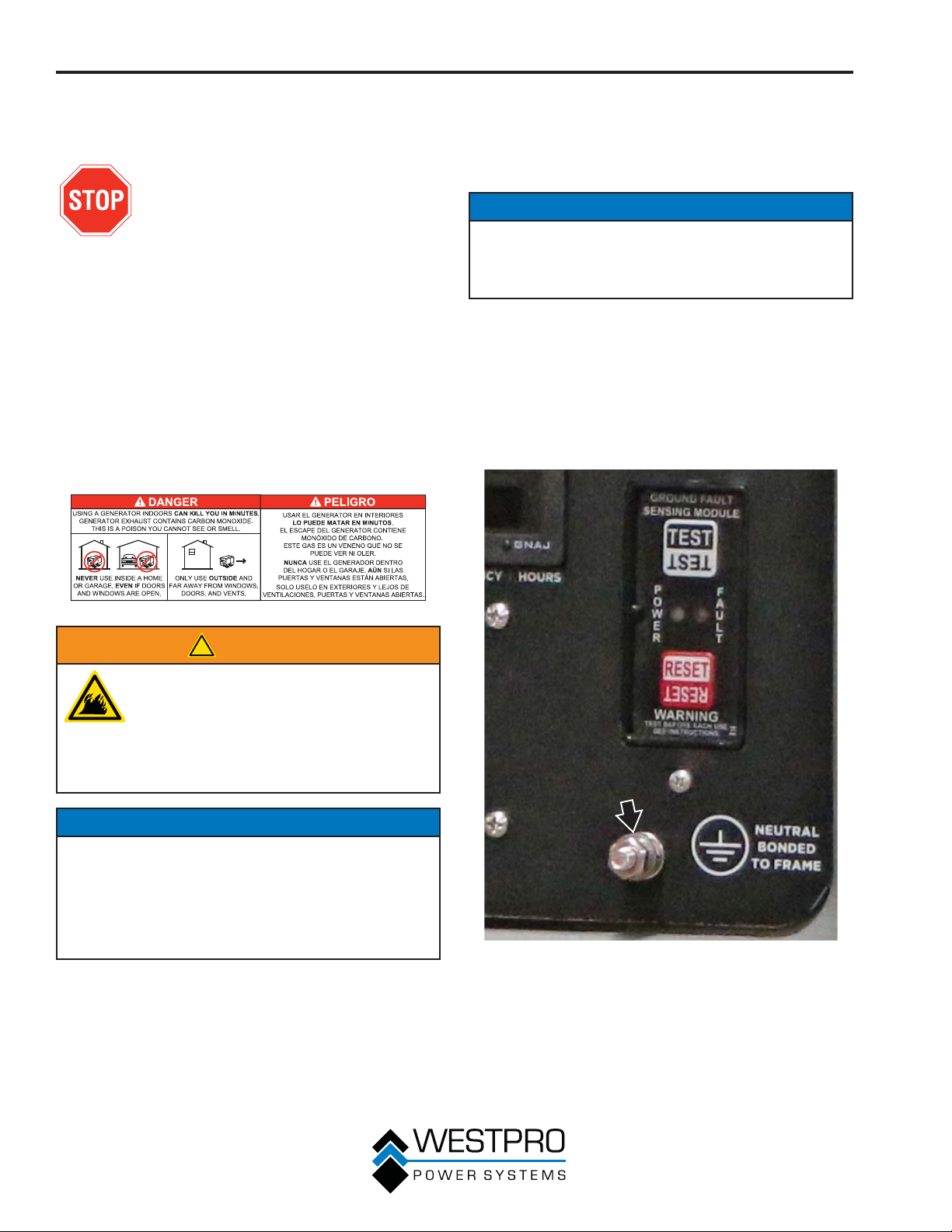
Grounding the Generator – The National Electric
Code (NEC), as well as many local electrical codes,
require the generator to be connected to earth ground
before operating. Before starting the generator, make
sure it is connected to earth ground by connecting
the ground terminal on the control panel (see Figure
16) to earth ground using copper wire (minimum 10
AWG). Consult a qualified electrician for local grounding
requirements.
!
WARNING
Always operate the generator on a level
surface. Placing the generator on nonlevel surfaces can cause the generator
to tip over, causing fuel and oil to spill.
Spilled fuel can ignite if it comes in
contact with an ignition source such as
a very hot surface.
NOTICE
Only operate the generator on a solid, level surface.
Operating the generator on a surface with loose
material such as sand or grass clippings can cause
debris to be ingested by the generator that could:
• Block cooling vents
• Block air intake system
Weather – Never operate your generator outdoors
during rain, snow or any combination of weather
conditions that could lead to moisture collecting on, in
or around the generator.
Dry Surface – Always operate the generator on a dry
surface free of any moisture.
Figure 16 – Ground Terminal on the Control Panel
24
Page 25
!
WARNING
Be sure the generator is properly
connected to earth ground before
operating. The generator must be
grounded to prevent electrical shock
due to faulty appliances.
POWER CORD
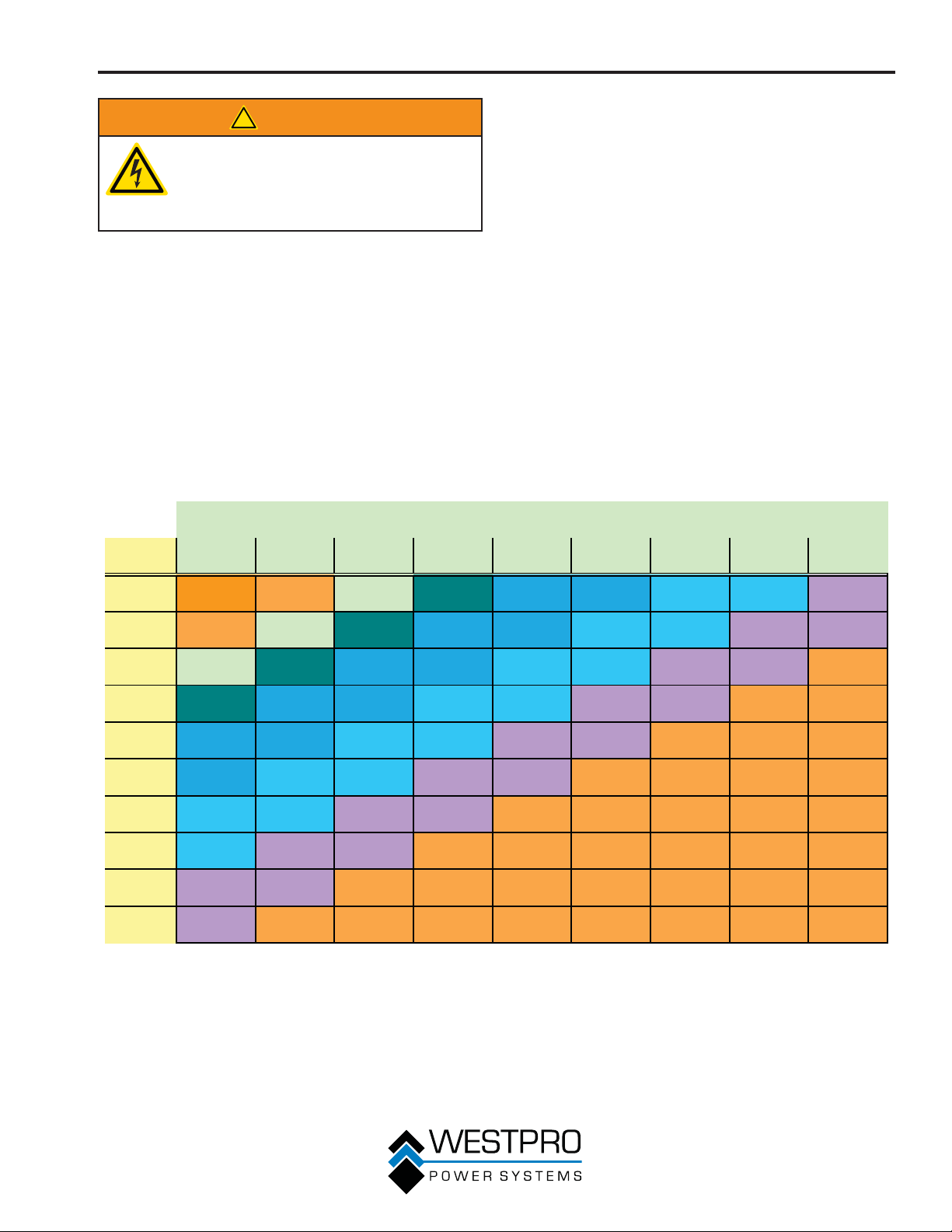
Using Extension Cords
Westpro Power Systems assumes no responsibility for
the content within this table. The use of this table is the
responsibility of the user only. This table is intended
for reference only. The results produced by using this
table are not guaranteed to be correct or applicable in
all situations as the type and construction of cords are
highly variable. Always check with local regulations and
a licensed electrician prior to installing or connecting an
electrical appliance.
Extension Cord Wire Gauge Size
OPERATION
Length of Extension Cord (ft)
Amps10203040506080100120
5 20 18 16 14 12 12 10 10 8
10 18 16 14 12 12 10 10 88
15 16 14 12 12 10 10 8 8 6
20 14 12 12 10 10 8866
25 1212101088666
30 121010886666
35 10108866666
40 1088666---
45 88666----
50 8666-----
25
Page 26
OPERATION
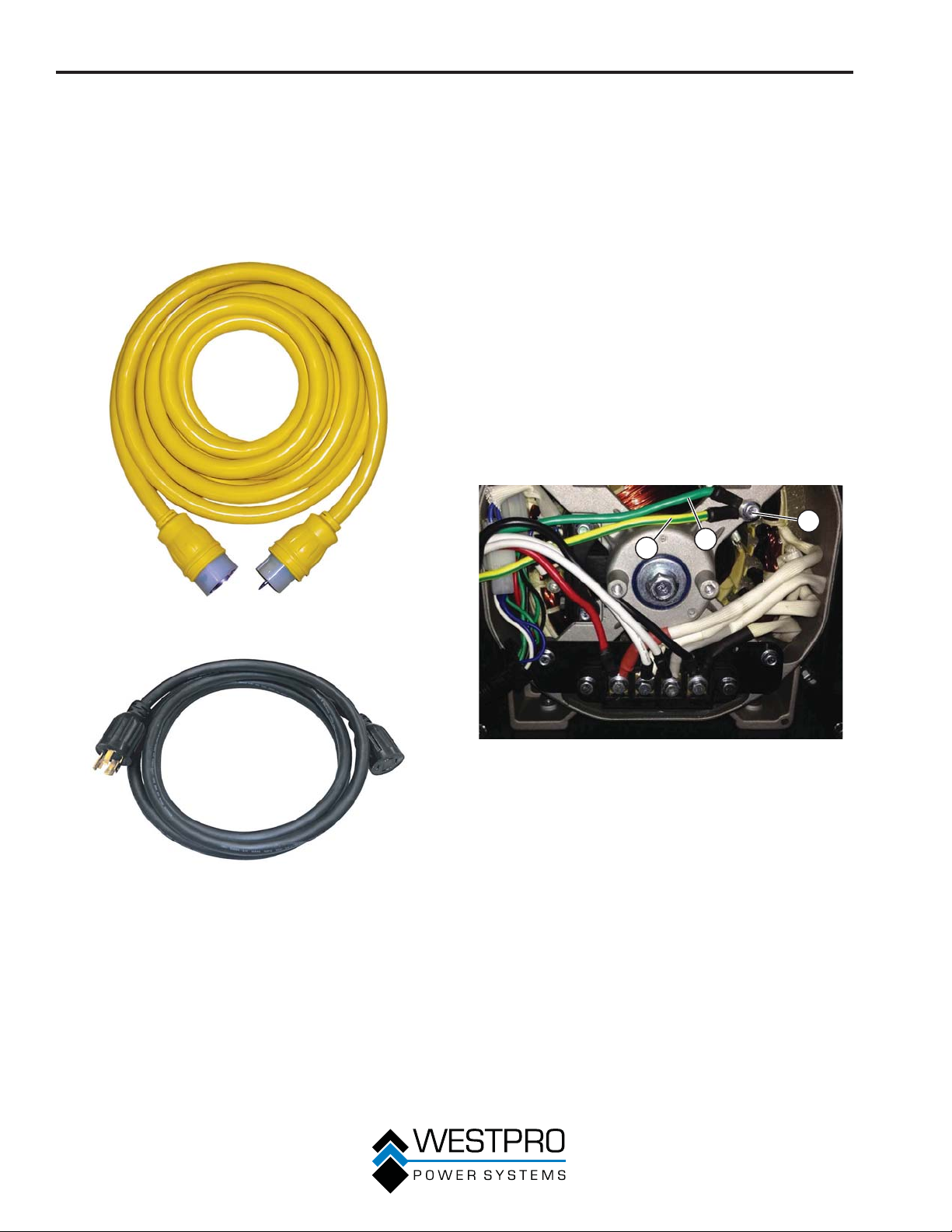
Transfer Switch Cord
The transfer switch cord, 10KPRO Part No. 210051 and
8KPRO Part No. 210075, is an optional accessory for
the portable generator. It is used to connect the 50-amp
outlet on the 10KPRO and the 30-amp outlet on the
8KPRO of the generator to the transfer switch. If your
transfer switch does not come with a transfer switch
cord, order the cord from Westpro Power.
TRANSFER SWITCH
CONNECTIONS
The Westinghouse generator is wired with the neutral
bonded to ground. If you are connecting your generator
to a transfer switch, the electrician must first determine
what type transfer switch is being used. Transfer
switches for this equipment are either two-pole or threepole types.
A two-pole transfer switch will not switch the neutral
from the generator to the service panel. That means
the generator will be grounded to the service panel. To
use the generator with two-pole transfer switches, the
electrician will need to change the neutral from bonded
to floating.
Remove the ground screw from the wires (see Figure
19). Wrap the terminal end of the green wire with
electrical tape so it is insulated. Tape the green wire to
the yellow/green wire so it cannot contact any moving
parts. Connect the yellow/green wire back to ground
using the ground screw.
1
3
2
Figure 17 – Transfer Switch Cord, 10KPRO
Figure 18 – Transfer Switch Cord, 8KPRO
Figure 19 – Bonding Wire
1 - Ground Screw
2 - Green Wire
3 - Yellow/Green
Wire
26
Page 27
OPERATION
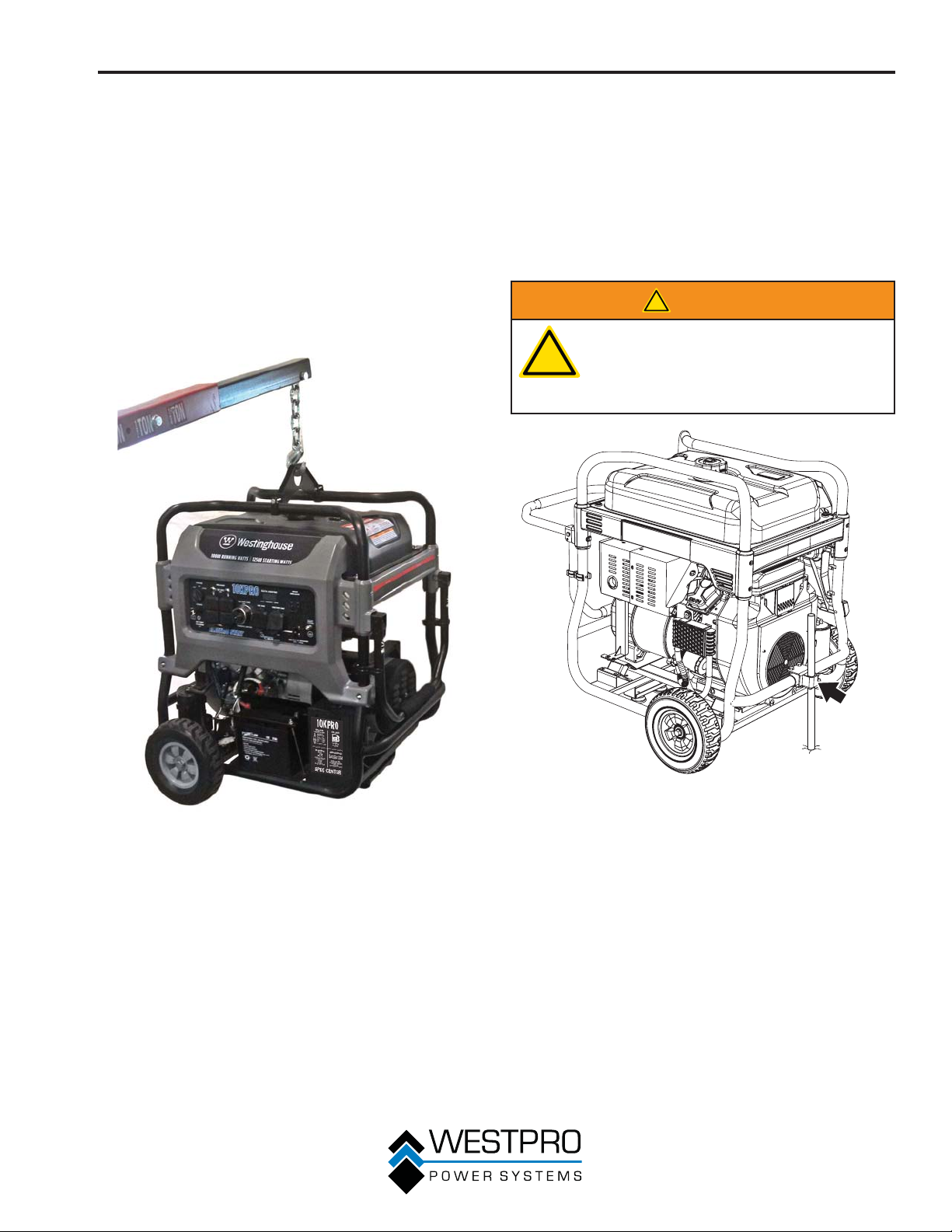
LIFTING BRACKET
1. Before lifting the generator, inspect the bracket and
make sure it is securely fastened to the generator.
Do not lift the generator unless the lifting bracket is
securely fastened.
2. Hook a chain or strap through the eye on the lifting
bracket and make sure it is securely fastened.
3. Connect a suitable lifting device to the chain or
strap.
4. Lift the generator slightly to ensure it is lifting
straight and level. Adjust the bracket if required to
allow it to lift correctly.
GENERATOR ANCHOR
The generator should be used on a flat, level surface
whenever possible. If the particular job site requires the
generator to be used on uneven terrain, the generator
should be anchored. Insert a stake or piece of rebar
through the anchor bracket on the frame (see Figure
21). Drive the stake into the ground to secure the
generator and prevent it from moving. The anchor is
standard on 10KPRO and optional on 8KPRO.
!
WARNING
Anchoring the generator to the
!
ground does not electrically ground
the generator. For proper electrical
grounding of the generator, see
Grounding the Generator on page 24.
Figure 21 – Anchor Bracket
Figure 20 – Lifting Bracket
27
Page 28
OPERATION
ADDING / CHECKING ENGINE
FLUIDS AND FUEL
Before adding/checking engine
fluids and fuel, review Safety on
page 7.
!
DANGER
Filling the fuel tank with gasoline while
the generator is running can cause
gasoline to leak and come in contact
with hot surfaces that can ignite the
gasoline.
Before starting the generator, always check the level of:
x Engine oil
x Gasoline in the fuel tank
Once the generator is started and the engine gets
warm, it is not safe to add gasoline to the fuel tank or
engine oil to the engine while the engine is running or
the engine and muffler are hot.
Checking and / or Adding Engine Oil
!
WARNING
Internal pressure can build in the
engine crankcase while the engine
is running. Removing the oil dipstick
while the engine is hot can cause
extremely hot oil to spray out of the
crankcase and can severely burn skin.
Allow engine oil to cool for several
minutes before removing the oil
dipstick.
Adding Gasoline to the Fuel Tank
!
WARNING
Never refuel the generator while the
engine is running.
Always turn the engine off and allow
the generator to cool before refueling.
Required Gasoline – Only use gasoline that meets the
following requirements:
x Unleaded gasoline only
x Gasoline with maximum 10% ethanol added
x Gasoline with an 87 octane rating or higher
Filling the Fuel Tank – Follow the steps below to fill the
fuel tank:
1. Shut off the generator.
2. Allow the generator to cool down so all surface
areas of the muffler and engine are cool to the
touch.
3. Move the generator to a flat surface.
4. Clean area around the fuel cap.
5. Remove the fuel cap by rotating counterclockwise.
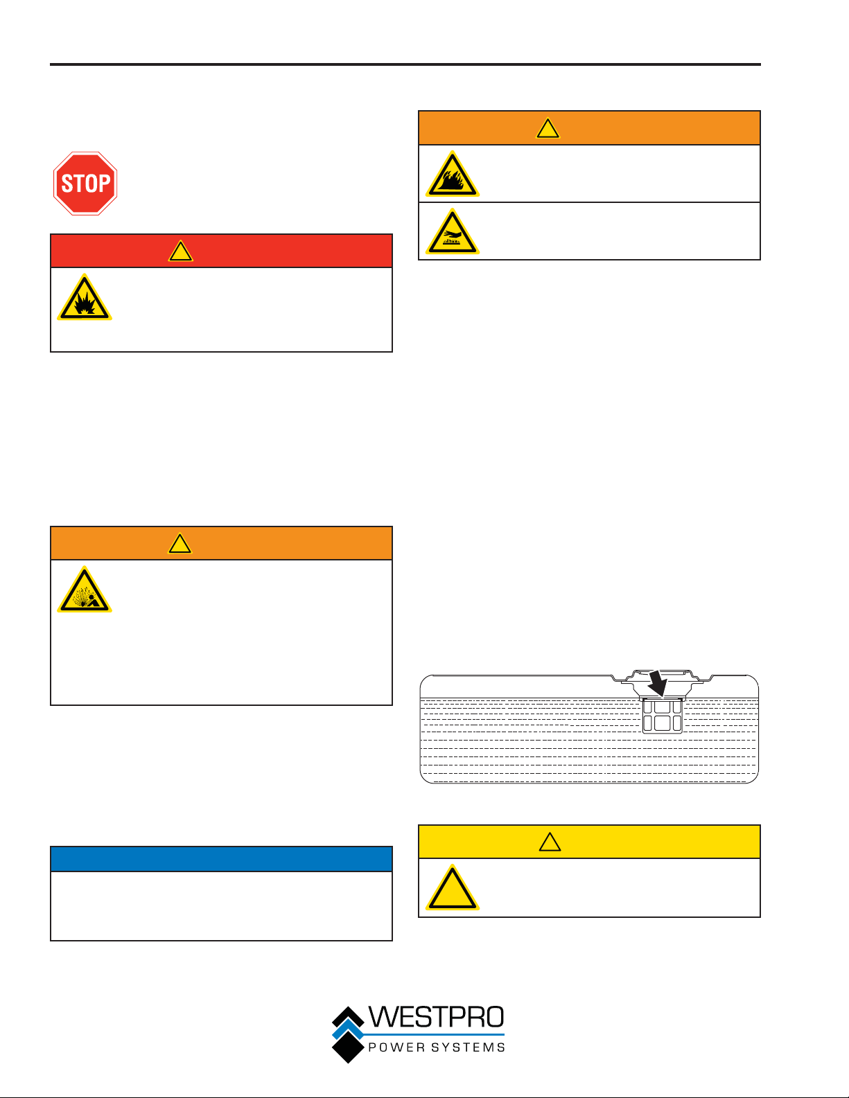
6. Slowly add gasoline into the fuel tank. Be very
careful not to overfill the tank. The gasoline level
should NOT be higher than the bottom of the filler
neck (see Figure 22).
7. Install the fuel cap by rotating clockwise until
you hear a click, indicating the cap is completely
installed.
The unit as shipped does not contain oil in the
engine. You must add engine oil before starting the
generator for the first time. See Checking Engine
Oil – 10KPRO on page 35, Checking Engine Oil –
8KPRO on page 36, Adding Engine Oil – 10KPRO
on page 36 and Adding Engine Oil – 8KPRO on
page 37 for instructions on checking engine oil
level and the procedure for adding engine oil.
NOTICE
The generator does not contain engine oil as shipped.
Attempting to start the engine without adding
engine oil can permanently damage internal engine
components.
28
Figure 22 – Maximum Gasoline Fill Level
!
CAUTION
Avoid prolonged skin contact with
!
gasoline. Avoid prolonged breathing of
gasoline vapors.
Page 29
OPERATION
PROGRAMMING THE
GENERATOR FOR REMOTE
START
!
WARNING
Always make sure the area around the
generator is clear of bystanders before
using the remote start to start the
generator.
The generator can be started remotely from up to a
maximum of 109 yards (100 M) away using the remote
start key fob with new, fully charged batteries in the
key fob. As the batteries’ state of charge in the key fob
reduces, the distance to start the generator will also
reduce.
Before the generator can be started, an initial start-up
procedure must be performed so the generator and the
key fob recognize each other. If the key fob is replaced,
you will need to go through this procedure with the new
fob.
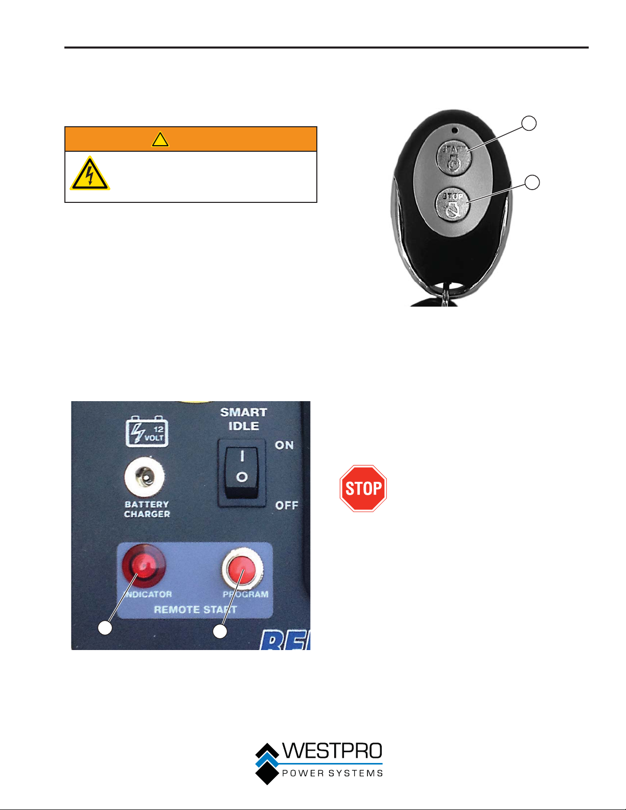
1. Turn the engine control switch to the RUN position.
Push and hold the program button on the control
2.
panel (see Figure 23) for 3 seconds. The remote
start indicator light will light.
3. Press the stop button on the remote start key fob
(see Figure 24).
and then remain lit.
Figure 24 – Remote Start Key Fob
1 - Start Button 2 - Stop Button
4. Press the start button on the remote start key fob.
The indicator light will flash once and then remain
lit.
Press and hold the program button for 3 seconds.
5.
The indicator light will now turn off after 3 seconds.
The generator is now programmed to start remotely.
The indicator light will flash once
1
2
1
Figure 23 – Remote Start Programming
1 - Remote Start
Indicator Light
2
2 - Remote Start
Program Button
STARTING THE GENERATOR
Before starting the generator, review
Safety on page 7.
Before attempting to start the generator, verify the
following:
x The engine is filled with engine oil (see Checking
Engine Oil – 10KPRO on page 35 and Checking
Engine Oil – 8KPRO on page 36).
x The generator is situated in a proper location (see
Location Selection on page 24).
x The generator is on a dry surface (see Weather and
Dry Surface on page 24).
x All loads are disconnected from the generator (see
No Connected Loads on page 24).
x The generator is properly grounded (see Grounding
the Generator on page 24).
x The ground fault sensor is working correctly (see
Testing the Ground Fault Sensor on page 46).
29
Page 30
OPERATION
!
DANGER
Never use the generator in a location
that is wet or damp. Never expose the
generator to rain, snow, water spray or
standing water while in use. Protect the
generator from all hazardous weather
conditions. Moisture or ice can cause a
short circuit or other malfunction in the
electrical circuit.
Never operate the generator in an
enclosed area. Engine exhaust
contains carbon monoxide. Only
operate the generator outside and away
from windows, doors and vents.
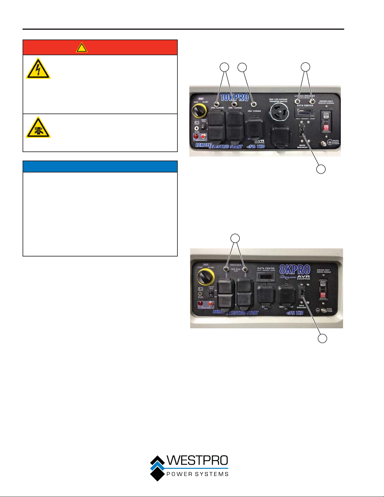
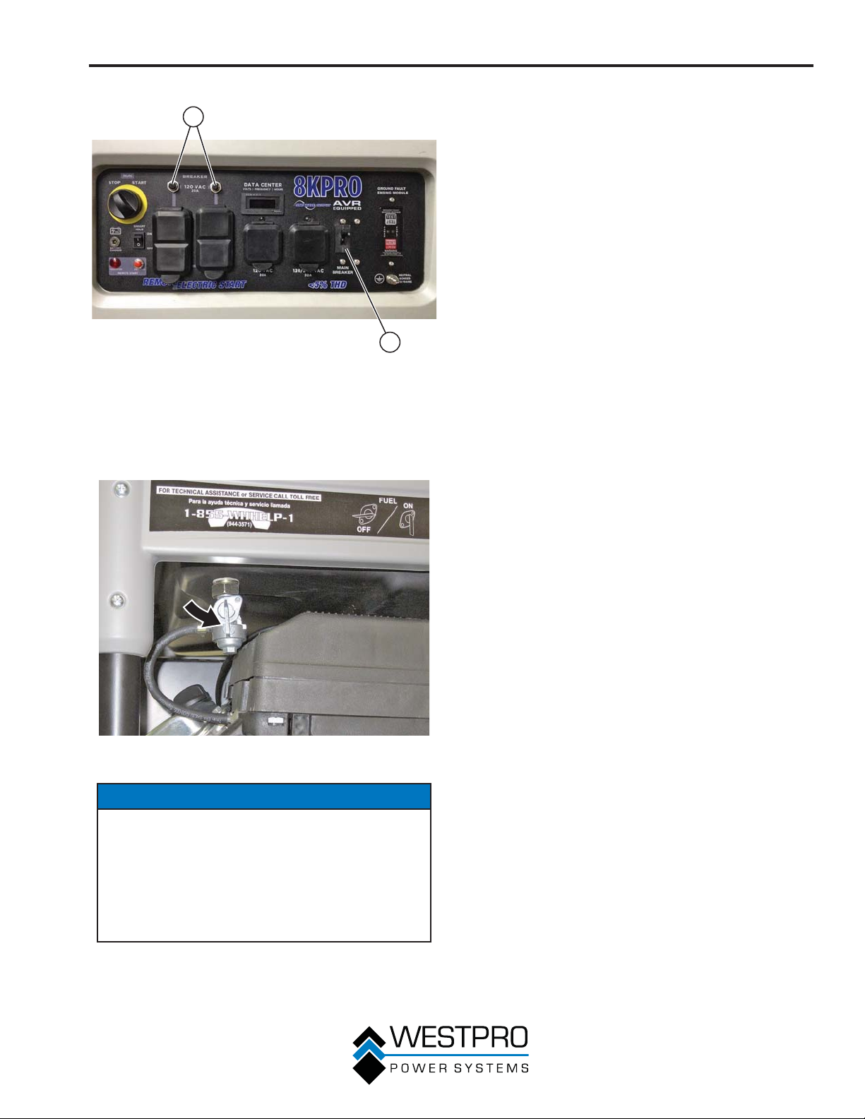
2. Make sure the circuit breakers are properly set (see
Figure 25 and Figure 26).
1
2
3
NOTICE
The engine is equipped with a low oil shutdown
switch. If the oil level becomes low, the engine will
shut down and will not start until the oil is filled to the
proper level.
Be sure the engine has the proper oil level before
using. Failure to verify that the engine has the proper
oil level could result in engine damage.
Disconnect all loads from the generator before
starting. Failure to verify all loads are disconnected
prior to starting the generator could result in damage
to the connected appliances.
1. Verify the battery is properly installed and both
battery cables are attached (see Installing the
Battery on page 16).
Figure 25 – Circuit Breakers – 10KPRO
1 - 120V Circuit
Breaker
2 - 120V 30-Amp
Circuit Breaker
1
3 - 120/240V
30-Amp Circuit
Breaker
4 - Main Breaker
4
2
30
Figure 26 – Circuit Breakers – 8KPRO
1 - 120V Circuit
Breaker
2 - Main Breaker
Page 31
OPERATION
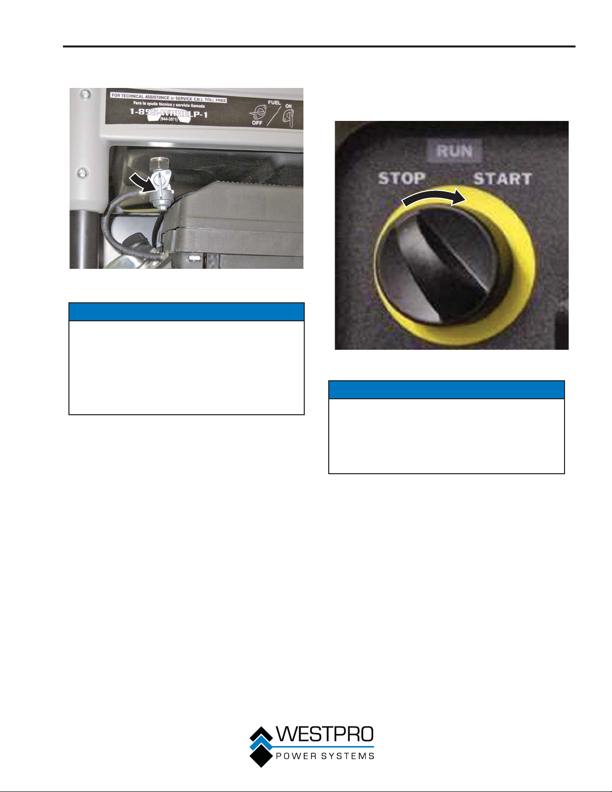
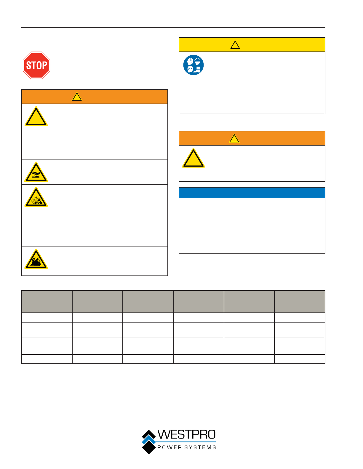
3. Move the fuel shutoff valve to the ON position (see
Figure 27).
Figure 27 – Fuel Shutoff Valve in the ON Position
NOTICE
This generator is equipped with an automatic
choke for starting. This system is always on and
cannot be turned off. Do not attempt to make
adjustments to the automatic choke or any other
carburetor adjustments. Tampering with the
automatic choke system may void your warranty.
See an authorized Westinghouse service center for
more information.
4. Turn the engine control switch to the ST
position until the engine starts. Once the engine
starts, release the engine control switch; the switch
will automatically move into the ON position (see
Figure 28).
Figure 28 – Engine Control Switch
ART
NOTICE
Failure to release the engine control switch once
the engine starts could result in damage to the
generator.
Never turn the engine control switch to the START
position while the engine is running; this could
damage the generator.
OTE:N If the engine fails to start after 5 seconds,
release the engine control switch. Let the
generator sit idle for 15 seconds and then
repeat step 4. If the cranking speed drops
after each unsuccessful attempt, then the
battery may not be adequately charged.
OTE:N The generator is equipped with a battery
charging feature. Once the engine is
running, a small charge is supplied to
the battery via the battery cables and will
slowly recharge the battery.
31
Page 32
OPERATION
STOPPING THE GENERATOR
Normal Operation
During normal operation, use the following steps to stop
your generator:
1. Remove any connected loads from the control
panel receptacles.
2. Allow the generator to run at “no load” to reduce
and stabilize engine and alternator temperatures.
3. Turn the engine control switch to the OFF position.
4. Turn the fuel shutoff valve to the OFF position.
During an Emergency
If there is an emergency and the generator must be
stopped quickly, push the engine control switch to the
OFF position immediately.
STARTING THE GENERATOR
USING REMOTE START
Before starting the generator, review
Safety on page 7.
Before attempting to start the generator, verify the
following:
x The engine is filled with engine oil (see Checking
Engine Oil – 10KPRO on page 35 and Checking
Engine Oil – 8KPRO on page 36).
x The generator is situated in a proper location (see
Location Selection on page 24).
x The generator is on a dry surface (see Weather and
Dry Surface on page 24).
x All loads are disconnected from the generator (see
No Connected Loads on page 24).
x The generator is properly grounded (see Grounding
the Generator on page 24).
x The ground fault sensor is working correctly (see
Testing the Ground Fault Sensor on page 46).
!
DANGER
Never operate the generator in an
enclosed area. Engine exhaust
contains carbon monoxide. Only
operate the generator outside and away
from windows, doors and vents.
NOTICE
The engine is equipped with a low oil shutdown
switch. If the oil level becomes low, the engine will
shut down and will not start until the oil is filled to the
proper level.
Be sure the engine has the proper oil level before
using. Failure to verify that the engine has the proper
oil level could result in engine damage.
Disconnect all loads from the generator before
starting. Failure to verify all loads are disconnected
prior to starting the generator could result in damage
to the connected appliances.
1. Verify the battery is properly installed and both
y cables are attached (see Installing the
batter
Battery on page 16).
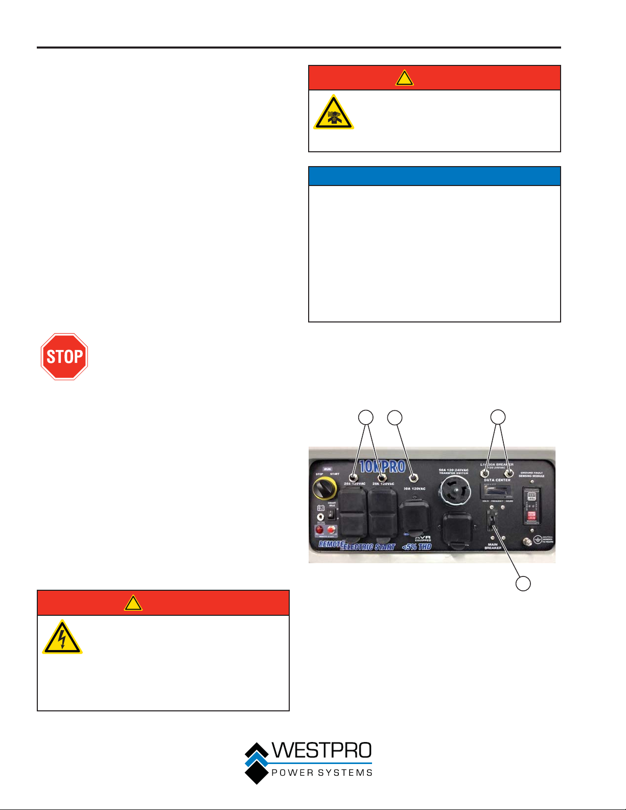
2. Make sure the circuit breakers are properly set (see
Figure 29 and Figure 30).
1
2
3
4
32
!
DANGER
Never use the generator in a location
that is wet or damp. Never expose the
generator to rain, snow, water spray or
standing water while in use. Protect the
generator from all hazardous weather
conditions. Moisture or ice can cause a
short circuit or other malfunction in the
electrical circuit.
Figure 29 – Circuit Breakers – 10KPRO
1 - 120V Circuit
Breaker
2 - 120V 30-Amp
Circuit Breaker
3 - 240/120V
30-Amp Circuit
Breaker
4 - Main Breaker
Page 33
OPERATION
4. Press the start button on the remote start key fob.
1
2
5.
The generator will turn over for 3 to 5 seconds and
start.
6. An engine warmup delay is programmed into the
remote start cycle. After the generator is running,
there will be a delay of electrical output for 15
seconds.
7. If the engine fails to start within 3 to 5 seconds, the
engine will attempt to start five additional times.
If the generator failed to start, the remote start
indicator light will flash.
8. If the generator fails to start after a total of six
attempts, the start button on the key fob must be
pushed again to begin another cycle of six start
attempts.
Figure 30 – Circuit Breakers – 8KPRO
1 - 120V Circuit
Breaker
3. Move the fuel shutoff valve to the ON position (see
Figure 31).
Figure 31 – Fuel Shutoff Valve in the ON Position
2 - Main Breaker
STOPPING THE GENERATOR
USING REMOTE START
1. Make sure there is no load to any of the generator
outlets.
2. Press the stop button on the remote start key fob.
3. The generator will run for an additional 15 seconds
as it goes through a cooldown cycle before shutting
off.
NOTICE
This generator is equipped with an automatic
choke for starting. This system is always on and
cannot be turned off. Do not attempt to make
adjustments to the automatic choke or any other
carburetor adjustments. Tampering with the
automatic choke system may void your warranty.
See an authorized Westinghouse service center for
more information.
33
Page 34
MAINTENANCE
MAINTENANCE
Before performing maintenance
on the generator, review Safety on
page 7 and the following safety
messages.
!
WARNING
Avoid accidentally starting the
!
Table 1: Maintenance Schedule - Owner Performed
Maintenance
Engine Oil
Cooling
Features
Air Filter
Spark Plug
1
Service more frequently if operating in dry and dusty conditions.
generator during maintenance by
removing the spark plug boot from the
spark plug. Also disconnect the battery
cables from the battery (disconnect the
black negative (-) cable first) and place
the cables away from the battery posts
to avoid arcing.
Allow hot components to cool to
the touch prior to performing any
maintenance procedure.
Internal pressure can build in the
engine crankcase while the engine
is running. Removing the oil dipstick
while the engine is hot can cause
extremely hot oil to spray out of the
crankcase and can severely burn skin.
Allow engine oil to cool for several
minutes before removing the oil
dipstick.
Always perform maintenance in a wellventilated area. Gasoline fuel and fuel
vapors are extremely flammable and
can ignite under certain conditions.
After First 20
Hours or First
Month of Use
Item
Before Every
Use
Check Level Change Change – –
Check/Clean ––––
Check –
– – – Check/Clean Replace
Maintenance Schedule
Following the maintenance schedule is important
to keep the generator in good operating condition.
The following is a summary of maintenance items by
periodic maintenance intervals.
After 50 Hours
of Use or Every
!
CAUTION
Avoid skin contact with engine oil or
gasoline. Prolonged skin contact with
engine oil or gasoline can be harmful.
Frequent and prolonged contact with
engine oil may cause skin cancer.
Take protective measures and wear
protective clothing and equipment.
Wash all exposed skin with soap and
water.
!
WARNING
Failure to perform periodic
!
maintenance or not following
maintenance procedures can cause
the generator to malfunction and could
result in death or serious injury.
NOTICE
Periodic maintenance intervals vary depending
on generator operating conditions. Operating the
generator under severe conditions, such as sustained
high-load, high-temperature, or unusually wet or
dusty environments, will require more frequent
periodic maintenance. The intervals listed in the
maintenance schedule should be treated only as a
general guideline.
3 Months
Inspect or
Replace
After 100 Hours
of Use or Every
6 Months
1
– Replace
After 300 Hours
of Use or Every
Year
34
Page 35
MAINTENANCE
Table 2: Maintenance Schedule - Authorized Westinghouse Service Dealer Performed
Maintenance
Item
Valve Clearance
Fuel Filter
Idle Speed
ore Every
Bef
Use
––––Check/Adjust
– – – Check/Clean –
––––Check/Adjust
After First 20
Hours or First
Month of Use
ENGINE OIL MAINTENANCE
Engine Oil Specification
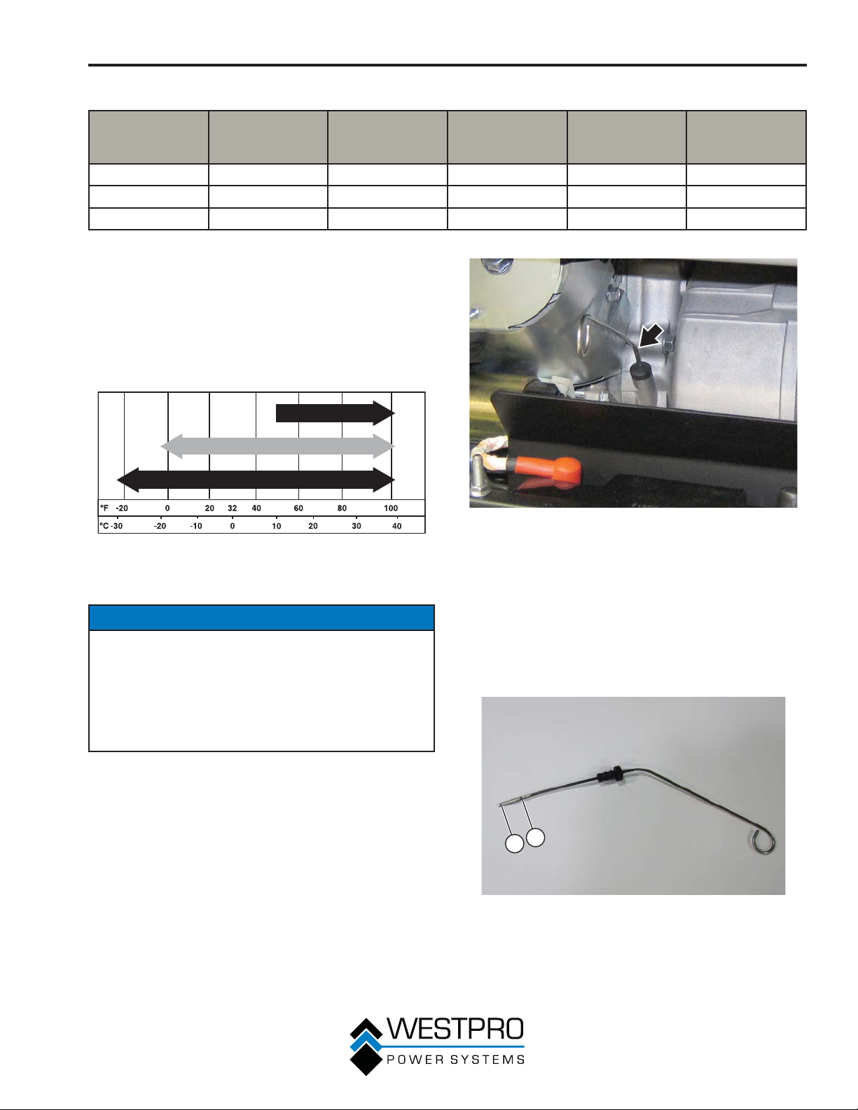
1. Only use the engine oil specified in Figure 32.
2. Only use 4-stroke/cycle engine oil. NEVER
USE 2-STROKE/CYCLE OIL. Synthetic oil is an
acceptable substitute for conventional oil.
SAE 30
Conventional 10W-30
After 50 Hours
of Use or Every
3 Months
After 100 Hours
of Use or Every
6 Months
After 300 Hours
of Use or Every
Year
5W-30
Figure 32 – Recommended Oil
Checking Engine Oil – 10KPRO
NOTICE
Always maintain proper engine oil level. Failure to
maintain proper engine oil level could result in severe
damage to the engine and/or shorten the life of the
engine.
Always use the specified engine oil. Failure to use the
specified engine oil can cause accelerated wear
and/or shorten the life of the engine.
Engine oil level should be checked before every use.
1. Always operate or maintain the generator on a flat
ace.
surf
2. Stop engine if running.
3. Let engine sit and cool for several minutes (allow
crankcase pressure to equalize).
4. With a damp rag, clean around the oil dipstick.
5. Remove oil dipstick (see Figure 33).
Figure 33 – Oil Dipstick
6. Check oil level:
When checking the engine oil, remove the oil
dipstick and wipe it clean. Insert the dipstick all the
way back in and then remove and check the oil level
on the dipstick.
x Acceptable Oil Level – Oil is visible between the
H and L lines on the oil dipstick (see Figure 34).
x Low Oil – Oil is below the L line on the oil dipstick.
2
1
Figure 34 – Checking Oil Level
1 - Low Oil Level
Line
35
2 - High Oil Level
Line
Page 36
MAINTENANCE
Checking Engine Oil – 8KPRO
NOTICE
Always maintain proper engine oil level. Failure to
maintain proper engine oil level could result in severe
damage to the engine and/or shorten the life of the
engine.
Always use the specified engine oil. Failure to use the
specified engine oil can cause accelerated wear
and/or shorten the life of the engine.
Engine oil level should be checked before every use.
1. Always operate or maintain the generator on a flat
surface.
2. Stop engine if running.
3. Let engine sit and cool for several minutes (allow
crankcase pressure to equalize).
4. With a damp rag, clean around the oil fill plug/
dipstick.
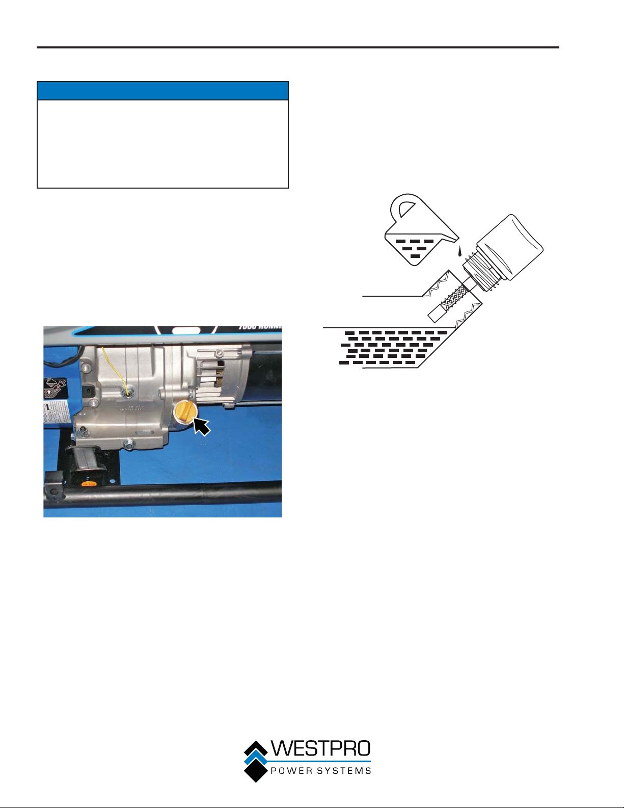
5. Remove oil fill plug/dipstick (see Figure 35).
6. Check oil level:
When checking the engine oil, remove the oil fill
plug/dipstic
plug/dipstick all the way back in and then remove
and check the oil level on the oil fill plug/dipstick.
x Acceptable Oil Level – Oil is visible on the cross-
hatches between the H and L lines on the oil fill
plug/dipstick (see Figure 36).
x Low Oil – Oil is below the L line on the oil fill plug/
dipstick.
k and wipe it clean. Thread the oil fill
H
L
Figure 35 – Oil Fill Plug/Dipstick
Figure 36 – Checking Oil Level
Adding Engine Oil – 10KPRO
1. Always operate or maintain the generator on a flat
surface.
2. Stop engine if running.
3. Let engine sit and cool for several minutes (allow
crankcase pressure to equalize).
4. Thoroughly clean around the oil fill plug.
36
Page 37
MAINTENANCE
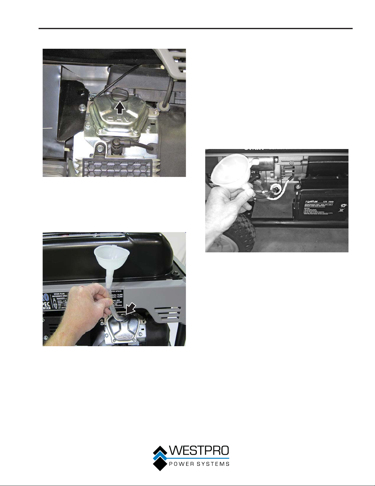
5. Remove oil fill plug (see Figure 37).
Figure 37 – Oil Fill Plug
6. Select the proper engine oil as specified in Figure
32.
7. Using the supplied funnel and tube, slowly add
engine oil to the engine. Stop frequently to check
the level to avoid overfilling (see Figure 38).
Adding Engine Oil – 8KPRO
1. Always operate or maintain the generator on a flat
surface.
2. Stop engine if running.
3. Let engine sit and cool for several minutes (allow
crankcase pressure to equalize).
4. Thoroughly clean around the oil fill plug/dipstick.
5. Remove oil fill plug/dipstick and wipe clean.
6. Select the proper engine oil as specified in Figure
32.
7. Using the supplied funnel and tube, slowly add
engine oil to the engine. Stop frequently to check
the level to avoid overfilling (see Figure 39).
Figure 38 – Adding Engine Oil
8. Continue to add oil until the oil is at the correct
level. See Checking Engine Oil – 10KPRO on page
35.
Figure 39 – Adding Engine Oil
8. Continue to add oil until the oil is at the correct
level. See Checking Engine Oil – 8KPRO on page
36.
Changing Engine Oil – 10KPRO
1. Stop the engine.
2. Let engine sit and cool for several minutes (allow
crankcase pressure to equalize).
3. Place oil pan (or suitable container) under the oil
drain plug and oil filter.
4. With a damp rag, thoroughly clean around the oil
drain plug and oil filter.
5. Turn the oil filter counterclockwise and remove the
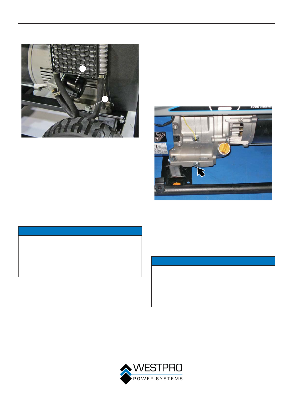
filter (see Figure 40).
37
Page 38
MAINTENANCE
6. Remove the oil drain plug (see Figure 40). Once
removed, place the oil drain plug on a clean surface.
1
2
Figure 40 – Oil Drain Plug and Filter
1 - Oil Filter (Part No.
180389)
7. Allow oil to completely drain.
Replace oil drain plug.
8.
9. Apply a light film of clean engine oil to the rubber
gasket on the oil filter.
10. Install the oil filter by hand-turning clockwise until the
rubber gasket contacts the mounting surface. Turn
the filter an additional half turn. Do not overtighten.
11. Fill crankcase with oil following the steps outlined in
Adding Engine Oil – 10KPRO on page 36.
2 - Oil Drain Plug
NOTICE
Never dispose of used engine oil by dumping the
oil into a sewer, on the ground, or into groundwater
or waterways. Always be environmentally
responsible. Follow the guidelines of the EPA or
other governmental agencies for proper disposal
of hazardous materials. Consult local authorities or
reclamation facility.
12. Dispose of used engine oil properly.
Changing Engine Oil – 8KPRO
1. Stop the engine.
2. Let engine sit and cool for several minutes (allow
crankcase pressure to equalize).
3. Place oil pan (or suitable container) under the oil
drain plug.
4. With a damp rag, thoroughly clean around the oil
drain plug.
5. Remove the oil drain plug (see Figure 41). Once
removed, place the oil drain plug on a clean
surface.
Figure 41 – Oil Drain Plug
6. Remove the oil fill plug so the oil can drain more
easily from the oil drain port.
7. Allow oil to completely drain.
8. Replace oil drain plug.
9. Fill crankcase with oil following the steps outlined in
Adding Engine Oil – 8KPRO on page 37.
NOTICE
Never dispose of used engine oil by dumping the
oil into a sewer, on the ground, or into groundwater
or waterways. Always be environmentally
responsible. Follow the guidelines of the EPA or
other governmental agencies for proper disposal
of hazardous materials. Consult local authorities or
reclamation facility.
38
10. Dispose of used engine oil properly.
Page 39
MAINTENANCE
AIR FILTER MAINTENANCE
!
WARNING
Never use gasoline or other flammable
solvents to clean the air filter. Use only
household detergent soap to clean the
air filter.
Inspect and Replace the Air Filter –
10KPRO
The air filter must be inspected after every 50 hours
of use or 3 months (frequency should be increased if
generator is operated in a dusty environment).
1. Turn off the generator and let it cool for several
utes if running.
min
2. Move the generator to a flat, level surface.
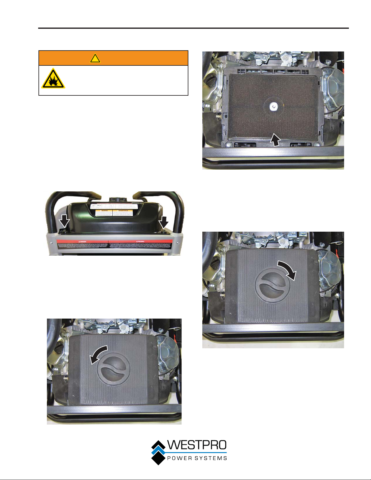
3. Remove the 4 mounting screws from the top of the
fuel tank (see Figure 42).
5. Remove the air cleaner element (see Figure 44).
Figure 44 – Air Cleaner Element
(Part No. 160059)
6. Insert the air cleaner element for dirt, dust and
debris. Do not wash the element. If the air cleaner
element is dirty, replace the filter.
7. Install the air cleaner element and install the cover
and knob (see Figure 45).
Figure 42 – Fuel Tank Screws
OTE:N The fuel tank is removed for photo
purposes. The air cleaner can be serviced
without removing the fuel tank.
4. Lift up the fuel tank slightly and unscrew the air
cleaner co
Figure 43).
ver knob and remove the cover (see
Figure 43 – Air Cleaner Knob and Cover
Figure 45 – Air Cleaner Cover Installation
8. Install the 4 screws for the fuel tank.
39
Page 40
MAINTENANCE
Cleaning the Air Filter – 8KPRO
The air filter must be cleaned after every 50 hours of
use or 3 months (frequency should be increased if
generator is operated in a dusty environment).
1. Turn off the generator and let it cool for several
utes if running.
min
2. Move the generator to a flat, level surface.
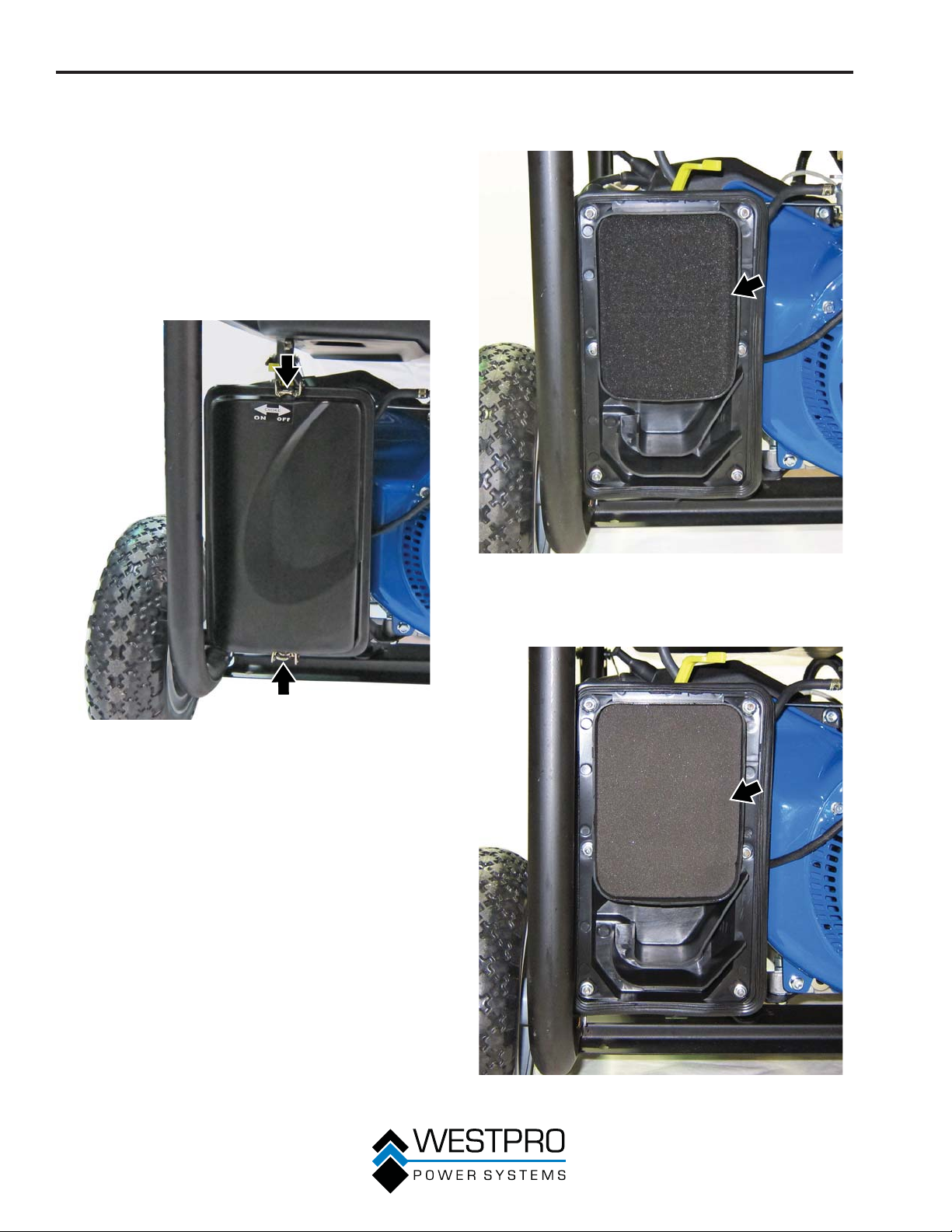
3. Unclip the clips on the top and bottom of the air
filter cover (see Figure 46) and remove the air filter
cover.
4. Remove the black coarse outside air filter (see
Figure 47).
Figure 46 – Removing Air Filter Cover
Figure 47 – Removing Coarse Outside Air Filter
5. Remove the gray fine inside air filter (see Figure
48).
40
Figure 48 – Removing Fine Inside Air Filter
Page 41
MAINTENANCE
6. Wash the foam air filter elements by submerging
the elements in a solution of household detergent
soap and warm water. Slowly squeeze the foam to
thoroughly clean.
NOTICE
NEVER twist or tear the foam air filter element
during cleaning or drying. Only apply slow but firm
squeezing action.
7. Rinse in clean water by submerging the air filter
elements in fresh water and applying a slow
squeezing action.
NOTICE
Never dispose of soap cleaning solution used to
clean the air filter by dumping the solution into
a sewer, on the ground, or into groundwater or
waterways. Always be environmentally responsible.
Follow the guidelines of the EPA or other
governmental agencies for proper disposal of
hazardous materials. Consult local authorities or
reclamation facility.
8. Dispose of used soap cleaning solution properly.
Dry the air filter elements by again applying a slow
9.
firm squeezing action.
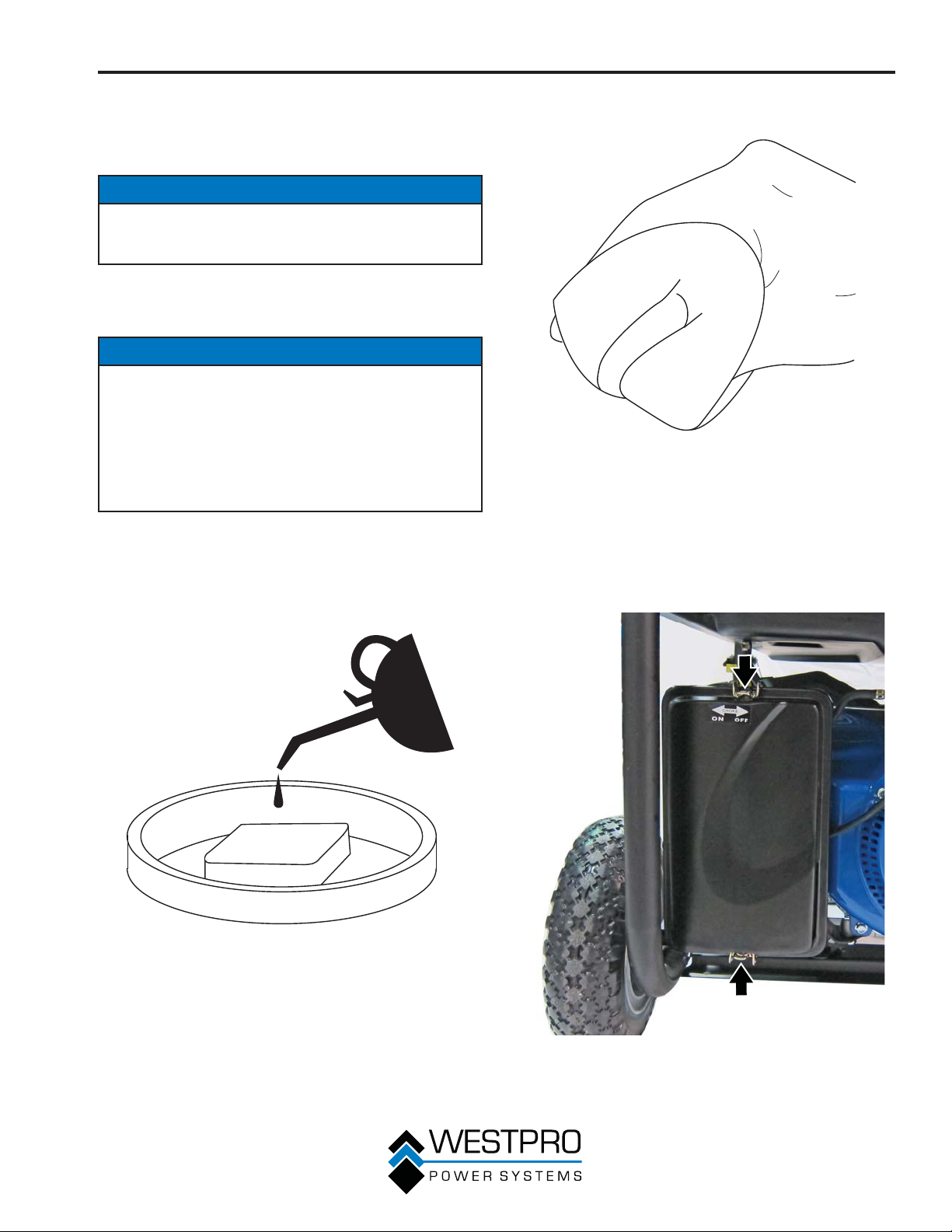
10. Once the air filters are dry, coat the air filters with
clean engine oil (see Figure 49).
11. Squeeze the filters to remove any excess oil (see
Figure 50).
Figure 50
12. Install the gray fine inside air filter into the air filter
housing first.
Install the black coarse outside air filter on top of
13.
the fine filter.
14. Install the air filter cover by clipping the clips on the
top and bottom of the air filter assembly (see Figure
51).
Figure 49
Figure 51 – Installation of Air Filter Cover
41
Page 42
MAINTENANCE
SPARK PLUG MAINTENANCE
The spark plug must be checked and cleaned after
every 100 hours of use or 6 months and must be
replaced after 300 hours of use or every year.
1. Stop the generator and let it cool for several
min
utes if running.
2. Move the generator to a flat, level surface.
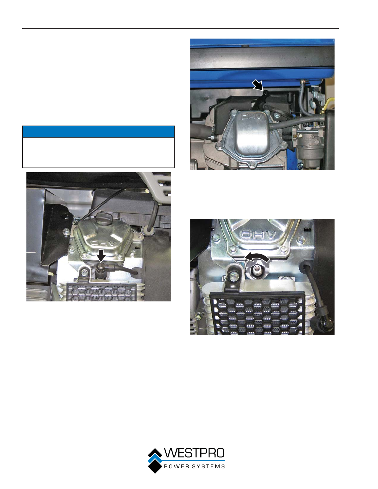
3. Remove the spark plug boot by firmly pulling the
plastic spark plug boot handle directly away from
the engine (see Figure 52 and Figure 53).
NOTICE
Never apply any side load or move the spark plug
laterally when removing the spark plug. Applying a
side load or moving the spark plug laterally may crack
and damage the spark plug boot.
Figure 53 – Removal of Spark Plug Boot – 8KPRO
4. Clean area around the spark plug.
5. Using the 13/16" spark plug socket wrench
provided, remove the spark plug from the cylinder
head (see Figure 54 and Figure 55).
Figure 52 – Removal of Spark Plug Boot – 10KPRO
42
Figure 54 – Removing Spark Plug – 10KPRO
Page 43
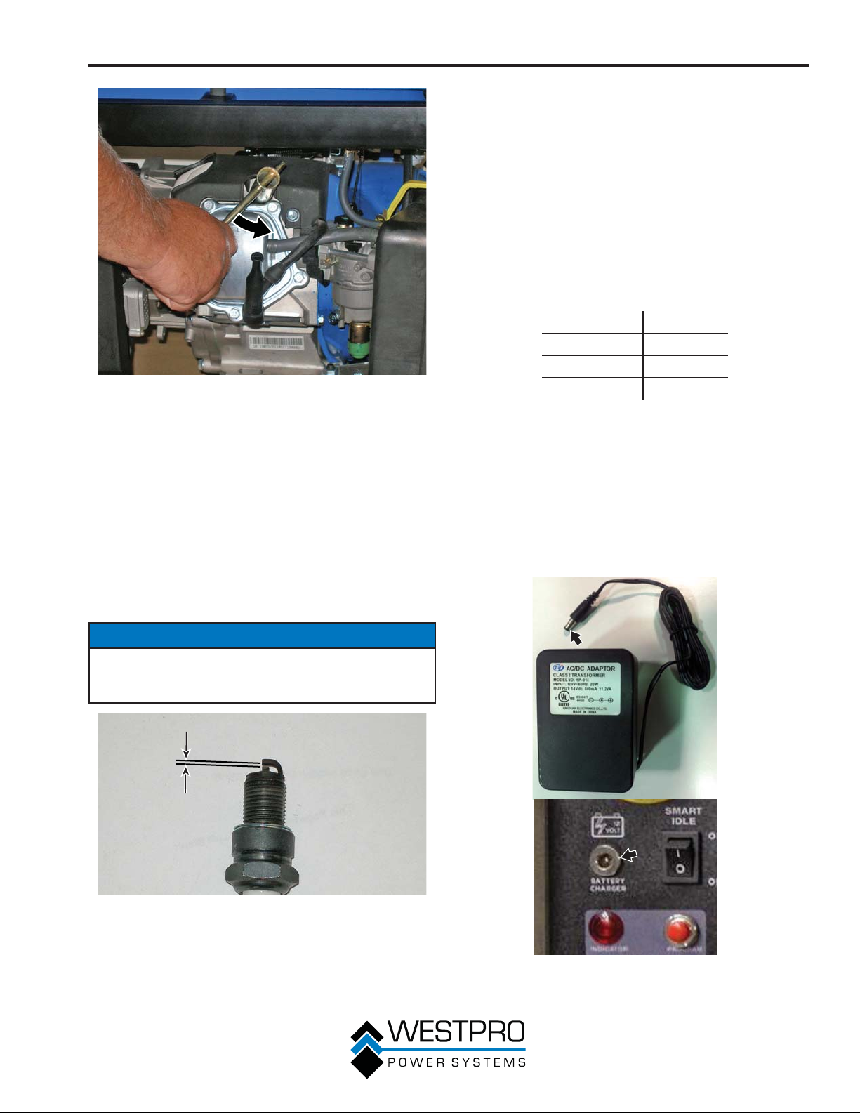
Figure 55 – Removing Spark Plug – 8KPRO
6. Place a clean rag over the opening created by the
val of the spark plug to make sure no dirt can
remo
get into the combustion chamber.
7. Inspect the spark plug for:
x Cracked or chipped insulator
x Excessive wear
x Spark plug gap (the acceptable limit of 0.024 –
0.032 in. [0.60 – 0.80 mm]) (see Figure 56).
If the spark plug fails any one of the conditions
listed above, replace the plug with a Champion
RN9YC plug or equivalent.
MAINTENANCE
8. Install the spark plug by carefully following the steps
outlined belo
a - Carefully insert the spark plug back into the
cylinder head. Hand-thread the spark plug until
it bottoms out.
b - Using the 13/16" spark plug socket wrench
pro
seated.
c - Replace the spark plug boot, making sure the
boot fully engages the spark plug’s tip.
Recommended Spark Plug Replacement:
BATTERY SERVICE
To ensure the battery remains charged, the generator
should be started every 2 to 3 months and run for
a minimum of 15 minutes or the charger should be
plugged into the generator and the generator should be
charged overnight. Plug the cord from the charger into
the charging port on the generator. Plug the charger into
a 110/120-volt AC outlet (see Figure 57).
w:
vided, turn the spark plug to ensure it is fully
AutoLite 63
Champion RN9YC
Bosch WR7DS
Torch F6RTC
NOTICE
Only use the recommended spark plug (Champion
RN9YC or equivalent). Using a non-recommended
spark plug could result in damage to the engine.
Figure 56 – Spark Plug Gap Requirements
Figure 57 – 120-Volt AC Charger
43
Page 44
MAINTENANCE
Battery Replacement
1. Remove the spark plug wire from spark plug.
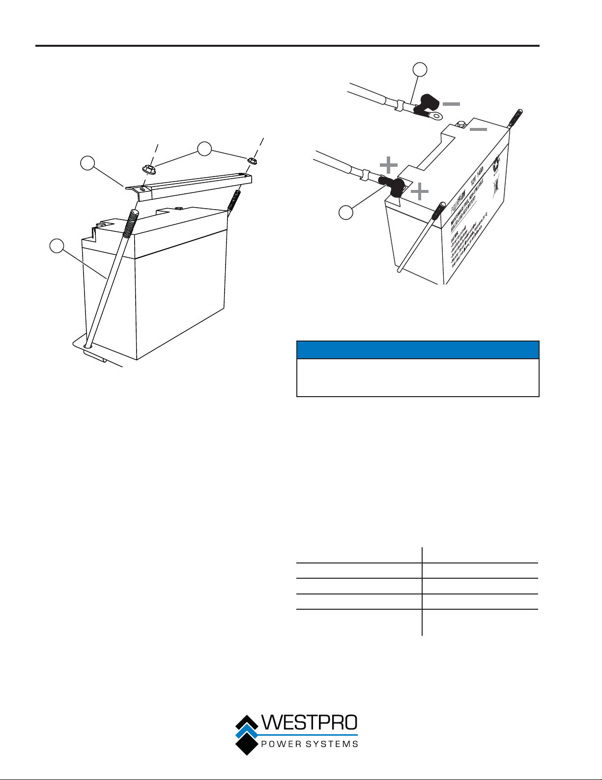
2. Loosen and remove the nuts on the battery holddown plate and remove the plate from the support
rods (see Figure 58).
1
2
3
Figure 58
1 - Nuts
2 - Battery Hold-
Down Plate
3. Tip the battery forward slightly to access battery
cables.
4. Disconnect the black negative (-) battery cable from
the battery first.
5. Disconnect the red positive (+) battery cable
second and remove the battery.
3 - Support Rods
2
1
Figure 59
1 - Red Positive (+)
Battery Cable
2 - Black Negative (-)
Battery Cable
NOTICE
Dispose of the used battery properly according to
the guidelines established by your local or state
government.
6. Install the new battery into the generator frame.
7. Connect the red positive (+) battery cable to the
battery first.
8. Connect the black negative (-) battery cable to the
battery second.
9. Install the battery hold-down plate using the nuts
removed in step 2.
10. Install the spark plug wire onto spark plug.
44
The battery for 10KPRO, Part No. 100170, is the same
as a wheelchair batter
Type Sealed lead-acid
Model LA-12V20-NB
Volts 12
Amp 21
Dimensions (L x H x W) 7.13 x 3 x 6.63 in.
y.
(18.1 x 7.6 x 16.8 cm)
Page 45
MAINTENANCE
The battery for 8KPRO, Part No. 100024, is the same
as a motorcycle/utility battery.
Type 14L-A2
Model CYLA214SXTA
Volts 12
Amp 14
Dimensions (L x H x W) 5.9 x 4.33 x 3.43 in.
(15.0 x 11.0 x 8.7 cm)
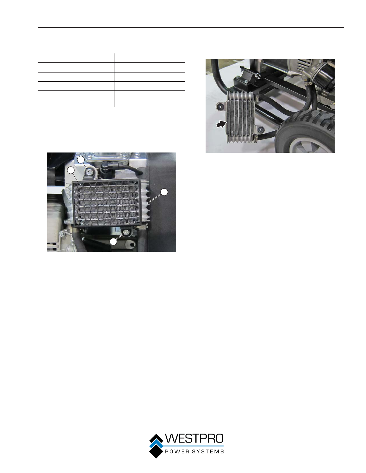
CLEANING THE ENGINE OIL
COOLER – 10KPRO
1. Remove the screws for the oil cooler (see Figure
60).
1
2
3
3. Inspect the oil fins for dirt and debris. Clean the fins
using compressed air not to exceed 30 psi (207
kPa) (see Figure 61).
Figure 61 – Oil Cooler Fins
4. Install the oil cooler and guard using the screws.
1
Figure 60 – Engine Oil Cooler
1 - Oil Cooler
Screws
2 - Oil Cooler Guard
2. Remove the oil cooler guard and the oil cooler.
3 - Oil Cooler
45
Page 46
MAINTENANCE
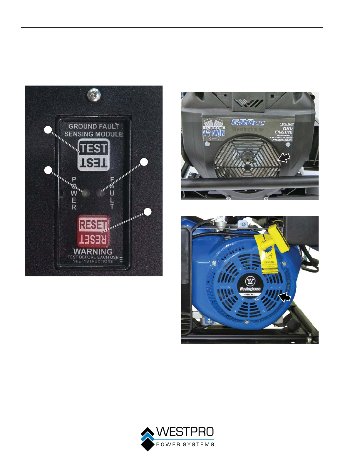
TESTING THE GROUND
FAULT SENSOR
1. Start the generator and allow it to warm up.
2. Press the test button on the ground fault sensor
(see Figure 62).
1
3
4
2
CLEANING THE GENERATOR
It is important to inspect and clean the generator before
every use.
Clean All Engine Air Inlet and Outlet Ports – Make
sure all engine air inlet and outlet ports are clean of any
dirt and debris to ensure the engine does not run hot
(see Figure 63 and Figure 64).
Figure 63 – Engine Air Inlet and Outlet Ports – 10KPRO
Figure 62 – Ground Fault Sensor Test
1 - Test Button
2 - Reset Button
3. The light next to “fault” will light and the main
er will trip.
break
4. If the main breaker does not trip, the ground
fault sensor is not working correctly and must be
repaired before the generator can be operated.
5. Press the reset button and reset the main breaker.
The light next to “fault” will go out and the light next
to “power” should light. Power will be restored to all
outlets.
46
3 - Fault Light
4 - Power Light
Figure 64 – Engine Air Inlet and Outlet Ports – 8KPRO
Page 47
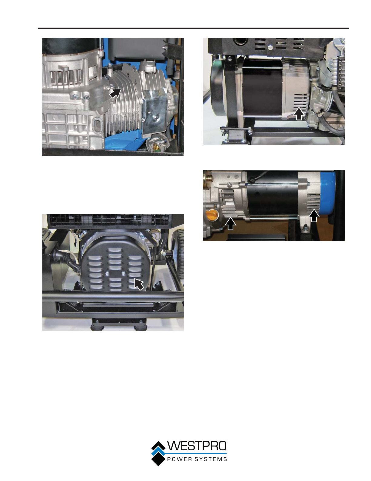
Figure 65 – Engine Cooling Fins – 8KPRO
Clean All Alternator Cooling Air Inlets and Exhaust
Ports – Make sure the cooling air inlets and exhaust
ports of the alternator are free of any debris and
obstructions. Use a vacuum cleaner to remove dirt and
debris stuck in the cooling air inlets and exhaust ports
(see Figure 66, Figure 67 and Figure 68).
MAINTENANCE
Figure 67 – Alternator Cooling Air Inlet and Outlet
Port – 10KPRO
Figure 66 – Alternator Cooling Air Inlet and Outlet Port
Figure 68 – Alternator Cooling Air Inlet and Outlet
Port – 8KPRO
General Cleaning of the Generator – Use a damp rag
to clean all remaining surfaces.
47
Page 48
MAINTENANCE
QUICK DRAIN
!
WARNING
Gasoline and gasoline vapors are
extremely flammable and explosive
under certain conditions. Wipe up any
spills immediately.
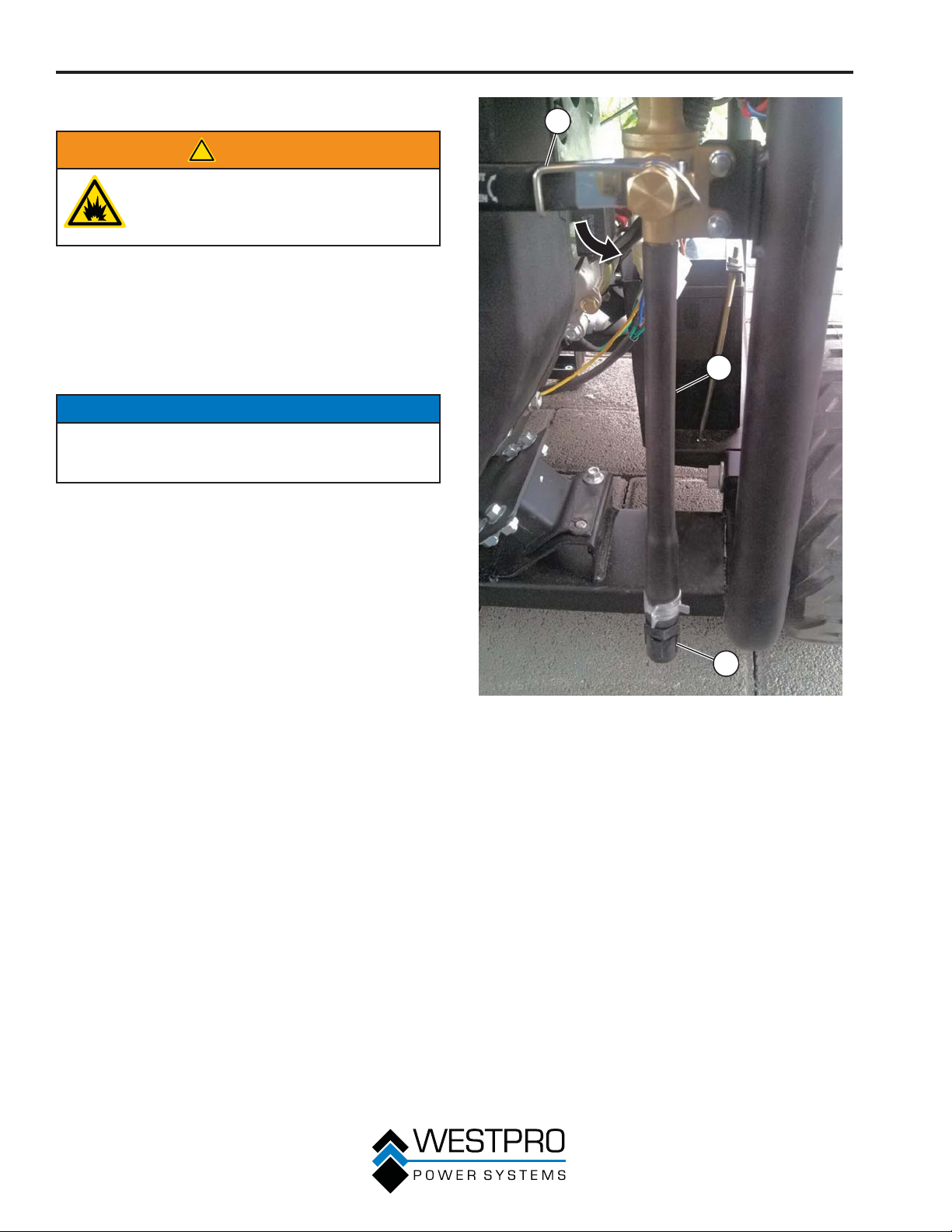
The generator is equipped with a quick-drain feature.
This feature will prevent the harmful effects of phaseseparated ethanol fuels. During the winter, the alcohol
and water can separate from the gasoline in blended
fuels. Because the water and alcohol are heavier than
gasoline, these corrosive fluids will sink to the bottom of
the fuel tank.
NOTICE
Never dispose of hazardous materials irresponsibly
by dumping them into a sewer, on the ground, into
groundwater or into waterways.
1. Remove the drain hose cap from the end of the
drain hose.
2. Open the quick drain valve (see Figure 69) and
drain the fuel into a suitable container.
1
2
3
Figure 69 – Quick Drain Valve
1 - Quick Drain Valve
2 - Drain Hose
3. Water and alcohol will appear clear or cloudy in the
fuel. Continue to drain until clean fuel is observed
coming out of the end of the drain hose.
4. Close the quick drain valve and install the drain
hose cap
5. Dispose of the collected fuel properly.
6. The quick drain procedure can also be used to
transfer fuel from the generator to be used in other
gasoline engine products.
.
3 - Drain Hose Cap
48
Page 49
STORAGE
!
WARNING
Never store a generator with fuel in the
tank indoors or in a poorly ventilated
area where the fumes can come in
contact with an ignition source such
as a: 1) pilot light of a stove, water
heater, clothes dryer or any other gas
appliance; or 2) spark from an electric
appliance.
NOTICE
Gasoline stored for as little as 60 days can go bad,
causing gum, varnish and corrosive buildup in fuel
lines, fuel passages and the engine. This corrosive
buildup restricts the flow of fuel, preventing an engine
from starting after a prolonged storage period.
Proper care should be taken to prepare the generator
for any storage.
MAINTENANCE
1. Clean the generator as outlined in Cleaning the
ator on page 46.
Gener
2. Drain all gasoline from the fuel tank as best as
possible.
3. With the fuel shutoff valve open, start the engine
and allow the generator to run until all the
remaining gasoline in the fuel lines and carburetor
is consumed and the engine shuts off.
4. Close the fuel shutoff valve.
5. Change the oil (see Changing Engine Oil –
10KPRO on page 37 and Changing Engine Oil
– 8KPRO on page 38).
6. Remove the spark plug (see Spark Plug Maintenance
on page 42) and place about 1 tablespoon of oil
in the spark plug opening. While placing a clean rag
over the spark plug opening, slowly pull the recoil
handle to allow the engine to turn over several times.
This will distribute the oil and protect the cylinder wall
from corroding during storage.
7. Replace the spark plug (see Spark Plug
Maintenance on page 42).
8. Move the generator to a clean, dry place for
storage.
49
Page 50
TROUBLESHOOTING
TROUBLESHOOTING
!
WARNING
Before attempting to service or
troubleshoot the generator, the owner
or service technician must first read
the owner’s manual and understand
and follow all safety instructions.
Failure to follow all instructions may
result in conditions that can lead to
voiding of the EPA certification or
product warranty, serious personal
injury, property damage or even death.
PROBLEM POTENTIAL CAUSE SOLUTION
1. Circuit breakers are tripped. 1. Reset the circuit breakers and check for overload
2.
The ground fault sensor is
tripped.
3. The power cord’s plug
connector is not fully engaged
Engine is running, but no
electrical output.
Engine will not start or
remain r
to start.
unning while trying
in the generator’s outlet.
4. Faulty or defective power cord 4. Replace power cord.
5. Faulty or defective electrical
appliance
6. If trying 1-5 above does not
solve the problem, the cause
might be the generator has a
fault.
1. Fuel shutoff valve is in the OFF
position.
2. Generator is out of gasoline. 2. Add gasoline to the generator (see page 28).
3. Fuel flow is obstructed. 3. Inspect and clean fuel delivery passages.
4. Starting battery may have
insufficient charge
5. Dirty air filter 5. Inspect and replace the air filter (see page 39).
6. Low oil level shutdown switch
is preventing the unit from
starting.
7. Spark plug boot is not fully
engaged with the spark plug tip.
8. Spark plug is faulty. 8. Remove and check the spark plug. Replace if faulty
9. Stale fuel 9. Drain fuel and replace with fresh fuel (see page
10. If trying 1-9 above does not
solve the problem, the cause
might be the generator has a
fault.
condition (see page 30).
2. Reset the ground fault sensor (see page 46).
3. Verify plug connector is firmly engaged in the
generator’s outlet. If using the 240V outlet, make sure
plug connector is rotated 1/4 turn in the clockwise
direction.
5. Try connecting a known good appliance to verify the
generator is producing electrical power.
6. Take the generator to your nearest authorized
service dealer.
1. Move the fuel shutoff valve to the ON position (see
page 31).
4. Check battery output and charge battery as
necessary.
6. Check oil level and add oil if necessary (see pages
35 and 36).
7. Firmly push down on the spark plug boot to ensure
the boot is fully engaged (see page 42).
(see page 42).
28).
10. Take the generator to your nearest authorized
service dealer.
50
Page 51

PROBLEM POTENTIAL CAUSE SOLUTION
Remote start system not
working.
Generator suddenly stops
running.
Engine runs erratic; does
not hold a steady RPM.
TROUBLESHOOTING
1. Low battery in remote start key
b
fo
2. Exceeding the range of remote
start key fob
3. Remote start key fob not
programmed to generator
1. Generator is out of fuel. 1. Check fuel level (see page 28). Add fuel if
2. The low oil shutdown switch
has stopped the engine.
3. Too much load 3. Restart the generator and reduce the load.
4. If trying 1-3 above does
not solve the problem, the
cause might be a fault in the
generator.
1. Dirty air filter 1. Replace the air filter (see page 39).
Applied loads may be cycling
2.
on and off
3. If trying 1-2 above does
not solve the problem, the
cause might be a fault in the
generator.
1. Replace batteries in key fob.
2. Move closer to generator. Must be no more than 109
yards (100 M) away.
3. Program key fob to generator (see Programming the
Generator for Remote Start on page 29).
necessary.
2. Check oil level and add oil if necessary (see pages
35 and 36).
4. Take the generator to your nearest authorized
service dealer.
2. As applied loads cycle, changes in engine speed
may occur; this is a normal condition.
3. Take the generator to your nearest authorized
service dealer.
51
Page 52

Page 53

MANUAL DEL PROPIETARIO
Page 54

California
Proposition 65 Warning
The engine exhaust from this product
contains chemicals known to the state of
California to cause cancer, birth defects
or other reproductive harm.
Proposition 65 Warning
Certain components in this product and its
related accessories contain chemicals
known to the state of California to cause
cancer, birth defects or other reproductive
harm. Wash hands after handling.
California
EXCLUSIONES:
Toda la información, las ilustraciones y especificaciones de este manual se basan en la información más reciente disponible
al momento de la publicación. Las ilustraciones que se utilizan en este manual están destinadas a representar vistas de
referencia únicamente. Además, debido a nuestra política de mejora continua del producto podemos modificar la información,
las ilustraciones y/o las especificaciones para explicar y/o ejemplificar una mejora de producto, servicio o mantenimiento. Nos
reservamos el derecho a realizar cualquier cambio en cualquier momento sin aviso. Algunas imágenes pueden variar en función
del modelo que se presente.
TODOS LOS DERECHOS RESERVADOS:
Ninguna parte de esta publicación se puede reproducir ni usar por ningún medio, sea gráfico, electrónico o mecánico, incluido
el uso de fotocopias, grabaciones, grabaciones en cinta o de sistemas de almacenamiento y recuperación de información, sin el
permiso por escrito de Westpro Power Systems, LLC.
2
Page 55
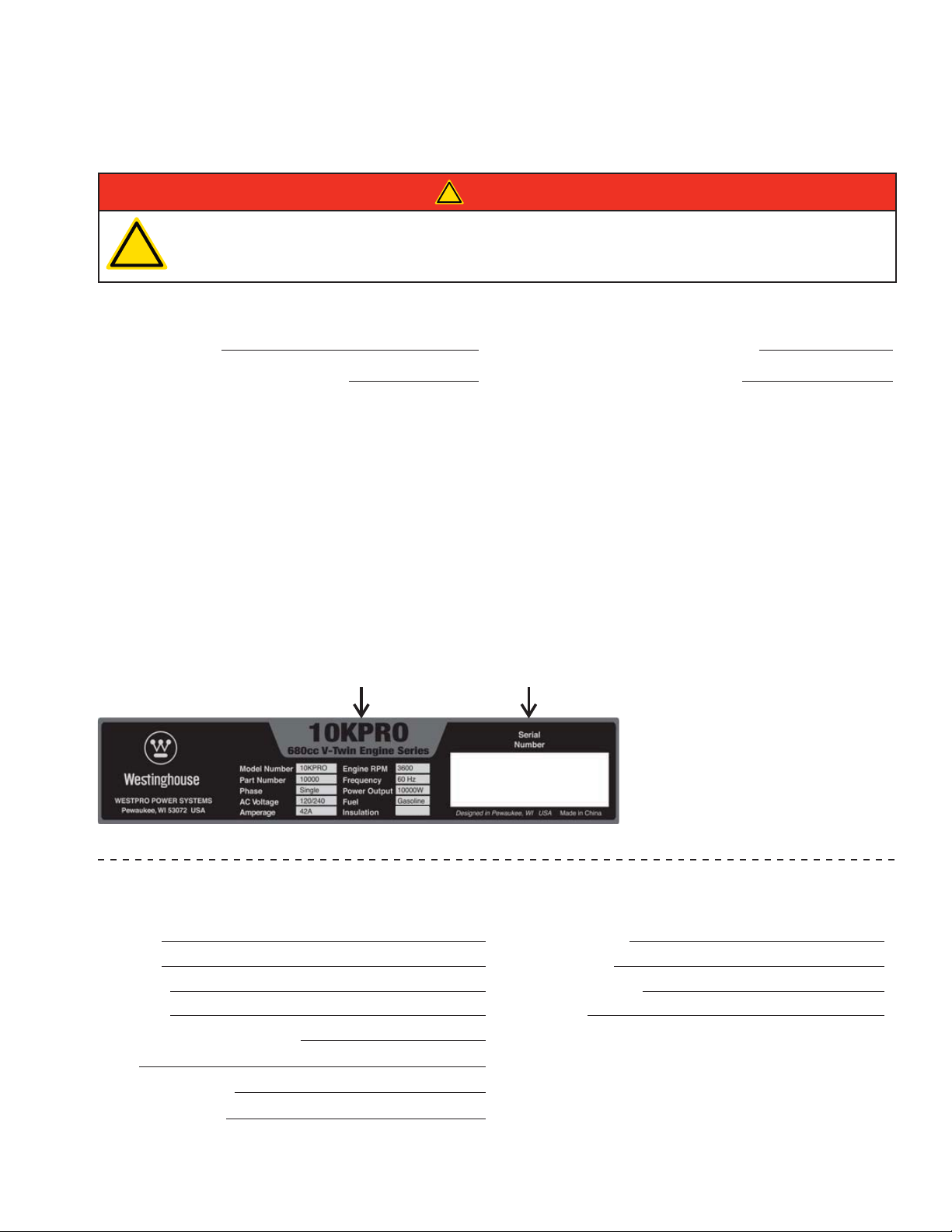
FELICITACIONES POR ADQUIRIR UN GENERADOR
WESTINGHOUSE
!
PELIGRO
Este manual contiene instrucciones importantes para la operación de este generador. Para su seguridad
y la de los demás, debe leer este manual completamente antes de operar el generador. Si no sigue
!
Para sus registros:
Fecha de compra: Número de modelo de la hidrolavadora:
Comprada a la Tienda/el Distribuidor: Número de serie de la hidrolavadora:
Recibo de compra: (conserve el recibo de compra para asegurar la cobertura sin problemas de la garantía)
Registro del producto
Para asegurar la cobertura sin problemas de la garantía es importante que registre el generador Westinghouse. Puede registralo
haciendo lo siguiente:
1. Complete el formulario de registro del producto que está a continuación y envíelo a:
2. Registración de su producto en línea en www.westpropower.com
Para registrar el generador deberá ubicar la siguiente información:
adecuadamente todas las instrucciones y precauciones, usted y otras personas pueden resultar
gravemente heridos o morir.
Registro del producto
Westpro Power Systems, LLC
W237 N2889 Woodgate Road, Unit B
Pewaukee, WI 53072
Número de Modelo Número de Serie
Class F
Formulario de registro del producto
INFORMACIÓN PERSONAL INFORMACIÓN SOBRE EL GENERADOR
Nombre: Número de modelo:
Apellido: Número de serie:
Dirección: Fecha de adquisición:
Dirección: Comprado a:
Ciudad, Estado, Código postal:
País:
Número de teléfono:
Correo electrónico:
Page 56

Page 57

ÍNDICE
FELICITACIONES POR ADQUIRIR UN GENERADOR WESTINGHOUSE .......................................................3
Para sus registros .........................................................................................................................................3
Registro del producto ...................................................................................................................................3
Formulario de registro del producto ..............................................................................................................3
SEGURIDAD .............................................................................................................................................................7
DEFINICIONES DE SEGURIDAD ......................................................................................................................7
DEFINICIONES DE LOS SÍMBOLOS DE SEGURIDAD ....................................................................................7
NORMAS GENERALES DE SEGURIDAD .........................................................................................................8
ETIQUETAS Y CALCOMANÍAS DE SEGURIDAD – 10KPRO..........................................................................10
ETIQUETAS Y CALCOMANÍAS DE SEGURIDAD – 8KPRO............................................................................12
DESEMBALAR .......................................................................................................................................................14
PROCEDIMIENTO PARA DESEMBALAR EL GENERADOR ..........................................................................14
ACCESORIOS DEL KIT DE RUEDAS ..............................................................................................................14
Componentes ............................................................................................................................................14
MONTAJE ...............................................................................................................................................................15
MONTAJE .........................................................................................................................................................15
INSTALACIÓN DE LA BATERÍA .......................................................................................................................16
CARACTERÍSTICAS ..............................................................................................................................................18
CARACTERÍSTICAS GENERALES DEL GENERADOR – 10KPRO ...............................................................18
CARACTERÍSTICAS DEL TABLERO DE CONTROL – 10KPRO .....................................................................20
CARACTERÍSTICAS GENERALES DEL GENERADOR – 8KPRO .................................................................21
CARACTERÍSTICAS DEL TABLERO DE CONTROL – 8KPRO .......................................................................23
FUNCIONAMIENTO ................................................................................................................................................24
ANTES DE ENCENDER EL GENERADOR .....................................................................................................24
CABLE DE SUMINISTRO .................................................................................................................................25
Usar cables prolongadores .........................................................................................................................25
Cable interruptor de transferencia ..............................................................................................................26
CONEXIONES DEL INTERRUPTOR DE TRANSFERENCIA ..........................................................................26
SOPORTE DE ELEVACIÓN ............................................................................................................................27
ANCLAJE DEL GENERADOR ..........................................................................................................................27
PROCEDIMIENTO PARA AGREGAR/CONTROLAR EL COMBUSTIBLE Y LOS LÍQUIDOS DEL MOTOR ..28
Procedimiento para controlar y/o agregar el aceite para motor..................................................................28
Procedimiento para agregar gasolina al depósito de combustible .............................................................28
PROGRAMACIÓN DEL GENERADOR PARA ARRANQUE REMOTO ............................................................29
ENCENDIDO DEL GENERADOR ....................................................................................................................29
DETENCIÓN DEL GENERADOR .....................................................................................................................32
Funcionamiento normal ..............................................................................................................................32
Durante una emergencia ............................................................................................................................32
PUESTA EN MARCHA DEL GENERADOR CON EL ARRANQUE REMOTO .................................................32
DETENCIÓN DEL GENERADOR CON EL ARRANQUE REMOTO ................................................................33
MANTENIMIENTO ..................................................................................................................................................34
MANTENIMIENTO ...........................................................................................................................................34
Cronograma de mantenimiento .................................................................................................................34
MANTENIMIENTO DEL ACEITE DEL MOTOR ................................................................................................35
Especificación del aceite del motor ............................................................................................................35
Procedimiento para controlar el aceite del motor – 10KPRO .....................................................................35
Procedimiento para controlar el aceite del motor – 8KPRO .......................................................................36
Procedimiento para agregar el aceite del motor – 10KPRO .......................................................................36
Procedimiento para agregar el aceite del motor – 8KPRO .........................................................................37
Procedimiento para cambiar el aceite del motor – 10KPRO ......................................................................37
Procedimiento para cambiar el aceite del motor – 8KPRO ........................................................................38
MANTENIMIENTO DEL FILTRO DE AIRE .......................................................................................................39
Inspeccione y reemplace el filtro de aire – 10KPRO ..................................................................................39
Limpieza del filtro de aire – 8KPRO ...........................................................................................................40
MANTENIMIENTO DE LA BUJÍA DE ENCENDIDO .........................................................................................42
MANTENIMIENTO DE LA BATERÍA .................................................................................................................43
Reemplazo de la batería ............................................................................................................................44
5
Page 58

ÍNDICE
LIMPIEZA DEL ENFRIADOR DE ACEITE DEL MOTOR – 10KPRO ...............................................................45
PROBAR EL SENSOR DE FALLA A TIERRA ..................................................................................................46
LIMPIEZA DEL GENERADOR .........................................................................................................................46
DRENAJE RÁPIDO ..........................................................................................................................................48
ALMACENAMIENTO .........................................................................................................................................49
SOLUCIÓN DE PROBLEMAS ................................................................................................................................50
SOLUCIÓN DE PROBLEMAS .........................................................................................................................50
6
Page 59
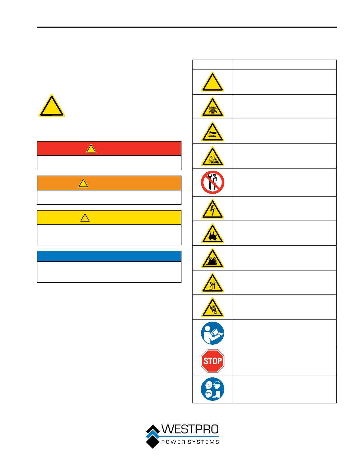
SEGURIDAD
DEFINICIONES DE
SEGURIDAD
Las palabras PELIGRO, ADVERTENCIA, PRECAUCIÓN y
AVISO se usan a lo largo de este manual para destacar la
información importante. Asegúrese de que todo aquel que
trabaje con el equipo o cerca de él conozca el significado de
estas alertas.
Este símbolo de alerta de seguridad
aparece con la mayoría de las
!
Indica una situación de riesgo que, si no se evita,
causará lesiones graves o la muerte.
Indica una situación de riesgo que, si no se evita,
podría causar lesiones graves o la muerte.
declaraciones de seguridad. Significa:
¡atención, esté alerta, su seguridad está
en riesgo! Lea y respete el mensaje que
aparece a continuación del símbolo de
alerta de seguridad.
!
PELIGRO
!
ADVERTENCIA
DEFINICIONES DE LOS
SÍMBOLOS DE SEGURIDAD
Símbolo Descripción
Símbolo de alerta de seguridad
!
Peligro de asfixia
Peligro de quemaduras
Peligro de explosión/presión
No deje las herramientas en la zona
Peligro de electrocución
!
PRECAUCIÓN
Indica una situación de riesgo que, si no se evita,
podría causar lesiones menores o de gravedad
moderada.
AVISO
Indica una situación que puede dañar el generador, la
propiedad personal y/o el entorno, o que puede hacer que
el equipo funcione incorrectamente.
OTA:N Indica un procedimiento, una práctica o una
condición que debe seguirse a fin de que el
generador funcione conforme al diseño.
Peligro de explosión
Peligro de incendio
Peligro de elevación
Peligro de aplastamiento
Lea las instrucciones del fabricante
Lea los mensajes de seguridad antes de
proceder
Use Equipo de Protección Personal
(PPE, por sus siglas en inglés)
7
Page 60
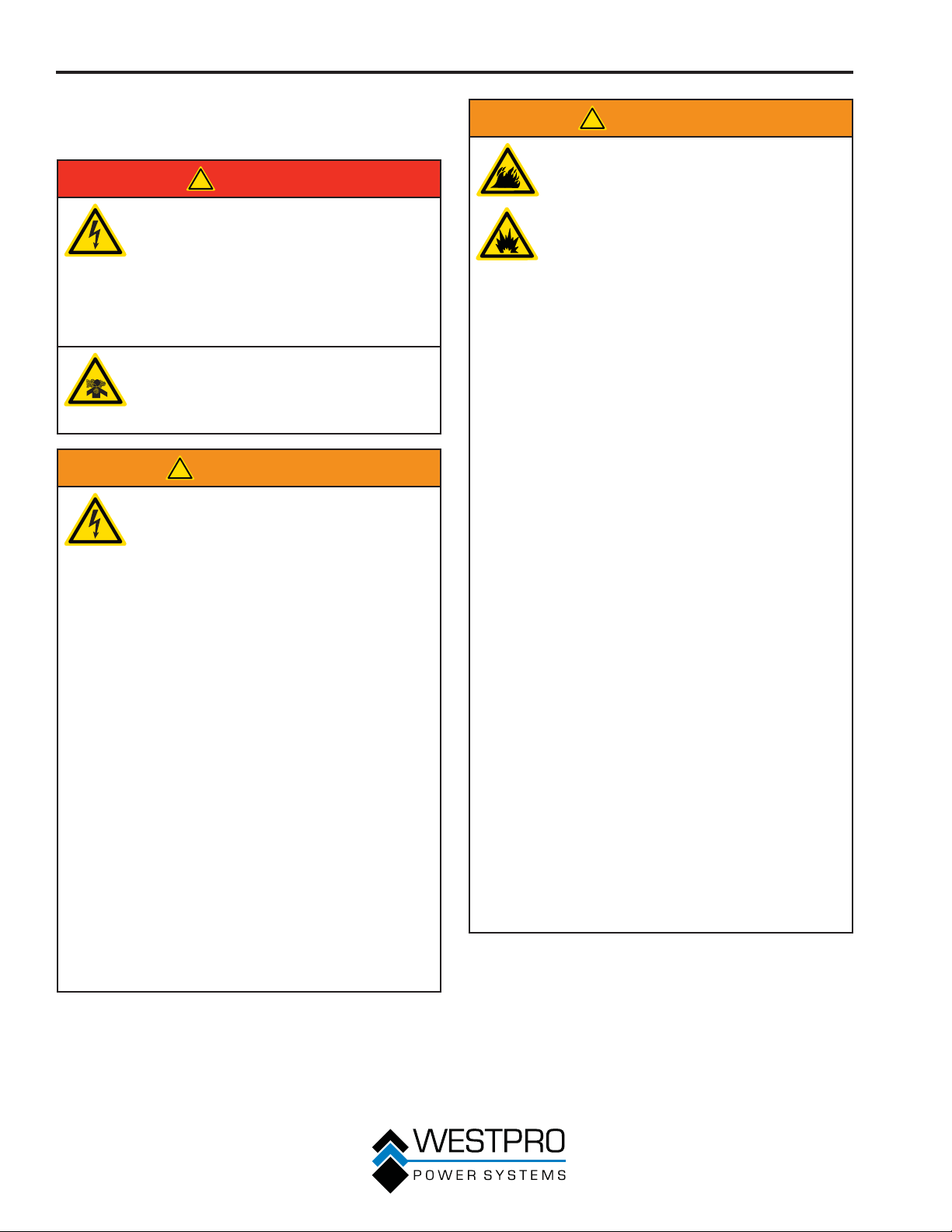
SEGURIDAD
NORMAS GENERALES DE
SEGURIDAD
!
PELIGRO
Nunca use el generador en lugares
mojados o húmedos. Nunca exponga el
generador a lluvia, nieve, rociado de agua
o agua estancada durante el uso. Proteja
el generador de todas las condiciones
climáticas peligrosas. La humedad o el
hielo pueden causar un cortocircuito u otro
tipo de problema de funcionamiento en el
circuito eléctrico.
Nunca opere el generador en un lugar
cerrado. El escape del motor contiene
monóxido de carbono. Sólo debe operar
el generador en exteriores y alejado de
ventanas, puertas y ventilaciones.
!
ADVERTENCIA
El voltaje del generador puede producir
lesiones graves o la muerte.
• Nunca utilice el generador bajo la
lluvia o en planicies de inundación a
menos que se tomen las precauciones
correspondientes para evitar que quede
expuesto a la lluvia o la inundación.
• No utilice nunca prolongadores
desgastados o dañados.
• Siempre debe contratar a un electricista
matriculado para que conecte el
generador al circuito de la red general.
• Nunca toque el generador cuando está en
marcha si el generador está húmedo o si
usted tiene las manos mojadas.
• Nunca utilice el generador en zonas con
alto nivel de conducción como cerca de
plataformas metálicas o estructuras de
acero.
• Utilice siempre prolongadores
conectados a tierra. Siempre use
herramientas mecánicas de tres hilos o
con aislamiento doble.
• Nunca toque los terminales que tienen
corriente o los hilos desnudos mientras
el generador está en funcionamiento.
• Asegúrese de que el generador esté
conectado a tierra correctamente antes
de utilizarlo.
!
ADVERTENCIA
La gasolina y los vapores de la gasolina
son extremadamente inflamables y
explosivos en determinadas condiciones.
• Siempre debe hacer la recarga de
combustible del generador en exteriores,
en una zona bien ventilada.
• Nunca saque el tapón de combustible
con el motor en marcha.
• Nunca haga la recarga de combustible
del generador mientras el motor está
en marcha. Apague siempre el motor y
deje que se enfríe el generador antes de
recargar combustible.
• Siempre cargue el depósito de
combustible con gasolina.
• Cuando realice la recarga, mantenga
alejadas las chispas, llamas abiertas u
otras formas de ignición (como cerillos,
cigarrillos, fuentes de electricidad
estática).
• Nunca sobrecargue el depósito de
combustible. Deje espacio para
la expansión del combustible. La
sobrecarga del depósito de combustible
puede producir un desbordamiento
repentino de gasolina y hacer que la
gasolina derramada tome contacto con
superficies CALIENTES. El combustible
derramado puede encenderse. Si se
derrama combustible sobre el generador,
debe eliminar los derrames de inmediato.
Deseche los trapos como corresponda.
Deje que se seque la superficie donde
se produjo el derrame antes de operar el
generador.
• Utilice protección ocular durante la
recarga de combustible.
• Nunca utilice gasolina como agente de
limpieza.
• Almacene los recipientes que contienen
gasolina en una zona bien ventilada,
alejada de los combustibles o las fuentes
de encendido.
• Controle si hay pérdidas de combustible
después de la recarga de combustible.
Nunca opere el motor si se descubre que
hay una fuga de combustible.
8
Page 61
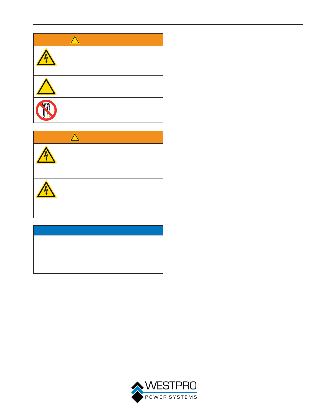
!
!
ADVERTENCIA
Nunca opere el generador si se
sobrecalientan los componentes eléctricos,
si cae la salida de energía eléctrica, si salen
chispas, llamas o humo del generador, o si
los receptáculos están dañados.
Nunca use el generador para alimentar
equipos de asistencia médica.
Siempre retire del generador las
herramientas u otros equipos de servicio
que se utilicen durante el mantenimiento
antes de usarlo.
!
ADVERTENCIA
Siempre debe actuar con precaución en
proximidad del generador. El generador
está equipado con una función de arranque
remoto que se podría activar, lo que
permite arrancar el generador sin previa
advertencia.
Siempre debe desconectar el cable
negativo (-) de la batería para realizar
tareas de reparación o mantenimiento en el
generador. De esta manera se desactivará
el sistema de arranque remoto, con lo
que se evita el arranque accidental del
generador.
SEGURIDAD
AVISO
Nunca modifique el generador.
Nunca utilice el generador si vibra a altos niveles, si la
velocidad del motor cambia significativamente o si el motor
falla con frecuencia al encender.
Siempre desconecte las herramientas y los artefactos del
generador antes del encendido.
9
Page 62
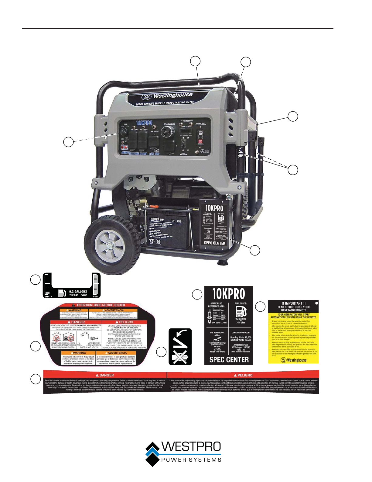
SEGURIDAD
ETIQUETAS Y CALCOMANÍAS DE SEGURIDAD – 10KPRO
1
6
2
3
4
5
1
5
6
2
3
4
Figura 1
10
Page 63
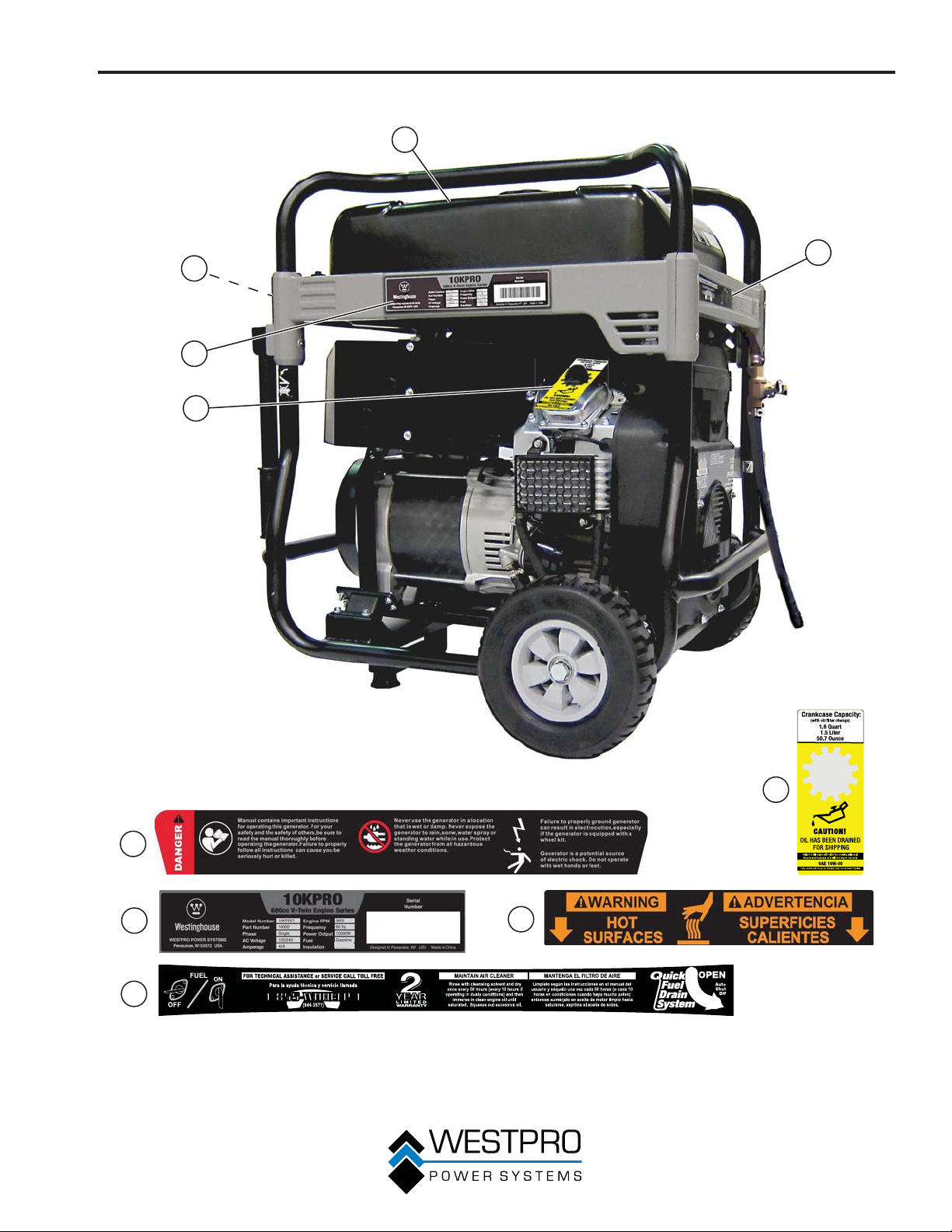
SEGURIDAD
1
3
4
2
5
5
1
2
Class F
4
3
Figura 2
11
Page 64
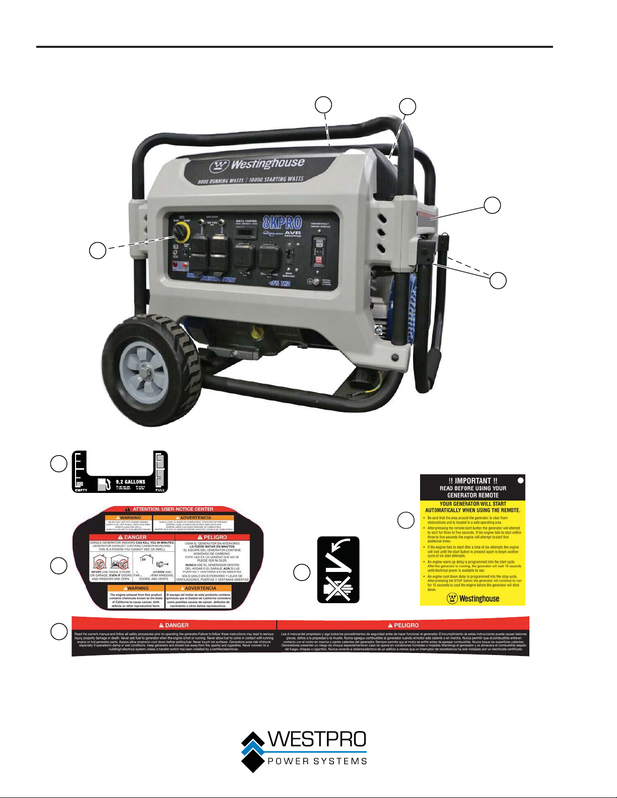
SEGURIDAD
ETIQUETAS Y CALCOMANÍAS DE SEGURIDAD – 8KPRO
1
5
2
3
4
1
5
2
3
4
Figura 3
12
Page 65
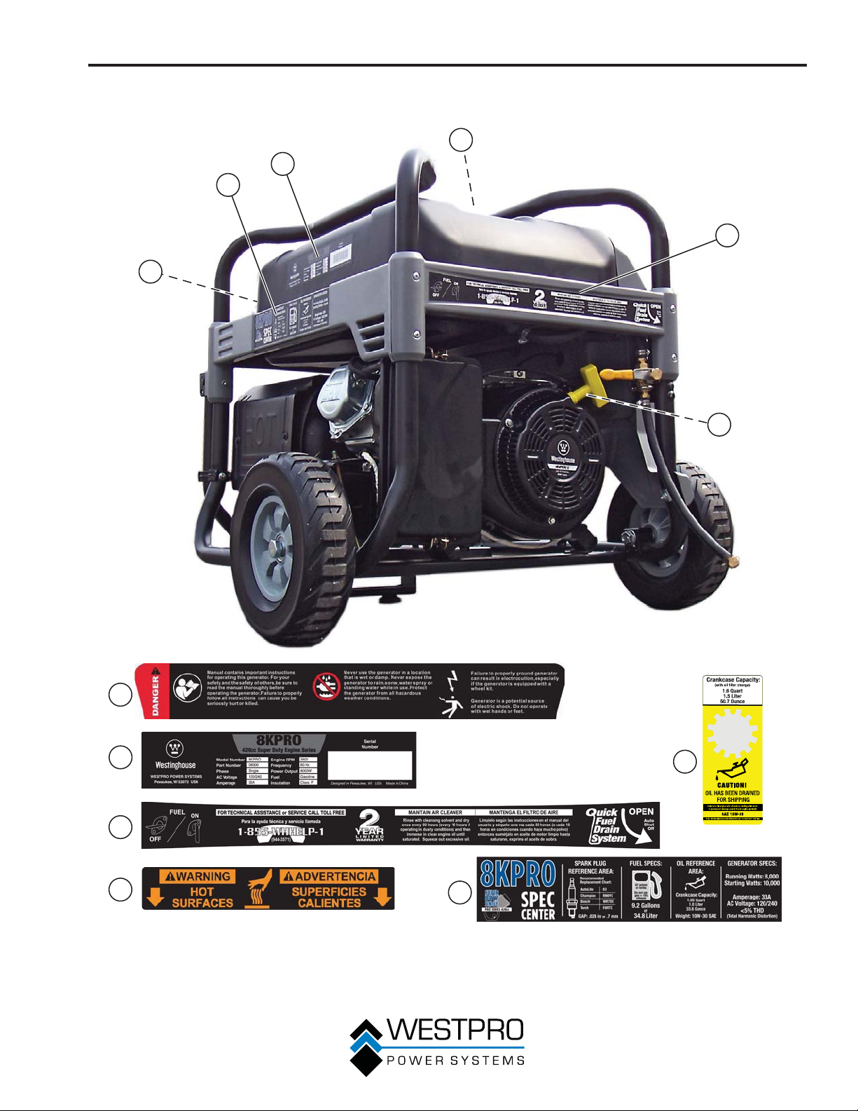
SEGURIDAD
1
2
6
3
4
5
1
2
3
4
13
6
Figura 4
5
Page 66
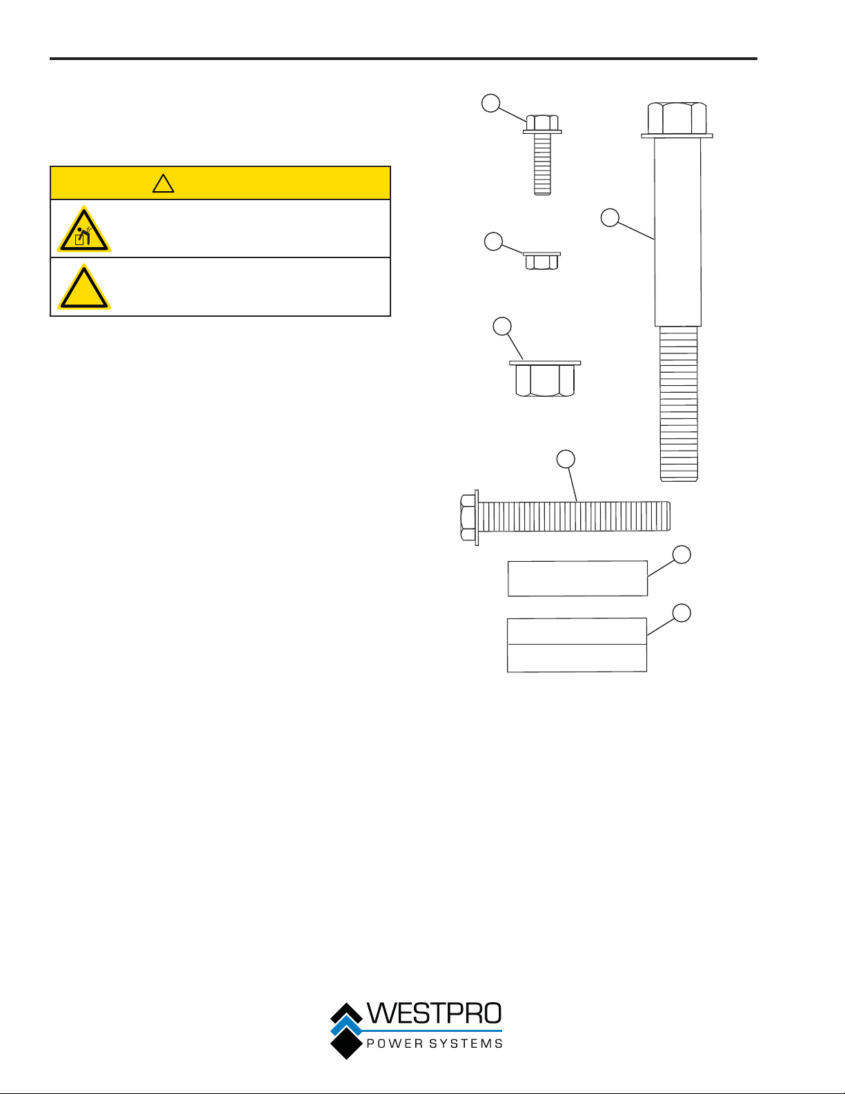
PROCEDIMIENTO PARA DESEMBALAR LA UNIDAD
PROCEDIMIENTO
PARA DESEMBALAR EL
GENERADOR
!
PRECAUCIÓN
Siempre debe solicitar ayuda para levantar
el generador. El generador es pesado,
levantarlo puede causarle lesiones físicas.
Evite cortar sobre o cerca de grapas para
evitar lesiones personales.
!
Herramientas requeridas: trincheta o dispositivo similar.
1. Corte con cuidado la cinta de embalar que está en la
parte superior de la caja.
2. Pliegue las aletas superiores para dejar a la vista el
manual.
3. Extraiga los accesorios del kit de las ruedas.
4. Corte con cuidado dos costados de la caja para extraer
el generador.
ACCESORIOS DEL KIT DE
1
4
2
3
5
RUEDAS
Si falta alguna pieza, ubique a un distribuidor autorizado de
Westinghouse Generator en www.westpropower.com o llame
al 1-855-WHHELP1 (1-855-944-3571).
Componentes:
Ruedas (2)
Bolsa de herramientas (1)
Llave de cubo para bujías (1)
Cargador de la batería (1)
Soporte de elevación (1)
Botella de 0,75 L de aceite
SAE 10W30 – 10KPRO (2)
Botella de 1 L de aceite SAE
10W30 – 8KPRO (1)
Pata de montaje (1)
Embudo de aceite (1)
Llavero de arranque remoto (1)
Figura 5 – Hardware
1 - Perno de brida
M8 x 18 mm
(se usan 2)
2 - Contratuerca de
brida M8
(se usan 4)
3 - Tuerca de brida
dentada M12
(se usan 4)
6
7
4 - Perno del eje de la
rueda
M12 x 1,5 mm
(se usan 2)
5 - Pernos
hexagonales M8 x
50 mm
(se usan 2)
6 - Manguito
separador
(se usan 2)
7 - Manguito de goma
(se usan 2)
14
Page 67
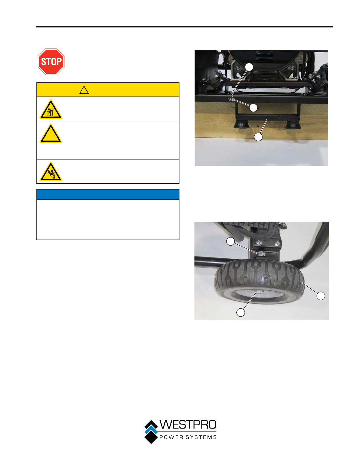
MONTAJE
MONTAJE
Antes de ensamblar el generador, analice
Seguridad en la página 7 y los
siguientes mensajes de seguridad.
!
PRECAUCIÓN
Nunca levante el generador sin ayuda. El
generador es pesado y levantarlo sin ayuda
podría causarle lesiones personales.
Nunca utilice las manijas como punto
de elevación para sostener todo el peso
!
Para ensamblar el generador se deberá elevar la unidad.
Asegúrese de que todo el aceite del motor y el combustible
se drenen de la unidad antes del ensamblado.
Una vez montado, el kit de las ruedas no está diseñado
para usarse en carreteras. El kit de las ruedas está
diseñado para usarse únicamente en este generador.
Herramientas requeridas: bolsa de herramientas (se
incluye).
del generador. Utilice las manijas sólo
para mover el generador levantando las
manijas y usando las ruedas para mover el
generador.
Sea precavido al plegar las manijas.
Podrían quedarle atrapados las manos y los
dedos y ser apretados.
AVISO
3. Instale la pata de montaje al bastidor con tuercas y
pernos de brida M8 (vea la Figura 6).
1
2
3
Figura 6 – Ensamble la pata de montaje al bastidor
1 - Perno de brida M8
2 - Tuerca de brida M8
4. Instale el perno de eje de 12 mm x 1,5 mm por el soporte
de eje sobre el bastidor.
5. Instale la tuerca de brida y apriete (vea la Figura 7).
3 - Pata de montaje
1
1. Coloque el generador sobre una superficie plana.
2. Con un bloque de madera, levante y sostenga la parte
trasera del generador.
3
Figura 7 – Ensamble las ruedas al bastidor
1 - Tuerca de brida
2 - Rueda
3 - Perno de eje
2
15
Page 68
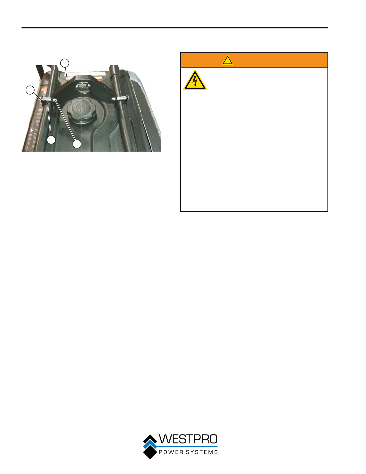
MONTAJE
6. Instale el soporte de elevación usando los pernos
hexagonales, separadores y contratuerca
8).
s (vea la Figura
1
2
3
Figura 8 – Instalación del soporte de elevación
1 - Soporte de
elevación
2 - Perno hexagonal
4
3 - Manguito separador
4 - Contratuerca
INSTALACIÓN DE LA BATERÍA
!
ADVERTENCIA
Para evitar descargas eléctricas:
• SIEMPRE conecte primero el cable
positivo (+) (capuchón rojo) de la batería
cuando conecte los cables de la batería.
• SIEMPRE desconecte primero el cable
negativo (-) (capuchón negro) de la
batería cuando desconecte los cables de
la batería.
• NUNCA conecte el cable negativo (-) de
la batería (capuchón negro) al terminal
positivo (+) de la batería.
• NUNCA conecte el cable positivo (+) de
la batería (capuchón rojo) al terminal
negativo (-) de la batería.
• NUNCA conecte ambos terminales de la
batería simultáneamente.
• NUNCA coloque una herramienta
metálica cruzando ambos terminales de
la batería.
• SIEMPRE use herramientas aisladas o no
conductoras cuando instale la batería.
OTA:N El generador viene equipado con el cable
1. Verifique que el cable positivo (+) de la batería (capuchón
2. Quite con cuidado la envoltura protectora que rodea la
3. Ubique el cable negativo (-) al cable del alternador, retire
positivo de la batería (capuchón rojo) ya
conectado.
rojo) esté bien ajustado al terminal positivo (+) de la
batería. Compruebe que el capuchón quede sobre el
terminal de la batería.
lengüeta del cable negativo (-) de la batería (capuchón
negro).
el lazo y dirija al terminal negativo (-) de la batería.
16
Page 69
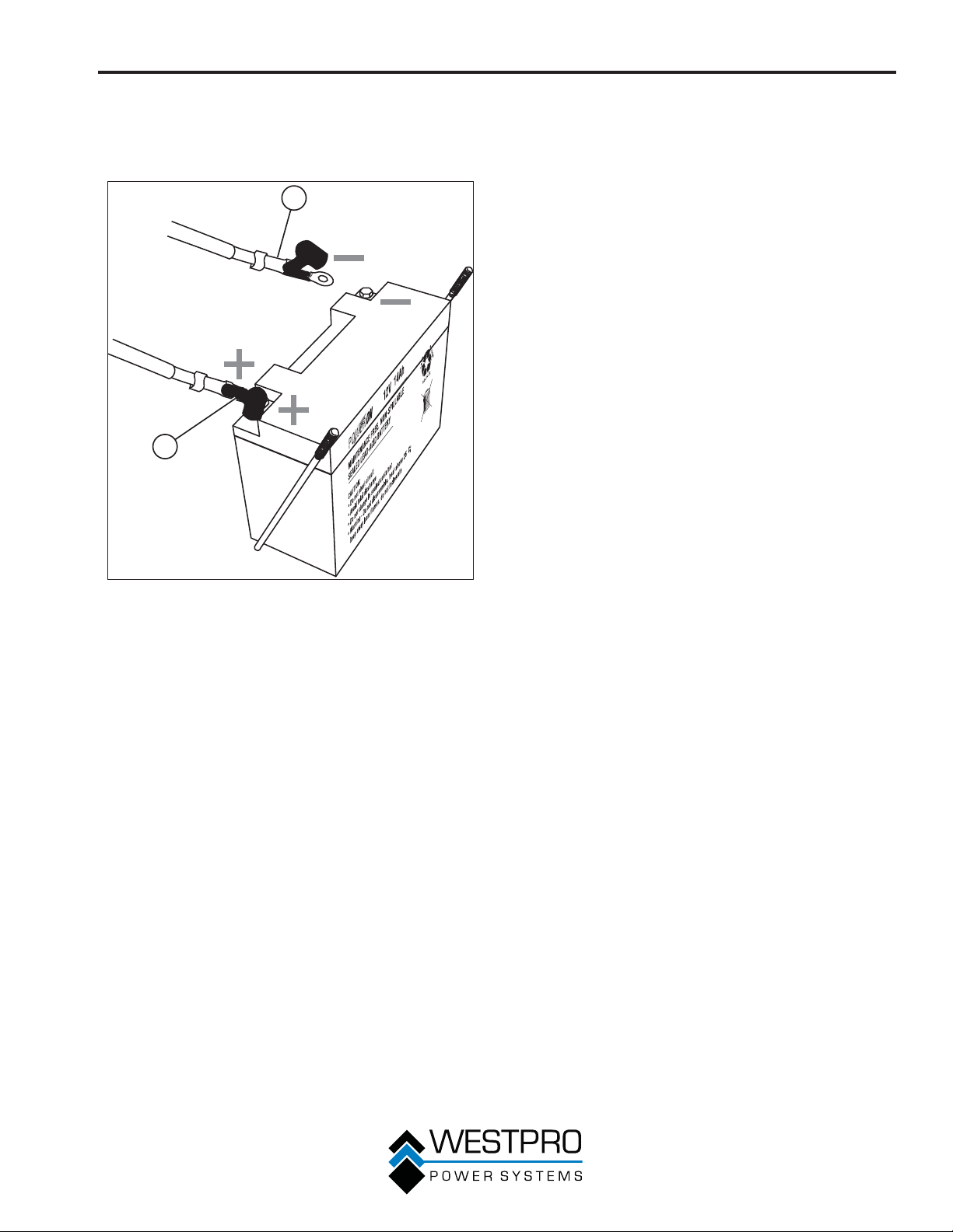
4. Tire hacia atrás el capuchón negro y sujete bien el cable
negativo (-) de la batería (capuchón negro) al terminal
negativo (-) de la batería como se indica en la Figura 9.
Reponga el capuchón negro para que proteja la lengüeta
del cable y el terminal de la batería.
2
1
MONTAJE
Figura 9 – Conexión del cable negativo (-) de la batería
1 - Cable (rojo)
positivo (+) de la
batería
(negro)
2 - Cable (negro)
negativo (-) de la
batería
17
Page 70
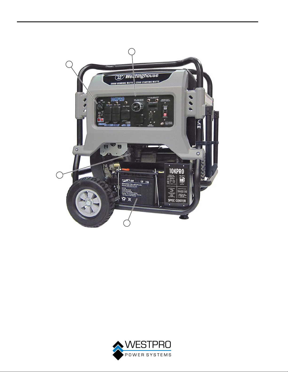
CARACTERÍSTICAS
CARACTERÍSTICAS GENERALES DEL GENERADOR – 10KPRO
2
1
4
Interruptor de control del motor: Enciende y
1 -
apaga el motor.
2 - Panel de control: Contiene los disyuntores y
los tomacorrientes.
3
Figura 10
3 - Batería: Se usa para arrancar el generador.
4 -
Varilla de medición de aceite: Retire la varilla
para comprobar el nivel de aceite del motor.
18
Page 71
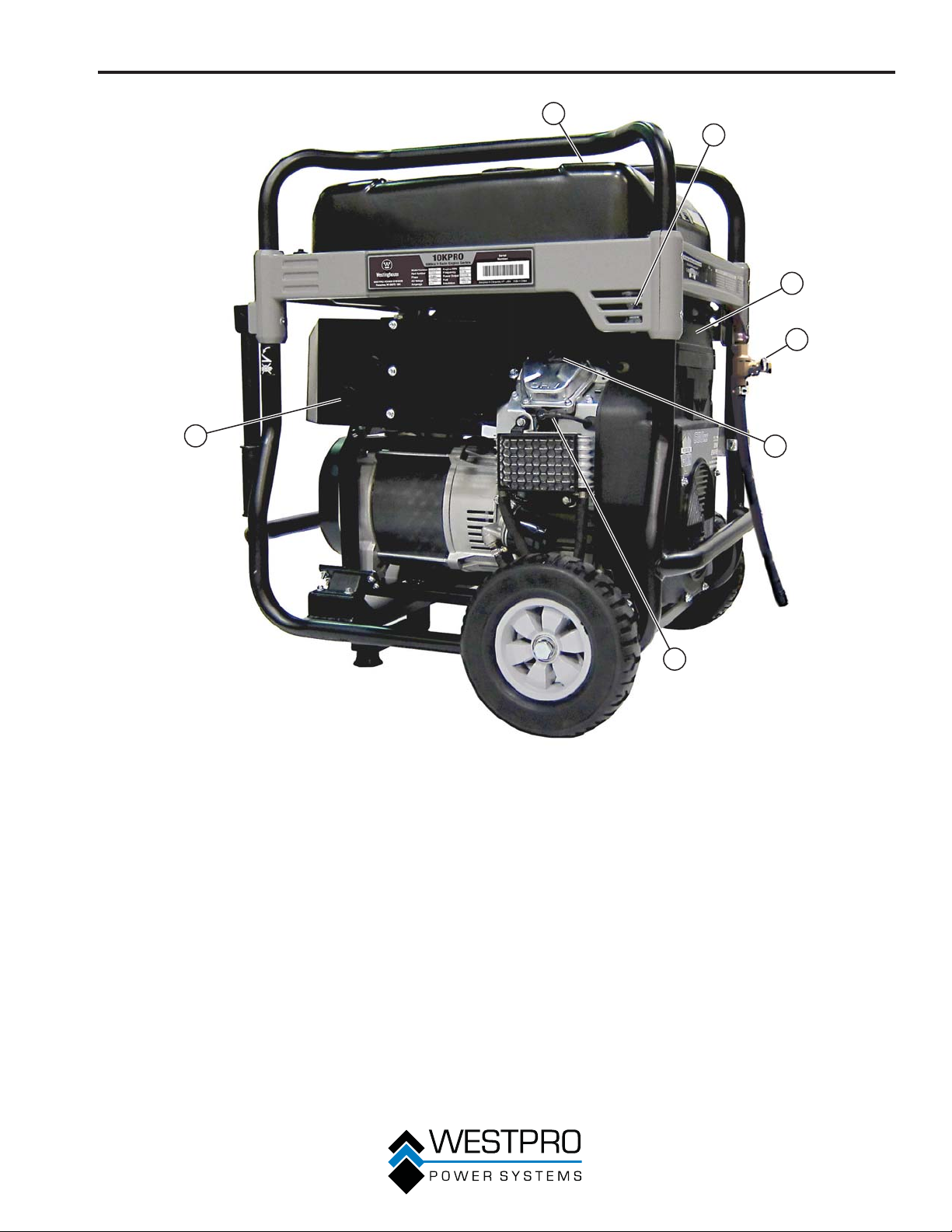
CARACTERÍSTICAS
1
2
3
4
7
1 -
Indicador de combustible: Indica el nivel de
combustible.
2 - Válvula de cierre de combustible: Controla el
flujo de combustible al motor.
3 - Cubierta del filtro de aire: Debe quitarse para
realizar el mantenimiento del filtro de aire.
4 - Válvula de drenaje rápido: Úsela para drenar
contaminantes del depósito de combustible.
5
6
Figura 11
5 - Tapón de llenado de aceite: Quítelo para
agregar aceite del motor.
6 - Capuchón (cable) de la bujía: Se debe quitar
cuando se realiza el mantenimiento del motor o
de la bujía.
7 - Silenciador: Evite el contacto hasta que el
motor se enfríe.
19
Page 72
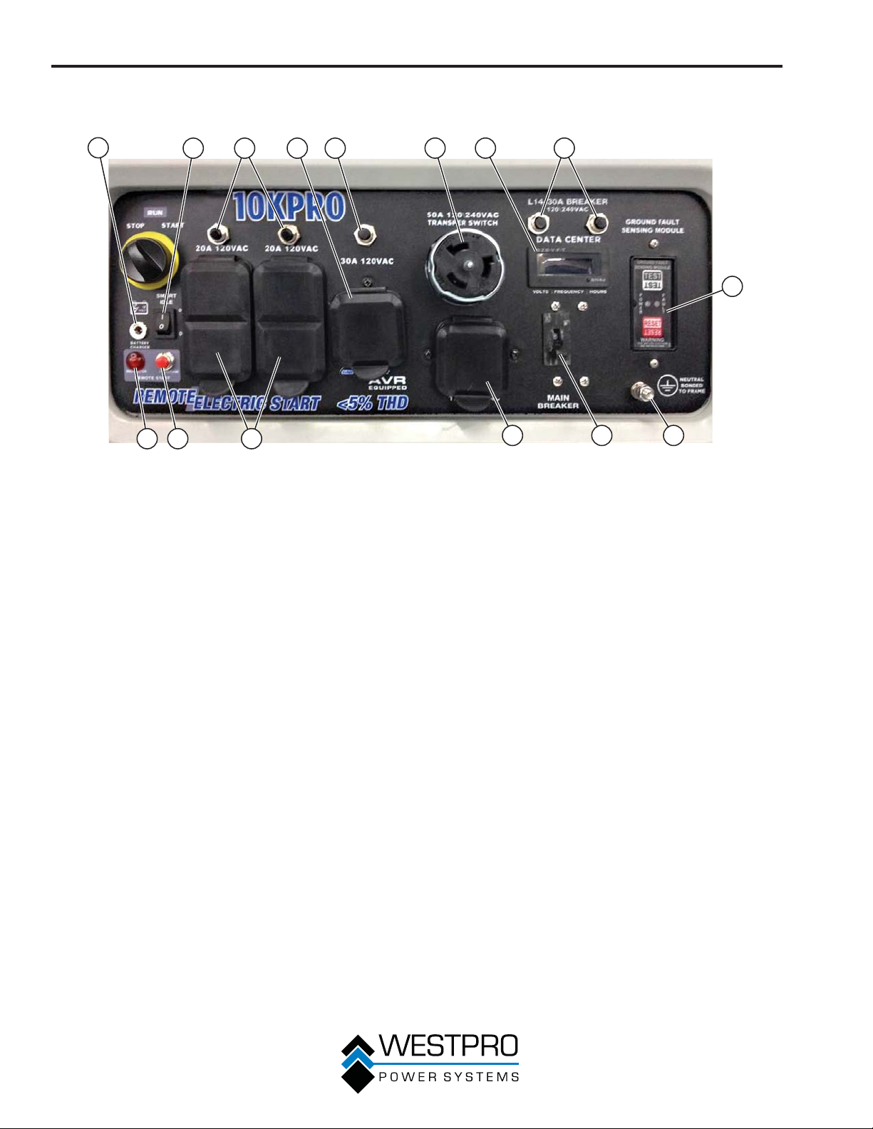
CARACTERÍSTICAS
CARACTERÍSTICAS DEL TABLERO DE CONTROL – 10KPRO
1
2
3 54
1415 13
Figura 12 – Características del tablero de control
1 - Puerto del cargador de la batería: Enchufe el
cargador de CA de 120 V a este terminal para
cargar la batería del generador.
2 - Control al ralentí bajo: Con el interruptor al
ralentí inteligente en la posición ON (I), si no
hay carga para ninguno de los tomacorrientes
durante 5 segundos o más, la velocidad del
motor disminuirá a 1800 RPM. Si se aplica
una carga a cualquiera de los tomacorrientes,
la velocidad del motor automáticamente
aumentará a 3600 RPM. Con el interruptor al
ralentí inteligente en la posición OFF (O), el
motor constantemente funcionará a 3600 RPM.
3 - Disyuntores de 20 amperios: Cada disyuntor
limita la corriente que se puede suministrar a
través de los tomacorrientes duplex de 120
voltios a 20 amperios.
4 - Tomacorriente de giro de seguridad de 120
Voltios, 30 Amperios: El tomacorriente puede
suministrar 120 V de potencia de salida hasta 30
amperios.
5 - Disyuntores de 120 Voltios, 30 Amperios:
El disyuntor limita la corriente que se puede
suministrar a través del tomacorriente de 120
voltios hasta 30 amperios.
6 - Tomacorriente de giro de seguridad
de 120/240 voltios, de 50 amperios: El
tomacorriente puede brindar una salida de 120 V
o 240 V.
7 - Centro de datos: El centro de datos muestra el
voltaje, frecuencia y tiempo de funcionamiento
acumulado.
6 7 8
9
1112 10
8 - Disyuntores de 30 amperios 120/240 voltios:
El disyuntor limita la corriente que puede
suministrarse a través del tomacorriente de
120/240 voltios de salida hasta 30 amperios.
9 - Sensor de falla a tierra: El sensor escaneará
todos los tomacorrientes en el panel de
control para localizar una falla de tierra. Si se
detecta una falla de tierra de cualquiera de los
tomacorrientes, el sensor automáticamente
hace saltar al disyuntor principal.
10 - Terminal de tierra: El terminal de tierra se usa
para conectar el generador a tierra.
11 - Disyuntor principal: El disyuntor principal
controla la potencia de salida total de todos los
tomacorrientes para proteger al generador.
12 - Tomacorriente de giro de seguridad de
120/240 Voltios, 30 Amperios: (NEMA L14-30):
El tomacorriente puede suministrar 120 V o 240
V de potencia de salida hasta 30 amperios.
13 - Tomacorrientes dúplex de 20 amperios, 120
voltios: Cada tomacorriente puede llevar un
máximo de 20 amperios en un tomacorriente
único o una combinación de todos los
tomacorrientes.
14 - Botón de programación de arranque remoto:
Utilice este botón junto con el llavero para
programar el generador para arrancarlo de
manera remota.
15 - Luz indicadora de arranque remoto: La luz se
encenderá o parpadeará en función del estado
del sistema de arranque remoto.
20
Page 73
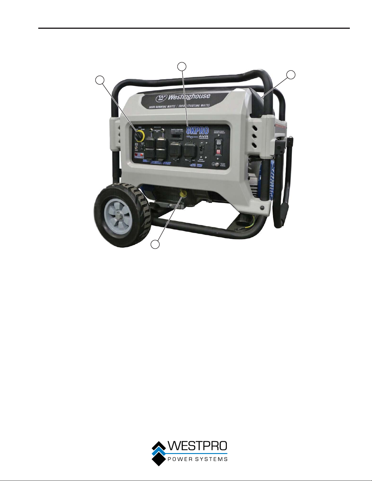
CARACTERÍSTICAS
CARACTERÍSTICAS GENERALES DEL GENERADOR – 8KPRO
2
1
4
1 -
Interruptor de control del motor: Enciende y
apaga el motor.
2 -
Panel de control: Contiene los disyuntores y
los tomacorrientes.
3
Figura 13
3 - Tapón de llenado/varilla de medición del
aceite: Se deben extraer para agregar y
controlar el aceite.
4 -
Indicador de combustible: Indica el nivel de
combustible.
21
Page 74
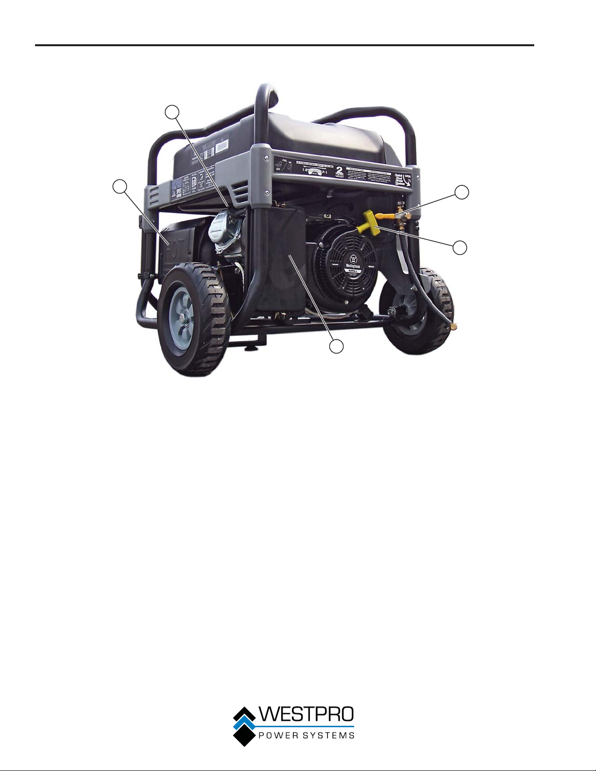
CARACTERÍSTICAS
2
1
1 -
Silenciador: Evite el contacto hasta que el
motor se enfríe.
2 - Capuchón (cable) de la bujía: Se debe quitar
cuando se realiza el mantenimiento del motor o
de la bujía.
3 - Válvula de drenaje rápido: Úsela para drenar
contaminantes del depósito de combustible.
3
4
5
Figura 14
4 - Manija de retroceso: Se usa para arrancar el
generador de forma manual.
5 - Cubierta del filtro de aire: Debe quitarse para
realizar el mantenimiento del filtro de aire.
22
Page 75
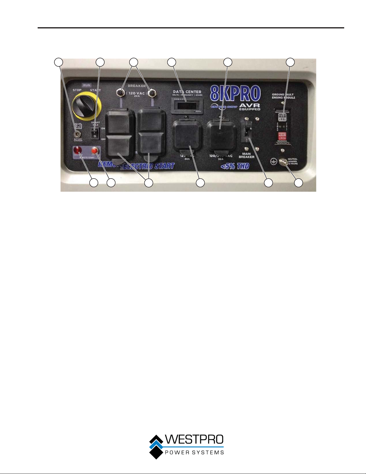
CARACTERÍSTICAS
CARACTERÍSTICAS DEL TABLERO DE CONTROL – 8KPRO
1
2
12 11
1 - Puerto del cargador de la batería: Enchufe el
cargador de CA de 120 V a este terminal para
cargar la batería del generador.
2 - Control al ralentí bajo: Con el interruptor al
ralentí inteligente en la posición ON (I), si no
hay carga para ninguno de los tomacorrientes
durante 5 segundos o más, la velocidad del
motor disminuirá a 1800 RPM. Si se aplica
una carga a cualquiera de los tomacorrientes,
la velocidad del motor automáticamente
aumentará a 3600 RPM. Con el interruptor al
ralentí inteligente en la posición OFF (O), el
motor constantemente funcionará a 3600 RPM.
3 - Disyuntores de 20 amperios: Cada disyuntor
limita la corriente que se puede suministrar a
través de los tomacorrientes duplex de 120
voltios a 20 amperios.
4 - Centro de datos: El centro de datos muestra el
voltaje, frecuencia y tiempo de funcionamiento
acumulado.
5 - Tomacorriente de giro de seguridad de
120/240 Voltios, 30 amperios (NEMA L14-30):
El tomacorriente puede suministrar 120 V o 240
V de potencia de salida hasta 30 amperios.
3 4 5 6
10
Figura 15 – Características del tablero de control
89 7
6 - Sensor de falla a tierra: El sensor escaneará
todos los tomacorrientes en el panel de
control para localizar una falla de tierra. Si se
detecta una falla de tierra de cualquiera de los
tomacorrientes, el sensor automáticamente
hace saltar al disyuntor principal.
7 - Terminal de tierra: El terminal de tierra se usa
para conectar el generador a tierra.
8 - Disyuntor principal: El disyuntor principal
controla la potencia de salida total de todos los
tomacorrientes para proteger al generador.
9 - Tomacorriente de giro de seguridad de 120
Voltios, 30 Amperios: El tomacorriente puede
suministrar 120 V de potencia de salida hasta 30
amperios.
10 - Tomacorrientes dúplex de 20 amperios, 120
voltios: Cada tomacorriente puede llevar un
máximo de 20 amperios en un tomacorriente
único o una combinación de todos los
tomacorrientes.
11 - Botón de programación de arranque remoto:
Utilice este botón junto con el llavero para
programar el generador para arrancarlo de
manera remota.
12 - Luz indicadora de arranque remoto: La luz se
encenderá o parpadeará en función del estado
del sistema de arranque remoto.
23
Page 76
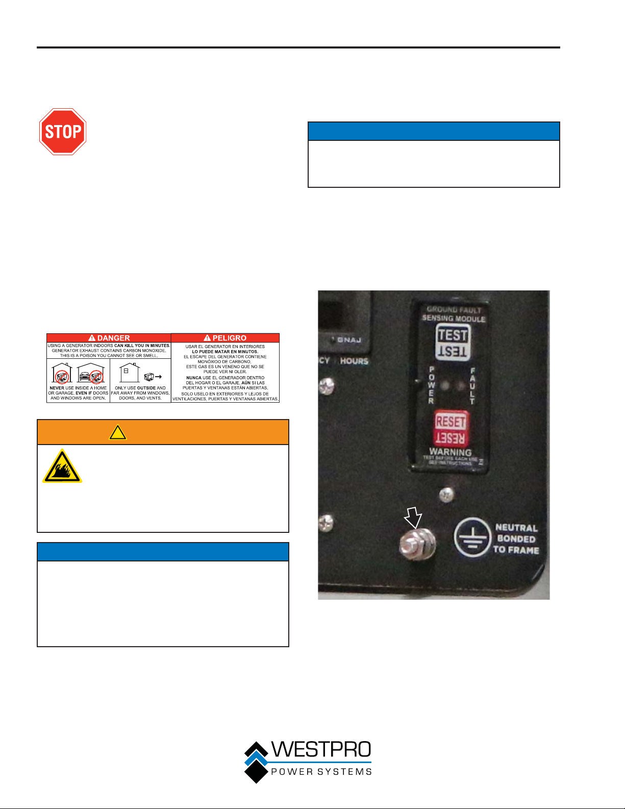
FUNCIONAMIENTO
ANTES DE ENCENDER EL
GENERADOR
Antes de arrancar el generador, analice
Seguridad en página 7.
Elección de la ubicación – Antes de poner en marcha el
generador, evite los peligros relacionados con el escape y la
ubicación, para lo cual debe verificar:
x Que se haya seleccionado una ubicación para operar el
generador que sea en exteriores y esté bien ventilada.
x Que se haya seleccionado una ubicación con una
superficie nivelada y sólida sobre la cual colocar el
generador.
x Que se haya seleccionado una ubicación que esté al
menos a 6 pies (1,8 metros) de cualquier edificio, otros
equipos o materiales combustibles.
x Si el generador está ubicado cerca de un edificio,
compruebe que no esté ubicado cerca de ventanas,
puertas y/o ventilaciones.
No debe haber cargas conectadas – Compruebe que el
generador no tenga cargas conectadas antes de encenderlo.
Para asegurar que no haya cargas conectadas, desenchufe
los prolongadores eléctricos que estén enchufados en los
receptáculos del panel de control.
AVISO
Si se enciende el generador con cargas aplicadas al
mismo, durante el breve período de puesta en marcha
podrían dañarse los artefactos que se accionan con el
generador.
Conexión a tierra del generador – El Código Eléctrico
Nacional (NEC, en inglés), así como numerosos códigos
eléctricos locales, exigen que se conecte el generador a
tierra antes de su operación. Antes de poner en marcha
el generador, compruebe que esté conectado a tierra
conectando el terminal de tierra del panel de control (vea la
Figura 16) a tierra usando alambre de cobre (10 AWG como
mínimo). Consulte a un electricista calificado para conocer los
requisitos de conexión a tierra locales.
!
ADVERTENCIA
Opere siempre el generador sobre una
superficie nivelada. Si se coloca un
generador sobre superficies que no están
niveladas puede tumbarse, derramando
combustible y aceite. El combustible
derramado puede encenderse si entra en
contacto con una fuente de ignición como
una superficie muy caliente.
AVISO
Sólo debe operar el generador sobre una superficie sólida
y nivelada. La operación de un generador sobre una
superficie en la que hay materiales sueltos como arena o
recortes de césped puede hacer que ingresen residuos al
generador que podrían:
• Obstruir las ventilaciones de refrigeración
• Obstruir el sistema de admisión de aire
Clima – Nunca opere su generador en exteriores durante
lluvia, nieve o cualquier combinación de condiciones
climáticas que pudieran producir la acumulación de humedad
sobre, dentro o alrededor del generador.
Superficie seca – Opere siempre el generador sobre una
superficie seca, libre de humedad.
Figura 16 – Terminal de conexión a tierra del panel de control
24
Page 77
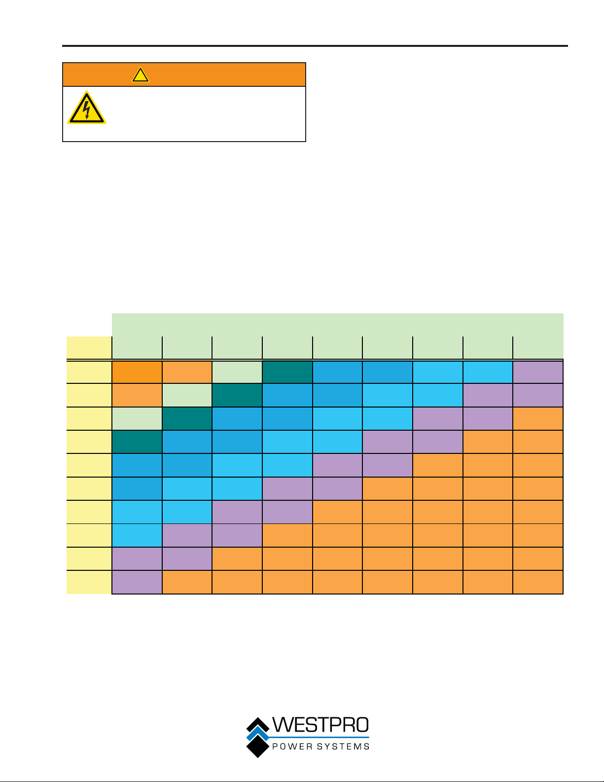
!
ADVERTENCIA
Asegúrese de que el generador esté
correctamente conectado a tierra antes
de usarlo. El generador se debe conectar
a tierra para evitar descargas eléctricas
causadas por artefactos defectuosos.
CABLE DE SUMINISTRO
Usar cables prolongadores
Westpro Power Systems no asume responsabilidad alguna
por el contenido de esta tabla. El uso de esta tabla es
exclusiva responsabilidad del usuario. La presente tabla está
diseñada para consulta únicamente. No se garantiza que
los resultados obtenidos mediante el uso de esta tabla sean
correctos ni que sean de aplicación para todas las situaciones
ya que el tipo y la construcción de los prolongadores son
altamente variables. Controle siempre las normativas locales
y consulte a un electricista matriculado antes de instalar o
conectar un artefacto eléctrico.
Calibre del cable del prolongador
FUNCIONAMIENTO
Longitud del prolongador (pies)
Amps10203040506080100120
5 20 18 16 14 12 12 10 10 8
10 18 16 14 12 12 10 10
88
15 16 14 12 12 10 10 8 8 6
20 14 12 12 10 10
8866
25 1212101088666
30 121010886666
35 10108866666
40 1088666
---
45 88666----
50 8666-----
25
Page 78
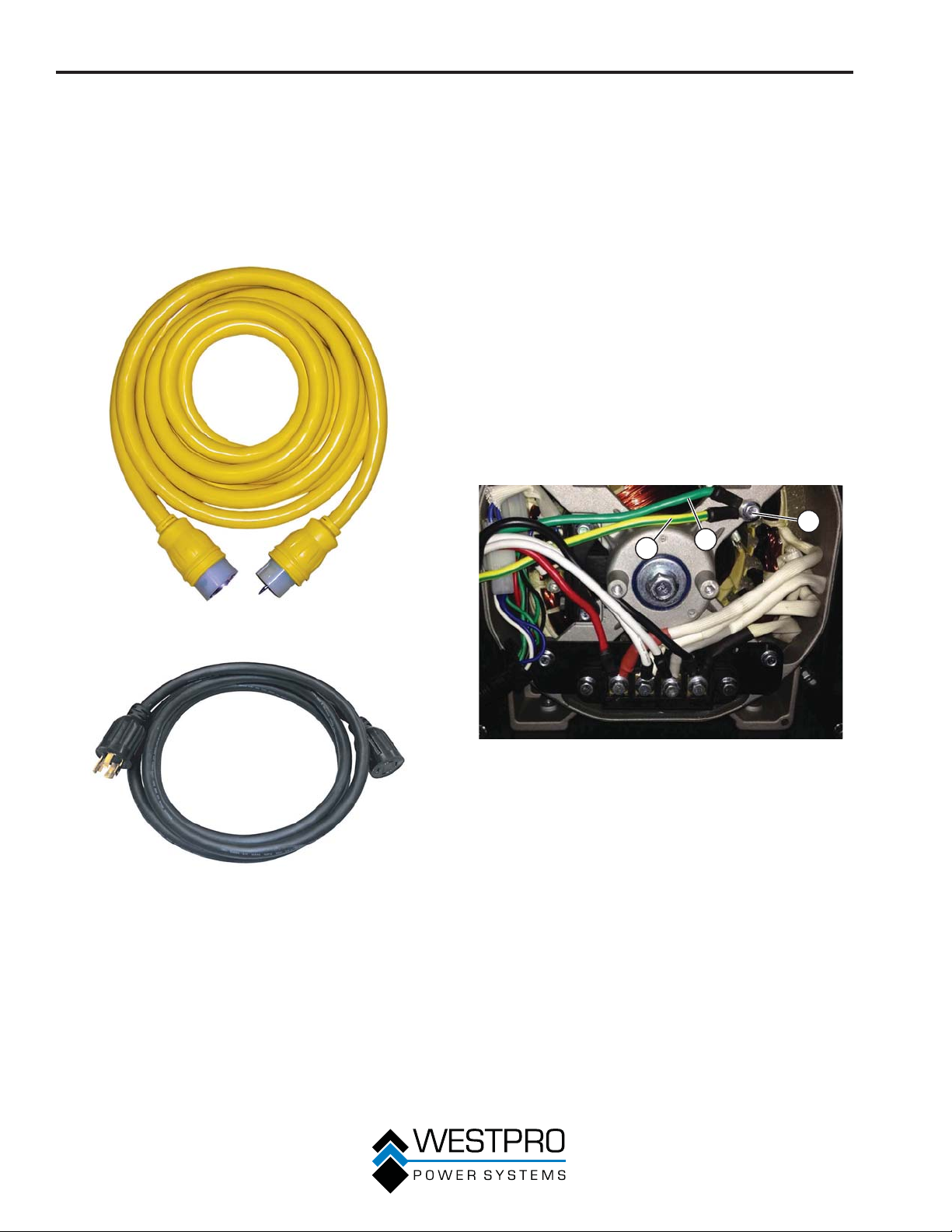
FUNCIONAMIENTO
Cable interruptor de transferencia
El cable interruptor de transferencia, 10KPRO N.° de pieza
210051 y 8KPRO N.° de pieza 210075, es un accesorio
opcional para el generador portátil. Se utiliza para conectar el
tomacorriente de 50 amperios del 10KPRO y el tomacorriente
de 30 amperios del 8KPRO del generador hasta el interruptor
de transferencia. Si su interruptor de transferencia no viene
con un cable interruptor de transferencia, pida el cable a
Westpro Power.
CONEXIONES DEL
INTERRUPTOR DE
TRANSFERENCIA
El generador Westinghouse está cableado con el neutro
conectado a tierra. Si está conectando su generador a un
interruptor de transferencia, el electricista primero debe
determinar qué tipo de interruptor de transferencia se usa.
Los interruptores de transferencia para este equipo son tipos
de dos o tres polos.
Un interruptor de transferencia de dos polos no cambiará el
neutro del generador al panel de servicio. Esto significa que
el generador será conectado a tierra a un panel de servicio.
Para usar el generador con interruptores de transferencia
de dos polos, el electricista necesitará cambiar el neutro de
conectado a flotante.
Extraiga el tornillo a tierra de los cables (vea la Figura 19).
Para aislarla, envuelva el terminal del cable verde con la cinta
aislarlo. Una con cinta el cable verde al cable amarillo/verde
de manera que no pueda tener contacto con partes móviles.
Vuelva a conectar a tierra el cable amarillo/verde con el
tornillo a tierra.
1
3
2
Figura 17 – Cable interruptor de transferencia, 10KPRO
Figura 18 – Cable interruptor de transferencia, 8KPRO
Figura 19 – Cable de conexión
1 - Tornillo a tierra
2 - Cable verde
3 - Cable amarillo/
verde
26
Page 79
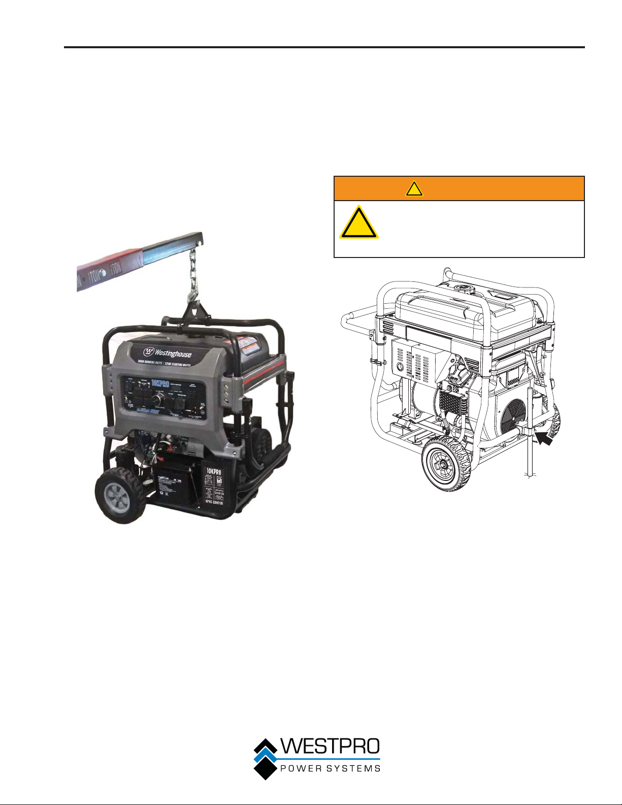
FUNCIONAMIENTO
SOPORTE DE ELEVACIÓN
1. Antes de elevar el generador, revise el soporte y
asegúrese de que esté bien sujeto al generador. No eleve
el generador a menos que el soporte de elevación esté
bien sujeto.
2. Enganche una cadena o cuerda alrededor del ojo del
soporte de elevación y asegúrese de que esté bien
sujeto.
3. Conecte un dispositivo de elevación adecuado a la
cadena o cuerda.
4. Levante el generador un poco para garantizar que se
esté levantando derecho y nivelado. Ajuste el soporte si
fuera necesario para que se eleve correctamente.
ANCLAJE DEL GENERADOR
El generador debe usarse en una superficie plana y nivelada
siempre que sea posible. Si el sitio de trabajo en particular
requiere que el generador se use en un terreno irregular,
debe anclarse el generador. Inserte una estaca o barra de
refuerzo a través del soporte de anclaje en el bastidor (
Figura 21). Conduzca la estaca hasta el suelo para asegurar
el generador y evitar que se mueva. El anclaje es estándar en
el 10KPRO y opcional en el 8KPRO.
!
ADVERTENCIA
Anclar el generador a tierra no conecta
eléctricamente a tierra el generador. Para
!
lograr una conexión eléctrica a tierra
adecuada del generador, vea Conectar a
tierra el generador en la página 24.
vea la
Figura 21 – Soporte de anclaje
Figura 20 – Soporte de elevación
27
Page 80
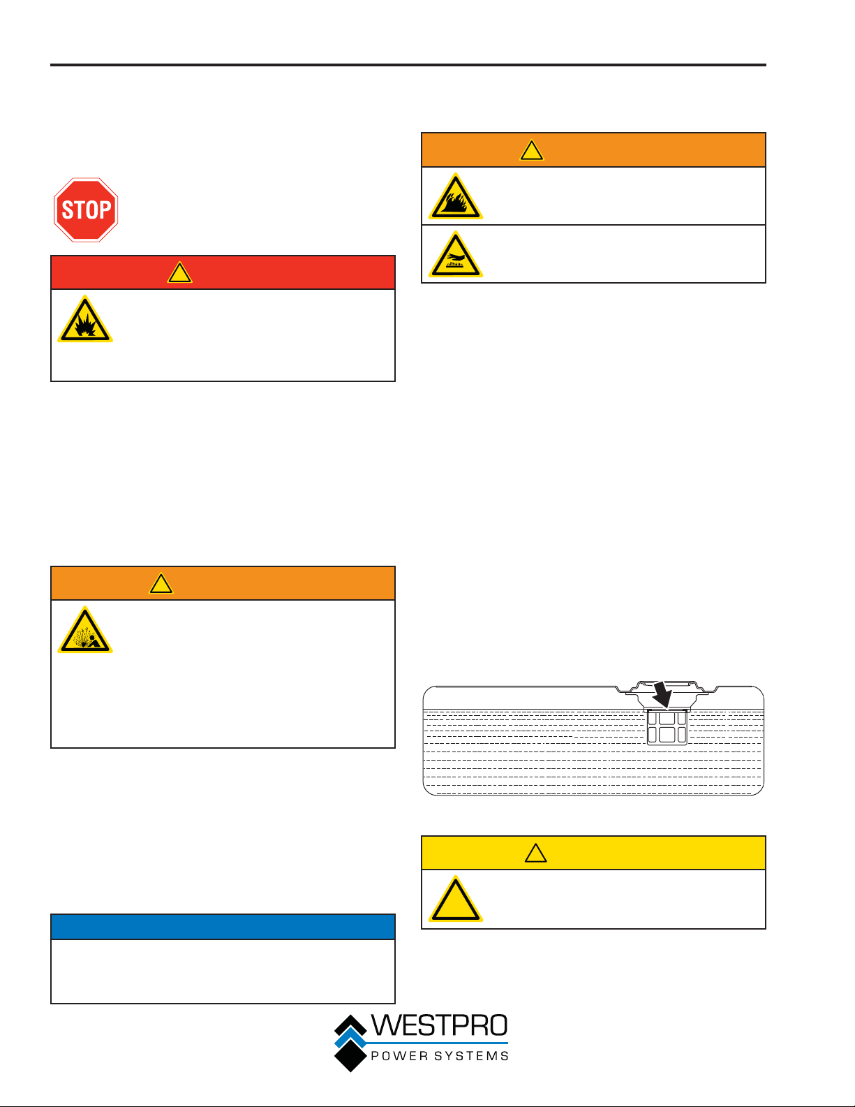
FUNCIONAMIENTO
PROCEDIMIENTO PARA
AGREGAR/CONTROLAR EL
COMBUSTIBLE Y LOS LÍQUIDOS
DEL MOTOR
Antes de agregar/controlar el
combustible y los líquidos del motor,
revise Seguridad en la página 7.
!
PELIGRO
Si se carga el depósito de combustible
con gasolina mientras el generador está
en marcha, se pueden provocar pérdidas
de gasolina que pueden entrar en contacto
con superficies calientes que pueden
encender la gasolina.
Antes de encender el generador, controle siempre el nivel de:
x Aceite de motor
x Gasolina en el depósito de combustible
Después de encender el generador y de que se caliente
el motor, no es seguro agregar gasolina al depósito de
combustible ni aceite de motor al motor mientras el motor
está en funcionamiento o mientras el motor y el silenciador
están calientes.
Procedimiento para controlar y/o
agregar el aceite para motor
!
ADVERTENCIA
La presión interna puede acumularse en el
cárter del motor mientras el motor está en
marcha. Si se extrae la varilla de medición
de aceite mientras el motor está caliente,
se puede salpicar aceite extremadamente
caliente fuera del cárter que puede producir
quemaduras graves en la piel. Deje que se
enfríe el aceite del motor durante varios
minutos antes de extraer la varilla de
medición de aceite.
Procedimiento para agregar gasolina al
depósito de combustible
!
ADVERTENCIA
Nunca haga la recarga de combustible
del generador mientras el motor está en
marcha.
Siempre debe apagar el motor y dejar que
el generador se enfríe antes de recargar
combustible.
Gasolina requerida – Sólo debe usar gasolina que cumpla
con los siguientes requisitos:
x Gasolina sin plomo únicamente
x Gasolina con etanol agregado hasta un máximo del 10%
x Gasolina con 87 de octanaje o superior
Procedimiento para cargar el depósito de combustible –
Siga los pasos a continuación para cargar el depósito de
combustible:
1. Apague el generador.
2. Permita que el generador se enfríe de manera que toda
la superficie del silenciador y el motor esté fresca al tacto.
3. Traslade el generador a una superficie plana.
4. Limpie la zona que rodea al tapón de combustible.
5. Quite el tapón de combustible girándolo en sentido
contrario a las agujas del reloj.
6. Agregue gasolina lentamente dentro del depósito
de combustible. Tenga mucho cuidado de no llenar
el depósito en exceso. El nivel de gasolina NO debe
superar la base del cuello de llenado (vea la Figura 22).
7. Instale el tapón de combustible girándolo en el sentido
de las agujas del reloj hasta que se escuche un clic que
indica que el tapón está completamente instalado.
La unidad como se envía no contiene aceite en el motor.
Debe agregar aceite del motor antes de encender el
generador por primera vez. Vea Procedimiento para
controlar el aceite del motor – 10KPRO en la página 35,
Procedimiento para controlar el aceite del motor – 8KPRO
en la página 36, Procedimiento para agregar el aceite
del motor – 10KPRO en la página 36 y Procedimiento
para agregar el aceite del motor – 8KPRO en la página
37 para obtener instrucciones sobre cómo controlar el
nivel de aceite del motor y sobre el procedimiento para
agregar aceite al motor.
AVISO
El generador no contiene aceite de motor cuando se
envía. Si se intenta encender el motor sin agregarle aceite
de motor, se pueden dañar de forma permanente los
componentes internos del motor.
28
Figura 22 – Nivel máximo de carga de gasolina
!
PRECAUCIÓN
Evite el contacto prolongado de la piel con
la gasolina. Evite respirar durante períodos
!
prolongados los vapores de la gasolina.
Page 81
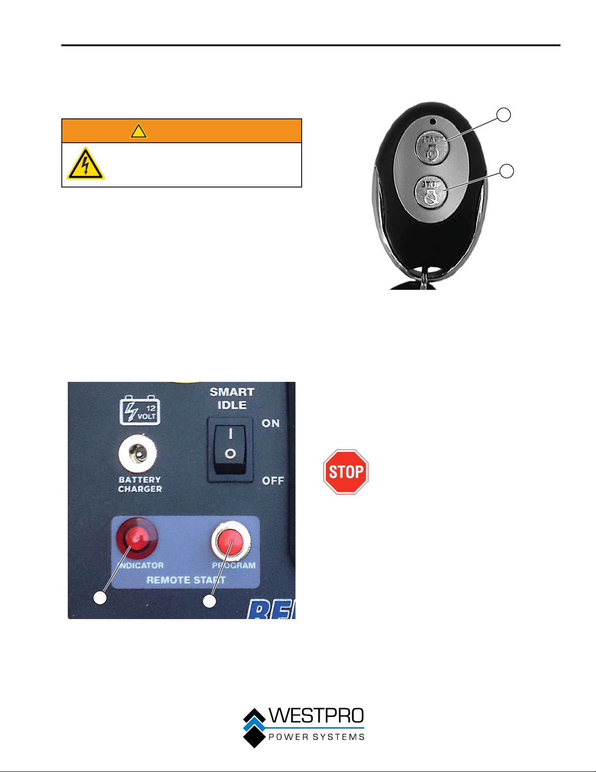
FUNCIONAMIENTO
PROGRAMACIÓN DEL
GENERADOR PARA EL
ARRANQUE REMOTO
!
ADVERTENCIA
Compruebe siempre que la zona que
rodea al generador esté despejada de
observadores antes de utilizar el arranque
remoto para arrancar el generador.
El generador se puede arrancar remotamente desde una
distancia de hasta 109 yardas (100 m) como máximo con
el llavero de arranque remoto si tiene baterías nuevas,
completamente cargadas. Cuando se reduce el estado
de carga de las baterías del llavero, también se reduce la
distancia para arrancar el generador.
Antes de poder arrancar el generador, se debe realizar
un procedimiento de arranque inicial de manera que el
generador y el llavero de control remoto se reconozcan
entre sí. Si se reemplaza el llavero, deberá realizar este
procedimiento con el llavero nuevo.
1. Gire el interruptor de control del motor hasta la posición
RUN (funcionamiento).
2. Oprima y mantenga apretado el botón de programación
del tablero de control (vea la Figura 23) durante 3
segundos. Se encenderá la luz indicadora de arranque
remoto.
3. Oprima el botón de detención del llavero de arranque
remoto (vea la Figura 24). La luz indicadora parpadeará
una vez y luego permanecerá encendida.
1
2
Figura 24 – Llavero de arranque remoto
1 - Botón de
arranque
4. Oprima el botón de arranque del llavero de arranque
remoto. La luz indicadora parpadeará una vez y luego
permanecerá encendida.
5. Oprima y mantenga apretado el botón de programación
durante 3 segundos. Ahora la luz indicadora se apagará
al cabo de 3 segundos. Ahora el generador está
programado para arrancar de manera remota.
2 - Botón de
detención
1
Figura 23 – Programación del arranque remoto
1 - Luz indicadora
de arranque
remoto
2
2 - Botón de
programación de
arranque remoto
ENCENDIDO DEL GENERADOR
Antes de arrancar el generador, analice
Seguridad en página 7.
Antes de intentar encender el generador, verifique lo
siguiente:
x El motor está cargado con aceite del motor (consulte
Procedimiento para controlar el aceite del motor –
10KPRO en la página 35 y Procedimiento para controlar
el aceite del motor – 8KPRO en la página 36).
x El generador se ubica en un lugar adecuado (vea Elección
de la ubicación en la página 24).
x El generador está sobre una superficie seca (vea Clima y
Superficie seca en la página 24).
x Se desconectan todas las cargas del generador (vea No
debe haber cargas conectadas en la página 24).
x El generador está adecuadamente conectado a tierra (vea
Conexión a tierra del generador en la página 24).
x El sensor de falla a tierra funciona correctamente (vea
Probar el sensor de falla a tierra en la página 46).
29
Page 82
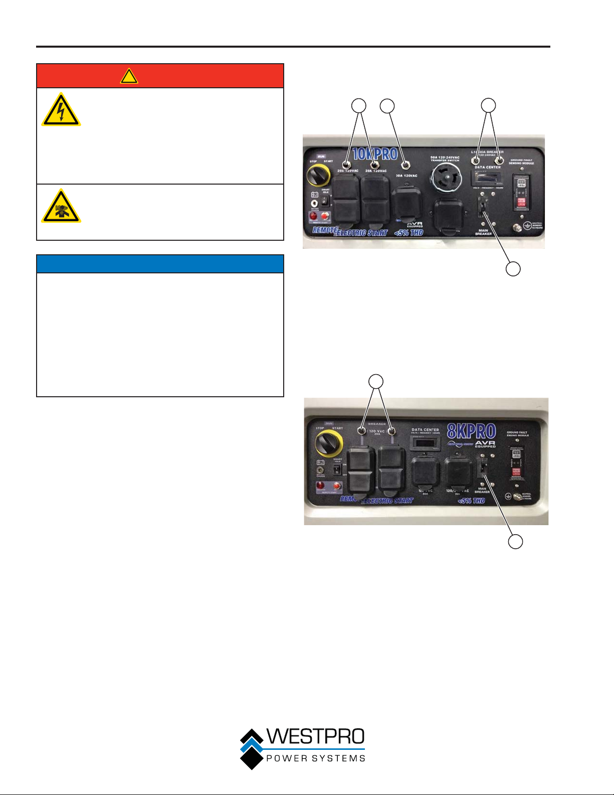
FUNCIONAMIENTO
!
PELIGRO
Nunca use el generador en lugares
mojados o húmedos. Nunca exponga el
generador a lluvia, nieve, rociado de agua
o agua estancada durante el uso. Proteja
el generador de todas las condiciones
climáticas peligrosas. La humedad o el
hielo pueden causar un cortocircuito u otro
tipo de problema de funcionamiento en el
circuito eléctrico.
Nunca opere el generador en un lugar
cerrado. El escape del motor contiene
monóxido de carbono. Sólo debe operar
el generador en exteriores y alejado de
ventanas, puertas y ventilaciones.
2. Asegúrese de que los disyuntores estén activados
correctamente (vea la Figura 25 y la Figura 26).
1
2
3
AVISO
El motor cuenta con un interruptor de desconexión por
nivel bajo de aceite. Si el nivel del aceite es bajo, el motor
se apagará y no arrancará hasta que se cargue aceite
hasta el nivel adecuado.
Asegúrese de que el motor tenga el nivel de aceite
adecuado antes de usarlo. Si no se verifica que el motor
tenga el nivel de aceite adecuado se podría dañar el motor.
Desconecte todas las cargas del generador antes de
encenderlo. Si no se verifica que todas las cargas estén
desconectadas antes de encender el generador se podrían
dañar los artefactos que estén conectados.
1. Verifique que la batería esté bien instalada y que ambos
cables estén sujetados (vea Instalación de la batería en
la página 16).
Figura 25 – Disyuntores – 10KPRO
1 - Disyuntor de 120 V
2 - Disyuntor de 30
amperios, 120
voltios
1
4
3 - Disyuntor de 30
amperios, 120/240
voltios
4 - Disyuntor principal
2
30
Figura 26 – Disyuntores – 8KPRO
1 - Disyuntor de 120 V 2 - Disyuntor principal
Page 83
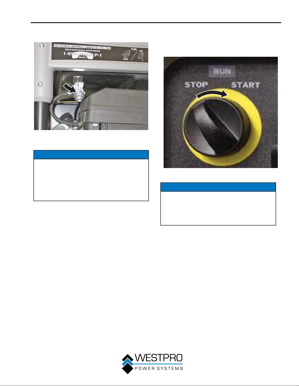
FUNCIONAMIENTO
3. Mueva la válvula de cierre de combustible a la posición
ON (encendido) (vea la Figura 27).
Figura 27 – Válvula de cierre del combustible en la posición
ON (encendido)
AVISO
El presente generador cuenta con un cebador
automático para el arranque. Dicho sistema está
siempre encendido y no se lo puede apagar. No intente
ajustar el cebador automático ni realizar ningún otro
ajuste en el carburador. La manipulación indebida del
sistema de cebador automático puede anular la garantía.
Consulte en un centro servicio Westinghouse autorizado
para obtener más información.
4. Gire el interruptor de control del motor a la posición
START (arranque) hasta que arranque el motor. Después
de que se encienda el motor, suelte el interruptor de
control del motor; se moverá automáticamente a la
posición ON (encendido) (vea la Figura 28).
Figura 28 – Interruptor de control del motor
AVISO
Si no se suelta el interruptor de control del motor
después del encendido del motor, se podría dañar el
generador.
Nunca lleve el interruptor de control del motor hasta la
posición START (encendido) mientras el motor está en
marcha; esto podría dañar el generador.
OTA:N Si el motor no arranca después de 5 segundos,
OTA:N El generador de arranque está equipado con
31
suelte el interruptor de control del motor.
Deje que el generador quede inactivo durante
15 segundos y luego repita el paso 4. Si la
velocidad de arranque se reduce luego de cada
intento fallido, es posible que la batería no esté
bien cargada.
una función de carga de batería. Después
de que el motor esté en funcionamiento, se
suministra una pequeña carga a la batería a
través de los cables de la batería y se la recarga
lentamente.
Page 84
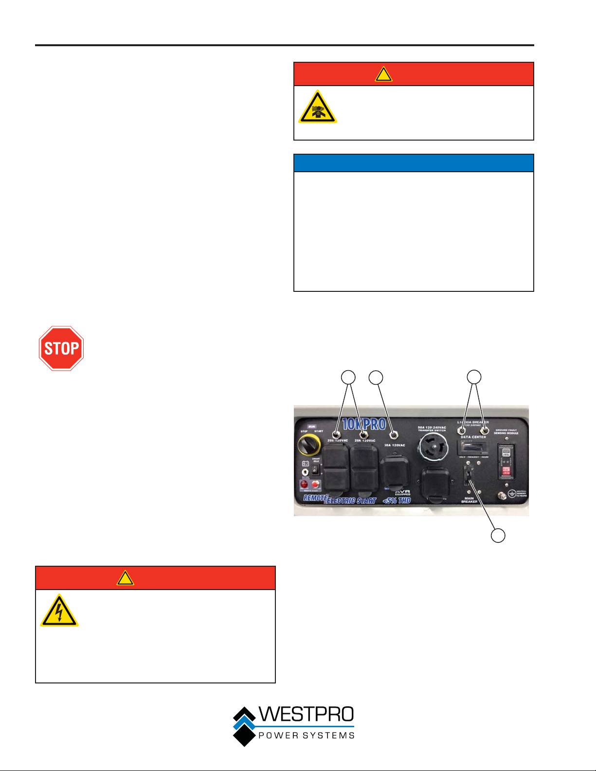
FUNCIONAMIENTO
DETENCIÓN DEL GENERADOR
Funcionamiento normal
Durante el funcionamiento normal, use los siguientes pasos
para detener el generador:
1. Retire las cargas conectadas de los receptáculos del
panel de control.
2. Deje que el generador funcione "sin carga" para reducir y
estabilizar las temperaturas del motor y del alternador.
3. Gire el interruptor de control del motor hasta la posición
OFF (apagado).
4. Cambie la válvula de cierre del combustible a la posición
OFF (apagado).
Durante una emergencia
Si surge una emergencia y se debe detener el generador
rápidamente, oprima el interruptor de control del motor hasta
la posición OFF (apagado) de inmediato.
ARRANQUE DEL GENERADOR
CON EL ARRANQUE REMOTO
Antes de arrancar el generador, analice
Seguridad en página 7.
!
PELIGRO
Nunca opere el generador en un lugar
cerrado. El escape del motor contiene
monóxido de carbono. Sólo debe operar
el generador en exteriores y alejado de
ventanas, puertas y ventilaciones.
AVISO
El motor cuenta con un interruptor de desconexión por
nivel bajo de aceite. Si el nivel del aceite es bajo, el motor
se apagará y no arrancará hasta que se cargue aceite
hasta el nivel adecuado.
Asegúrese de que el motor tenga el nivel de aceite
adecuado antes de usarlo. Si no se verifica que el motor
tenga el nivel de aceite adecuado se podría dañar el motor.
Desconecte todas las cargas del generador antes de
encenderlo. Si no se verifica que todas las cargas estén
desconectadas antes de encender el generador se podrían
dañar los artefactos que estén conectados.
1. Verifique que la batería esté bien instalada y que ambos
cables estén sujetados (vea Instalación de la batería en
la página 16).
2. Asegúrese de que los disyuntores estén correctamente
configurados (vea la Figura 29 y la Figura 30).
Antes de intentar encender el generador, verifique lo
siguiente:
x El motor está cargado con aceite del motor (consulte
Procedimiento para controlar el aceite del motor –
10KPRO en la página 35 y Procedimiento para controlar
el aceite del motor – 8KPRO en la página 36).
x El generador se ubica en un lugar adecuado (vea Elección
de la ubicación en la página 24).
x El generador está sobre una superficie seca (vea Clima y
Superficie seca en la página 24).
x Se desconectan todas las cargas del generador (vea No
debe haber cargas conectadas en la página 24).
x El generador está adecuadamente conectado a tierra (vea
Conexión a tierra del generador en la página 24).
x El sensor de falla a tierra funciona correctamente (vea
Probar el sensor de falla a tierra en la página 46).
!
PELIGRO
Nunca use el generador en lugares
mojados o húmedos. Nunca exponga el
generador a lluvia, nieve, rociado de agua
o agua estancada durante el uso. Proteja
el generador de todas las condiciones
climáticas peligrosas. La humedad o el
hielo pueden causar un cortocircuito u otro
tipo de problema de funcionamiento en el
circuito eléctrico.
1
2
Figura 29 – Disyuntores – 10KPRO
1 - Disyuntor de 120 V
2 - Disyuntor de 30
amperios, 120
voltios
3
4
3 - Disyuntor de 30
amperios, 120/240
voltios
4 - Disyuntor principal
32
Page 85
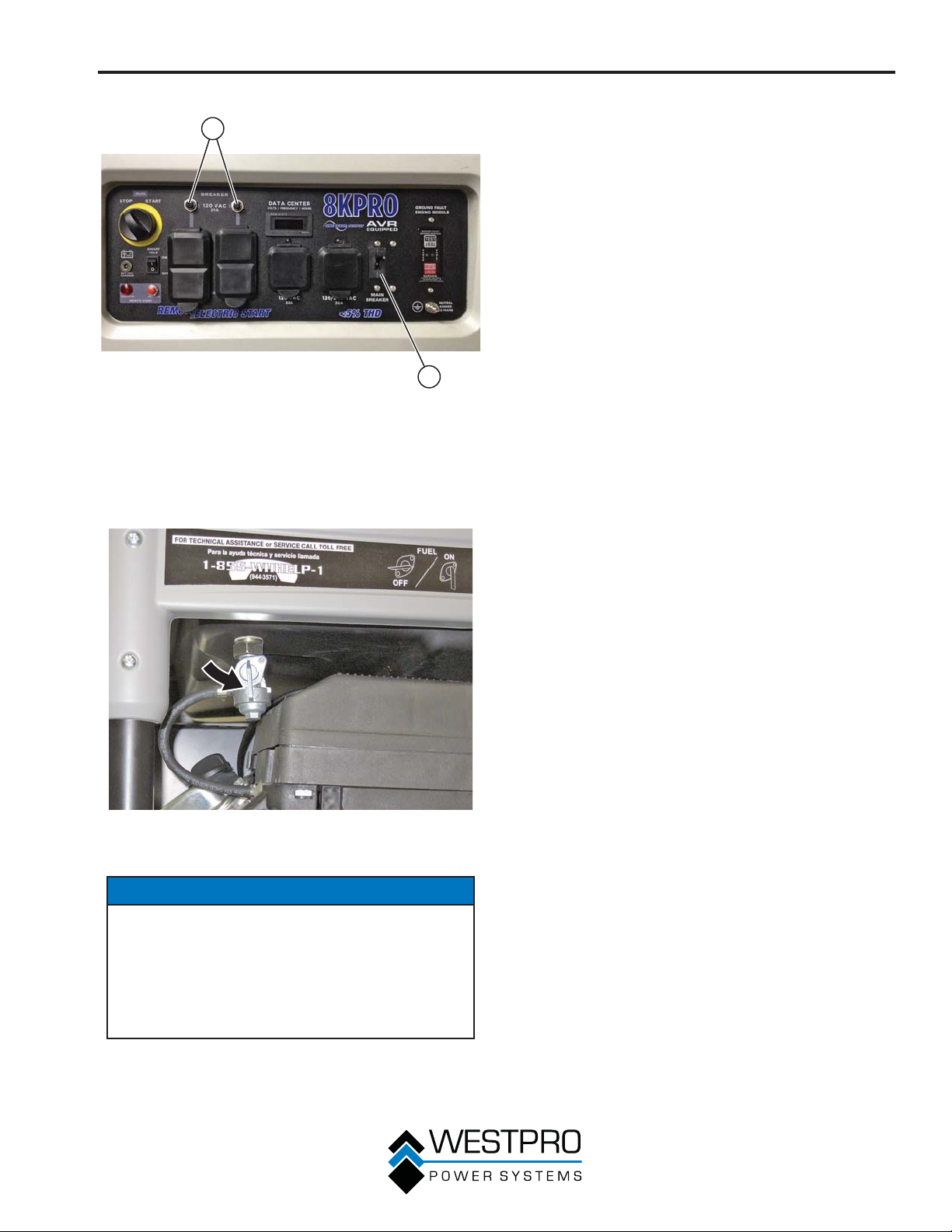
FUNCIONAMIENTO
4. Oprima el botón de arranque del llavero de arranque
1
remoto.
5. El generador girará durante 3 a 5 segundos y arrancará.
6. En el ciclo de arranque remoto, se programó un
retardo de calentamiento del motor. Después de que el
generador esté en marcha, se producirá un retardo de
potencia de salida eléctrica de 15 segundos.
7. Si el motor no arranca en el término de 3 a 5 segundos,
el motor intentará arrancar cinco veces más. Si el
generador no arranca, parpadea la luz indicadora de
arranque remoto.
8. Si el generador no arranca al cabo de un total de seis
intentos, se debe oprimir nuevamente el botón de
arranque del llavero para iniciar otro ciclo de seis intentos
de arranque.
2
Figura 30 – Disyuntores – 8KPRO
1 - Disyuntor de 120 V 2 - Disyuntor principal
3. Mueva la válvula de cierre de combustible a la posición
ON (encendido) (vea la Figura 31).
Figura 31 – Válvula de cierre del combustible en la posición
ON (encendido)
DETENCIÓN DEL GENERADOR
CON EL ARRANQUE REMOTO
1. Asegúrese de que no haya carga hacia ninguno de los
tomacorrientes del generador.
2. Oprima el botón de detención del llavero de arranque
remoto.
3. El motor funcionará durante 15 segundos más al pasar
por un ciclo de enfriamiento antes de apagarse.
AVISO
El presente generador está equipado con un cebador
automático para el arranque. Este sistema está siempre
encendido y no se lo puede apagar. No intente ajustar
el cebador automático ni realizar ningún otro ajuste en
el carburador. La manipulación indebida del sistema de
cebador automático puede anular la garantía. Consulte
a un centro de servicio Westinghouse autorizado para
obtener más información.
33
Page 86
MANTENIMIENTO
MANTENIMIENTO
Antes de realizar tareas de
mantenimiento del generador, analice
Seguridad en página 7 y los
siguientes mensajes de seguridad.
!
ADVERTENCIA
Extraiga de la bujía el capuchón de la
bujía de encendido para evitar encender
!
accidentalmente el generador durante el
mantenimiento. También desconecte los
cables de la batería (desconecte el cable
negativo (-) negro primero) y aleje los
cables de los terminales de la batería para
evitar formación de arcos eléctricos.
Deje que los componentes calientes
se enfríen al tacto antes de realizar los
procedimientos de mantenimiento.
La presión interna puede acumularse en el
cárter del motor mientras el motor está en
marcha. Si se extrae la varilla de medición
de aceite mientras el motor está caliente,
se puede salpicar aceite extremadamente
caliente fuera del cárter que puede producir
quemaduras graves en la piel. Deje que se
enfríe el aceite del motor durante varios
minutos antes de extraer la varilla de
medición de aceite.
Siempre debe realizar el mantenimiento
en una zona bien ventilada. La gasolina
y los vapores del combustible son
extremadamente inflamables y pueden
encenderse en ciertas condiciones.
!
PRECAUCIÓN
Evite que la piel esté en contacto con el
aceite del motor o la gasolina. El contacto
prolongado de la piel con el aceite del
motor o la gasolina puede ser perjudicial.
El contacto frecuente y prolongado con el
aceite del motor puede causar cáncer de
piel. Tome medidas de protección y utilice
vestimenta y equipos de protección. Lave
con agua y jabón toda la piel que haya
quedado expuesta.
Cronograma de mantenimiento
!
ADVERTENCIA
Si no se realiza un mantenimiento
periódico o no se realizan procedimientos
!
de mantenimiento el generador puede
funcionar mal y podría causar lesiones
graves o la muerte.
AVISO
Los intervalos del mantenimiento periódico varían
en función de las condiciones de funcionamiento del
generador. Si se usa el generador en condiciones
adversas, como con cargas elevadas sostenidas,
temperaturas elevadas o en entornos inusualmente
húmedos o con abundante polvo, será necesario hacer
un mantenimiento periódico más frecuente. Los intervalos
mencionados en el cronograma de mantenimiento se
deben tratar únicamente como una orientación general.
Es importante respetar el cronograma de mantenimiento
para mantener el generador en buenas condiciones de
funcionamiento. A continuación se incluye un resumen
de las tareas de mantenimiento según los intervalos de
mantenimiento periódicos.
Tabla 1: Cronograma de mantenimiento - Realizado por el propietario
Después de
Tareas de
mantenimiento
Antes de cada
uso
las primeras
20 horas o el
primer mes de
Después de 50
horas de uso o
cada 3 meses
Después de 100
horas de uso o
cada 6 meses
uso
Aceite de motor
Características
de refrigeración
Filtro de aire
Bujía de
encendido
1
Realice el mantenimiento con mayor frecuencia si se usa en entornos secos y donde abunda el polvo.
34
Controlar el nivel Cambiar Cambiar – –
Controlar/limpiar ––––
Controlar –
– – – Controlar/limpiar Sustituir
Inspeccione o
reemplace
1
– Sustituir
Después de 300
horas de uso o
todos los años
Page 87
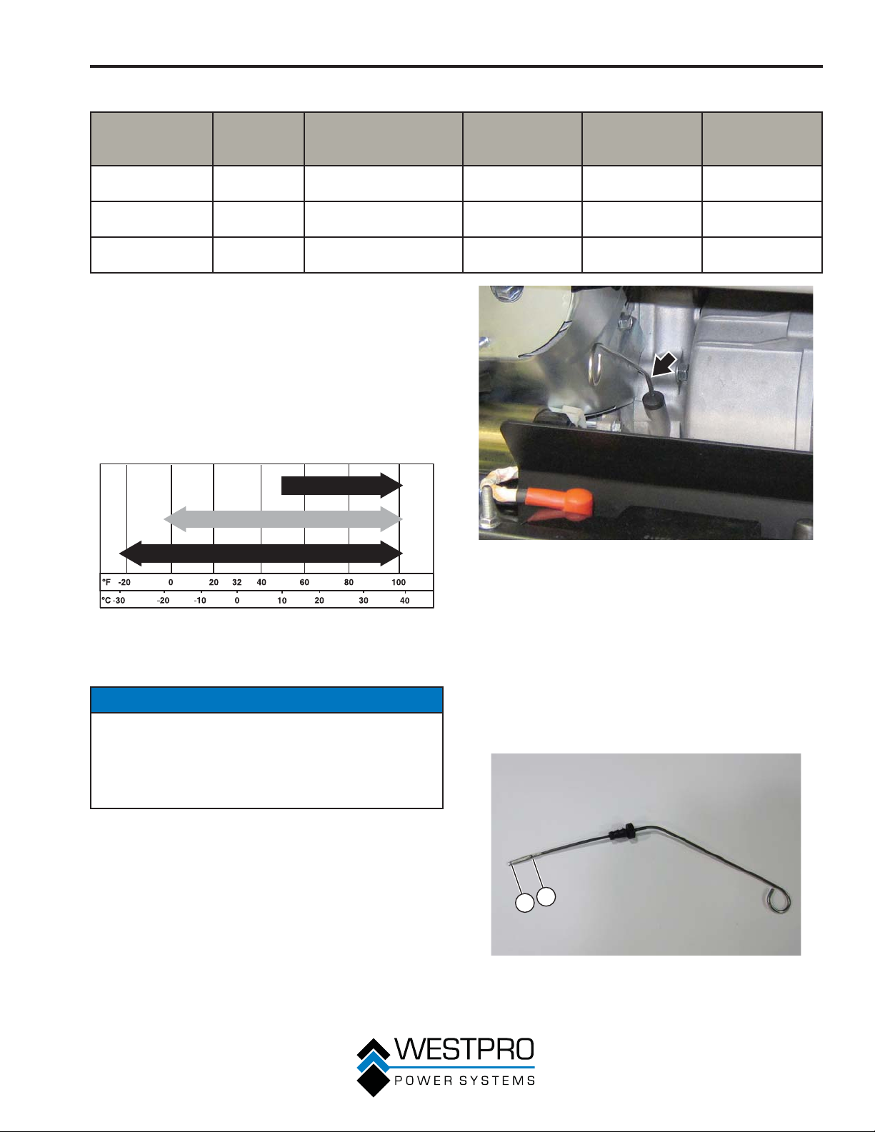
MANTENIMIENTO
Tabla 2: Cronograma de mantenimiento - Realizado por el Distribuidor autorizado de servicio Westinghouse
Tareas de
mantenimiento
Separación de la
válvula
Filtro de
combustible
Velocidad al
ralentí
Antes de
cada uso
– – – – Controlar/ajustar
– – – Controlar/limpiar –
– – – – Controlar/ajustar
Después de las
primeras 20 horas o
el primer mes de uso
MANTENIMIENTO DEL ACEITE
DEL MOTOR
Especificación del aceite del motor
1. Utilice únicamente el aceite de motor especificado en la
Figura 32.
2. Utilice únicamente el aceite de motor de 4 tiempos.
NUNCA UTILICE ACEITE DE MOTOR DE 2 TIEMPOS.
El aceite sintético es un sustituto aceptable para el aceite
convencional.
Después de 50
horas de uso o
cada 3 meses
Después de 100
horas de uso o
cada 6 meses
Después de 300
horas de uso o
todos los años
SAE 30
Conventional 10W-30
5W-30
Figura 32 – Aceite recomendado
Procedimiento para controlar el aceite
del motor – 10KPRO
AVISO
Mantenga siempre un nivel de aceite del motor adecuado.
Si no se mantiene el nivel de aceite del motor adecuado se
podría dañar gravemente el motor y/o acortar su vida útil.
Siempre use el aceite del motor especificado. Si no se
usa el aceite del motor especificado se puede acelerar el
desgaste del motor y/o acortar su vida útil.
Se debe controlar el aceite del motor antes de cada uso.
1. Siempre opere o mantenga el generador sobre una
superficie plana.
2. Detenga el motor si está en marcha.
3. Deje que el motor quede inactivo y se enfríe durante
varios minutos (deje que la presión del cárter se
equilibre).
4. Con una tela húmeda, limpie alrededor de la varilla de
medición de aceite.
5. Retire la varilla de medición de aceite (vea la Figura 33).
Figura 33 – Varilla de medición de aceite
6. Controle el nivel de aceite:
Cuando controle el nivel de aceite del motor, retire la
varilla de medición de aceite y límpiela. Inserte la varilla
por completo hacia adentro y luego retire y compruebe el
nivel de aceite en la varilla de medición.
x Nivel de aceite aceptable: El aceite es visible entre las
líneas H y L en la varilla de medición de aceite (vea la
Figura 34).
x Nivel de aceite bajo: el aceite está por debajo de la
línea L (bajo) de la varilla de medición de aceite.
2
1
Figura 34 – Control del nivel de aceite
1 - Línea de nivel de
aceite bajo
2 - Línea de nivel de
aceite alto
35
Page 88
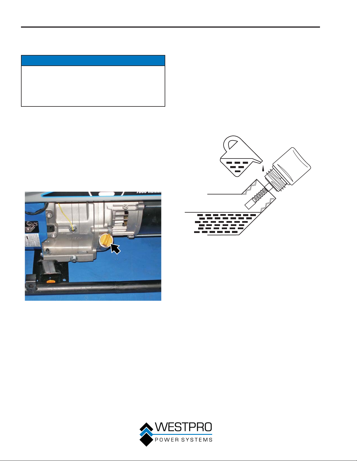
MANTENIMIENTO
Procedimiento para controlar el aceite
del motor – 8KPRO
AVISO
Mantenga siempre un nivel de aceite del motor adecuado.
Si no se mantiene el nivel de aceite del motor adecuado se
podría dañar gravemente el motor y/o acortar su vida útil.
Siempre use el aceite del motor especificado. Si no se
usa el aceite del motor especificado se puede acelerar el
desgaste del motor y/o acortar su vida útil.
Se debe controlar el aceite del motor antes de cada uso.
1. Siempre opere o mantenga el generador sobre una
superficie plana.
2. Detenga el motor si está en marcha.
3. Deje que el motor quede inactivo y se enfríe durante
varios minutos (deje que la presión del cárter se
equilibre).
4. Con una tela húmeda, limpie alrededor del tapón de
llenado/la varilla de medición del aceite.
5. Extraiga el tapón de llenado/la varilla de medición del
aceite (vea la Figura 35).
6. Controle el nivel de aceite:
Cuando controle el nivel de aceite, retire el tapón de
llenado/la varilla de medición del aceite y límpielos.
Enrosque el tapón de llenado/la varilla de medición del
aceite completamente y luego sáquelos para controlar el
nivel de aceite del tapón de llenado/la varilla de medición
del aceite.
x Nivel de aceite aceptable – se puede ver el aceite
sobre las rayas que hay entre las líneas H (alto) y L
(bajo) del tapón de llenado/la varilla de medición del
aceite (vea la Figura 36).
x Nivel de aceite bajo – el aceite está por debajo de
la línea L (bajo) del tapón de llenado/la varilla de
medición de aceite.
H
L
Figura 35 – Tapón de llenado/varilla de medición del aceite
Figura 36 – Control del nivel de aceite
Procedimiento para agregar el aceite
del motor – 10KPRO
1. Siempre opere o mantenga el generador sobre una
superficie plana.
2. Detenga el motor si está en marcha.
3. Deje que el motor quede inactivo y se enfríe durante
varios minutos (deje que la presión del cárter se
equilibre).
4. Limpie completamente alrededor del tapón de llenado de
aceite.
36
Page 89
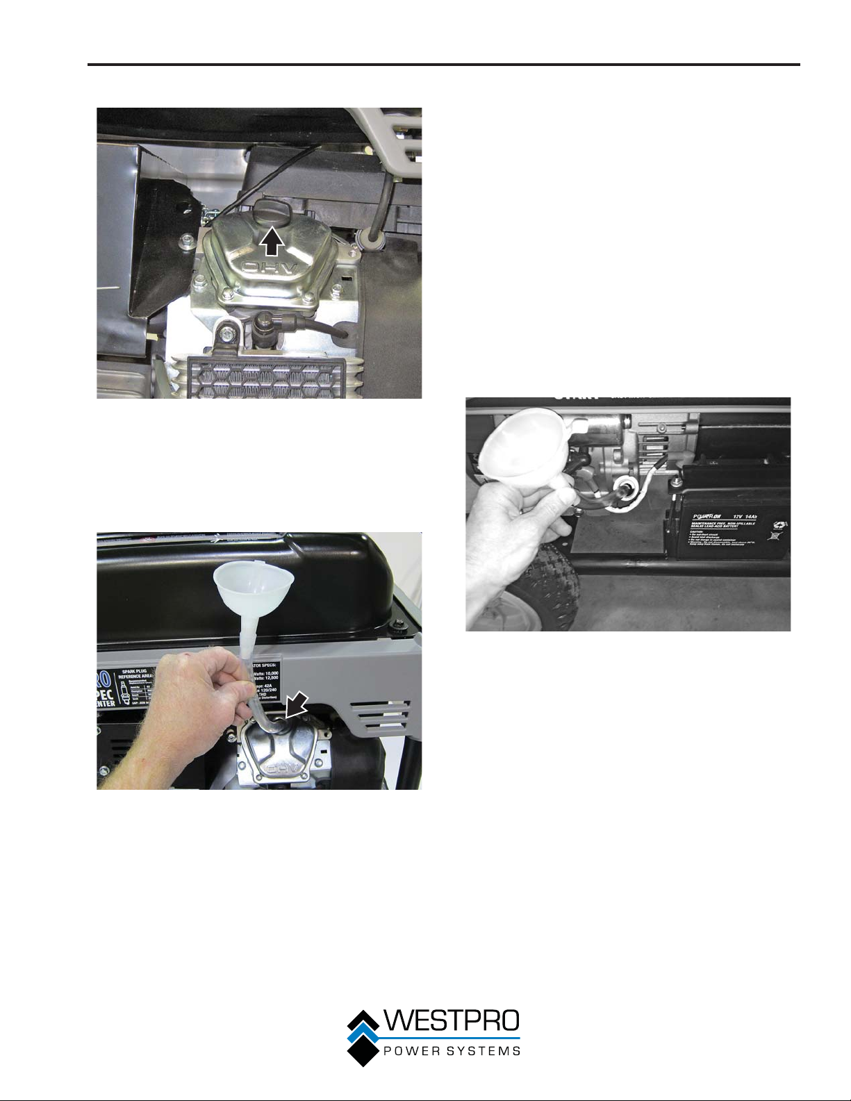
MANTENIMIENTO
5. Retire el tapón de llenado del aceite (vea la Figura 37).
Figura 37 – Tapón de llenado del aceite
6. Seleccione el aceite de motor correcto según lo
especificado en la Figura 32.
7. Usando el embudo y el tubo suministrado, agregue aceite
de motor lentamente al motor. Con frecuencia deténgase
para verificar el nivel y evitar llenar demasiado (vea la
Figura 38).
Procedimiento para agregar el aceite
del motor – 8KPRO
1. Siempre opere o mantenga el generador sobre una
superficie plana.
2. Detenga el motor si está en marcha.
3. Deje que el motor quede inactivo y se enfríe durante
varios minutos (deje que la presión del cárter se
equilibre).
4. Limpie completamente alrededor del tapón de llenado/la
varilla de medición del aceite.
5. Retire el tapón de llenado/la varilla de medición del
aceite y límpielos.
6. Seleccione el aceite de motor correcto según lo
especificado en la Figura 32.
7. Usando el embudo y el tubo suministrado, agregue aceite
de motor lentamente al motor. Con frecuencia deténgase
para verificar el nivel y evitar llenar demasiado (vea la
Figura 39).
Figura 38 – Procedimiento para agregar el aceite del motor
8. Continúe agregando aceite hasta que esté en el nivel
correcto. Vea Procedimiento para controlar el aceite del
motor – 10KPRO en la página 35.
Figura 39 – Procedimiento para agregar el aceite del motor
8. Continúe agregando aceite hasta que esté en el nivel
correcto. Vea Procedimiento para controlar el aceite del
motor – 8KPRO en la página 36.
Procedimiento para cambiar el aceite
del motor – 10KPRO
1. Pare el motor.
2. Deje que el motor quede inactivo y se enfríe durante
varios minutos (deje que la presión del cárter se
equilibre).
3. Coloque el platillo de aceite (o contenedor adecuado)
debajo del filtro de aceite y tapón de drenaje de aceite.
4. Con una tela húmeda, limpie completamente alrededor
del tapón de drenaje del aceite y el filtro de aceite.
5. Gire el filtro de aceite en sentido antihorario y retire el
filtro (vea la Figura 40).
37
Page 90
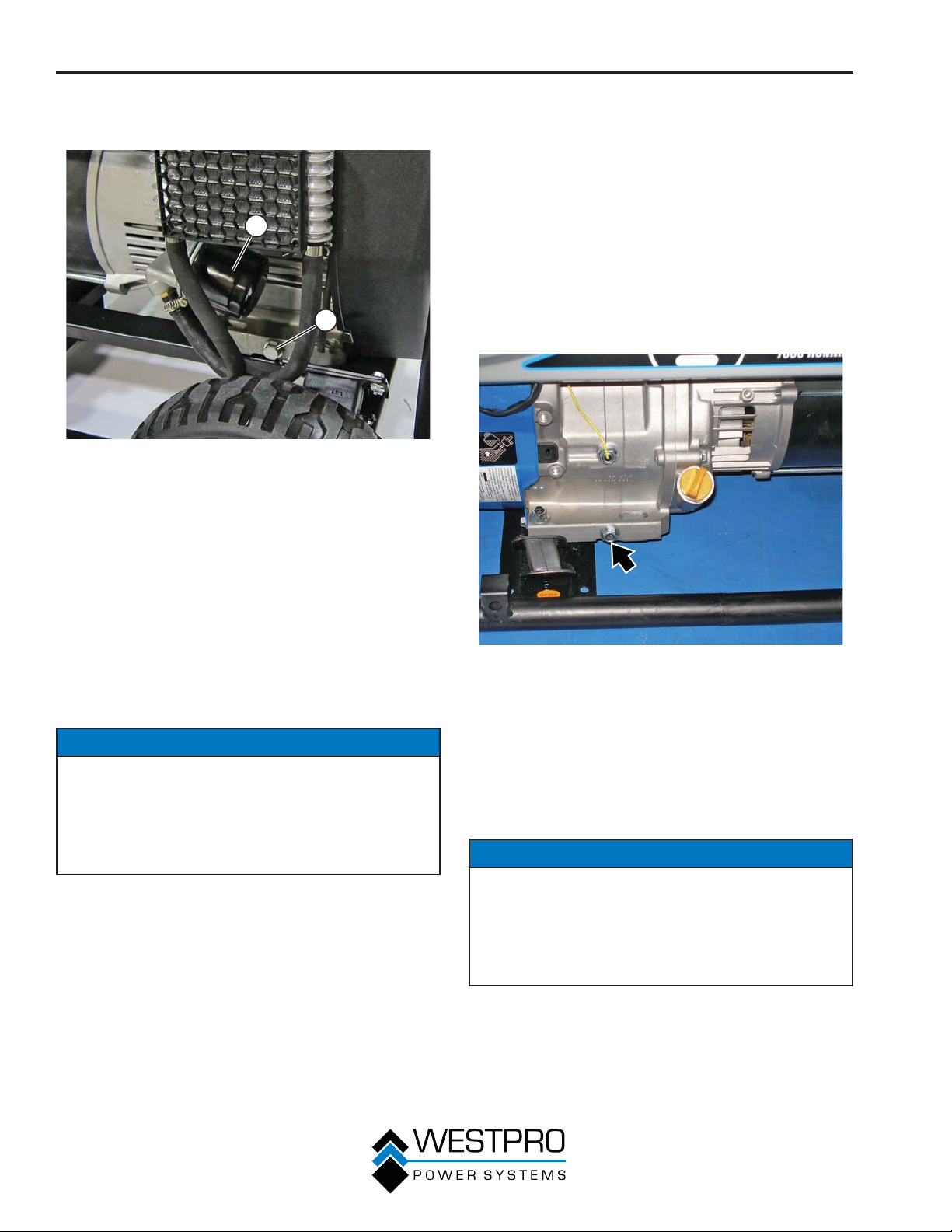
MANTENIMIENTO
6. Extraiga el tapón de drenaje del aceite (vea la Figura
40). Después de hacerlo, coloque el tapón de drenaje del
aceite sobre una superficie limpia.
1
2
Figura 40 – Filtro y tapón de drenaje del aceite
1 - Filtro de aire (Pieza
N° 180389)
7. Deje que se drene totalmente el aceite.
8. Coloque nuevamente el tapón de drenaje del aceite.
9. Aplique una fina capa de aceite de motor limpio a la junta
de goma del filtro de aceite.
10. Gire manualmente en sentido horario el filtro de aceite
hasta que la junta de goma toque la superficie de
montaje. Gire el filtro una media vuelta adicional. No
apriete demasiado
11. Llene el cárter con aceite siguiendo los pasos que se
detallan en Procedimiento para agregar el aceite del
motor – 10KPRO en la página 36.
2 - Tapón de drenaje del
aceite
AVISO
Nunca deseche el aceite de motor usado arrojándolo en
un desagüe, en la tierra o en aguas subterráneas o vías
fluviales. Siempre debe ser responsable con el medio
ambiente. Siga los lineamientos de la EPA o de otras
agencias gubernamentales para el desecho adecuado de
materiales peligrosos. Consulte a las autoridades locales o
las instalaciones de reciclado.
12. Deseche el aceite de motor usado de manera adecuada.
Procedimiento para cambiar el aceite
del motor – 8KPRO
1. Pare el motor.
2. Deje que el motor quede inactivo y se enfríe durante
varios minutos (deje que la presión del cárter se
equilibre).
3. Coloque un recogedor de aceite (o un recipiente
adecuado) debajo del tapón de drenaje del aceite.
4. Con una tela húmeda, limpie completamente alrededor
del tapón de drenaje del aceite.
5. Extraiga el tapón de drenaje del aceite (vea la Figura
41). Después de hacerlo, coloque el tapón de drenaje del
aceite sobre una superficie limpia.
Figura 41 – Tapón de drenaje del aceite
6. Retire el tapón de llenado del aceite para que el aceite se
pueda drenar más fácilmente del orificio de drenaje del
aceite.
7. Deje que se drene totalmente el aceite.
8. Coloque nuevamente el tapón de drenaje del aceite.
9. Llene el cárter con aceite siguiendo los pasos que se
detallan en Procedimiento para agregar el aceite del
motor – 8KPRO en la página 37.
AVISO
Nunca deseche el aceite de motor usado arrojándolo en
un desagüe, en la tierra o en aguas subterráneas o vías
fluviales. Siempre debe ser responsable con el medio
ambiente. Siga los lineamientos de la EPA o de otras
agencias gubernamentales para el desecho adecuado de
materiales peligrosos. Consulte a las autoridades locales o
las instalaciones de reciclado.
38
10. Deseche el aceite de motor usado de manera adecuada.
Page 91
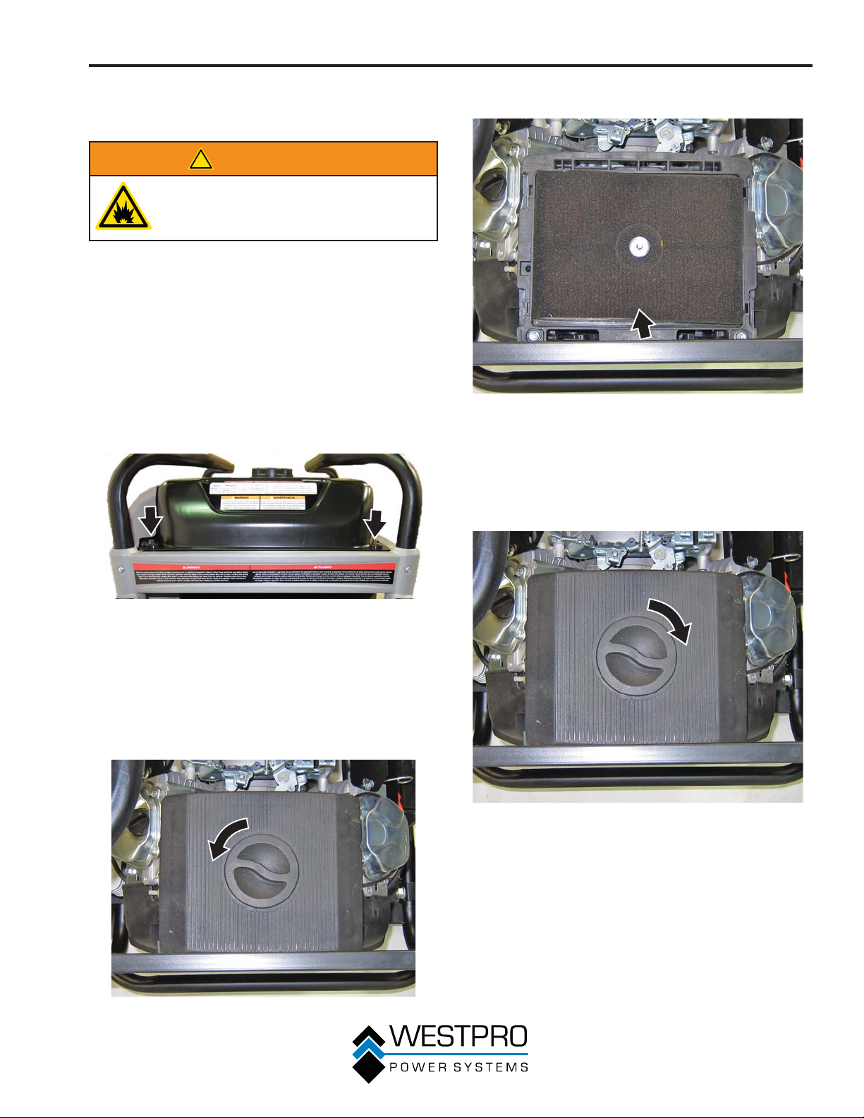
MANTENIMIENTO
MANTENIMIENTO DEL FILTRO
DE AIRE
!
ADVERTENCIA
Nunca use gasolina ni otros disolventes
inflamables para limpiar el filtro de aire.
Debe usar únicamente detergente para el
hogar para limpiar el filtro de aire.
Inspeccione y reemplace el filtro de aire
– 10KPRO
El filtro de aire debe inspeccionarse después de 50 horas de
uso o cada 3 meses (se debe aumentar la frecuencia si el
generador funciona en un entorno donde abunda el polvo).
1. Apague el generador y déjelo enfriar durante varios
minutos si está en funcionamiento.
2. Traslade el generador hasta una superficie plana y
nivelada.
3. Extraiga los 4 tornillos de montaje de la parte superior
del depósito de combustible (vea la Figura 42).
5. Retire el elemento del filtro de aire (vea la Figura 44).
Figura 44 – Elemento de filtro de aire
(Parte N° 160059)
6. Inserte el elemento del filtro de aire para la suciedad, el
polvo y los residuos. No lave el elemento. Si el elemento
del filtro de aire está sucio, reemplace el filtro.
7. Instale el elemento del filtro de aire y coloque la cubierta
y la perilla (vea la Figura 45).
Figura 42 – Tornillos del depósito de combustible
OTA:N Para la fotografía se retira el depósito de
combustible. El filtro de aire puede recibir
servicios de mantenimiento sin extraer el
depósito de combustible.
4. Eleve el depósito de combustible levemente y desatornille
la perilla de la cubierta del filtro de aire y retire la cubierta
(vea la Figura 43).
Figura 43 – Cubierta y perilla del filtro de aire
Figura 45 – Instalación de la cubierta del filtro de aire
8. Instale los 4 tornillos del depósito de combustible.
39
Page 92
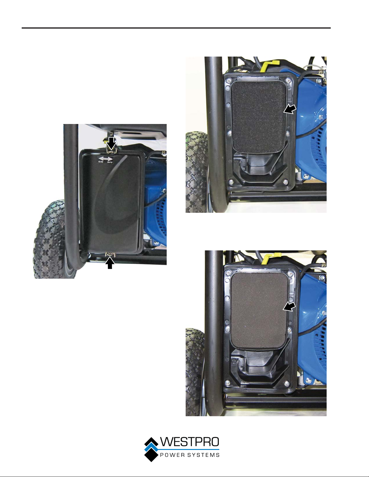
MANTENIMIENTO
Limpieza del filtro de aire – 8KPRO
Se debe limpiar el filtro de aire cada 50 horas de uso o cada
3 meses (se debe aumentar la frecuencia si el generador
funciona en un entorno donde abunda el polvo).
1. Apague el generador y déjelo enfriar durante varios
minutos si está en funcionamiento.
2. Traslade el generador hasta una superficie plana y
nivelada.
3. Desabroche los broches de la parte superior e inferior
de la tapa del filtro de aire (vea la Figura 46) y extraiga la
tapa del filtro de aire.
4. Extraiga el filtro de aire exterior negro para partículas
gruesas (vea la Figura 47).
Figura 46 – Procedimiento para extraer la tapa del filtro de
aire
Figura 47 – Procedimiento para extraer el filtro de aire exterior
para partículas gruesas
5. Extraiga el filtro de aire interior gris para partículas finas
(vea la Figura 48).
40
Figura 48 – Procedimiento para extraer el filtro de aire interior
para partículas finas
Page 93
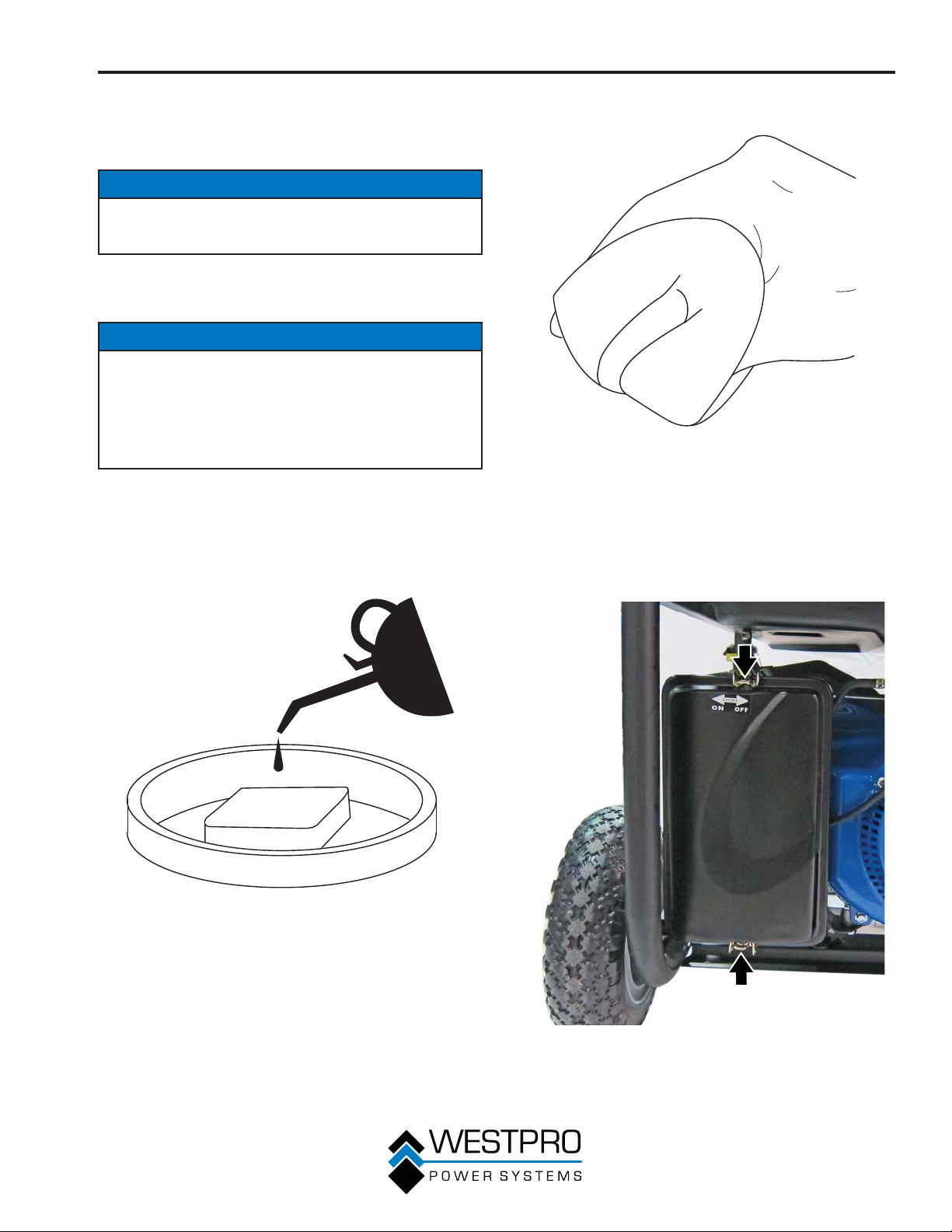
MANTENIMIENTO
6. Lave los elementos de espuma del filtro de aire
sumergiéndolos en una solución de detergente para el
hogar y agua caliente. Apriete lentamente la espuma
hasta que quede completamente limpia.
AVISO
NUNCA tuerza o rasgue el elemento de espuma del filtro
de aire durante la limpieza o el secado. Sólo debe apretarlo
lenta pero firmemente.
7. Enjuáguelo en agua limpia sumergiendo los elementos
del filtro de aire en agua dulce y apretándolos
lentamente.
AVISO
Nunca deseche la solución jabonosa usada para limpiar
el filtro de aire arrojándola en un desagüe, en la tierra o
en aguas subterráneas o vías fluviales. Siempre debe ser
responsable con el medio ambiente. Siga los lineamientos
de la EPA o de otras agencias gubernamentales para el
desecho adecuado de materiales peligrosos. Consulte a las
autoridades locales o las instalaciones de reciclado.
8. Deseche la solución jabonosa usada de manera
adecuada.
9. Seque los elementos del filtro de aire apretándolos
lentamente con firmeza otra vez.
10. Una vez que los filtros de aire estén secos, recúbralos
con aceite para motor limpio (vea la Figura 49).
11. Se deben apretar los filtros para eliminar el aceite
excedente (vea la Figura 50).
Figura 50
12. Primero, coloque el filtro de aire interior gris para
partículas finas en el alojamiento del filtro de aire.
13. Coloque el filtro de aire exterior negro para partículas
gruesas sobre el fino para partículas finas.
14. Coloque la tapa del filtro de aire abrochando los broches
de la parte superior e inferior del conjunto del filtro de
aire (vea la Figura 51).
Figura 49
Figura 51 – Colocación de la tapa del filtro de aire
41
Page 94
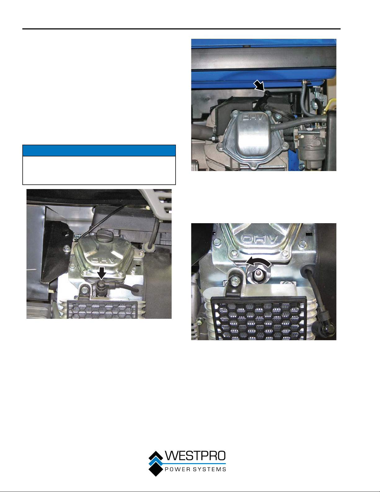
MANTENIMIENTO
MANTENIMIENTO DE LA
BUJÍA DE ENCENDIDO
Se debe controlar y limpiar la bujía de encendido cada 100
horas de uso o 6 meses y se la debe reemplazar después de
300 horas de uso o todos los años.
1. Detenga el generador y deje que se enfríe durante varios
minutos si está en funcionamiento.
2. Traslade el generador hasta una superficie plana y
nivelada.
3. Retire el capuchón de la bujía de encendido tirando
firmemente de la manija plástica de dicho capuchón,
alejándolo directamente del motor (vea la Figura 52 y la
Figura 53).
AVISO
Nunca debe aplicar una carga lateral ni mover la bujía
hacia los costados cuando extraiga la bujía. Si se aplica
una carga lateral o se mueve la bujía hacia los costados se
puede agrietar y se puede dañar el capuchón de la bujía.
Figura 53 – Extracción del capuchón de la bujía de encendido
– 8KPRO
4. Limpie la zona que rodea a la bujía de encendido.
5. Con la llave de cubo de 13/16" para bujías de encendido
suministrada, retire la bujía de la cabeza del cilindro (vea
la Figura 54 y la Figura 55).
Figura 52 – Extracción del capuchón de la bujía de encendido
– 10KPRO
42
Figura 54 – Extracción de la bujía de encendido – 10KPRO
Page 95
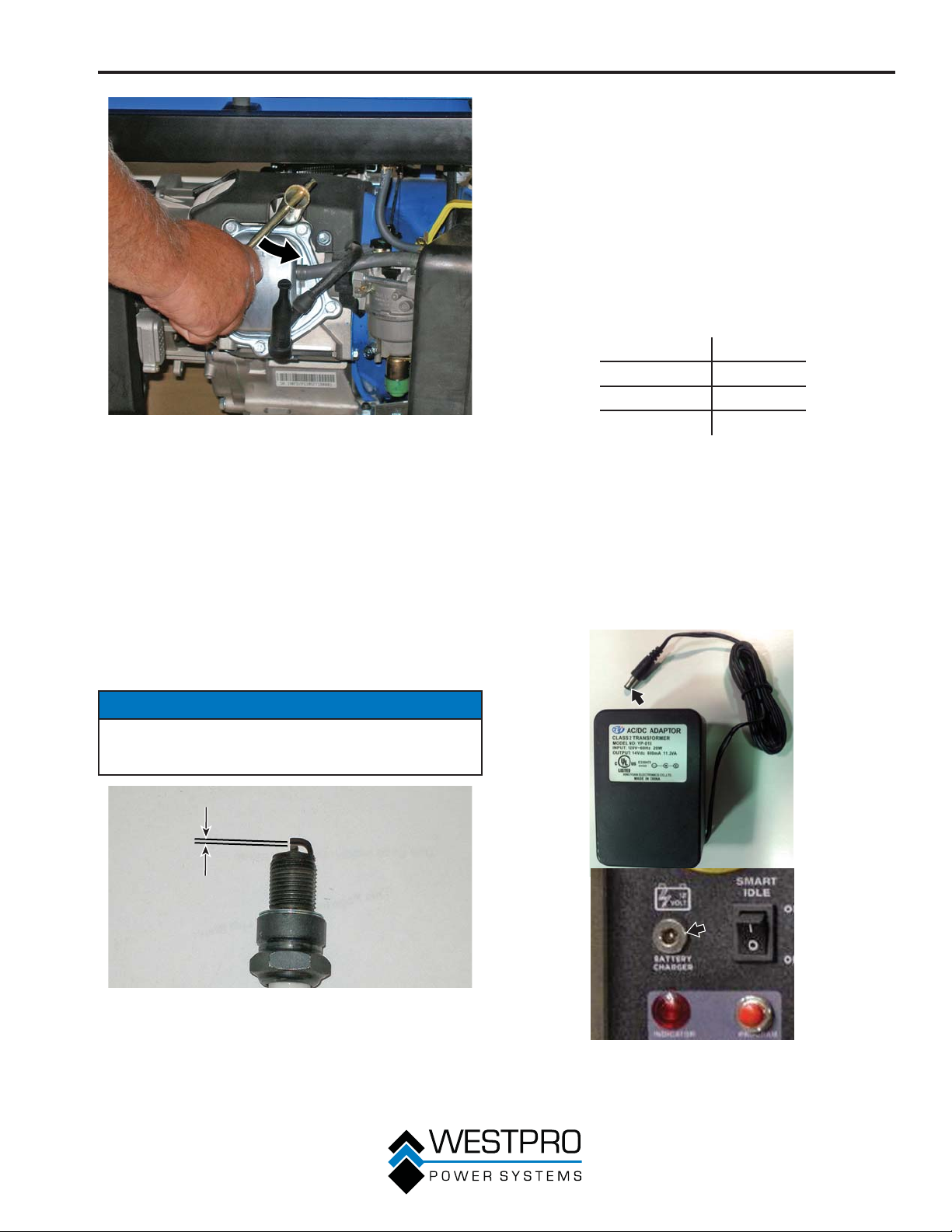
Figura 55 – Extracción de la bujía de encendido – 8KPRO
MANTENIMIENTO
8. Coloque la bujía de encendido siguiendo atentamente los
pasos que se detallan a continuación:
a - Inserte con cuidado la bujía nuevamente dentro de
la cabeza del cilindro. Enrosque manualmente la
bujía hasta que sobresalga la base.
b - Con la llave de cubo de 13/16" para bujías
suministrada, gire la bujía hasta asegurar que esté
completamente asentada.
c - Vuelva a colocar el capuchón de la bujía,
comprobando que se enganche completamente con
la punta de la bujía.
Reemplazo recomendado de la bujía:
AutoLite 63
Champion RN9YC
Bosch WR7DS
Torch F6RTC
6. Coloque una tela limpia sobre la abertura que se generó
al extraer la bujía de encendido para asegurar que no
pueda ingresar suciedad en la cámara de combustión.
7. Inspeccione la bujía de encendido para detectar:
x Si el aislador está agrietado o astillado
x Si está excesivamente desgastada
x La separación de la bujía de encendido (el límite que
se acepta es de 0,024 – 0,032 pulgadas [0,60 – 0,80
mm]) (vea la Figura 56).
Si la bujía de encendido tiene algún problema en relación
con las condiciones establecidas precedentemente, debe
reemplazarla por una Champion RN9YC o equivalente.
AVISO
Sólo debe usar la bujía de encendido recomendada
(Champion RN9YC o equivalente). Si se utiliza una bujía de
encendido no recomendada se podría dañar el motor.
MANTENIMIENTO DE LA
BATERÍA
Para garantizar que la batería se mantenga cargada, el
generador debe arrancarse cada 2 a 3 meses y ejecutarse
por un mínimo de 15 minutos o el cargador debe enchufarse
al generador y el generador debe cargarse durante la
noche. Enchufe el cable del cargador al puerto de carga del
generador. Enchufe el cargador a un tomacorrientes de CA de
110/120 voltios (vea la Figura 57).
Figura 56 – Requisitos de separación de la bujía
Figura 57 – Cargador CA de 120 voltios
43
Page 96
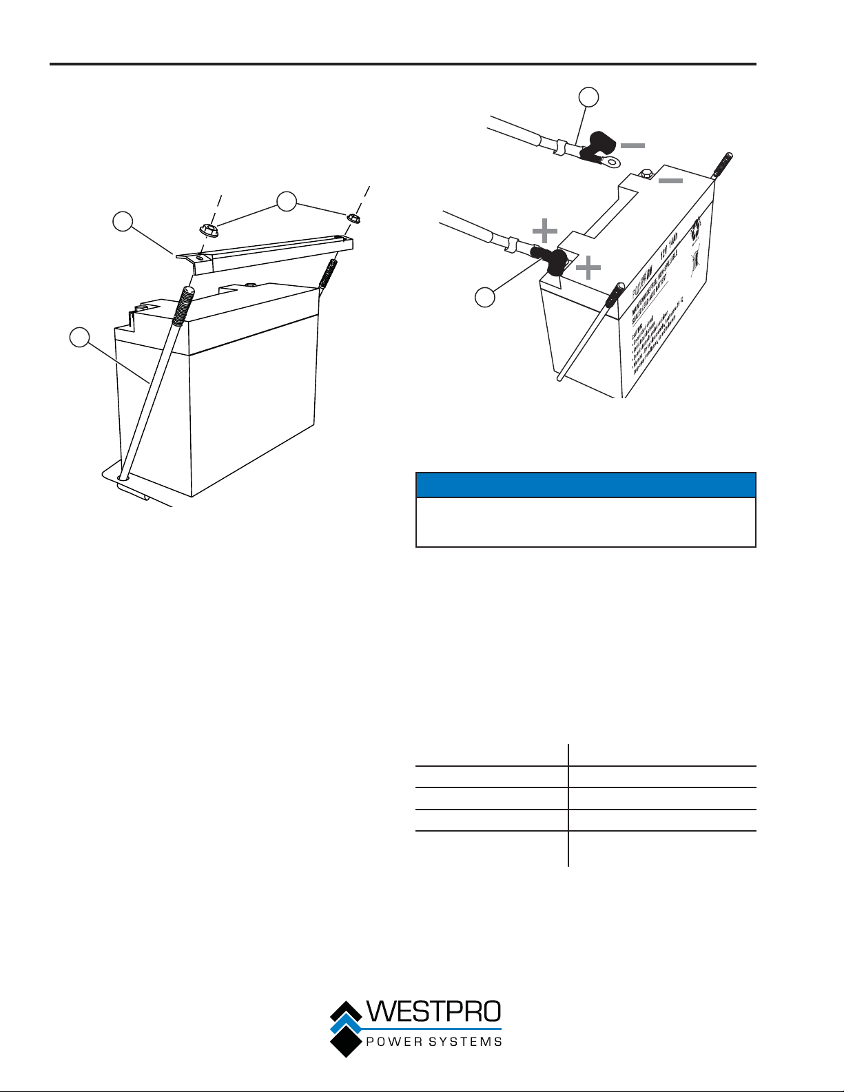
MANTENIMIENTO
Reemplazo de la batería
1. Extraiga el cable de la bujía de encendido.
2. Suelte y quite las tuercas de la placa de sujeción de la
batería y retire la placa de las barras soporte (vea la
Figura 58).
1
2
3
Figura 58
1 - Tuercas
2 - Placa de sujeción
de la batería
3. Incline la batería levemente hacia adelante para acceder
a los cables de la batería.
4. Desconecte el cable negativo (-) negro de la batería
primero.
5. Desconecte el cable positivo (+) rojo en segundo lugar y
extraiga la batería.
3 - Barras soporte
2
1
Figura 59
1 - Cable positivo (+)
rojo de la batería
2 - Cable negativo
(-) negro de la
batería
AVISO
Arroje a los residuos la batería usada de manera adecuada
según las pautas establecidas por su gobierno local o
estatal.
6. Instale la batería nueva en el bastidor del generador.
7. Conecte el cable positivo (+) rojo primero a la batería.
8. Conecte el cable negativo (-) negro a la batería en
segundo lugar.
9. Instale la placa de sujeción de la batería con las tuercas
que quitó en el paso 2.
10. Instale el cable de la bujía de encendido a la bujía de
encendido.
44
La batería para el 10KPRO, N.° de pieza 100170, es la misma
que la de la silla de ruedas.
Tipo Sellada de plomo ácido
Modelo LA-12V20-NB
Voltios 12
Amperios 21
Dimensiones
(L x H x A)
7,13 x 3 x 6,63 pulgadas
(18,1 x 7,6 x 16,8 cm)
Page 97
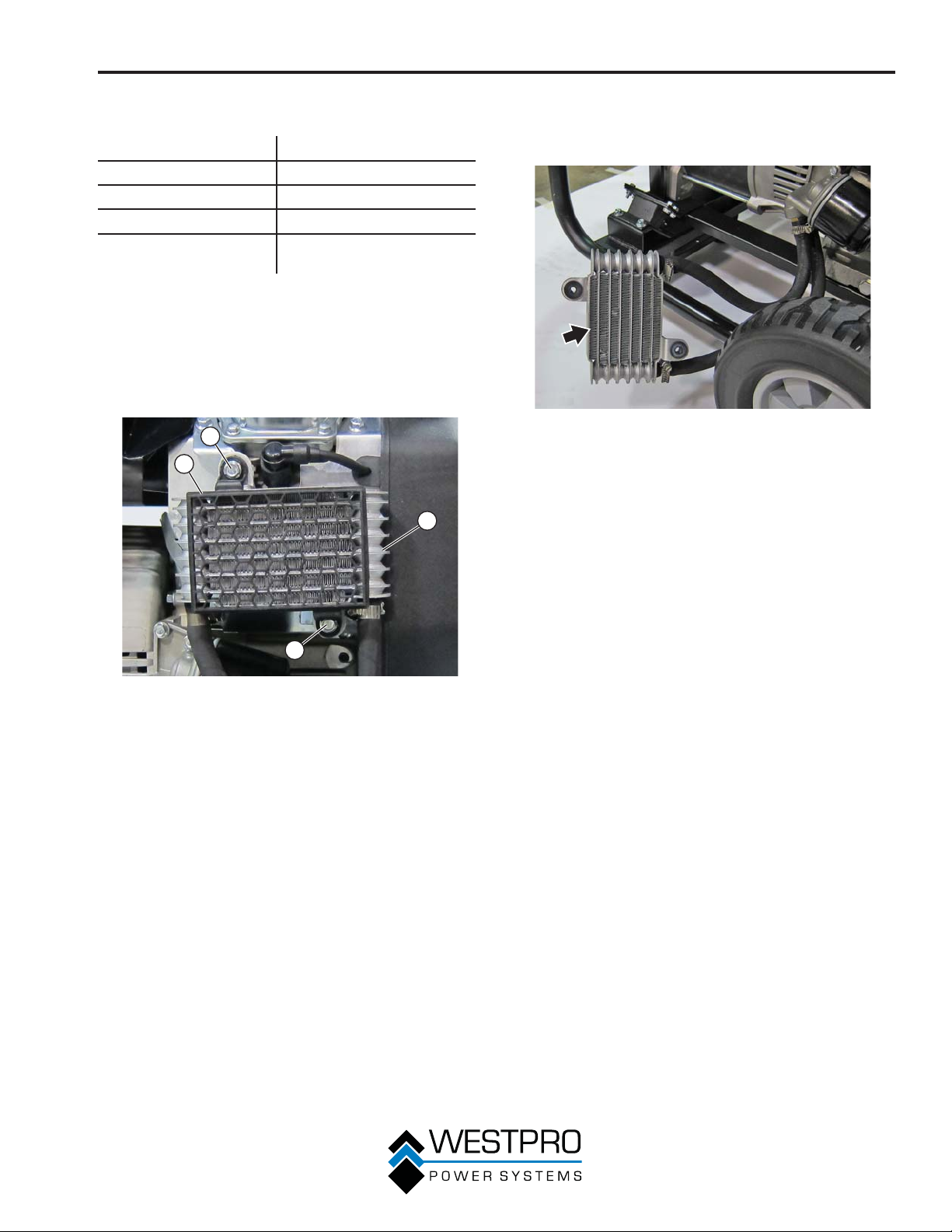
MANTENIMIENTO
La batería para el 8KPRO, N.° de pieza 100024, es la misma
que para una motocicleta/la red.
Tipo 14L-A2
Modelo CYLA214SXTA
Voltios 12
Amperios 14
Dimensiones
(L x H x A)
5,9 x 4,33 x 3,43 pulgada
(15,0 x 11,0 x 8,7 cm)
LIMPIEZA DEL ENFRIADOR
DE ACEITE DEL MOTOR –
10KPRO
1. Extraiga los tornillos del enfriador de aceite (vea la Figura
60).
1
2
3
3. Inspeccione las aletas del enfriador de aceite para
detectar suciedad y residuos. Limpie las aletas usando
aire comprimido que no supere los 30 psi (207 kPa) (vea
la Figura 61).
Figura 61 – Aletas del enfriador de aceite
4. Use tornillos para instalar el enfriador de aceite y la
protección.
1
Figura 60 – Enfriador de aceite del motor
1 - Tornillos del
enfriador de aceite
2 - Protección del
enfriador de aceite
2. Quite la protección del enfriador de aceite y el enfriador
de aceite.
3 - Enfriador de aceite
45
Page 98
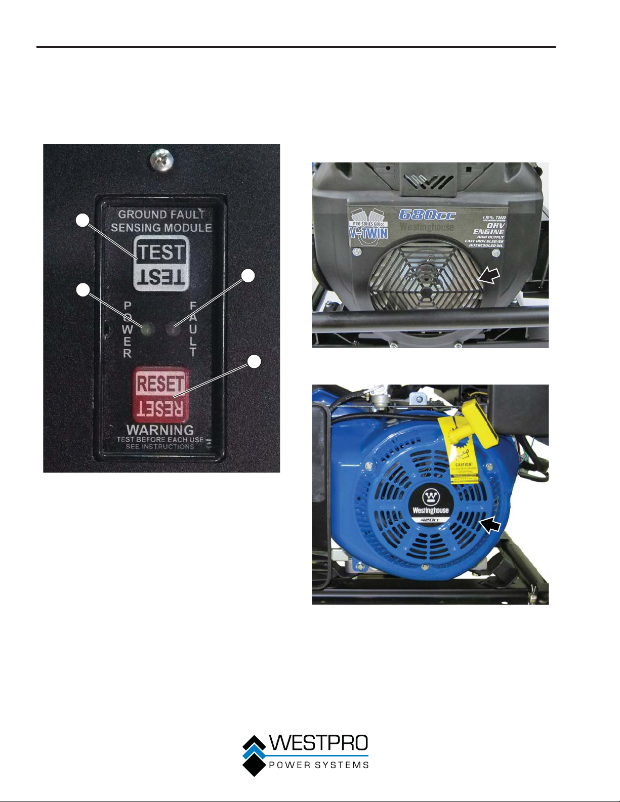
MANTENIMIENTO
PROBAR EL SENSOR DE
FALLA A TIERRA
1. Arranque el generador y deje que se caliente.
2. Presione el botón de prueba en el sensor de falla a tierra
(vea la Figura 62).
1
3
4
2
LIMPIEZA DEL GENERADOR
Es importante inspeccionar y limpiar el generador antes de
cada uso.
Limpie todos los orificios de entrada y salida de aire del
motor – Asegúrese de que todos estos orificios de entrada
y salida de aire del motor estén limpios y no haya suciedad
ni residuos a fin de garantizar que el motor no funcione en
caliente (
Figura 63 – Orificios de entrada y salida de aire del motor –
vea la Figura 63 y la Figura 64).
10KPRO
Figura 62 – Prueba del sensor de falla a tierra
1 - Botón de prueba
2 - Botón para
reiniciar
3. La luz junto a "fault" (falla) se encenderá y el disyuntor
principal saltará.
4. Si el disyuntor principal no salta, el sensor de falla a
tierra no funciona correctamente y debe repararse antes
de que pueda operarse el generador.
5. Presione el botón para reiniciar y vuelva a iniciar el
disyuntor principal. La luz junto a "fault" (falla) se apagará
y debería encenderse la luz junto a "power" (suministro).
Se restablecerá el suministro eléctrico a todos los
tomacorrientes.
46
3 - Luz de falla
4 - Luz de energía
Figura 64 – Orificios de entrada y salida de aire del motor –
8KPRO
Page 99
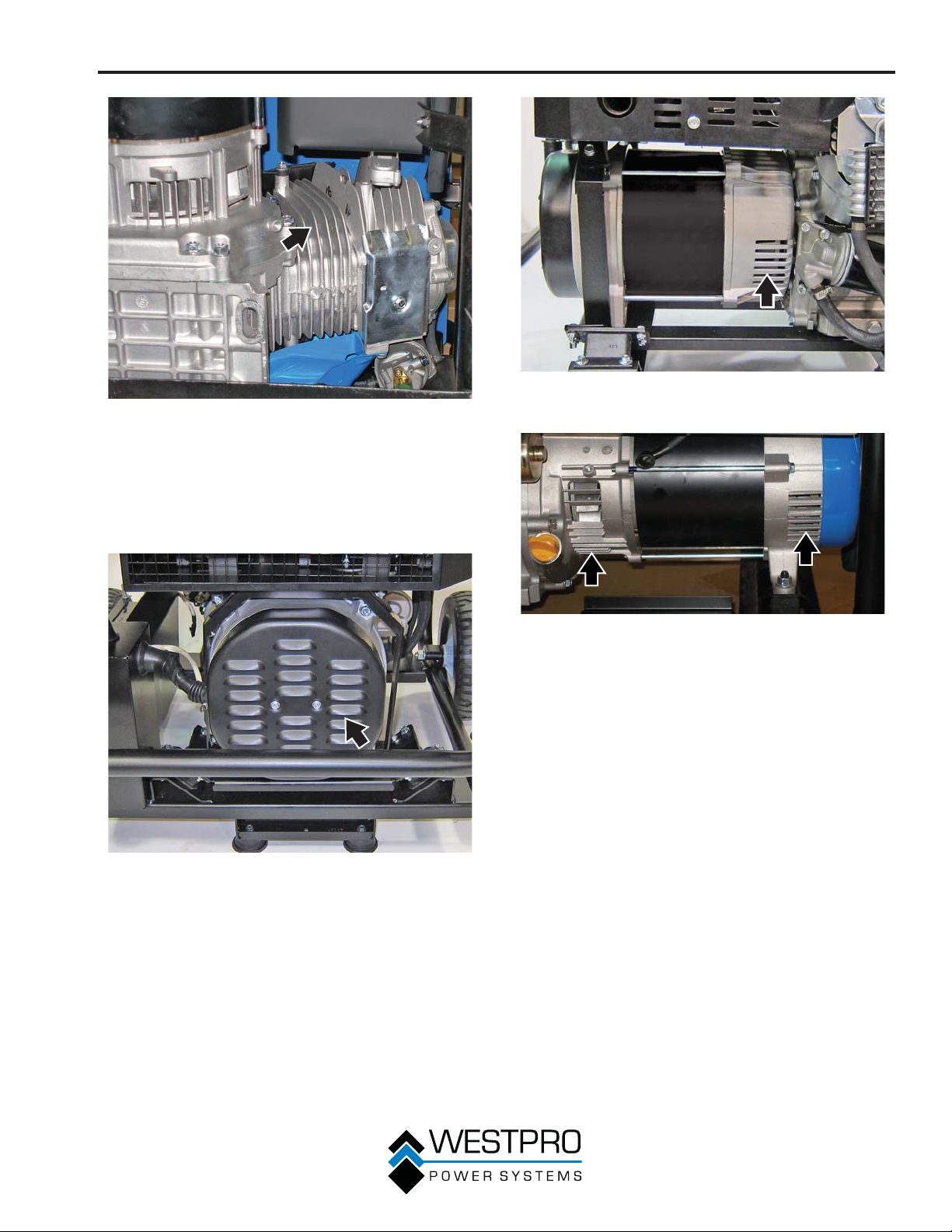
MANTENIMIENTO
Figura 65 – Aletas de enfriamiento del motor – 8KPRO
Limpie todas las entradas de aire de refrigeración y todos
los orificios de escape del alternador – Compruebe que las
entradas de aire de refrigeración y los orificios de escape del
alternador estén libres de desechos y obstrucciones. Use una
aspiradora para quitar suciedad y residuos atrapados en las
entradas de aire de refrigeración y orificios de escape (vea la
Figura 66, la Figura 67 y la Figura 68).
Figura 67 – Entrada y salida de aire de enfriamiento del
alternador Orificio – 10KPRO
Figura 68 – Entrada y salida de aire de enfriamiento del
alternador Orificio – 8KPRO
Limpieza general del generador – Utilice una tela húmeda
para limpiar todas las superficies restantes.
Figura 66 – Entrada de aire de refrigeración y orifico de
47
escape del alternador
Page 100
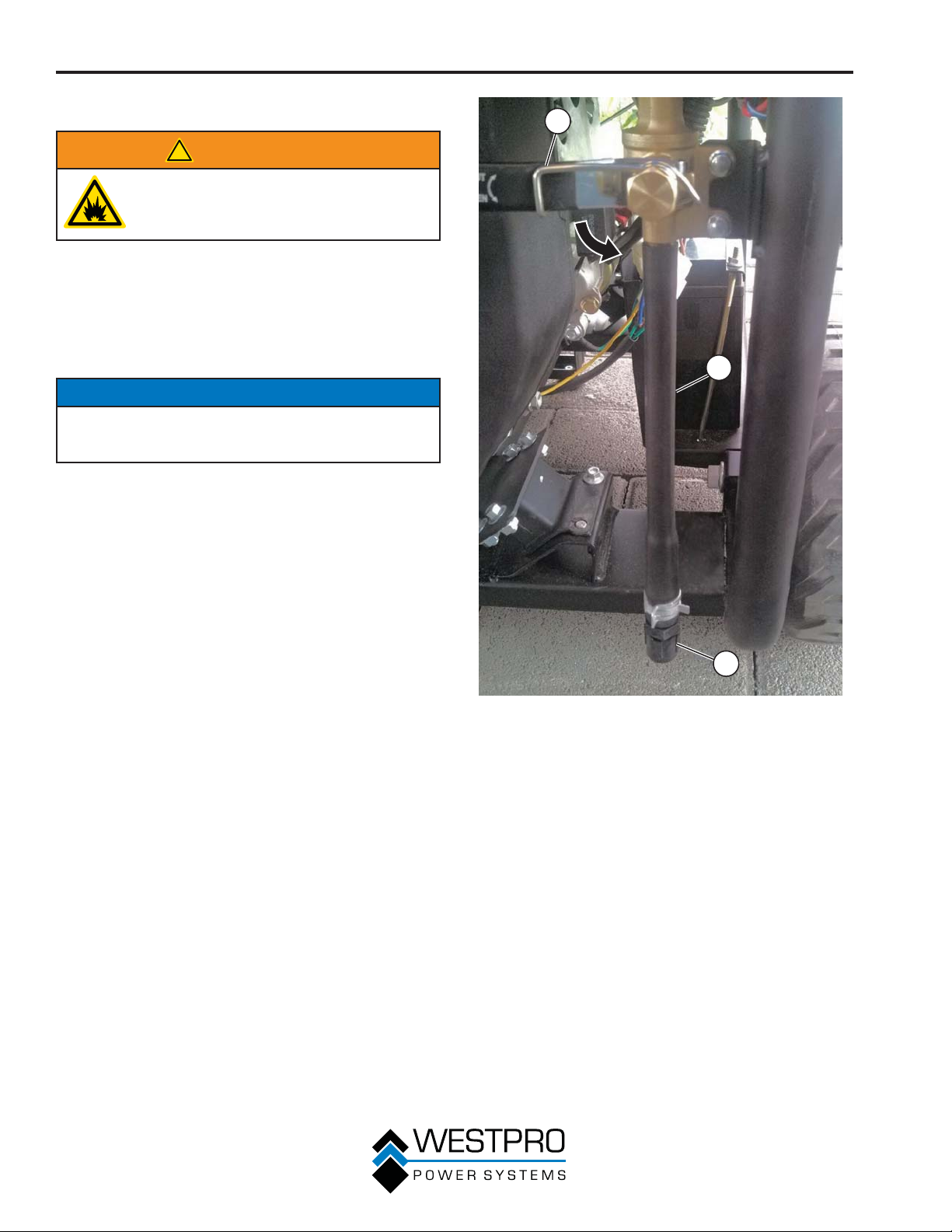
MANTENIMIENTO
DRENAJE RÁPIDO
!
ADVERTENCIA
La gasolina y los vapores de la gasolina
son extremadamente inflamables y
explosivos en determinadas condiciones.
Limpie todos los derrames de inmediato.
El generador cuenta con una función de drenaje rápido. Esta
función evitará los efectos dañinos de los combustibles de
etanol de fases separadas. Durante el invierno, el alcohol y
el agua pueden separarse de la gasolina en combustibles
mezclados. Dado que el agua y el alcohol son más pesados
que la gasolina, estos líquidos corrosivos descenderán al
fondo del depósito de combustible.
AVISO
Nunca elimine los materiales peligrosos de manera
irresponsable, arrojándolos en una alcantarilla, al suelo, en
aguas subterráneas o en vías fluviales.
1. Retire la tapa de la manguera de drenaje del extremo de
la manguera de drenaje.
2. Abra la válvula de drenaje rápido (vea la Figura 69) y
drene el combustible a un recipiente adecuado.
1
2
3
Figura 69 – Válvula de drenaje rápido
1 - Válvula de
drenaje rápido
2 - Manguera de
drenaje
3. El agua y el alcohol serán transparentes o turbios en el
combustible. Continúe drenando hasta que se observe
que sale combustible limpio de la manguera de drenaje.
4. Cierre la válvula de drenaje rápido e instale la tapa de la
manguera de drenaje.
5. Elimine el combustible recolectado de la forma adecuada.
6. El procedimiento de drenaje rápido también puede
utilizarse para transferir combustible desde el generador
para usar en otros productos de motor de gasolina.
3 - Tapa de la
manguera de
drenaje
48
 Loading...