

Page 1

Owner’s Manual
Indoor Lighting Fixture
Installation Instructions
W-186
021605
Please write model number here for future reference: / Veuillez noter le numéro de modèle aux fins de référence ultérieure: / Por favor, incluya el número del modelo aquí para
futura referencia:
Page 2

ASSEMBLY INSTRUCTIONS FOR INDOOR LIGHT FIXTURE
Congratulations on yourWestinghouse purchase. This fixture has been designed to give you
many years of beauty and service. Please email questions and comments to:
catalogroom@westinghouselighting.com.
NOTE: Carefully unpack fixture and parts. Make sure all parts are included before
discarding any packing materials (see figure 1).
WARRANTY INFORMATION
This Westinghouse Lighting Fixture is warranted against defects in material and workmanship for
a period of Five Years from purchase date. This warranty is in lieu of all other
warranties expressed or implied.
This warranty does not cover acts of nature such as lightning damage, or corrosion and
discoloration of components, nor does it cover damages caused through abuse, improper
installation, surges in electric current, or acts of third parties.
This warranty does not cover broken glass. If fixture is received with broken glass, please call
Westinghouse Lighting for free replacement.
This warranty does not cover costs of removing and re-installing the light fixture.
If this fixture fails for any reason covered by this warranty, simply return the fixture with a copy of
the original sales receipt, freight prepaid and Westinghouse Lighting, at its option, shall repair or
replace the fixture or refund the purchase price.
WARNING ELECTRICAL SHOCK CAN RESULT IN SERIOUS INJURY.
Read and follow instructions exactly as shown. If instructions are unclear,
do not proceed. Contact a qualified electrician. Read all instructions
before beginning. Proper wiring is essential for safe operation of this fixture. When cutting or drilling into walls or ceilings, do not damage electrical wiring, gas lines, or water lines. If any of the fixture or wiring components are damaged, do not install fixture. Return to place of purchase.
For fixtures provided with 75° C or 90° C supply wire warning only. (These
warnings are provided on the U.L. label and on the fixture carton.) Risk of
fire. Most dwellings built before 1985 have supply wires rated 60° C.
Consult a qualified electrician before installing.
NOTE: For fixture employing a grounded convenience outlet. This fixture
employs a grounded type receptacle and is not intended for connection to
a two wire ungrounded source of supply.
Applicable only to portable lamps:
To reduce the risk of electrical shock, all portable lamps have a polarized
plug (one blade is wider than the other). This plug will fit into a polarized
outlet only one way. If plug does not fit, reverse the plug. If it still does not
fit, contact a qualified electrician. Never use with an extension cord unless
plug can be fully plugged into the extension cord. Do not alter the plug.
2
Page 3
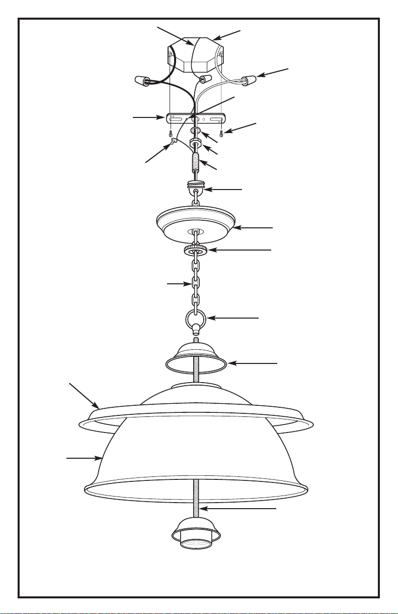
FIGURE 1.
GROUND
WIRE
*OUTLET
BOX (B)
SIDE HOLE (Q)
WIRE
CONNECTORS (O)
DECORATIVE
TRIM RING (G)
MOUNTING
BAR (A)
GREEN
GROUNDING
SCREW (P)
CHAIN (L)
*OUTLET BOX
SCREWS (C)
LOCK WASHER (F)
HEX NUT (D)
MOUNTING NIPPLE (E)
SCREW
COLLAR (N)
CANOPY 2 (I2)
SCREW COLLAR
RING (M)
FIXTURE LOOP (J)
CANOPY 1 (I1)
GLASS
SHADE (H)
Line art shown may not exactly match the fixture enclosed.
However, the installation instructions do apply to this fixture.
3
NIPPLE (K)
*NOT SUPPLIED
Page 4

MOUNTING AND WIRING INSTRUCTIONS
NOTE: Underwriters Laboratories (UL) does not require all fixtures to have ground wires. These
fixtures meet all UL specifications.
1. Turn off power at circuit box to avoid possible electric shock.
2. Secure mounting bar (A) to outlet box (B) with outlet box screws (C) (not included) (see fig. 1).
3. Thread hex nut (D) onto mounting nipple (E) approximately 1/4 inch and insert lock washer
(F), then thread mounting nipple (E) into mounting bar (A) and secure hex nut (D).
4. Place decorative trim ring (G) over glass shade (H) (if applicable).
5. Thread fixture wires up through glass shade (H).
6. Slide canopy 1 (I1) and fixture loop (J) (in order) down over fixture wires and then secure
fixture loop (J) to nipple (K).
7. Open one link on bottom end of chain (L). Attach to fixture loop (J). Securely close link on
chain (L).
8. Thread screw collar ring (M) onto screw collar (N), then place canopy 2 (I2) over top of
screw collar (N).
9. Lace wires up through every other link on chain (L) then through screw collar (N) and
mounting nipple (E).
10. Open one link on top end of chain (L). Attach to loop on screw collar (N). Securely close
link on chain (L).
11. Identify color coding of fixture wires (see fig. 2).
12. To connect wires, take black fixture wire (group A from fig. 2) and place evenly against
black outlet box wire. Do not twist wires.
13. Fit wire connector (O from fig. 1) over wires and twist until there is a firm connection. If
wire connector (O) easily comes off, reattach and check again for a firm connection.
14. Repeat steps 12 and 13 with the white (group B from fig. 2) fixture wires and outlet box wires.
15. Partially thread green grounding screw (P) into side hole (Q) on mounting bar (A) (see fig. 1).
16. Wrap ground wire from fixture around green grounding screw (P) leaving enough excess
wire to then connect ground wire and outlet box wire with wire connector (O), if applicable.
17. Tighten green grounding screw (P). Do not over tighten.
18. Remove screw collar ring (M) from screw collar (N) and secure screw collar (N) to mounting
nipple (E).
19. Tuck wires inside outlet box (B).
20. Raise canopy 1 (I1) to ceiling and secure screw collar ring (M) to screw collar (N).
FIXTURE ASSEMBLY INSTRUCTIONS
Warning: This fixture is for indoor use only.
1. Install lamp(s). Do not exceed recommended wattage.
2. Turn power back on at circuit box.
4
Page 5

LES INSTRUCTIONS D'ASSEMBLAGE DE L'APPAREIL
D'ÉCLAIRAGE POUR UTILISATION INTÉRIEURE
Félicitations ! Vous avez acheté un produit de Westinghouse Lighting. Cet appareil d'éclairage a
été conçu pour durer de nombreuses années. Veuillez envoyer vos questions et commentaires par
courriel, à l'adresse suivante : catalogroom@westinghouselighting.com
NNOOTTAA ::
pièces y sont avant de mettre l’emballage au rebut (voir fig. 1).
Déballez soigneusement l'appareil d'éclairage et les pièces. Assurez-vous que toutes les
GARANTIE LIMITÉE DE CINQ ANS
Cet appareil d'éclairage Westinghouse est assorti d’une garantie de 5 ans contre les défauts de
matériaux et de fabrication, qui entre en vigueur à partir de la date d'achat. La présente garantie
se substitue à toute autre garantie expresse ou tacite.
Cette garantie ne porte ni sur les dommages survenant suite à une catastrophe naturelle (telle que
la foudre), ni sur la corrosion ou la décoloration des pièces; la garantie ne porte pas sur les dommages survenant suite à une utilisation anormale, une installation impropre, une surtension de
courant électrique ou des actes d’un tiers.
Cette garantie ne porte pas sur le verre brisé. Si vous avez reçu votre appareil d'éclairage avec un
globe de verre brisé, veuillez appeler Westinghouse Lighting afin d’obtenir une pièce de remplacement sans frais.
Cette garantie ne porte pas sur les frais de démontage et de réinstallation du ventilateur.
Si cet appareil d'éclairage ne fonctionne pas pour une des raisons couvertes par la présente
garantie, renvoyez tout simplement l'appareil d'éclairage et une copie de la preuve d’achat originale, frais de transport prépayés, à Westinghouse Lighting qui, à sa discrétion, réparera ou remplacera l'appareil ou vous remboursera le montant du prix d’achat.
L'ÉLECTROCUTION POURRAIT CAUSER DE GRAVES BLESSURES PERSONNELLES.
Lisez ces instructions et suivez-les exactement comme illustré. En cas de
doute, ne commencez pas l'installation. Consultez un électricien qualifié. Lisez
toutes les instructions avant de commencer l'installation. Un câblage approprié
est essentiel au bon fonctionnement de cet appareil d’éclairage. Lorsque vous
faites une entaille ou que vous percez un trou dans un mur ou un plafond, n'endommagez pas les câbles électriques, les canalisations de gaz ou d'eau. Si l'un
des composants de raccordement ou de l'appareil d'éclairage est endommagé,
n'installez pas cet appareil d'éclairage. Retournez-le à l'endroit où vous l'avez
acheté.
Convient uniquement aux appareils comportant un avertissement indiquant que
l'appareil d'éclairage est doté d'un fil supportant une chaleur de 75°C ou 90°C.
(Ces avertissements se trouvent sur l'étiquette U.L. et sur l'emballage de l'appareil d'éclairage.)
NOTA: Pour appareil d’éclairage avec sortie terre. Cet appareil d’éclairage
utilise un réceptacle muni d’un fil de terre et ne doit pas être branché à un bloc
d’alimentation à deux fils non mis à la terre.
Ne s’applique qu’aux lampes portatives. Afin de réduire les risques d’incendie,
toutes les lampes portatives sont pourvues d’une fiche polarisée (une des
broches est plus large que l’autre). La fiche ne peut être branchée dans une
prise polarisée que d'une seule manière. Si la fiche ne s’insère pas, tournez-la
dans l’autre sens. Si elle ne s’insère toujours pas, communiquez avec un électricien qualifié. N’utilisez jamais une rallonge électrique si la fiche ne peut être
complètement insérée dans la rallonge. N’essayez pas d’altérer la fiche.
MISE EN GARDE:
5
Page 6

FIGURE 1.
FIL DE MISE
ALATERRE
*BOITE DE SORTIE
DE COURANT (B)
CONNECTEURS
DE FIL (O)
TROU LATERAL (Q)
BARRE DE
FIXATION (A)
BAGUE DE FINITION
DECORATIVE (G)
VIS DE MISE
ALATERRE
(VERTE) (P)
CHAINE (L)
*VIS DE LA BOITE DE
SORTIE DE COURANT (C)
RONDELLE DE BLOCAGE (F)
L’ECROU HEXAGONAL (D)
MANCHON FILET DE FIXATION (E)
COLLIER
FILETE (N)
CHAPEAU 2 (I2)
LA BAGUE
DU COLLIER
FILETE (M)
LA BOUCLE DE L’APPAREIL
D’ECLAIRAGE (J)
CHAPEAU 1 (I1)
ABAT-JOUR
EN VERRE (H)
Il est possible que le dessin illustré ici ne soit pas la reproduction exacte
de l’appareil d’éclairage contenu dans la boîte.
Les instructions d’installation demeurent cependant valables.
6
MANCHON FILETE (K)
*NON FOURNI
Page 7

INSTRUCTIONS DE MONTAGE ET DE RACCORDEMENT
NOTA : Underwriters Laboratories (UL) n’exige pas que tous les appareils d’éclairage comportent
des fils de mise à la terre. Ces appareils satisfont cependant à toutes les spécifications UL.
1. Mettez l’interrupteur de la boîte de fusibles à « OFF » afin d’éviter le risque d’électrocution.
2. Attachez la barre de fixation (A) à la boîte de sortie de courant (B) à l'aide des vis de la
boîte de sortie de courant (C) (non fournies) (voir fig. 1).
3. Vissez l’écrou hexagonal (D) au manchon fileté de fixation (E) d’environ 6 mm (1/4 de po)
et insérez la rondelle de blocage (F). Ensuite, vissez le manchon fileté de fixation (E) à la
barre de fixation (A) et fixez en place à l’aide de l’écrou hexagonal (D).
4. Placez la bague de finition décorative (G) par-dessus l’abat-jour en verre (H) (s’il y a lieu).
5. Faites passer les fils de l’appareil d’éclairage par l’abat-jour en verre (H).
6. Faites glisser le chapeau 1 (I1) et la boucle de l’appareil d’éclairage (J) (dans cet ordre) vers
le bas sur les fils de l’appareil d’éclairage et attachez la boucle de l’appareil d’éclairage (J)
au manchon fileté (K).
7. Ouvrez un maillon à l’extrémité inférieure de la chaîne (L). Attachez à la boucle de
l'appareil d'éclairage (J). Fermez bien le maillon de la chaîne (L).
8. Vissez la bague du collier fileté (M) au collier fileté (N), et placez le chapeau 2 (I2) par
dessus le collier fileté (N).
9. Maillez les fils à chaque deux maillons de la chaîne (L) d’abord et faites-les passer par le
collier fileté (N) et le manchon fileté de fixation (E) ensuite.
10. Ouvrez un maillon à l’extrémité supérieure de la chaîne (L). Attachez-le à la boucle se
trouvant sur le collier fileté (N). Fermez bien le maillon de la chaîne (L).
11. Identifiez la couleur des fils de votre appareil d'éclairage (voir fig. 2).
12. Afin de brancher les fils, prenez le fil noir de l'appareil d'éclairage (groupe A, fig. 2) et
placez-le de façon égale sur le fil noir provenant de la boîte de sortie de courant. Ne
tournez pas les fils ensemble.
13. Insérez les fils dans le connecteur (O) (fig. 1) et tournez-le jusqu'à ce que vous sentiez une
résistance. Si le connecteur (O) se dégage facilement, attachez le connecteur de nouveau et
vérifiez encore une fois si la connexion est solide.
14. Répétez les étapes 12 et 13 avec le fil blanc (groupe B, fig. 2) de l'appareil d'éclairage et les
fils de la boîte de sortie de courant.
15. Vissez en partie la vis verte de mise à la terre (P) dans le trou latéral (Q) se trouvant sur la
barre de fixation (A) (voir fig. 1).
16. Enroulez le fil de mise à la terre de l’appareil d’éclairage autour de la vis de mise à la terre
(P) verte en laissant suffisamment de fil pour brancher le fil de mise à la terre et le fil de la
boîte de sortie de courant au connecteur (O) (s’il y a lieu).
17. Serrez la vis verte de mise à la terre (P). Ne serrez pas outre mesure.
18. Retirez la bague du collier fileté (M) du collier fileté (N) et fixez le collier fileté (N) au
manchon fileté de fixation (E).
19. Enfouissez les fils dans la boîte de sortie de courant (B).
20. Soulevez le chapeau 1 (I1) au plafond et vissez la bague du collier fileté (M) au collier fileté (N).
INSTRUCTIONS D’ASSEMBLAGE DE L'APPAREIL D'ÉCLAIRAGE
Mise en Garde: À utiliser à l’intérieur seulement.
1. Installez la (les) ampoule(s). Ne dépassez pas le wattage recommandé.
2. Remettez l’interrupteur de la boîte de fusibles à « ON ».
7
Page 8

INSTRUCCIONES DE MONTAJE PARA EL ARTEFACTO DE
ILUMINACIÓN PARA INTERIORES
Le felicitamos por comprar este producto de Westinghouse Lighting. Este producto ha sido diseñado para brindarle muchos años de belleza y servicio. Si tiene preguntas o comentarios, por favor
envíe un mensaje electrónico a: catalogroom@westinghouselighting.com
NNOOTTAA::
Extraiga cuidadosamente el artefacto y las piezas. Verifique que contenga todas las partes
requeridas (consulte la figura 1) antes de descartar los materiales de empaque.
GARANTÍA LIMITADA DE CINCO AÑOS
Este producto de Westinghouse Lighting está garantizado contra defectos de materiales
yfabricación por un período de cinco años a partir de la fecha de compra. Esta garantía reemplaza toda otra garantía expresa o implícita.
La presente garantía no cubre desperfectos originados como resultado de actos de la
naturaleza tales como daños producidos por un rayo, o por corrosión y decoloración de los componentes, así como tampoco cubre los desperfectos ocasionados por uso indebido,
instalación inadecuada, cambios de tensión, o intervención de terceros.
Esta garantía no cubre la rotura de piezas de vidrio. Si recibe el artefacto con alguna pieza de
vidrio rota, sírvase llamar a Westinghouse Lighting para que le envíen una pieza de repuesto
gratis.
Esta garantía no cubre los gastos de desmontaje y reinstalación del artefacto.
Si este artefacto sufre un desperfecto causado por cualquiera de las razones cubiertas por esta
garantía, simplemente envíe el artefacto con una copia del comprobante original de compra, franqueo prepago, y Westinghouse Lighting, a su criterio, reparará o reemplazará el artefacto o le reintegrará el precio de compra.
ADVERTENCIA: UNA DESCARGA ELÉCTRICA PODRÍA CAUSAR LESIONES.
Lea y siga las instrucciones exactamente como se indica. Si las instrucciones
no son claras, no proceda con la instalación. Consulte a un electricista certificado. Lea todas las instrucciones antes de comenzar. Para que este artefacto
funcione sin riesgos, es esencial realizar correctamente el cableado. Al cortar
o perforar una pared o el cielo raso, no dañe el cableado eléctrico, las instalaciones de gas o de agua. Si alguno de los componentes del artefacto o cableado está dañado, no instale el artefacto. Devuélvalo al lugar donde lo compró.
NOTA: Para artefactos con tomacorriente de tierra de conveniencia.
ADVERTENCIA: “Este artefacto emplea un tomacorriente de tierra y no se debe
conectar a un tomacorriente de dos cables que no tiene puesta a tierra.”
Sólo para artefactos provistos con advertencias sobre cables de alimentación
para 75º C o 90º C (estas advertencias aparecen en la etiqueta U.L. y en el
cartón de embalaje).
Peligro de incendio. La mayoría de las casas construidas antes de 1985 tienen
cables de alimentación clasificados para 60° C. Antes de la instalación, consulte a un electricista certificado.
Se aplica solamente a lámparas portátiles. Para reducir el riesgo de descarga
eléctrica, todas las lámparas portátiles tienen una clavija polarizada (una pata
es más ancha que la otra). La clavija entra sólo en una dirección en un tomacorriente polarizado. Si la clavija no entra en el tomacorriente, inviértala. Si
tampoco así entra, llame a un electricista certificado. Nunca use el artefacto
con un cordón de extensión si no puede insertar totalmente la clavija en el
cordón de extensión. No altere la clavija.
8
Page 9

FIGURA 1.
CABLE DE
TIERRA
BARRA DE
MONTAJE (A)
TORNILLO
VERDE DE
TIERRA (P)
CADENA (L)
*CAJA DE
EMBUTIR (B)
CONECTORES
DE ROSCA (O)
ORIFICIO LATERAL (Q)
*TORNILLOS CAJA
DE EMBUTIR (C)
ARANDELA DE PRESION (F)
TUERCA HEXAGONAL (D)
NIPLE DE MONTAJE (E)
COLLAR
ROSCADO (N)
DOSEL 2 (I2)
ENROSQUE EL
ANILLO DEL COLLAR
ROSCADO (M)
FIJELO AL ASA DEL
ARTEFACTO (J)
ANILLO
DECORATIVO (G)
PANTALLA
DE VIDRIO (H)
Los dibujos pueden no coincidir exactamente con el artefacto incluido.
Sin embargo, las instrucciones de instalación se aplican a este artefacto.
9
DOSEL 1 (I1)
NIPLE (K)
*NO INCLUIDO
Page 10

INSTRUCCIONES DE MONTAJE Y CABLEADO
NOTA: Underwriters Laboratories (U.L.) no requiere que todos los artefactos tengan cables de
tierra. Estos artefactos cumplen con todas las especificaciones U.L.
1. Desconecte el suministro eléctrico en la caja de fusibles para evitar la posibilidad de
descarga eléctrica.
2. Fije la barra de montaje (A) a la caja de embutir (B) con los tornillos correspondientes (C)
(no incluidos) (vea la Fig. 1).
3. Enrosque la tuerca hexagonal (D) en el niple de montaje (E) aproximadamente 6 mm (1/4
pulg.) e inserte la arandela de presión (F); luego enrosque el niple de montaje (E) en la
barra de montaje (A) y ajuste la tuerca hexagonal (D).
4. Coloque el anillo decorativo (G) sobre la pantalla de vidrio (H) (si corresponde).
5. Pase los cables del artefacto a través de la pantalla de vidrio (H).
6. Deslice hacia abajo el dosel 1 (I1) y el asa del artefacto (J) (en este orden) sobre los cables
del artefacto y luego asegure el asa del artefacto (J) al niple (K).
7. Abra un eslabón en el extremo inferior de la cadena (L). Fíjelo al asa del artefacto (J).
Cierre el eslabón de la cadena (L) asegurándolo.
8. Enrosque el anillo del collar roscado (M) al collar roscado (N), luego coloque el dosel 2 (I2)
sobre la parte superior del collar roscado (N).
9. Entreteja el cable pasándolo por uno de cada dos eslabones de la cadena (L); páselo luego a
través del collar roscado (N) y el niple de montaje (E).
10. Abra un eslabón en el extremo superior de la cadena (L). Fíjelo al asa del collar roscado
(N). Cierre el eslabón de la cadena (L) asegurándolo.
11. Identifique el color de los cables de su artefacto (vea la Fig. 2).
12. Para conectar los cables, tome el cable negro del artefacto (grupo A de la Fig. 2) y colóquelo
uniformemente contra el cable negro de la caja de embutir. No retuerza los cables.
13. Coloque un conector de rosca (O de la Fig. 1) sobre los cables y enrósquelo hasta que lo
sienta firme. Si el conector para cables (O) se desprende fácilmente, vuelva a ajustar el
conector y compruebe una vez más que la conexión esté firme.
14. Repita los pasos 12 y 13 para conectar los cables blancos del artefacto (grupo B de la Fig. 2)
y los de la caja de embutir.
15. Enrosque parcialmente el tornillo verde de tierra (P) en el orificio lateral (Q) de la barra de
montaje (A) (vea la Fig. 1).
16. Enrolle el cable de tierra del artefacto en el tornillo verde de tierra (P), dejando bastante
cable para conectar después el cable de tierra al cable de la caja de embutir con un
conector para cables (O), si corresponde.
17. Ajuste el tornillo verde de tierra (P). No lo apriete demasiado.
18. Quite el anillo del collar roscado (M) del collar roscado (N) y asegure el collar roscado (N) al
niple de montaje (E).
19. Introduzca los cables dentro de la caja de embutir (B).
20. Levante el dosel 1 (I1) hacia el cielo raso y asegure el anillo del collar roscado (M) al collar
roscado (N).
INSTRUCCIONES DE MONTAJE DEL ARTEFACTO
Advertencia: Este artefacto es para uso en interiores solamente.
1. Instale la(s) lámpara(s). No exceda el vataje recomendado.
2. Conecte nuevamente el suministro eléctrico en la caja de fusibles.
10
Page 11

GROUP A: GROUP B:
CONNECT TO BLACK
HOUSE WIRE
BLACK
WHITE OR GREY WITH TRACER
BROWN, GOLD OR BLACK
WITHOUT TRACER
BROWN, GOLD OR BLACK WITH TRACER
WHITE
WHITE OR GREY WITHOUT TRACER
CONNECT TO WHITE
HOUSE WIRE
NOTE: When parallel wire (SPT I & SPT II) is used; the neutral wire is square shaped
and ridged, and the hot wire will be round in shape and smooth. (See below.)
FIGURE 2.
GROUPE A: GROUPE B:
À BRANCHER AU FIL NOIR
DE LA R
ÉSIDENCE
NOIR
BLANC OU GRIS AVEC TRACEUR
BRUN, DOR
É OU NOIR SANS TRACEUR BRUN, DORÉ OU NOIR AVEC TRACEUR
BLANC
BLANC OU GRIS SANS TRACEUR
À BRANCHER AU FIL BLANC
DE LA R
ÉSIDENCE
NOTA: Dans le cas des fils parallèles (SPT I et SPT II), le fil neutre est carrè et Côtelè
et le fil chargè est rond et lisse. (Voir ci-dessus)
GRUPO A: GRUPO B:
CONÉCTELO AL CABLE
NEGRO DE LA CASA
NEGRO
BLANCO O GRIS CON MARCAS
MARR
ÓN, DORADO O NEGRO SIN MARCAS MARRÓN, DORADO O NEGRO CON MARCAS
BLANCO
BLANCO O GRIS SIN MARCAS
CON
ÉCTELO AL CABLE
BLANCO DE LA CASA
NOTA: Cuando se usa cable en paralelo (SPT 1 y SPT 2), el cable neutro es cuadrado
y acanalado, y el cable vivo es redondo y liso. (Ver abajo.)
FIGURE 2.
WARNING
Turn off electricity to the
mounting site before
beginning installation.
Mounting instructions
must be followed exactly
as shown for the fixture to
be safely supported.
MISE EN GARDE
Coupez le courant au site
de montage avant de
commencer l’installation.
Assurez-vous de suivre les
instructions de montage
exactement comme
illustré afin que l’appareil
d’éclairage soit installé de
façon sécuritaire.
FIGURA 2.
11
ADVERTENCIA:
Desconecte el suministro
eléctrico al sitio de montaje antes de comenzar la
instalación.
Se deben seguir las
instrucciones de montaje
exactamente como se
indican para que el
aparato tenga un soporte
seguro.
Page 12

CLEANING AND CARE
To clean, wipe fixture with soft cloth. Clean glass with mild soap. Spray from chemical cleaners can
discolor the finish of fixture. Extend-A-Finish Laquer Conditioner, Item#70295, is recommended once a
year to clean, condition, and protect fixture. Do not use scouring pads, powders, steel wool or abrasive
paper to clean this fixture.
NOTE FOR FIXTURES THAT ARE SOLID BRASS:
Your hand-crafted, solid brass lighting fixture has been coated with a durable, baked-on acrylic lacquer
which gives maximum protection against the weather. However, in time the brightness of the brass
will tarnish, giving way to an authentic old-world brass finish. To keep your solid brass fixture looking
new foryears to come, regularly apply a good quality, non-abrasive carwax to all metal surfaces, giving
the fixture an extra protective covering.
ORDERING PARTS
Keep this manual for future reference, and in case replacement parts are needed. Available parts can
be ordered from place of purchase. Use exact wording from diagrams when ordering parts.
NETTOYAGE ET ENTRETIEN
Pour nettoyer, essuyez l’appareil avec un linge doux. Nettoyez le verre à l’aide d’un savon doux. Les nettoyants chimiques risquent de décolorer le fini de l'appareil d'éclairage. L'utilisation de Extend-A-Finish
Lacquer Conditioner, article no 70295, est recommandée une fois par an pour nettoyer, traiter et protéger votre appareil d'éclairage. N'utilisez pas de tampons ou de poudre à récurer, de laine d'acier ou de
papier abrasif pour nettoyer cet appareil d'éclairage.
COMMANDE DE PIÈCES
Gardez ce manuel aux fins de référence ultérieure et au cas où vous auriez à commander des pièces de
remplacement. Les pièces disponibles peuvent être commandées à l'endroit où vous avez acheté votre
appareil d'éclairage. Si vous commandez des pièces, utilisez les termes figurant sur les diagrammes.
LIMPIEZA Y CUIDADO
Limpie el artefacto con un paño suave. Limpie el cristal con jabón suave. El rocío de productos
químicos de limpieza puede decolorar el acabado del artefacto. Se recomienda utilizar una vez al año
el acondicionador de laca de acabado prolongado, artículo No. 70295, para limpiar, acondicionar y proteger el artefacto. No use almohadillas o polvos para fregar, lana de acero o papel abrasivo para limpiar
este artefacto.
CÓMO SOLICITAR PARTES DE REPUESTO
Conserve este manual para futura referencia y para pedir partes de repuesto. Puede pedir todas las
partes de repuesto en el lugar donde compró el artefacto. Al solicitar partes, use exactamente los mismos términos que aparecen en la ilustración.
Westinghouse Lighting Corporation
Philadelphia, PA 19154-1099, U.S.A.
Westinghouse Lighting Corporation,
a Westinghouse Electric Corporation licensee
www.westinghouselighting.com
“Westinghouse” and “You can be sure...if it’s
Westinghouse” are registered trademarks of
Westinghouse Electric Corporation
© 2004 WESTINGHOUSE LIGHTING CORPORATION
12
 Loading...