

Westinghouse 60612, W-048 User Manual
Owner’s Manual
Indoor Lighting Fixture
Installation Instructions
W-048
060612
Please write model number here for future reference: / Veuillez noter le numéro de modèle aux fins de référence ultérieure: / Por favor, incluya el número del modelo aquí para
futura referencia:

2
ASSEMBLY INSTRUCTIONS FOR INDOOR LIGHT FIXTURE
Congratulations on yourWestinghouse purchase. This fixture has been designed to give you many
years ofbeautyand service. For questions and comments, please visit www.westinghouselighting.
com/contact-us.
NOTE: Carefully unpack fixture and parts. Make sure all parts are included before
discarding any packing materials (see figure 1).
WARRANTY INFORMATION
This Westinghouse Lighting Fixture is warranted against defects in material and workmanship for
a period of Five Years from purchase date. This warranty is in lieu of all other
warranties expressed or implied.
This warranty does not cover acts of nature such as lightning damage, or corrosion and
discoloration of components, nor does it cover damages caused through abuse, improper
installation, surges in electric current, or acts of third parties.
This warranty does not cover costs of removing and re-installing the light fixture.
If this fixture fails for any reason covered by this warranty, simply return the fixture with a copy of
the original sales receipt, freight prepaid and Westinghouse Lighting, at its option, shall repair or
replace the fixture or refund the purchase price.
WARNING: ELECTRICALSHOCK CAN RESULT IN SERIOUS INJURY.
Read and follow instructions exactly as shown. If instructions are unclear,
do not proceed. Contact a qualified electrician. Read all instructions
before beginning. Proper wiring is essential for safe operation of this fixture. When cutting or drilling into walls or ceilings, do not damage electrical wiring, gas lines, or water lines. If any of the fixture or wiring components are damaged, do not install fixture. Return to place of purchase.
For fixtures provided with 75° C or 90° C supply wire warning only. (These
warnings are provided on the U.L. label and on the fixture carton.) Risk of
fire. Most dwellings built before 1985 have supply wires rated 60° C.
Consult a qualified electrician before installing.
NOTE: For fixture employing a grounded convenience outlet. This fixture
employs a grounded type receptacle and is not intended for connection to
a two wire ungrounded source of supply.
Applicable only to portable lamps:
To reduce the risk of electrical shock, all portable lamps have a polarized
plug (one blade is wider than the other). This plug will fit into a polarized
outlet only one way. If plug does not fit, reverse the plug. If it still does not
fit, contact a qualified electrician. Never use with an extension cord unless
plug can be fully plugged into the extension cord. Do not alter the plug.
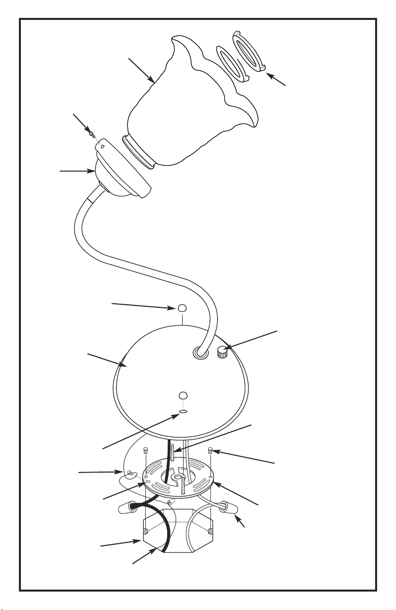
FIGURE 1.
THUMB
HOLDER (M)
SCREWS (N)
GLASS
SHADE (L)
RETAINING
RING (O)
PLATE
(if applicable)
*NOT SUPPLIED
BACK PLATE (B)
GREEN
GROUNDING
SCREW (H)
CAP NUTS (A)
BACK PLATE
OPENING (J)
SIDE
HOLE (I)
BOX (E)
*OUTLET
GROUND
WIRE
POWER
SWITCH (K) (if applicable)
MOUNTING
SCREWS (D)
SCREWS (F)
*OUTLET BOX
UNIVERSAL
MOUNTING
PLATE (C)
Line art shown may not exactly match the fixture enclosed.
WIRE
CONNECTORS (G)
However, the installation instructions do apply to this fixture.
3

MOUNTING AND WIRING INSTRUCTIONS
NOTE: Underwriters Laboratories (UL) does not require all fixtures to have ground wires. These
fixtures meet all UL specifications.
1. Turn off power at circuit box to avoid possible electric shock.
2. Remove cap nuts (A) from back plate (B) and remove universal mounting plate or cross bar
(C), leaving mounting screws (D) in place (see fig. 1).
3. Secure universal mounting plate or cross bar (C) to outlet box (E) with outlet box screws (F)
(not included).
4. Identify color coding of fixture wires (see fig. 2 on page 11).
5. To connect wires, take black fixture wire (group A from fig. 2) and place evenly against
black outlet boxwire. Do not twist wires.
6. Fit wire connector (G from fig. 1) over wires and twist until there is a firm connection. If
wire connector (G) easily comes off, reattach and check again for a firm connection.
7. Repeat steps 5 and 6 with the white (group B from fig. 2) fixture
8. Partially thread green grounding screw (H) into side hole (I) on universal mounting plate or
cross bar (C) (see fig.1).
9. Wrap ground wire from fixture around green grounding screw (H) leaving enough excess wire to
then connect ground wire and outlet box wire with wire connector (G), if applicable.
10. Tighten green grounding screw (H). Do not over tighten.
11. Tuck wires inside outlet box (E) (see fig. 1).
and outlet box wires.
FIXTURE ASSEMBLY INSTRUCTIONS
Warning: This fixture is for indoor use only.
1. Position back plate (B) over mounting screws (D) by aligning back plate openings (J) with
mounting screws (D).
NOTE: Position back plate with power switch (K) pointed downward.
2. Secure with cap nuts (A).
3. Install glass shade (L) and plate (if applicable) into holder(s). Secure with thumb screws or
ring(s) (O), whichever is applicable.
4. Install lamp(s). Do not exceed recommended wattage.
5. Turn power back on at circuit box.
4
 Loading...