

Page 1
WARNING:
Manufacturers Model No.
PS4, PS4ASIC, R4, R4ASIC
401AT
R5VI-ICA, R5VI-S-ICA, R6VI-ICA, R6VI-S-
EL7IC100A, EL99
SCIBX, IBX4-120, BX4-120, FT4
Y7, Y7ICAT
Risk of re or electric shock. Disconnect power to existing luminaire at breaker box. Luminaries' wiring,
ballasts, or other electrical parts may be damaged when drilling for installation of the converter kit hardware. Check for
enclosed wiring and components. Do not alter, relocate, or remove wiring, lampholders, ballasts, or any other electrical
components. Install in 4" to 6" recess can luminaires that have the construction features and dimensions as shown in the
drawings on page 2 of this instruction sheet. To prevent wire damage, do not expose wiring to edge of sheet metal or
other sharp objects. The Recessed Light Converter Kit is not intended for installation on inclined ceilings. Mount only on
listed new construction cans with bar hangers. Do not use this product in a pop in can (see
illustration). DO NOT install on t-bar suspended ceilings. 50 lbs. max. load rating for luminaires.
Not intended for luminaires greater than 50 lbs.. Note: This recess light converter kit is
designed to support a luminaire with a maximum weight that can be supported by your
recess can or 50 lbs., whichever is less. Not intended for use with ceiling fan. The converter kit
installation requires knowledge of lighting luminaires electrical system. If not qualied, do not
attempt installation. Contact a qualied electrician.
CONVERT ALL OF THESE RECESSED CAN LIGHT PRODUCTS
EI400AT, H99ICT, H99T EL99, H99ICAT,
H5ICAT, H5T, H5ICAT, ET500, EI500AT,
H25ICAT, H7T, HI7T, H7ICT, H7ICAT,
H7TNB, H7ICTNB, H7ICATNB, H27T,
H27ICT, H27ICAT, ET700, ET2700,
EI700U, EI700UAT, EI700AT, EI700NB,
Halo
Lightolier
Lithonia
Juno
Progress
Thomas
Nora
L&C Lighting / Seagull
L&C Lighting / Utilitec
W.A.C.
Seohyun International / Quantus 82-200IC
Elite
Elco
Capri
Jimway / Cammercial Electric
Luminaire: LUICT-0
Prescolite
Utilitech
EI700ATNB, EI2700, EI2700AT
1004IC, 1004ICN, 1004ICNQ, 1004ICQ,
1004SIC, 1004SICN, 1104IC, 1104ICN,
1104ICNQ, 1104ICQ, 1104SIC, 1104SICN
L3R6, L5, LC6, LCP, LU6, LUP, L7, L7X,
L7XP
, LICJ
IC2, IC2W, IC20, IC20N, IC20S, IC20NW,
IC20W, IC21, IC22, IC22S, IC22W, IC23,
IC23W, TC2, TC2S, TC2W, TC20, TC20S,
IC1, IC1S, IC1W, IC1P, TC1, TC1S
P821-AT, P821-FB, P821-FBFC, P84-AT,
P85AT, P85-FB, P85-TG, P86-TG, P87AT,
P645-AT, P83, P88, P830-TG, P831-AT,
P831-FB, P816-TG, P817-AT
PS1, PS3, PS5SH, PS9, PS5, PS5, PS7IC,
NH-26Q, NH-27Q, NHIC-27Q, NHIC27QAT, NHIC-17/100/AT, NHIC-17QAT,
NHIC-17QNBAT, NHIC-17/100/DW,
NHIC-17/100/DWQAT, NH-501Q, NHIC501QAT, NS-401Q, NS-401QAT, NSIC-
1106, 1107, 1108, 1110,1128, 11028,
11019, 1119, 11007, 11107, 11128,
11119, 1105, 1179
LWSIC1
ICA R-500-N-UA, R-602D-N-ICA, R600D-N-A, R-660S-N-A, R-402S-N-ICA,
R-400S-NA
B4, B4IC, B5IC, B5IC-AT, B6, B6IC,
B6ICAT, B26, B26IC
R5H, EL5IC, EL5ICA, EL7IC, EL7ICA,
EL7ICAT, EL7ICWA, EL7IC100,
R4, R4ASIC, R5, CR1, CR1QP, CR1NB,
CR1NBQP, R9ASIC, CR5, CR5QP, PR1
C7 (H5), C7IC (H1), C7ICA (H3),
HBR5000SIC (H21), CAT7ICATA,
HBR5ICAT, CER105, HBR2000BICAT,
HG2000BA
LUICT-00
BX5, IBX5, IBX5S, IBXHW, IBXS, FT5, FT6,
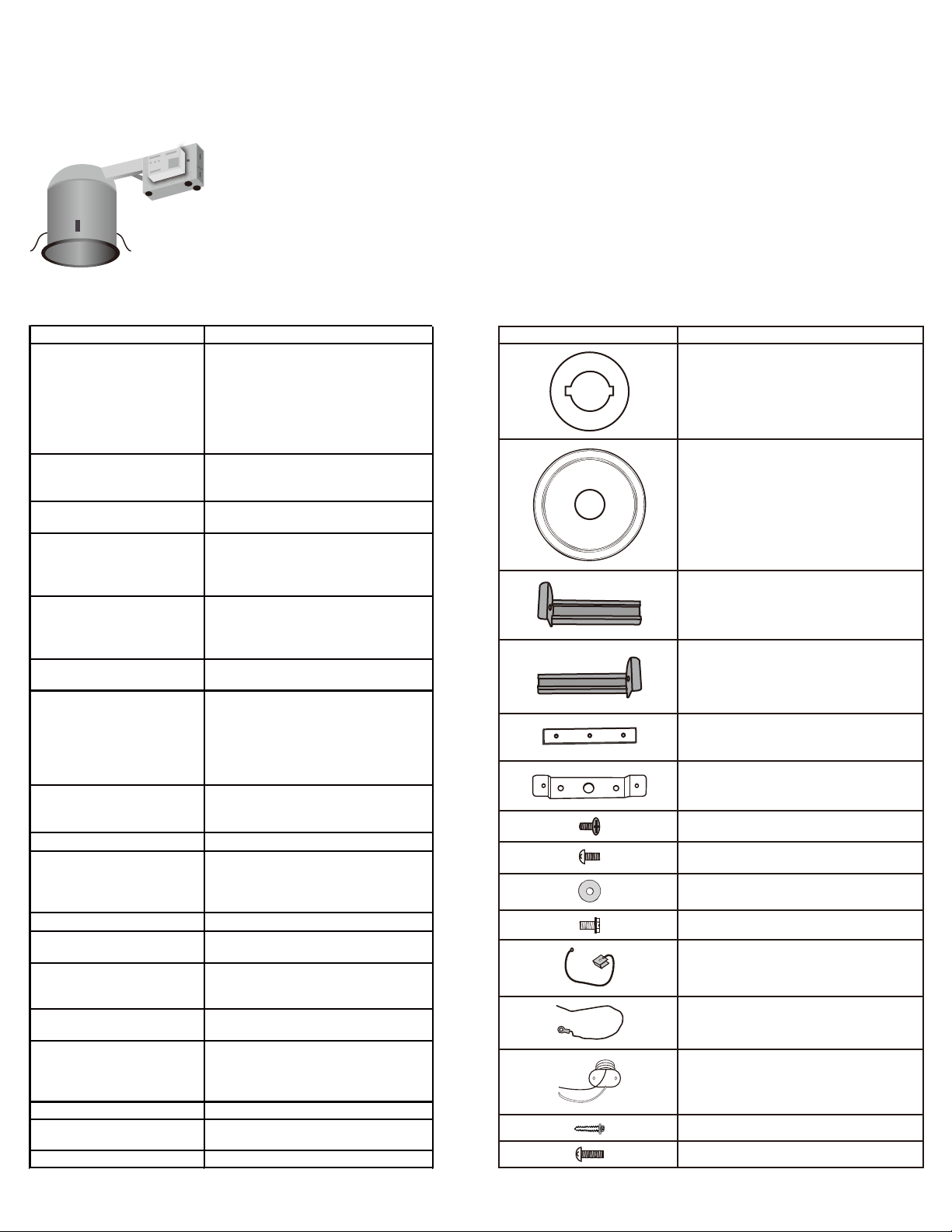
PARTS INCLUDED
Part Description
Metal Cover Plate (A)
Decorative Medallion (B)
Outer Section for
Channel Brace (C)
Inner Section for
Channel Brace (D)
Inner Lock Bar (E)
Crossbar Mounting Bracket (F)
#8-32 x 1/4” Center Screw (G)
#8-32 x 5/16” Side Screw (H)
Washer (I)
#8-32 x 3/16” Gound Screw (J)
Green Ground Wire with screw (K)
Bare Copper Wire (L)
Socket Pigtail (M)
1” Self Piercing Screw (N)
#8-32 x 1/2” Fixture Screw (O)
1
Page 2
Recessed Light Converter
Instruction
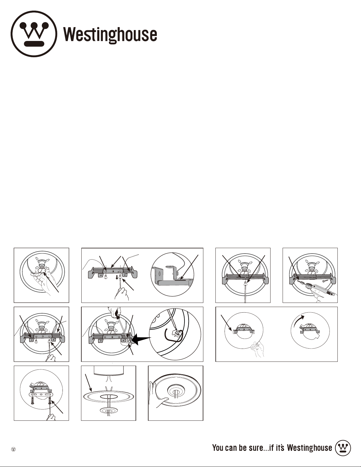
INSTALLATION INSTRUCTIONS
1. Make sure the power is o. Remove the lamp (If applicable) from the socket.
2. Thread the socket pigtail (M) into the recessed can socket (Figure 1).
3. Take of the mounting bracket (F) and the washer (I) from the inner/outer sections for channel brace (C/D) by removing the two
1/4" long side screws (H) (Figure 2).
4. Raise the adjustable channel brace (C/D) into the recessed can and slide the inner and outer sections of the channel brace as
wide as possible, so that the both ends of the brace are against the sides of the recessed can, move the locking bar (E) to the
center of the channel brace, then tighten the center screw (G) (Figure 3).
5. Secure the sliding bar to the recessed can, by using the two supplied 1” long self piercing screws (N). By using a power drill and a
1/4" hexagon driver, drive the two screws through both sides of the channel brace to the side of the recessed can (Figure 4).
Note: Do not use any other type of screw. These screws are specically designed for this application. Only two screws are
needed, two extra screws were provided for your convenience.
6. Install the mounting bracket (F) and the washer (I) back onto the channel brace (C/D), by using the two side screws (H) removed
from step 3 (Figure 5).
Note: The washer must be used for 5” & 6” can installations; Do not use the washer for 4” can installation.
7. Install the green ground wire with screw (K) to the side of the recessed can using ground screw (J) (Figure 6).
8. Raise the metal cover plate (A), rotate it and make sure the mounting bracket holds the metal cover plate in place (Figure 7).
9. Install your lighting xture's mounting bar (Q) (Not included, it comes with the lighting xture purchased separately) on mount
ing bracket (F) with two 1/2" long xture screws (O) (included) (Figure 8). Follow the installation instructions included with your
luminaire to mount onto the recess can converter kit.
10. Insert the lighting xture wires through the decorative medallion center hole (B), and place the decorative medallion onto the
canopy (Figure 9). Note: Decorative medallion is held in place by installed xture.
11. Make the electrical connection between the pigtail (M) and your xture's electrical wires, and raise the decorative medallion and
xture canopy. Secure the canopy according to your lighting xture installation instruction (Figure 10).
C&DF
Figure 1 Figure 2
F
Figure 5
Figure 8 Figure 9 Figure 10
M
C&D
H
Figure 6
B
O
H
J
K
I
E G
Figure 3
A
Figure 7
N
Figure 4
Westinghouse Lighting Corporation
Philadelphia, PA 19154-1029, U.S.A.
Westinghouse Lighting Corporation
a Westinghouse Electric Corporation licensee;
“Westinghouse” and “You can be sure...if it’s Westinghouse”
are all registered trademarks of Westinghouse Electric Corporation
© 2013 WESTINGHOUSE LIGHTING CORPORATION, INC
2
Page 3

ADVERTENCIA:
Fabricantes Modelo No.
EI700ATNB, EI2700, EI2700AT
P831-FB, P816-TG, P817-AT
R5VI-ICA, R5VI-S-ICA, R6VI-ICA, R6VI-S-
R-400S-NA
EL7IC100A, EL99
C7 (H5), C7IC (H1), C7ICA (H3),
LUICT-00
Riesgo de incendios o choques eléctricos. Desconecte la energía de su artefacto de iluminación desde la caja de fusibles.
Los cables de los artefactos, estabilizadores u otros componentes eléctricos podrían sufrir daños durante la perforación para la
instalación de la tornillería del adaptador. Compruebe que los cables y componentes estén protegidos. No altere, cambie de
ubicación o extraiga cables, soportes para lámparas, estabilizadores ni ningún otro componente eléctrico. Instale en artefactos de
iluminación con cajas empotradas de 10 a 15 cm (4 a 6 pulg.) que posean las características de diseño y las dimensiones que se
muestran en los dibujos de la página 4 de esta hoja de instrucciones. Para evitar daños en los cables, evite que entren en contacto
con bordes de metal enchapado u otros objetos cortantes. El juego adaptador para lámparas empotradas no está diseñado para ser
instalado en cielo rasos inclinados. Instale solamente en las cajas de construcción nueva con barras
de suspensión. No usar este producto en una lata para aplicaciones de remodelado (ver ilustración).
NO instale en cielo rasos suspendidos con barra transversal. Capacidad de carga máxima para
artefactos de iluminación de 23 kg (50 libras) No utilizar con artefactos cuyo peso supere los 23 kg
(50 lb). Nota: Este juego adaptador para lámparas empotradas está diseñado para soportar un
artefacto cuyo peso máximo sea compatible con su caja empotrada o sea de 23 kg (50 lb), el que
sea menor. No diseñado para usar con ventiladores de techo. La instalación del juego adaptador
requiere conocimientos sobre el sistema eléctrico para artefactos eléctricos. Si no cuenta con la
capacitación necesaria, no intente realizar la instalación. Consulte a un electricista certicado.
ADAPTE TODOS ESTOS PRODUCTOS DE ILUMINACIÓN
CON CAJAS EMPOTRADAS
EI400AT, H99ICT, H99T EL99, H99ICAT,
H5ICAT, H5T, H5ICAT, ET500, EI500AT,
H25ICAT, H7T, HI7T, H7ICT, H7ICAT,
H7TNB, H7ICTNB, H7ICATNB, H27T,
H27ICT, H27ICAT, ET700, ET2700,
Halo
Lightolier
Lithonia
Juno
Progress
Thomas
Nora
L&C Lighting / Seagull
L&C Lighting / Utilitec
W.A.C.
Seohyun International / Quantus 82-200IC
Elite
Elco
Capri
EI700U, EI700UAT, EI700AT, EI700NB,
1004IC, 1004ICN, 1004ICNQ, 1004ICQ,
1004SIC, 1004SICN, 1104IC, 1104ICN,
1104ICNQ, 1104ICQ, 1104SIC, 1104SICN
L3R6, L5, LC6, LCP, LU6, LUP, L7, L7X,
L7XP, LICJ
IC2, IC2W, IC20, IC20N, IC20S, IC20NW,
IC20W, IC21, IC22, IC22S, IC22W, IC23,
IC23W, TC2, TC2S, TC2W, TC20, TC20S,
IC1, IC1S, IC1W, IC1P, TC1, TC1S
P821-AT, P821-FB, P821-FBFC, P84-AT,
P85AT, P85-FB, P85-TG, P86-TG, P87AT
P645-AT, P83, P88, P830-TG, P831-AT,
PS1, PS3, PS5SH, PS9, PS5, PS5, PS7IC,
PS4, PS4ASIC, R4, R4ASIC
NH-26Q, NH-27Q, NHIC-27Q, NHIC27QAT, NHIC-17/100/AT, NHIC-17QAT,
NHIC-17QNBAT, NHIC-17/100/DW,
NHIC-17/100/DWQAT, NH-501Q, NHIC501QAT, NS-401Q, NS-401QAT, NSIC401AT
1106, 1107, 1108, 1110,1128, 11028,
11019, 1119, 11007, 11107, 11128,
11119, 1105, 1179
LWSIC1
ICA R-500-N-UA, R-602D-N-ICA, R600D-N-A, R-660S-N-A, R-402S-N-ICA,
B4, B4IC, B5IC, B5IC-AT, B6, B6IC,
B6ICAT, B26, B26IC
R5H, EL5IC, EL5ICA, EL7IC, EL7ICA,
EL7ICAT, EL7ICWA, EL7IC100,
R4, R4ASIC, R5, CR1, CR1QP, CR1NB,
CR1NBQP, R9ASIC, CR5, CR5QP, PR1
,
PARTES INCLUIDAS
Parte Descripción
Cubierta protectora de metal (A)
Medallón decorativo (B)
Sección externa
para brazo de jación (C)
Sección interna
para brazo de jación (D)
Barra de jación interna (E)
Soporte transversal de montaje (F)
Tornillo central No. 8-32 x 6,4 mm (1/4 pulg.) (G)
Tornillo lateral No. 8-32 x 7,9 mm (5/16 pulg.) (H)
Arandela (I)
Tornillo de tierra No. 8-32 x 4,8 mm (3/16 pulg.) (J)
Cable verde de tierra con tornillo (K)
Cable de cobre sin aislamiento (L)
HBR5000SIC (H21), CAT7ICATA,
HBR5ICAT, CER105, HBR2000BICAT,
Jimway / Cammercial Electric
Luminaire: LUICT-0
Prescolite
Utilitech
HG2000BA
BX5, IBX5, IBX5S, IBXHW, IBXS, FT5, FT6,
SCIBX, IBX4-120, BX4-120, FT4
Y7, Y7ICAT
Espiral del portalámparas (M)
Tornillo autoperforante de 25 mm (1 pulg.) (N)
Tornillo de artefacto No. 8-32 x 13 mm (1/2 pulg.) (O)
3
Page 4

Instrucciones para Adaptador
para Lámparas Empotradas
INSTRUCCIONES DE INSTALACIÓN
1. Asegúrese de que el suministro eléctrico esté desconectado. Extraiga la lámpara (si corresponde) del portalámparas.
2. Enrosque la espiral del portalámparas (M) en el portalámparas de la caja empotrada (Figura 1).
3. Retire el soporte de montaje (F) y la arandela (I) de las secciones interna y externa del brazo de jación (C/D) extrayendo los dos tornillos
laterales de 6,4 mm (1/4 pulg.) de largo (H) (Figura 2).
4. Eleve el brazo de jación ajustable (C/D) hacia dentro de la caja empotrada y deslice las secciones interna y externa del brazo de jación para
separarlas lo máximo posible de modo que ambos extremos del brazo traben contra los laterales de la caja empotrada, desplace la barra de
jación (E) hacia el centro del brazo de jación y luego ajuste el tornillo central (G) (Figura 3).
5. Fije la barra deslizante a la caja empotrada usando los dos tornillos autoperforantes de 25 mm (1 pulg.) de largo (N) incluidos. Usando un
taladro y una punta hexagonal de 6,4 mm (1/4 pulg.), haga que ambos tornillos pasen a través de ambos lados del brazo de jación hacia los
laterales de la caja empotrada (Figura 4).
Nota: No use ningún otro tipo de tornillo. Estos tornillos están especícamente diseñados para esta aplicación. Solo se requieren dos tornillos
pero se incluyen dos tornillos adicionales para su comodidad.
6. Vuelva a colocar el soporte de montaje (F) y la arandela (I) sobre el brazo de jación (C/D) usando los dos tornillos laterales (H) que extrajo en
el paso 3 (Figura 5).
Nota: La arandela debe ser usada para instalar cajas de 13 y 15 cm (5 y 6 pulg.). No utilice la arandela para la instalación de cajas de 10 cm (4 pulg.)
7. Instale el cable verde de tierra con el tornillo (K) sobre el lateral de la caja empotrada usando el tornillo de tierra (J) (Figura 6).
8.
Eleve la cubierta protectora de metal (A), gírela y asegúrese de que el soporte de montaje sostenga la cubierta protectora de metal en su sitio (Figura 7).
9. Coloque la barra de montaje de su artefacto de iluminación (Q) (no incluida, se incluye con el artefacto de iluminación que compró por
separado) sobre el soporte de montaje (F) con dos tornillos de 12,7 mm (1/2 pulg.) de largo (O) (incluidos) (Figura 8). Siga las instrucciones de
instalación incluidas con su artefacto de iluminación para montarlo sobre el juego adaptador para cajas empotradas.
10. Introduzca los cables del artefacto de iluminación a través del oricio central del medallón decorativo (B) y coloque el medallón decorativo
sobre el dosel (Figura 9). Nota: El artefacto instalado mantiene el medallón decorativo en su sitio.
11. Haga la conexión eléctrica entre el espiral (M) y los cables eléctricos de su artefacto y levante el medallón decorativo y el dosel del artefacto.
Fije el dosel según las instrucciones de instalación de su artefacto de iluminación (Figura 10).
C&DF
Figura 1 Figura 2
F
Figura 5
Figura 8 Figura 9 Figura 10
M
C&D
H
Figura 6
B
O
H
J
K
I
E G
Figura 3
A
Figura 7
N
Figura 4
Westinghouse Lighting Corporation
Philadelphia, PA 19154-1029, U.S.A.
Westinghouse Lighting Corporation
a Westinghouse Electric Corporation licensee;
“Westinghouse” y “You can be sure...if it’s Westinghouse”
son marcas registradas de Westinghouse Electric Corporation
© 2013 WESTINGHOUSE LIGHTING CORPORATION, INC
4
 Loading...