

Westin 21-24010, 21-24015, 21-54000, 21-24000, 21-54005 Installation Instructions Manual
...
INSTALLATION INSTRUCTIONS
PRO TRAXX 4 & 5 OVAL TUBE STEP BAR
AUTOMOTIVE PRODUCTS,
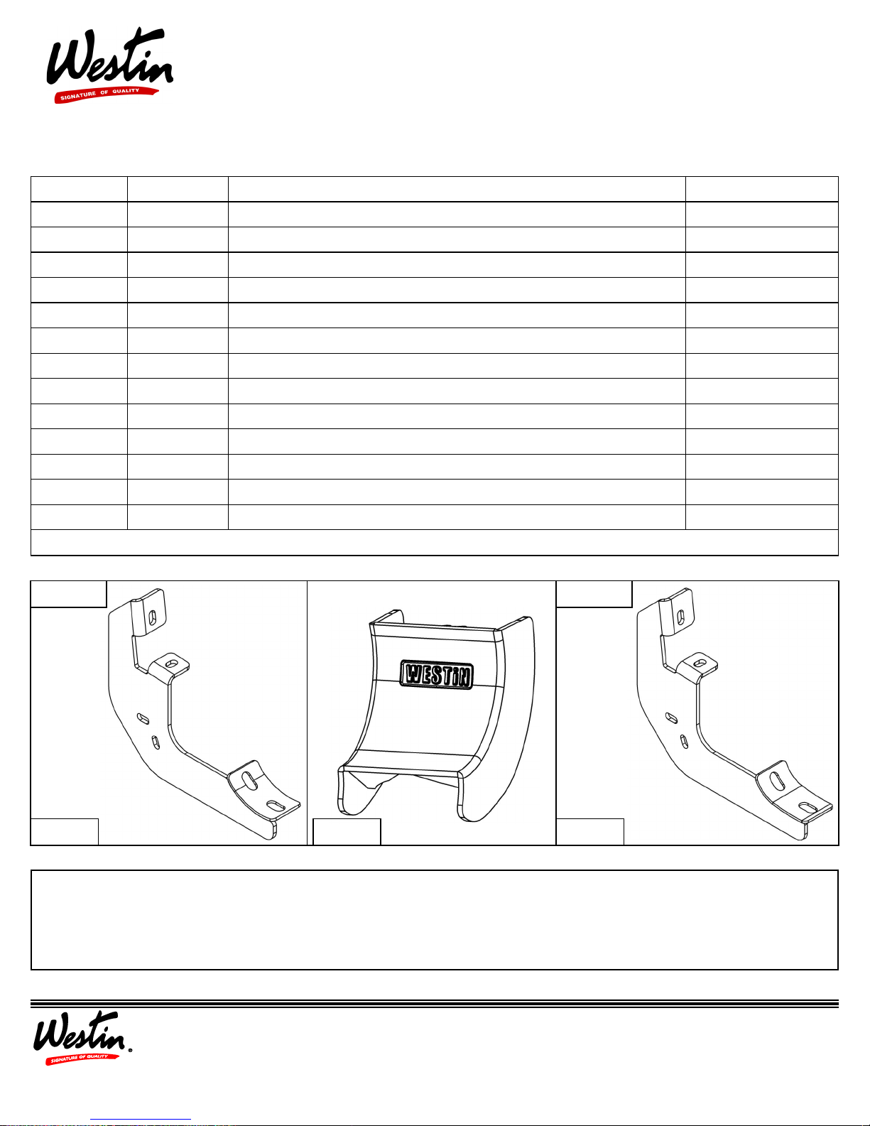
ITEM QUANTITY DESCRIPTION TOOLS NEEDED
1,2 2 STEP BAR, DRIVER(1) AND PASSENGER(2) 13MM SOCKET
3 6 MOUNTING BRACKETS ALLEN WRENCH
4 12 M8 HEX CAP SCREW (YELLOW ZINC) SOCKET EXT.
5 12 M8 FLAT WASHER (YELLOW ZINC) HEX HEY TOOL
6 12 M8 SPLIT LOCK WASHER (YELLOW ZINC) RATCHET
7 12 M8 U-CLIP NUT (YELLOW ZINC) TORQUE WRENCH
8 12 M10 INTERNAL TOOTHED LOCK WASHER (BLACK ZINC)
9 12 M10 FLAT WASHER (BLACK ZINC)
10 12 M10 BUTTON HEAD SCREW (BLACK ZINC)
11 12 M6 HEX HEAD CAP SCREW (BLACK ZINC)
APPLICATION:
2015-+ Chevrolet Colorado / GMC Canyon Extended / Crew Cab
PART NUMBER:
21-24000, 21-24005, 21-24010, 21-24015,
21-54000, 21-54005, 21-54010, 21-54015
12 24 M6 FLAT WASHER (BLACK ZINC)
13 12 M6 NYLON NUT (BLACK ZINC)
14 6 PLASTIC BRACKET COVER
ANTI-SEIZE LUBRICANT MUST BE USED ON ALL STAINLESS STEEL FASTENERS TO PREVENT THREAD DAMAGE AND GALLING
Pro Traxx 5 Pro Traxx 4
ITEM 3
ITEM 3 ITEM 14
PROCEDURE
1. Remove contents from box, verify if all parts listed are present and free from damage.
Carefully read and understand all instructions before attempting installation.
Failure to identify damage before installation could lead to a rejection of any claim.
1
Westin Automotive Products, Inc.
320 W. Covina Blvd
San Dimas, Ca. 91773
P.N.: 75-3085-RevB
ECO #: W16-0069
Thank you for choosing Westin products
for additional installation assistance please call
Customer Service (800) 793-7846
www.westinautomotive.com
DATE: 10/7/16
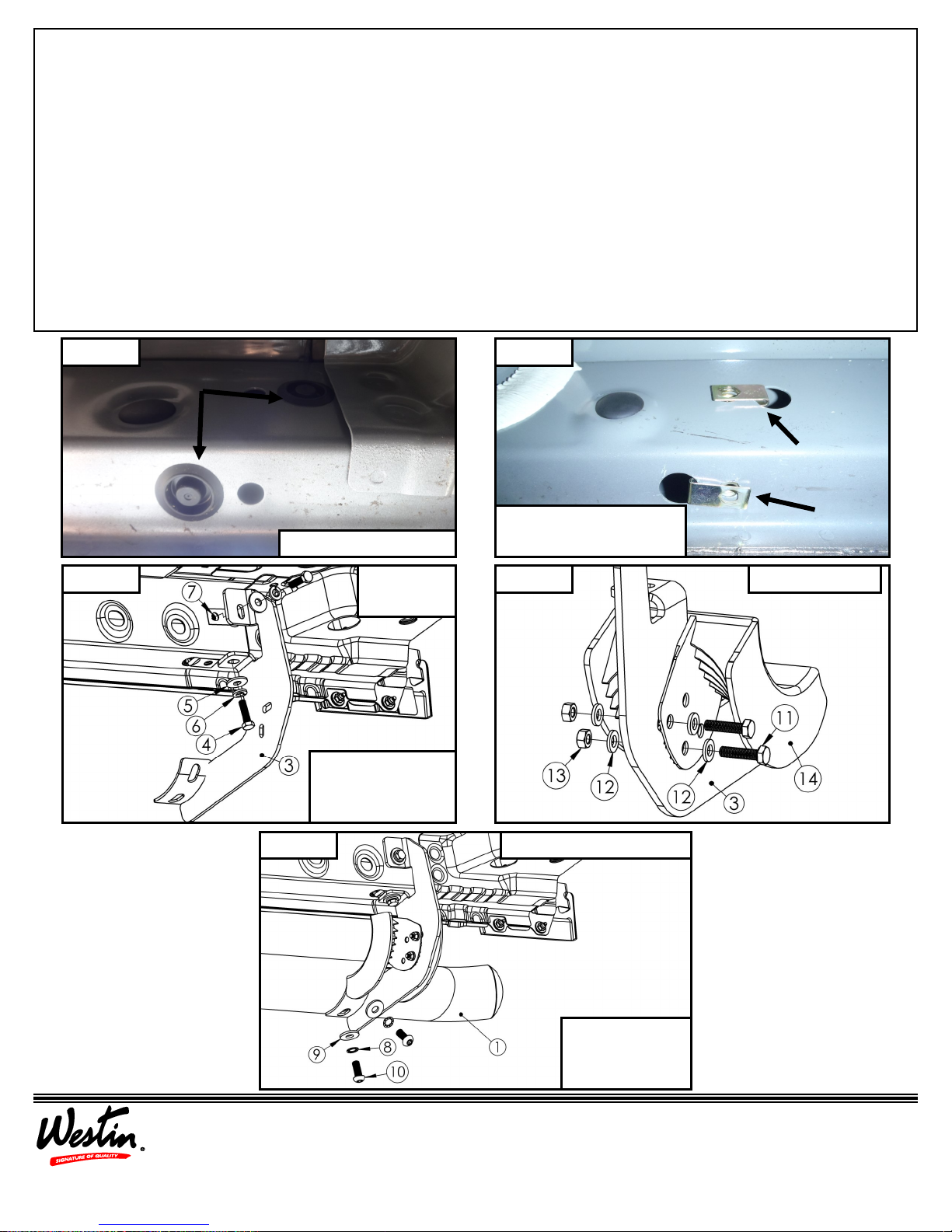
2. If vehicle has plastic covers, remove the designated covers where mounts will be placed from the rocker panel, see Figure
1.
3. Install M8 u-clip nuts in the holes where the plastic covers were removed, see Figure 2. Note: See Figure 6 for placement
of all designated u-clips.
4. Loosely install mounting brackets to the previously install M8 u-clips with supplied M8 hardware. Note: The middle
bracket will be closer the front bracket then in comparison to the rear bracket.
5. Locate (1) plastic bracket cover (Item 14) and loosely secure it to the (6) brackets using the provided hardware: (2) M6 hex
head cap screws, (4) M6 flat washers, and (2) M6 nylon nuts. Repeat for every bracket. See Figure 4.
6. Loosely install the Pro Traxx step bar assembly to the previously installed mounting brackets with supplied M10 hardware.
See Figure 5. Note: Driver side step tube will be packaged in a clear poly tube and passenger side will be pa ckaged
in a red poly tube, the Westin logo should face outward when installed.
7. Align and adjust as necessary then torque hardware: M8 to 15-18 ft-lbs., M10 to 30-35 ft-lbs., and M6 to 5-7 ft-lbs.
Figure 1
Figure 3
Remove rubber covers.
Front Driver
Side Shown
Install mounting
brackets with sup-
plied M8 hardware.
Figure 2
Install supplied M8 u-clip
nuts in designated areas.
Figure 4 Pro Traxx 4 Only
Westin Automotive Products, Inc.
320 W. Covina Blvd
San Dimas, Ca. 91773
P.N.: 75-3085-RevB
ECO #: W16-0069
2
Front Driver Side Shown Figure 5
Install step bar
with supplied
M10 hardware.
Thank you for choosing Westin products
for additional installation assistance please call
Customer Service (800) 793-7846
www.westinautomotive.com
DATE: 10/7/16
 Loading...