


1
Westin Automotive Products, Inc.
320 W. Covina Blvd
San Dimas, Ca. 91773
Thank you for choosing Westin products
for additional installation assistance please call
Customer Service (800) 793-7846
www.westinautomotive.com
P.N.: 75-1008-RevC
ECO #: W15-0151
DATE: 9/10/15
INSTALLATION INSTRUCTIONS
AUTOMOTIVE PRODUCTS,
PLATINUM 4” OVAL STEP BAR (90° BENT END)
APPLICATION:
2010-2015 Dodge Ram 2500/3500 Mega Cab
PART NUMBER:
21-3570, 21-3575, 23-3570, 23-3575, 25-3570, 25-3575, 26-3570
ITEM QUANTITY DESCRIPTION TOOLS NEEDED
1,2 2 SIDE STEP BAR 18MM SOCKET
3,4 2 FRONT MOUNTING BRACKET 19MM SOCKET
5,6 2 FRONT SUPPORT BRACKET 16MM SOCKET
7 2 REAR MOUNTING BRACKET 18MM WRENCH
8,9 2 CENTER MOUNTING BRACKET RATCHET
10,11 2 REAR SUPPORT MOUNTING BRACKET TORQUE WRENCH
12 2 REAR SUPPORT STRAP
13 4 1/2” HEX BOLTS
14 4 1/2” LOCK WASHERS
15 4 1/2” FLAT WASHERS
16 4 M12 BOLT / M10 NUT PLATE
17 2 M12 BOLT PLATE
18 4 M12 FLAT WASHERS
19 4 M12 LOCK WASHERS
20 4 M12 HEX NUTS
21 6 M12 PLASTIC RETAINERS
22 2 M10 BOLT PLATES
23 1 M10 FISH WIRE
24 2 M10 PLASTIC RETAINER
25 8 M10 HEX BOLTS
26 6 LARGE M10 FLAT WASHERS
27 8 SMALL M10 FLAT WASHERS
28 10 M10 LOCK WASHERS
29 6 M10 HEX NUTS
30 4 LONG M8 HEX BOLTS
31 2 SHORT M8 HEX BOLTS
32 4 LARGE M8 FLAT WASHERS
33 2 SMALL M8 FLAT WASHERS
34 6 M8 LOCK WASHERS
ANTI-SEIZE LUBRICANT MUST BE USED ON ALL STAINLESS STEEL FASTENERS TO PREVENT THREAD DAMAGE AND GALLING
2
Westin Automotive Products, Inc.
320 W. Covina Blvd
San Dimas, Ca. 91773
Thank you for choosing Westin products
for additional installation assistance please call
Customer Service (800) 793-7846
www.westinautomotive.com
P.N.: 75-1008-RevC
ECO #: W15-0151
DATE: 9/10/15
PROCEDURE
1. Remove contents from box, verify if all parts listed are present and free from damage.
Carefully read and understand all instructions before attempting installation.
Failure to identify damage before installation could lead to a rejection of any claim.
2. Starting at the driver side-front of the vehicle, remove the tape covering the factory oval holes in the inner body panel located by the front tire, (Fig. 1). Select the M10 Fish Wire, M10 Bolt Plate and M10 Plastic Retainer. Insert the coiled end
of the Fish Wire into the smaller forward slot closest to the front tire opening, (Fig. 1). Feed the Fish Wire back toward and
out of the larger oval hole.
3. Thread the coiled end of the Fish Wire onto the threaded end of the Bolt Plate, (Fig. 2). Carefully pull the straight, forward
end of the Fish Wire until the threaded end of the Bolt Plate is pulled into the forward hole, (Fig. 3). Hold the Bolt Plate in
place and unscrew the Fish Wire. Thread the Plastic Retainer onto the Bolt Plate to hold it in place, (Fig. 4B).
IMPORTANT: The Retainer is designed to keep the Bolt Plate from falling into the body panel and to aid in Bracket installation.
4. Determine correct procedure for your model/year.
Models without factory threaded inserts in body panel:
a. Partially thread a M12 Plastic Retainer onto the threaded end of a M12 Bolt and Nut Plate, (Fig. 5A). Insert
the Bolt and Nut Plate into the larger rear oval hole and tighten the Plastic Retainer, (Fig. 5B). Proceed to Step 5.
Mid 2015-on models with factory threaded inserts:
a. NOTE: The M12 Bolt/Nut Plate is not required for this installation. Skip to Step 5.
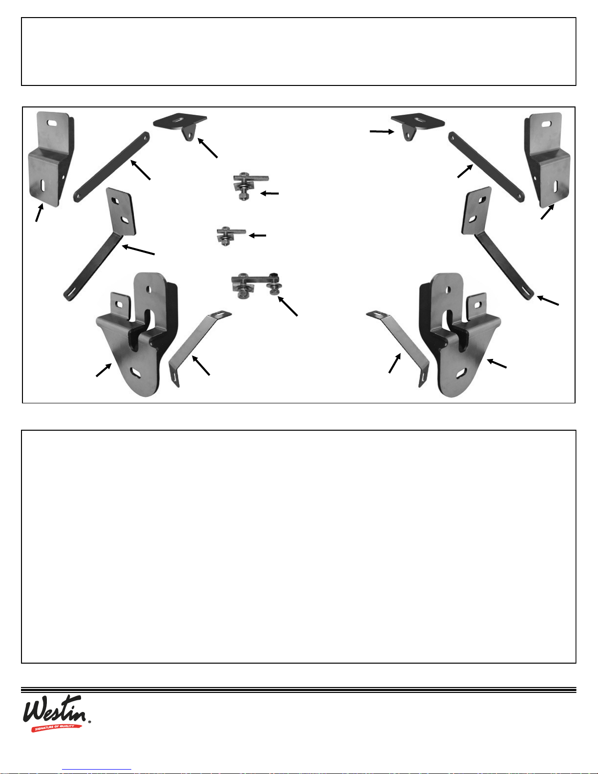
Driver Side
Front Mounting
Bracket
Passenger Side Front
Support Bracket
Passenger Side
Front Mounting
Bracket
Passenger Side
Rear Mounting
Bracket
Driver Side Front
Support Bracket
M10 Bolt Plate
(front bracket only)
M12 Bolt Plate
(rear bracket only)
M12 Bolt / M10 Nut Plate
(front and center brackets only)
Driver Side
Rear Mounting
Bracket
Passenger Side Rear Support
Mounting Bracket
Driver Side Rear Support
Mounting Bracket
Passenger
Side Center
Mounting
Bracket
Rear Support
Strap
Rear Support
Strap
Driver Side
Center
Mounting
Bracket

3
Westin Automotive Products, Inc.
320 W. Covina Blvd
San Dimas, Ca. 91773
Thank you for choosing Westin products
for additional installation assistance please call
Customer Service (800) 793-7846
www.westinautomotive.com
P.N.: 75-1008-RevC
ECO #: W15-0151
DATE: 9/10/15
5. Select the driver side front Mounting Bracket. Position the Mounting Bracket onto the front M10 Bolt Plate. Attach the
Bracket to the Bolt Plate with (1) M10 Flat Washer, (1) M10 Lock Washer, and (1) M10 Hex Nut, (Fig. 6). Do not tighten
at this time.
Driver side up to mid 2015 without factory threaded inserts:
a. Rotate the M12 Bolt and Nut plate until the threaded nut lines up with the remaining hole in the Mounting Bracket
and body, (Fig. 5B). Attach the Bracket to the threaded Nut Plate with (1) M10 Hex Bolt, (1) M10 Lock Washer, and
(1) M10 Flat Washer, (Fig. 6).
Driver side mid 2015-on with factory threaded inserts:
a. Attach the Brackets to the threaded insert with (1) Long M8 Hex Bolt, (1) M8 Lock Washer, and (1) Large M8 Flat
Washer instead of the M10 hardware, (Fig.7). Do not tighten hardware at this time.
Passenger side all model years:
a. Repeat the previous applicable driver side instructions to attach the bottom/rear mounting hole on the passenger side
front Bracket to the Bolt/Nut plate or threaded insert if equipped, (Fig.6 & 7). Do not tighten hardware at this time.
6. Remove the driver side front factory body bolt and washer. Select the driver side Front Support Bracket. Insert the factory
body bolt and washer through the slot in the Support Bracket and up into its original position, (Fig. 8 & 9). Line up the
other end of the Support Bracket with the oval hole in the Front Mounting Bracket. Snug but do not tighten hardware.
7. Move to the mid point on the driver side of the vehicle and remove the tape covering the factory oval hole in the inner
body panel, (Fig. 10B). Select and install a M12 Bolt and Nut Plate with M12 Plastic Retainer as described in Step 3,
(Fig. 10A & 10B).
8. Select the driver side Center Mounting Bracket. Attach the Mounting Bracket to the Bolt and Nut Plate with (1) M12 Flat
Washer, (1) M12 Lock Washer and (1) M12 Hex Nut, (Fig. 11). Rotate the Bolt and Nut plate until the Nut end lines up
with the remaining hole in the Mounting Bracket and body. Thread (1) M10 Hex Bolt, (1) M10 Flat Washer, and (1) M10
Lock Washer into the threaded nut. On models with factory installed threaded insert, use the Bolt and Nut Plate to at-
tach the top of the Bracket but attach the bottom of the Bracket to the threaded insert with (1) Long M8 Hex Bolt, (1) M8
Lock Washer and (1) Large M8 Flat Washer instead of the M10 hardware, (Fig. 11). Do not tighten hardware at this time.
9. Next, move to the rear mounting location and remove the tape covering the single factory hole, (Fig. 12B). Select (1) M12
Bolt Plate and M12 Plastic Retainer, (Fig. 12A). Partially thread the Retainer onto the Bolt Plate. Insert the Bolt Plate into
the factory oval hole. Select (1) Rear Mounting Bracket. Attach the Bracket to the Bolt Plate with (1) M12 Flat Washer, (1)
M12 Lock Washer, and (1) M12 Hex Nut. Push Bracket up against the body as you tighten the hardware, (Fig. 13).
10. Remove the driver side rear factory body bolt and washer. Select the driver side Rear Support Mounting Bracket, (Fig. 14).
Insert the factory body bolt and washer through the Support Mounting Bracket and up into its original position. Next, select (1) Rear Support Strap and bolt it to the mounting tab on the Rear Support Mounting Bracket and to the Rear Mounting Bracket with (2) M10 Hex Bolts, (4) Small M10 Flat Washers, (2) M10 Lock Washers and (2) M10 Hex Nuts, (Fig.
15). Snug but do not tighten hardware at this time.
11. Select the driver Side Step Bar and with assistance, carefully fasten it to the front and rear Mounting Brackets with the included (2) 1/2” Hex Head Bolts, (2) 1/2” Lock Washers, and (2) 1/2” Flat Washers, (Fig. 15 & 16). Do not tighten at this
time.
12. Level and align Side Step Bar properly; then snug all hardware on the front and rear Mounting Brackets first.
13. Line up the Center Mounting Bracket with the threaded insert in the Side Step Bar. Insert (1) Short M8 Hex Bolt, (1) M8
Lock Washer, and (1) M8 STD Flat Washer through the Center Bracket and into the threaded insert in the Sidebar, (Fig.
17). Slowly tighten the Mounting Hardware.
14. Check the Side Step Bars for level and adjust as necessary. Tighten all hardware at this time.
 Loading...