

Westhold TXDP-01 Instructions

Installation Instructions – Hard Wired Transmitter
1. Strip the leads back to expose the copper wire. Be careful not to damage
the wire when stripping.
2. Attach one lead to +12 volts and the other lead to the body frame of the
vehicle that the ground (negative) terminal of the battery is connected to. It
does not matter whether the red or black lead is connected to +12 volts and
ground as long as one is at +12 volts and the other is grounded.
Current drawn by the transmitter is low. However the transmitter should be
connected in such that the transmitter is disengaged when the vehicle is not
running.
**Do not exceed +14 volts or the transmitter may be damaged.
3. When power is delivered to the transmitter both the red and green LED
lights will turn on momentarily. The red LED will shut off and the green
LED light will flash approximately once a second to indicate that the
transmitter is operational.
If only the red LED light is on, it indicates voltage is too low for normal
operation. Do not allow the voltage to go below +9 volts.
Description Specification
Voltage +14 > Voltage > +9V
Current < 30 milliamps
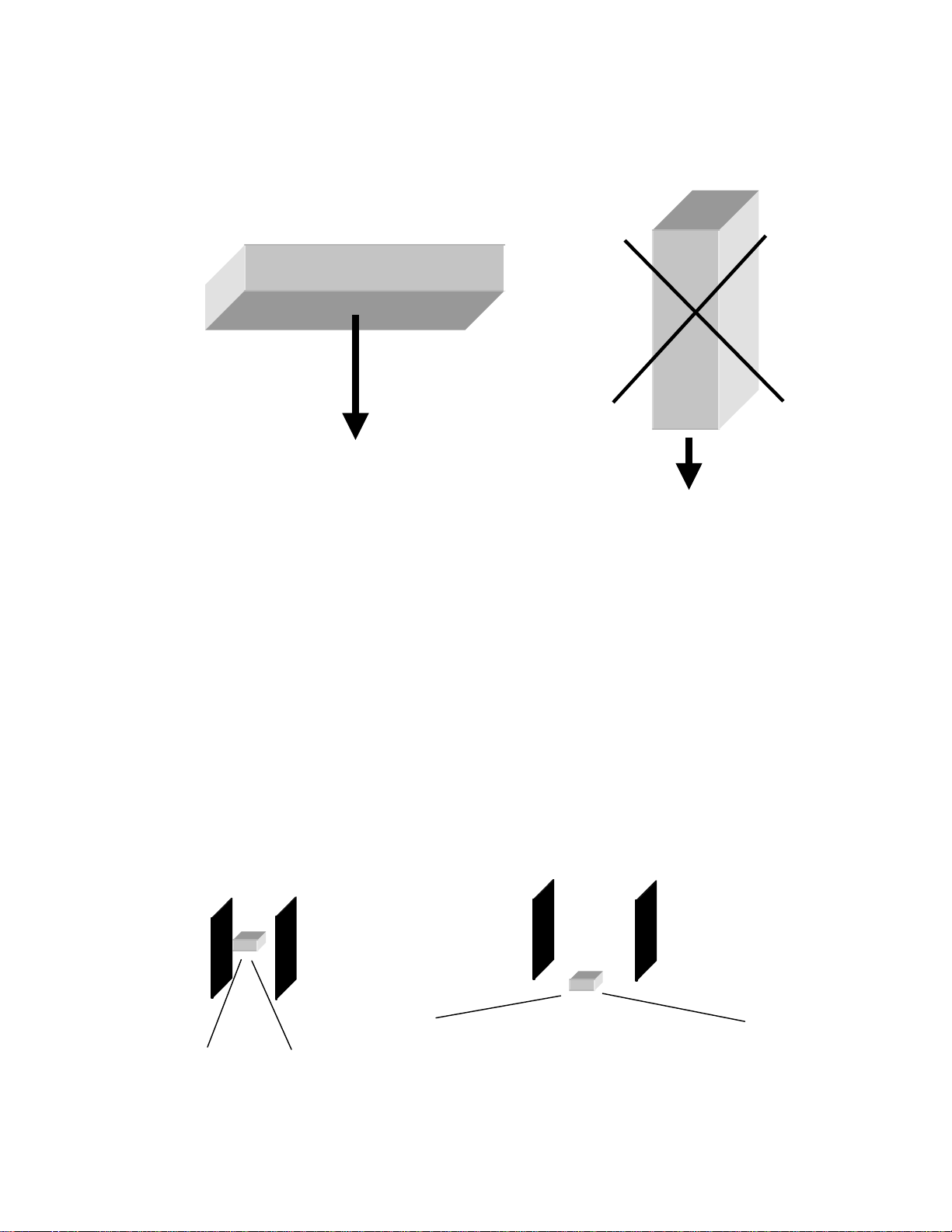
Transmitter Mounting
p
• Label side of the transmitter faces down toward the track.
Note: There are other systems that use a different orientation such as the one on the right. Be careful
about mixing the orientations.
• No metal or carbon fiber between transmitter and track. The transmitter must have a
clear shot to the ground.
Note: Signals can go through plastic so it is possible to use a piece of plastic as a mounting plate.
It is possible to recess the transmitter, however keep in mind that recessing the
transmitter can create problems such as shown below.
1) The label side should face down toward the track.
2) No metal should be between the label and the track.
Poor location: Narrow window for
detection. The signal can’t be seen well.
This is a poor orientation and
will result in inconsistent
erformance.
Good location: No metal to block the signal.
The detection window is very wide.
 Loading...