

Page 1
WESTGATE MFG., INC | 2041 DAVIE AVE, COMMERCE, CA 9004 0, United States | 1-323-826-9490 | [email protected]
WESTGATE
INSTALLATION INSTRUCTION MANUAL
LED WALLPACKS LIGHT, 100-277VAC
Rev A October 2013
MODELS:
LWP-20aa; LWP-30aa;
Model number parameter list:
CAUTION: This product use an input 100-277VAC driver of wide range voltage, but the actual working voltage is depend on
the input voltage of the photocell that installed on the product. Normally the input voltage of photocell is
120V/208V/240V/277V single range, and also have 120-277VAC wide range. Please pay attention when installation.
1. Introduction
This LED Wall-Packs ligh t uses the latest in solid state lighting technology for long life, low
maintenance, and high efficiency.
The same as traditional HID lighting, it could be mounted a standard photocell on the enclosure, to
make it completely suitable for street lighting.
An internal power-factor-corrected switch-mode supply allows it to be used from
any nominal 100V-277V, 60Hz AC supply without any variation in light output.
Suitable for use in the following locations:
•
Ambient Temp: -20~+40°C
•
Wet Locations
Note: Save these instructions for future reference.
2. Installation
Item Model Input Voltage Power Factor Watt Input Current Weight
A
LWP-20aa
100-277VAC ≥0.92
20W 0.3A --Kg
B
LWP-30aa
30W 0.38A --Kg
Warning:
To avoid the risk of fire, explosion, or electric shock, this product should be installed,
inspected, and maintained by a qualified electrician only, in accordance with all applicable
electrical codes.
Warning:
To avoid electric shock:
•Be certain electrical power is OFF before and during installation and maintenance.
•Luminaire must be connected to a wiring system with an equipment-grounding conductor.
Page 2
WESTGATE MFG., INC | 2041 DAVIE AVE, COMM ERCE, CA 90040, United States | 1-323-826-9490 | [email protected]
For supply connections use wire rated for at least 80°C
Installation:
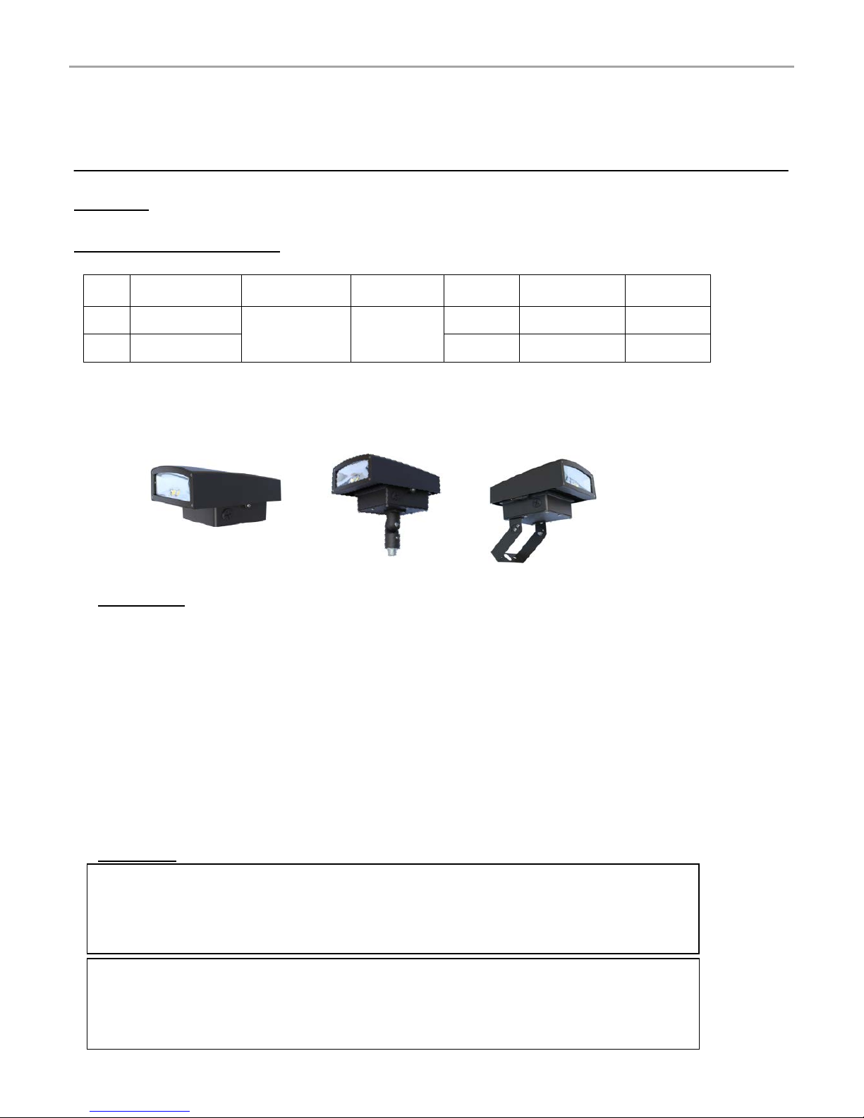
Three mounting kits for option:
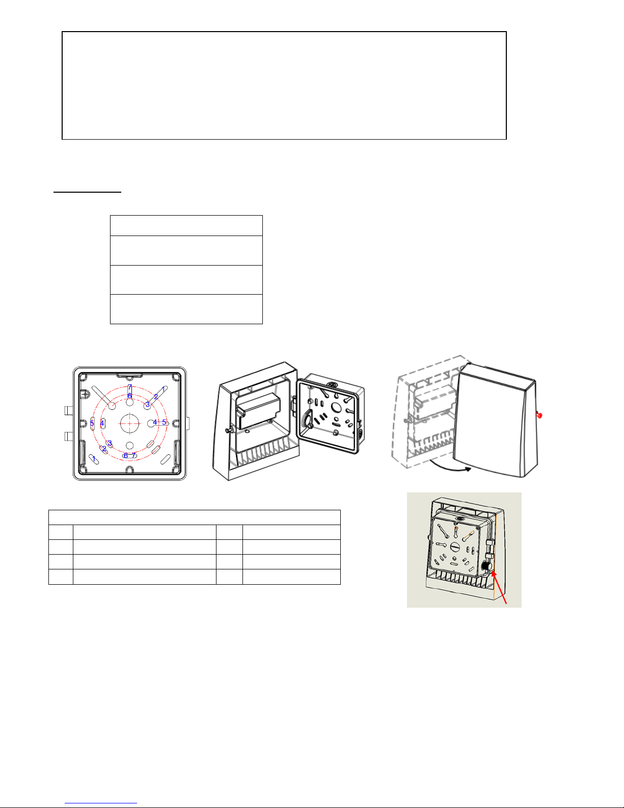
1. Junction Box Mounting
Junction Box Mounting Guide
1-1 4" Square Box 5-5 4" Round Box
2-2
4" Octagonal Box
6-6
2-3/4" Hole Pattern
3-3 3-1/2" Square/Octagonal Box 7-7 Single Gang
4-4 Masonry Box
Step 1
Open the back box by using philips screw driver (FIG.2),confirm junction box size PRIOR to removing the
gasket material for the application (FIG. 1). ONLY remove the gasket material needed for the installation.
Mount back box to junction box via supplied hardware or lag mount. Utilize any junction box pairings for lag
mount (Example: 5-5). Lag mount hardware provided by others.
Type
Wall Mount Lu m inaire
(Junction Box Mounting)
Knuckle Kit
(Mounting Pole)
Trunnion Kit
(Mounting Stand)
Warning:
To avoid explosion:
•Make sure the supply voltage is the same as the rated luminaire voltage.
•Do not install where marked operating temperatures exceed the ignition temperature of
the hazardous atmosphere.
•Do not operate in ambient temperatures above those indicated on the luminaire
nameplate.
FIG.1
FIG.2
FIG.3
FIG.4 Photocell
Page 3
WESTGATE MFG., INC | 2041 DAVIE AVE, COMM ERCE, CA 90040, United States | 1-323-826-9490 | [email protected]
Step 2
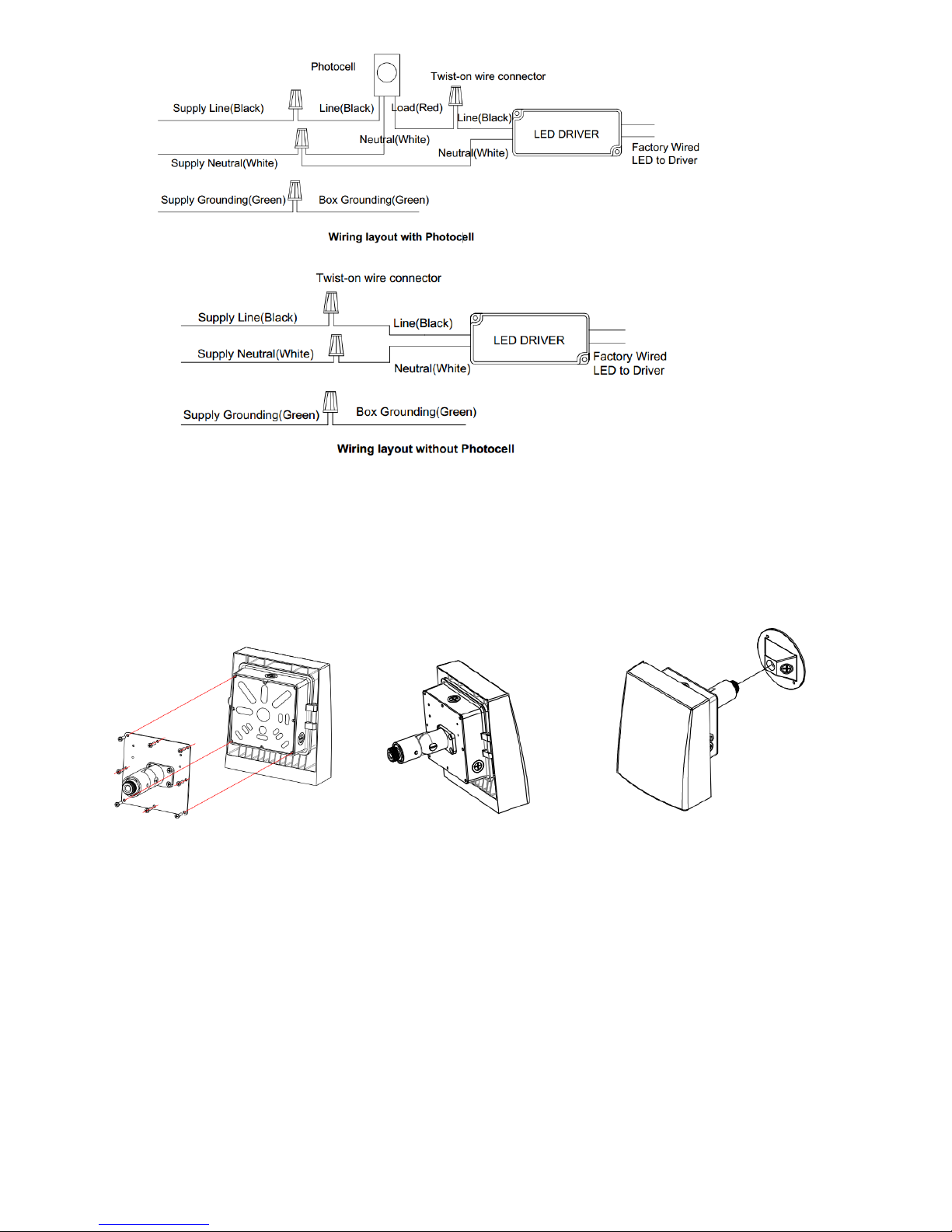
Utilize twist-on connectors to make electrical connections (FIG. 5, 6). All electrical connections must remain
inside back box. Fasten the wires by a provided cable tie, prior to closing and securing enclosure. Tighten
enclosure screw to seal fixture. (FIG.3)
Step 3
Please refer to FIG.4 for location for the photocell (Optional).
2. Mounting Pole
Step 1
Screw the Mounting Pole on the back box (FIG.7, 8)
Step 2
Please refer to FIG.5 or FIG.6 for wiring, remove the screw at the knuckle of the Mounting Pole by screw
driver,put the wires pass through the hole of the Mounting Pole.
Step 3
Route electrical leads through the 1/2" NPS cover plate (supplied by others).
Seal knuckle threads with sealing compound (provided by others).
Secure cover plate to knuckle with lock nut (50-60 in-lbs). Make wire connection in outdoor rated junction
box. Mount cover plate to junction box. (FIG.9)
FIG.7 FIG.8
FIG.9
FIG.5
FIG.6
Page 4
WESTGATE MFG., INC | 2041 DAVIE AVE, COMM ERCE, CA 90040, United States | 1-323-826-9490 | [email protected]
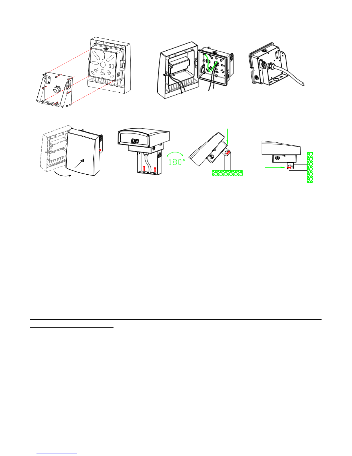
3. Mounting Stand
Step 1
Screw the Mounting Stand on the back box(FIG.10)
Step 2
Open the back box,put the wires (SJTW 18AWG/3C)(provided by others) into the back box from the strain
relief, twist the stain relief tightly (FIG.11), refer to FIG.5 or FIG.6 for wiring.
Step 3
Lock the enclosure (FIG.12), mount the trunnion on mounting surface, direction could be adjusted (FIG.13,
14).
After installation, please
check whether the lighting fixture is firmly fixed.
check whether wires are connected correctly.
At last, turn on the power, and check if the lighting fixture works well. If not, please turn off the power
and contact with local dealer.
Warning: the luminaire shall be installed by qualified electrician.
FIG.10 FIG.11
FIG.12 FIG.13 FIG.14
 Loading...