

Page 1
SHERWOOD INDUSTRIES IS AN ENVIRONMENTALLY RESPONSIBLE COMPANY. THIS MANUAL IS PRINTED ON RECYCLED
PLEASE KEEP THESE INSTRUCTIONS FOR FUTURE REFERENCE
PAPER.
DV62
B Y : S H E R W O O D I N D U S T R I E S L T D
TECHNICAL
MANUAL
INSTALLER:
Leave this manual with the appliance.
CONSUMER:
Retain this manual for future reference.
WHAT TO DO IF YOU SMELL GAS
• Open windows/extinguish any open
ame.
• Do not try to light any appliance.
• Do not touch any electrical switch; do
not use any phone in your building.
• Immediately call your gas supplier
from a neighbour’s phone. Follow the
gas supplier’s instructions.
• If you cannot reach your gas supplier,
call the re department.
FOR YOUR SAFETY: Do not store or use gasoline or
other ammable vapours and liquids in the vicinity of
this or any other appliance.
WARNING: If the information in this manual is
not followed exactly, a re or explosion may result
causing property damage, personal injury or loss of
life. Installation and service must be performed by a
qualied installer, service agency or the gas supplier.
This appliance may be installed in an
after-market permanently located,
where not prohibited by local codes.
This appliance is only for use with
the type of gas indicated on the
rating plate. This appliance is not
convertible for use with other gases,
unless a certied kit is used.
Massachusetts installations (Warning): This product must be installed by a licensed plumber or
gas tter when installed within the Commonwealth of Massachusetts. Other Massachusetts code
requirements: Flexible connector must not be longer than 36in., a shut off valve must be installed;
only direct vent sealed combustion products are approved for bedrooms/bathrooms. A carbon
monoxide detector is required in all rooms containing gas red direct vent appliances. The replace
damper must be removed or welded in the open position prior to installation of a replace insert.
50-2163
Page 2
Safety PrecautionS
FOR SAFE INSTALLATION AND OPERATION OF YOUR “WESTGATE”
HEATER, PLEASE CAREFULLY READ THE FOLLOWING INFORMATION:
• All Westgate gas-red appliances must be installed
in accordance with their instructions. Carefully read all
the instructions in this manual rst. Consult the building
authority having jurisdiction to determine the need for a
permit prior to commencing the installation.
• NOTE: Failure to follow these instructions could
cause a malfunction of the replace, which could result in
death, serious bodily injury, and/or property damage.
• Failure to follow these instructions may also void
your re insurance and/or warranty.
GENERAL
• Installation and repair should be done by a qualied
service person. The appliance should be inspected before
the rst use and, at least, annually by a qualied service
person. More frequent cleaning may be required due to
excessive lint from carpeting, bedding material, etc. It
is imperative the control compartments, burners and
circulating air passageways of the appliance be kept
clean.
• Due to high temperatures, the appliance should be
located out of high trafc areas and away from furniture
and draperies.
Children and adults should be alerted to the
hazards of high surface temperatures and should
stay away to avoid burn or clothing ignition.
• Young children should be carefully supervised when
they are in the same room as the appliance, Toddlers,
young children and others may be susceptible to accidental
contact burns. A physical barrier is recommended if there
are at risk individuals in the house. To restrict access to
a replace or stove, install an adjustable safety gate to
keep toddlers, young children and other at risk individuals
out of the room and away from hot surfaces.
• Clothing or other ammable materials should not be
placed on or near the appliance.
• To prevent injury, if the pilot or pilot and
burners have gone out on their own, open the
glass door and wait 5 minutes to air out before
attempting to re-light the replace.
• Always keep the area around these appliances clear
of combustible material, gasoline and other ammable
liquids and vapours.
• These appliances should not be used as a drying
rack for clothing or for hanging Christmas stockings/
decorations.
• Due to the paint curing on the replace, odor and
slight smoking will likely be noticed when the replace is
rst used. Open a window until the smoking stops.
Always connect this gas replace to a vent system and
vent to the outside of the building envelope. Never vent
to another room or inside the building. Make sure the
specied vent pipe is used, properly sized and of adequate
height to provide sufcient draft. Inspect the venting
system annually for blockage and signs of deterioration.
WARNING: Failure to position the parts in accordance
with the diagrams in this booklet, or failure to use only
parts specically approved with this appliance, may result
in property damage or personal injury.
WARNING: Do not operate with the glass front removed,
cracked or broken. Replacement of the glass should be
done by a licensed or qualied service person.
• Never use solid fuels such as wood, paper, cardboard,
coal, or any ammable liquids, etc., in this appliance.
• Do not use this heater if any part has been under
water. Immediately call a qualied service technician to
inspect the heater and to replace any part of the control
or gas control systems that have been under water.
• Do not abuse the glass by striking it or slamming the
door shut.
FOR YOUR SAFETY
• Installation and service must be performed by a
qualied installer, service agency or gas supplier.
• This installation must conform to local codes or, in the
absence of local codes, to the current CAN/CSA-B149.1
Natural Gas and Propane Installation Code (Canada) or
National Fuel Gas Code ANSI Z223.1.2 (USA)
• To prevent injury, do not allow anyone who is
unfamiliar with the replace to operate it.
2
WARNING
HOT GLASS WILL
CAUSE BURNS
DO NOT TOUCH GLASS
UNTIL COOLED.
NEVER ALLOW
CHILDREN TO TOUCH
GLASS.
Page 3

table of contentS
Safety Precautions..........................................................................................2
Table of Contents............................................................................................3
Codes And Approvals......................................................................................4
Specications.................................................................................................5
Dimensions........................................................................................5
Rating Label Location..........................................................................5
Rating Label.......................................................................................6
Planning Your Installation................................................................................7
Introduction.......................................................................................7
Non-Combustible Material Zone............................................................7
Typical Framing - Internal Chase..........................................................8
Typical Framing - External Chase..........................................................9
Typical Framing - Corner:...................................................................10
Typical Framing - Sidewall and Mantel.................................................11
Typical Framing - Raised Hearth.........................................................12
Installation of Facing Trim..................................................................13
Installation of Fireplace Facing...........................................................14
Installation of Receiver.......................................................................16
Allowable Vent Congurations............................................................17
Vent Termination Restrictions.............................................................18
Approved Vent Parts..........................................................................19
Installation of Flue Restrictor..............................................................20
Planning Your Installation..................................................................21
Assembly of the Unit.........................................................................21
Securing unit into Position.................................................................21
Installation Set-Up........................................................................................22
Installation Of Non-combustible Wall ..................................................22
Installation Of Venting And Terminations.............................................23
Horizontal Installation........................................................................23
Vertical Termination Installation..........................................................26
Door Removal and Installation...........................................................28
Gas Hook-Up.....................................................................................29
Electrical Hook-Up.............................................................................30
Firebox Liner Installation...................................................................30
Log Burner / Ember Bed Installation...................................................32
Log Set Installation...........................................................................34
Glass Burner Installation...................................................................39
Porcelain Panel Kit Installation............................................................41
Optional Front Installation.................................................................44
Wiring Harness.............................................................................................45
Diagnostic Flash codes..................................................................................46
Troubleshooting............................................................................................47
Parts Diagram...............................................................................................49
Parts Diagram - Options................................................................................50
Parts List......................................................................................................51
Warranty......................................................................................................53
Installation Data Sheet..................................................................................54
3
Page 4
codeS and aPProvalS
DIRECT VENT ONLY: This type is identied by the prex DV. This appliance draws all of its air for
combustion from outside the dwelling, through a specially designed vent pipe system.
In the USA: The appliance may be installed at higher altitudes. Please refer to your American Gas
Association guidelines which state: the sea level rated input of Gas Designed Appliances installed at
elevations above 2000 (610 m) feet is to be reduced 4% for each 1000 feet (305 m) above sea level.
Refer also to National Fuel Gas Code, ANSI Z223.1/ NFPA 54, local authorities, or codes which have
jurisdiction in your area regarding the de-rate guidelines.
In Canada: When the appliance is installed at elevations above 4500 feet (1372 m), the certied high
altitude rating shall be reduced at the rate of 4% for each additional 1000 feet (305 m). Refer also
to CSA-B149.1 Natural Gas and Propane Installation Code, local authorities, or codes which have
jurisdiction in your area regarding the de-rate guidelines.
• This appliance has been tested by LabTest Certication Inc. and found to comply with the
established VENTED GAS FIREPLACE HEATER standards in CANADA and the USA as follows:
VENTED GAS FIREPLACE HEATER (DV62)
TESTED TO: ANSI Z21.88-2009/CSA 2.33-2009 VENTED GAS FIREPLACE HEATERS
CAN/CGA 2.17-M91 GAS FIRED APPLIANCES FOR HIGH ALTITUDES
CSA P.4.1-R2009 TESTING METHOD FOR MEASURING ANNUAL FIREPLACE EFFICIENCY
This Westgate DV62 Fireplace:
• Has been certied for use only with natural gas.
• Is not for use with solid fuels.
• Is approved for bedroom or bed sitting room. (IN CANADA: must be installed with a listed wall
thermostat. IN USA: see current ANSI Z223.1 for installation instructions.)
• Must be installed in accordance with local codes. If none exist, use current
installation code CAN/CSA-B149.1 Natural Gas and Propane Installation
Code in Canada or ANSI Z223.1/NFPA 54 in the USA.
• Must be properly connected to an approved venting system and not connected
to a chimney ue serving a separate solid-fuel burning appliance.
• The ow of combustion and ventilation air not be obstructed.
IMPORTANT NOTICE (Regarding rst re up): When the unit is turned
on for the rst time, it should be turned onto high without the fan on for
the rst 4 hours. This will cure the paint, logs, gasket material and other
products used in the manufacturing process. It is advisable to open a
window or door, as the unit will start to smoke and can irritate some people.
After the unit has gone through the rst burn, turn the unit off including the
pilot, let the unit get cold then remove the glass door and clean it with a
good gas replace glass cleaner, available at your local WESTGATE dealer.
4
Page 5

Dimensions:
SPecificationS
Rating LabeL Location:
The Rating and Lighting instruction label is located below the door frame,
underneath the rebox attached to a chain. To access the label, slide the
plate forward out from under the rebox. Always return it when nished.
Figure 1. Dimensions of the Firebox.
Figure 2. Rating/Lighting Label Location.
5
Page 6

Rating LabeL:
SAMPLE
SPecificationS
6
Figure 3. Rating Label.
Page 7

Planning your inStallation
intRoDuction:
This section of the technical manual is for the use of qualied technicians only. Fireplace placement, hearths,
facings, mantles, and venting terminations will be covered, as well as the gas and electric systems. There are
several installation safety guidelines that must be adhered to. Please carefully read the safety precautions at the
front of this manual.
Warning: Clearances must be sufcient to allow access for maintenance and service.
If installing a Power Vent Kit (50-1970) refer to the instructions included with the kits to aid in your planning.
non-combustibLe mateRiaL Zone:
This installation guide will show you many options for installing your new DV62. Some options include external
chases, internal chases, rock facing and corner installations. No matter what direction your installation takes, this
illustration shows an area where combustible building products may NOT go. This illustration applies to any and all
installations for the DV62 and should be used as the rst reference before any others. Failure to comply with this
requirement can lead to elevated operating temperatures, degradation of materials or even result in re. If you are
un-clear about any details contained here, consult with your retailer prior to installation.
Figure 4. Non-Combustible Material Zone.
7
Page 8

Planning your inStallation
typicaL FRaming - inteRnaL chase:
Figure 5. Typical Framing for Internal Chase - General.
Figure 6. Typical Framing for Internal Chase - Detailed.
8
Page 9

Planning your inStallation
typicaL FRaming - exteRnaL chase:
Figure 7. Typical Framing for External Chase - General.
Figure 8. Typical Framing for External Chase - Detailed.
9
Page 10

Planning your inStallation
typicaL FRaming - coRneR:
Figure 9. Typical Framing for Corner - General.
Figure 10. Typical Framing for Corner - Detailed.
10
Page 11

Planning your inStallation
typicaL FRaming - siDewaLL anD manteL:
The mantel’s maximum overhang is 12”
(300mm) at the minimum height of 62”
(1575mm) measured from the base of
the replace.
The mantel can extend 1” (25.4mm)
further for every 1” (25.4mm) of height
it is installed over the minimum height.
Non-combustible mantels and
mantel legs are not limited to these
dimensions.
Mantel temperatures are monitored
during testing and can reach 117°F
(47°C) above room temperatures.
Make sure the nish on your mantel
is suitable for temperatures of this
range.
Figure 11. Typical Framing for Sidewalls & Mantel - General.
Figure 12. Typical Framing for Sidewalls & Mantel - Detailed.
11
Page 12

Planning your inStallation
typicaL FRaming - RaiseD heaRth:
Warning: Failure to follow these guidelines may result in elevated operating temperatures,
an inability to remove or install the door, or install the optional front that are
available for this unit.
A non-combustible Hearth
Insulation Board is not required
for the DV62.
If a hearth is to be installed in
front of the unit , it must not
be thicker than ¾” . If the
hearth is raised or the hearth
materials is thicker than ¾”,
the unit must be spaced up
by the same distance that the
hearth materials extended
beyond the ¾” limit.
Example:
Hearth material is 2” limestone.
The hearth thickness limit is
¾”, therefore the unit must
be raised up 1¼” off the oor
so that the hearth does not
extend vertically beyond the
bottom ange of the replace.
The DV62 can be installed
directly on top of combustible
ooring. If the unit needs
to raise up off the oor, a
wooden structure can be built
to accommodate the raised.
Placing a couple of thicknesses
of plywood under the unit would
be an acceptable method.
Figure 13. Typical Framing for a Raised Hearth - General.
12
Figure 14. Typical Framing for a Raised Hearth - Detailed.
Page 13

Planning your inStallation
instaLLation oF Facing tRim:
Figure 15. Facing Trim Installation - General.
13
Page 14

Planning your inStallation
instaLLation oF FiRepLace Facing:
Figure 16. Typical Facing for the Fireplace - General.
The DV62 may be installed
with an optional front.
The front lift on and off
of the replace, providing
access to the replace for
regular maintenance and
service, see Optional Front
Installation.
You have 3 possible
scenarios when installing
facing to your replace.
Care must be taken to
ensure proper clearances are
maintained. Clearances are
required between optional
front and any stone work
applied to your replace
installation. Failure to
maintain this clearance will
lead to elevated operating
temperatures and possible
discoloration of materials
and or front.
Three (3) possible installations include:
1) For replace facing without an optional front installed.
2) For replace facing greater than 1” thick with an optional front installed.
3) For any replace less than 1” thick (total facing and non-combustible board combined) with an optional
front installed.
Figures 17 to 19 highlight the relationships between the replace, optional front, and facing installed.
NOTE: Optional Door Front cannot be installed with the Porcelain Firebox Liner option.
Figure 17. Option 1 - Fireplace Facing Without Optional Front Installed
When installing the DV62 without the optional door sets, install the inner trim kit that is supplied with the unit.
The inner trim is fastened to the non-combustible wall board that comes with the unit and the rock/tile facing
covers over the trim ange as with any typical drywall ange. The rock or tile facing can be any thickness, but
once this unit is installed, you can no longer install the optional door sets
14
Page 15

Planning your inStallation
instaLLation oF FiRepLace Facing continueD:
Figure 18. Option 2 - Fireplace Facing More Than 1” (25.4mm) Thick With
Optional Fronts Installed.
When installing the DV62 with the optional door and you plan to install rock or tile facing that is thicker than 1”
(combined with the non-combustible board supplied), you must install the wall trim kit that is supplied with the
unit. The optional wall trim is fastened to the non-combustible wall board that comes with the unit and the rock
or tile facing covers over the trim ange as with any typical drywall ange. The minimum air gap shown on the
drawing must be maintained between the optional door set and the wall as well as between the facing and the
door set as shown.
Figure 19. Option 3 - Fireplace Facing Less than 1” (25.4mm) Thick
When installing the DV62 with the optional door and you plan to install rock or tile facing that is thinner than
1” (combined with the non-combustible board supplied), you do not need to install any optional trim. The
minimum air gap between the optional door set and the wall must be maintained as shown. Failure to maintain
this air gap will result in elevated operating conditions.
With Optional Fronts Installed.
15
Page 16

Planning your inStallation
instaLLation oF ReceiveR:
NOTE: Finish receiver install
after all other construction
to avoid damage
Figure 20. Receiver Installation.
The Receiver is the heart of the remote control system. You need to access this receiver after installation to
change the batteries (for operation during a power failure), to program a new remote / receiver combination
and to operate a manual override should you lose your remote control or the batteries in the remote control
lose their power.
The Receiver is connected to the replace with a wire harness that has a maximum length of 8 ft (2.4m). The
connection point on the replace is on the right side of the unit, where the gas valve and electronic ignition
module is located. Because of the 8 ft (2.4m) limitation in the wiring harness, the receiver needs to be mounted
to the right side of the replace. An electrical box is provided for the receiver. Mount this electrical box as you
would any electrical outlet or switch box. Thread the cable and connector through the back of the electrical
box and connect it to the rear of the receiver. Secure the receiver into the electrical box. Once the facing of
the replace installation is complete, install the receiver cover, supplied with the unit as shown. The receiver
cover also functions as a switch plate and allows for access to the program button, critical for remote control
operation.
Review the section in this manual regarding the remote control operations for more information on the functions
of the receiver.
aLLowabLe vent conFiguRations:
The vent chart, in Figure 21, illustrates the vent congurations that have been tested and approved for use with
this appliance. 45˚ elbows are acceptable for this installation and may be used instead of 90˚ elbows. You may
use two (2) 45˚ elbows for every 90˚ elbow shown in this chart.
This appliance can be used with 5” x 8” venting in vertical termination installation with the used of Simpson 5”
x 8” reducer adapter.
The restrictor settings shown in Figure 21, are recommended. Installation factors such as altitude, prevailing
weather conditions such as temperature or wind, or the number of elbows used may affect your nal restrictor
settings. Insufcient restriction may cause pilot outages or reduced efciencies. Too much restriction may lead
to elevated operating temperatures, poor ame appearances, sooting or carbon deposits building up on burner
effects or window glass.
16
Page 17

Planning your inStallation
Figure 21. Allowable Vent Congurations Chart.
17
Page 18
Planning your inStallation
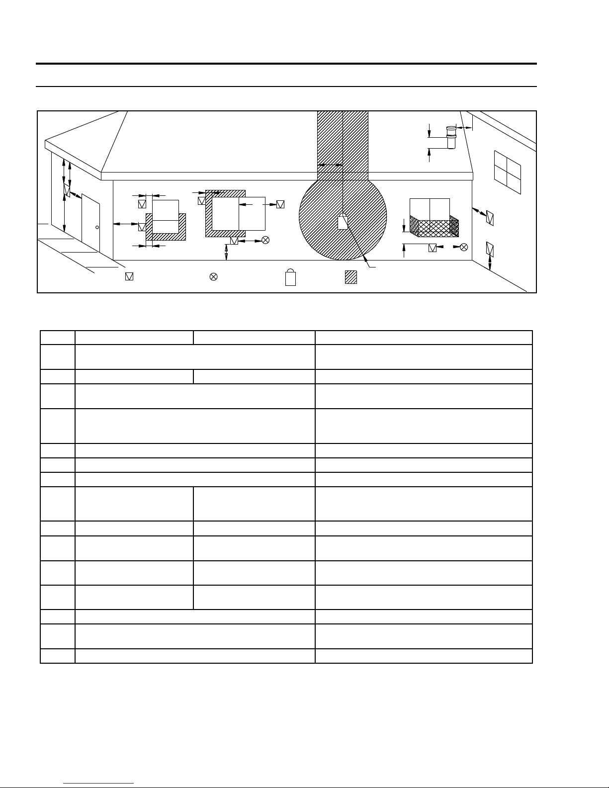
vent teRmination RestRictions:
QUALIFIED INSTALLERS ONLY
N
O
D
E
C
B
L
F
Fixed
Closed
Openable
B
B
Openable
Fixed
Closed
H
G
G
M
B
A
J
I
Termination Cap
Figure 22. Vent Termination Restrictions, refer to Table 1.
Table 1: Vent termination clearances, refer to Figure 22.
Letter Canadian Installation
A 12 in (30 cm) Clearance above grade, verandah, porch, deck, or
B 12 in (30 cm) 9 in (23 cm) Clearance from window or door that may be opened.
C 12 in (30 cm)* Clearance from permanently closed window (to prevent
D 30 in (77 cm) Vertical clearance to ventilated soft located above the
E 30 in (77 cm) Clearance to unventilated soft.
F 12 in (30 cm)* Clearance to outside corner.
G 12 in (30 cm) Clearance to inside corner.
H 3 ft (91 cm) within a height
of 15 ft (4.5 m) above the
meter/regulator assembly
I 3 ft (91 cm) 3 ft (91 cm)* Radial clearance around service regulator vent outlet.
J 12 in (30 cm) 9 in (23 cm) Clearance to non-mechanical air supply inlet to building,
K 6 ft (1.83 m) 3 ft (91 cm) above if within 10
L 7 ft (2.13 m
M 12 in (30 cm)
N 12 in (30 cm)* Clearance horizontally to any surface (such as an exte-
O 12 in (30 cm) Clearance above roof line for vertical terminations.
1
)t
Air Supply Inlet
US Installation
3 ft (91 cm) within a height
of 15 ft (4.5 m) above the
meter/regulator assembly*
ft (3 m) horizontally
7 ft (2.13 m)
+
2
*t
Gas MeterG
balcony.
condensation).
terminal, within a horizontal distance of 2 ft (60 cm)
from center line of terminal.
Clearance to each side of center line extended above
meter/regulator assembly.
or the combustion air inlet to any other appliance.
Clearance to mechanical air supply inlet.
Clearance above paved sidewalk or paved driveway
located on public property.
Clearance under verandah, porch, deck, or balcony.
rior wall) for vertical terminations.
Restriction Zone
(Termination not allowed)
Description
K
A
1
In accordance with the current CSA B149, Natural Gas and Propane Installation Code.
2
In accordance with the current ANSI Z223.1 NFPA 54, National Fuel Gas Code.
* These numbers are only estimates. Clearance in accordance with installation codes and the requirements of the gas supplier.
t
A vent shall not terminate directly above a side walk or paved driveway that is located between two single family dwellings and it serves both dwellings.
+
Permitted only if verandah, porch, deck, or balcony is fully open on a minimum of two sides beneath the oor.
NOTE: Venting terminals shall not be recessed into walls or siding.
18
Page 19
Planning your inStallation
appRoveD vent paRts:
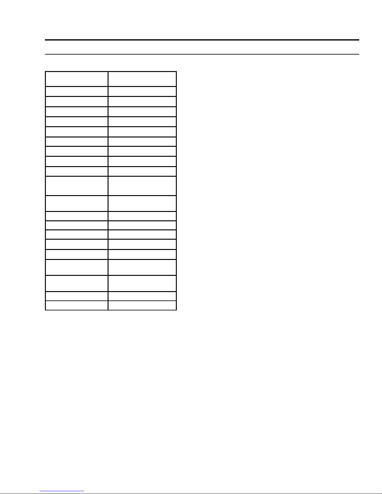
Table 2: Vent part numbers (Must state if galvanized or black wanted, PART NUMBERS).
Part Description Simpson Duravent
6” Pipe Length
12” Pipe Length
24” Pipe Length
36” Pipe Length
48” Pipe Length
12`Adjustable Length
45° Elbow
90° Elbow
90° Elbow (swivel)
Adjustable Roof Flashing
0/12 - 6/12
Steep Roof Flashing 7/12
- 12/12
Elbow Strap
Wall Strap
Storm Collar
Ceiling Firestop
Wall Thimble
Horiz. Termination, High
Wind
Vert. Termination, High
Wind
Vinyl Siding Standoff
5” x 8” Reducer Adapter
662492666098
662492877241
662492779163
662492486399
662492429266
662492606360
662492654897
662492646984
662492863695
662492760871
662492384497
662492864975
662492794630
662492323151
662492471715
662492144596
662492641439
662492723951
662492314067
TBA
IMPORTANT: This chart covers the major components only. Refer to the manufacturers’ catalogue for further details
on roof ashings and other installation items
The DV62 replace has been tested and certied for use with SIMPSON DURAVENT TYPE GS PIPE FOR GAS
STOVES. When planning an installation, it will be necessary to select the proper length of vent pipe for the
particular requirements.
WARNING: Do not mix parts from different vent manufacturers’ systems.
19
Page 20
Planning your inStallation
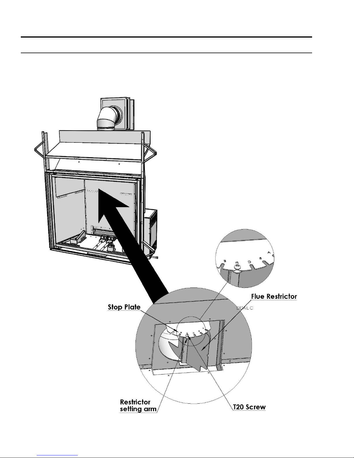
instaLLation oF FLue RestRictoR:
Flue Restrictor is necessary to keep the replace running at its intended efciency. They are also required to
counteract the effect that taller vertical vent runs may have on the appliance. The additional venting action that tall
vertical vent systems may have can result in poor pilot and/or burner operations and possibly nuisance shut downs.
Generally, the vent restriction may be less than what is shown in the vent chart, but not greater.
The DV62 has a built in adjustable ue restrictor.
Set the ue restrictor before you install the
rebox liners. The ue restrictor pivots in the
middle and is secured with a T20 screw. Refer
to the Venting Chart (Figure 21) to determine
the correct setting. The vent chart shows the
range of vent setups that you can use when
installing the DV62. The vent chart shows an
appropriate restrictor setting for the vent run
that you are using.
The vent chart is a starting
point for the restrictor
setting. Environment
factors can affect the
restrictor setting such as
altitude, prevailing weather
and wind conditions. Keep
in mind that running a
restrictor setting that is
more restrictive than the
recommended setting
may result in the replace
running at elevated
temperatures which
can result in hazardous
conditions. Do not leave
an installation without
securing the vent restrictor.
Figure 23: Installation of Flue Restrictor - Close-Up.
20
Page 21

inStallation Set-uP
QUALIFIED INSTALLERS ONLY
pLanning youR instaLLation:
Prior to starting your venting installation, refer to the section on Allowable Vent Congurations to make sure your
plans fall into the allowable limits of horizontal and vertical installations.
When planning your installation, it will be necessary to select the proper length of vent pipe for your particular
requirements. For horizontal installations, refer to the section on Clearances to Combustibles to determine the
minimum clearance from the rear of the appliance to the wall. It is also important to note the wall thickness. Select
the amount of vertical rise desired for “vertical-to-horizontal” type installations. To determine the length of vent
pipe required for vertical installations, measure the distance from the appliance ue outlet to the ceiling, the ceiling
thickness, the vertical rise in an attic or second story, and allow for sufcient vent height above the roof line. For
two-story applications, restops are required at each oor level. If an offset is needed in the attic, additional pipe
and elbows will be required.
assembLy oF the unit:
1.Using eight (8) T-20 screws provided,
install the drywall supports right and left
as well as the heat shield in the middle, as
shown in Figure 28.
2.Using eight (8) T20 screws provided,
attach back stand-offs, as shown in Figure
24.
secuRing unit into position:
Figure 25: Securing the Unit.
Figure 24: Installation of Supports, Heat
shield & Stand-off.
Once the unit is in its nal position,
conrm that you have access to
power, gas supply, that your noncombustible zone requirements
are met, that you meet all the
minimum vent requirements, and
that your planned vent terminal
location will meet all of the vent
termination clearances. Secure
the unit to the oor, with at
least four (4) wood screws, two
(2) on either side of the unit’s
bottom nailing ange. Secure the
side stand-offs to the framing
members using four (4) wood
screws, one (1) for each stand-off
and to the header, one (1) wood
screw for each drywall support.
21
Page 22
inStallation Set-uP
instaLLation oF non-combustibLe waLL boaRD:
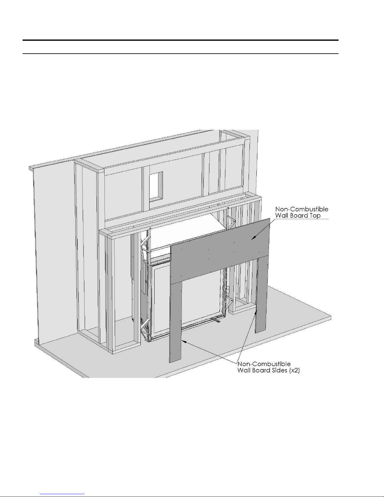
Install the non-combustible wall board provided with the unit. The side boards are interchangeable and are secured
with drywall screws, three (3) to each side of the unit and three (3) to each side frame member. The top board is
secured with four (4) drywall screws along the top frame (header), four (4) along the top nailing ange of the unit
and two (2) on each vertical frame member. Also secure the top wall board to the heat shield behind it with two (2)
screws and each drywall support upright with two (2) screws. See the section on hearth installation for installing
the hearth protector, required with the installation of this unit. All the screws required to attach the wall board sides
and top to the unit have corresponding holes already located on the units nailing anges, drywall supports and heat
shield.
Figure 26: Installation of Wall Board
22
Page 23

inStallation Set-uP
instaLLation oF venting anD teRminations:
Read all instructions carefully before starting the installation. Failure to follow these instructions may create a re
or other safety hazard, and will void the warranty.
INSTALLATION PRECAUTIONS:
• Do not install any damaged venting or vent components.
• Do not modify any vent or termination component.
• Do not install any vent component that is not an approved vent component for this appliance.
• Do not use any instructions other that those included in this manual or those included by the vent component
manufacturer with the venting. When there are discrepancies between the two, this manual will be considered
the nal authority.
Consult your local building codes before beginning the installation.
WARNING
• Always maintain required clearances (air spaces) to nearby combustibles to prevent a re hazard.
Do not ll air spaces with insulation. Unless stated otherwise, clearances on horizontal vent sections
are 2” (51mm) to combustible materials. Clearances to vertical vent sections are 1” (25mm) to
combustible clearances.
• The replace and vent system must be vented directly to the outside of the building. Each direct
vent replace must use its own separate vent system. Common vent systems are prohibited.
• The ow of combustion and ventilation air not be obstructed.
hoRiZontaL instaLLation:
Step 1. Set the replace in its desired location. Check to determine if wall studs or roof rafters are in the way when
the venting system is attached. If this is the case, you may want to adjust the location of the appliance.
Step 2. Direct Vent pipe and ttings are designed with special twist-lock connections. Assemble the desired
combination of pipe and elbows to the appliance. See the sections on Typical Framing - inTernal chase,
exTernal chase or corner insTallaTion for some of the possible vent pathway options. All installations must
fall within the Allowable Vent Congurations shown in Figure 21.
Notes:
(1) Twist-lock procedure: Four (4) indentations, located on the female
ends of pipes and ttings, are designed to slide straight onto
the male ends of adjacent pipes and ttings, by orienting the
four pipe indentations so they match and slide into the four (4)
entry slots on the male ends. Push the pipe sections completely
together, then twist-lock one section clockwise approximately
one-quarter turn, until the two (2) sections are fully locked.
(2) Horizontal runs of vent must be supported every 3 feet (915mm).
Wall Straps are available for this purpose.
(3) Sealant is only necessary on the outer tube of the GS Pipe. Run a
⅛ inch (3mm) wide bead of sealant around the male end of the
outer sleeve, as shown in Figure 27, and twist-lock the pipes or
ttings together.
Figure 27: Twist-Lock Connection.
Step 3. With the adaptor and pipe attached to the replace, slide the replace into its correct location, and mark
the wall for a rectangular hole of the appropriate size. Use 12.5”x14.75” (318x375mm) hole for 6” x 8-5/8”
pipe, Figure 28. The center of the hole should line up with the center line of the horizontal pipe, as shown
in Figure 30. Cut and frame the hole in the exterior wall where the vent will be terminated. If the wall
being penetrated is constructed of non-combustible material, i.e. masonry block or concrete, a hole with
zero clearance to the pipe is acceptable.
23
Page 24

inStallation Set-uP
Notes:
(1) Any horizontal run of vent
must have a ¼ inch (6mm) rise
for every 1 foot (305mm) of
run towards the termination.
Never allow the vent to run
downward. This could cause
high temperatures and may
present the possibility of a
re.
(2) The location of the horizontal
vent termination on an
exterior wall must meet all
local and national building
codes, and must not be easily blocked or obstructed. Termination
clearances must comply with the VenT TerminaTion resTricTions
section.
Step 4. Attach the termination to the termination stand-off
with four screws (refer to Figure 31a). Before attaching the
Vent Termination to the termination stand-off, run a bead of
non-hardening sealant around its outside edges, so as to make
a seal between it and the termination stand-off.
Figure 28:Thimble Framing
Figure 29:Thimble
Step 5. Place the termination assembly against the wall board with
the vent termination center with the cut out hole. Secure the
termination assembly to the exterior wall with eight (8) wood
screws provided (refer to Figure 31b). The arrow on the vent
cap should be pointing up. Ensure that proper clearances to
combustible materials are maintained. Attach intake heat shield
to the termination stand-off with the pre-drill holes (refer to
Figure 32).
Notes:
The eight (8) wood screws provided should be replaced with
appropriate fasteners for stucco, brick, concrete, or other types of
sidings.
Figure 30: Horizontal Venting and Cut Away.
Figure 31a: Attach Termination Stand-off
24
Figure 31b: Fastening Horizontal
Termination Cap in Place.
Page 25

inStallation Set-uP
Step 6. Before connecting the horizontal run of vent pipe to the vent termination, slide the Wall Firestop over
the vent pipe on the interior side of the wall.
Step 7. Slide the appliance and vent assembly towards the wall, carefully inserting the vent pipe into the vent
cap assembly. It is important that the vent pipe extend into the vent cap sufcient distance so as to
result in a minimum pipe overlap of 1¼ inches (32mm).
Step 8. Slide the Wall Firestop up to the wall surface and attach with screws provided (see Figure 33).
Figure 32: Install Intake Heat Shield
Figure 33: Installation of Wall Firestop.
Figure 34: Typical Minimum Vent Congurations
- Horizontally Terminated.
25
Page 26
inStallation Set-uP
veRticaL teRmination instaLLation:
Step 1. M a i n t a i n
c l e a r a n c e s
between venting
and combustible
building materials
as stated earlier
in this section. Do
not pack air spaces
with insulation.
Check with the
Allowable Vent
C o n f i g u r a t i o n s
page when
planning your
installation to
ensure the vertical
and horizontal
elements of your
installation are
within these limits.
Figure 35: Installation of Ceiling Firestop.
Step 2. Set the replace in its desired location. Drop a plum bob down
from the ceiling to the position of the appliance ue exit, and
mark the location where the vent will penetrate the ceiling. Drill a
small hole at this point. Next, drop a plumb bob from the roof to
the hole previously drilled in the ceiling, and mark the spot where
the vent will penetrate the roof. Determine if ceiling joists, roof
rafters, or other framing will obstruct the venting system. You
may wish to relocate the appliance, or to offset, to avoid cutting
load bearing members.
Step 3. To install the Ceiling Firestop in a at ceiling, cut a square hole in the ceiling 11”x11” (280x280mm)
square for 8” x 5” pipe, centered on the hole drilled in Step 2. Frame the hole as shown in Figure 35.
Step 4. Assemble the desired lengths
of galvanized Pipe and Elbows
necessary to reach from the
Appliance Adaptor up through the
Ceiling Firestop. Ensure that all Pipe
and Elbow connections are in their
fully twist-locked position.
Step 5. Cut a hole in the roof centered on
the small drill hole placed in the
roof in Step 2. The hole should
be of sufcient size to meet the
minimum requirements for clearance
to combustibles, as specied earlier.
Continue to assemble lengths of Pipe
and Elbows necessary to reach from
the Ceiling Firestop up through the
roof line.
Figure 36: Vertical Installation using
Wall Straps.
26
Figure 37: Installation of Flashing & Vertical Termination.
Page 27

inStallation Set-uP
Notes:
(1) If an offset is necessary in the attic to avoid obstructions, it
is important to support the vent pipe every 3 feet, to avoid
excessive stress on the Elbows, and possible separation.
Wall Straps are available for this purpose (see Figure 36).
(2) Whenever possible, use 45° Elbows, instead of 90° Elbows.
The 45° Elbow offers less restriction to the ow of ue
gases and intake air.
Step 6. Slip the ashing over the Pipe Section(s) protruding
through the roof. Use a non-hardening sealant
between the Flashing and the roof to prevent water
leakage. Secure the base of the Flashing to the
roof with roong nails. Ensure the roong material
overlaps the top edge of the Flashing as shown in
Figure 37. Verify that you have at least the minimum
clearance to combustibles at the rooine.
Step 7. Continue to add Pipe Sections until the height of
the Vent Cap meets the minimum building code
requirements described by your local codes. In the
absence of local codes, make sure the terminal is
2 feet (610mm) above anything within 10 feet
(3046mm) of the vent (refer to Figure 40 & Table
3 for clearances for different pitches). Note that
for steep roof pitches, the vent height must be increased. In
high wind conditions, nearby trees, adjoining rooines, steep
pitched roofs, and other similar factors can result in poor draft,
or down-drafting. In these cases, increasing the vent height
may solve this problem.
Figure 38: Installation of Ceiling Fire Stops.
Step 8. Slip the Storm Collar over the Pipe, and push it down to the top
of the Flashing, as shown in Figure 38. Use the non-hardening
sealant above and below the joint between the Storm Collar
and the Pipe.
Step 9. Twist lock the Vent Cap.
Notes:
(1) For multi-story vertical installations, a Ceiling Firestop is required at
any subsequent oors (as shown in Figure 38). The opening should
be cut and framed in the same manner as the opening in Step 3 (see
Figure 35).
(2) Any occupied areas above the rst oor, including closets and storage
spaces, which the vertical vent passes through, must be enclosed.
The enclosure may be framed and sheet rocked with standard
construction materials, however minimum allowable clearances
between the outside of the vent pipe must be maintained. Do not ll
any of the required air spaces with insulation.
Figure 39: Typical Vent Congurations
- Vertically Terminated.
27
Page 28
inStallation Set-uP
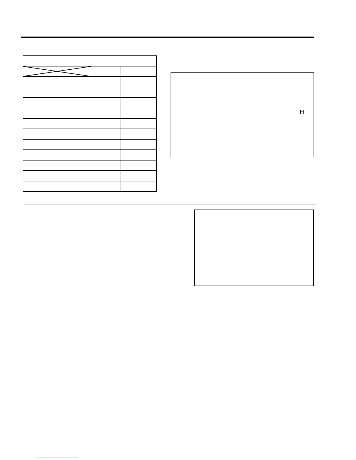
H
Dimension ‘H’ obtained
from table to the left.
Table 3: Minimum ‘H’ for Figure 40.
Roof Pitch Minimum Height (H)
Feet Meters
Flat to 7/12 1 0.3
Over 7/12 to 8/12 1.5 0.46
Over 8/12 to 9/12 2 0.61
Over 9/12 to 10/12 2.5 0.76
Over 10/12 to 11/12 3.25 0.99
Over 11/12 to 12/12 4 1.22
Over 12/12 to 14/12 5 1.52
Over 14/12 to 16/12 6 1.83
Over 16/12 to 18/12 7 2.13
Over 18/12 to 20/12 7.5 2.29
Over 20/12 to 21/12 8 2.44
DooR RemovaL anD instaLLation:
Figure 40: Height of Vertical Termination;
Reference Table 3.
1) The replace door is hung on two (2) hooks on the top of the
rebox. The two (2) door latches at the bottom of the rebox
hook over the tabs on the bottom of the door frame.
2) Lower the door latch tool underneath the door frame. Catch the
lower door latch with the door latch tool (see Figure 41) and
pull it out slightly, then down. Once the lower door latch clears
the tab on the bottom of the door frame, release it inwards and
then remove the door latch tool. Refer to Figures 43 & 44.
3) Pull the Door Frame at the bottom forward about 2” (5cm),
then lift the Door Frame upwards to clear the
Figure 41: Door Latch /Air Adjustment Tool.
28
Figure 43: Door Latch Tool in Place. Figure 42: Door Latch Locations.
Page 29

inStallation Set-uP
4) Lift the Door Frame away, being
careful that the glass panel is secure
within the Door Frame.
gas hook-up:
The DV62 is equipped from factory
with a ½” SAE 45° male gas tting.
This tting will t commonly used
exible gas supply lines.
Figure 44: Door Latch Locations.
If the local code requires to use
rigid pipe for gas supply, nish the
gas line inside the control box,
(through the access hole illustrated)
fasten the pipe to the control box
and complete the connection using
a short length ex line.
NOTES:
This appliance and its main gas
valve must be disconnected from
the gas supply piping system during
any pressure testing of that system
at test pressures in excess of ½ psi
(35 kPa).
Isolate this appliance from the gas
supply piping system by closing its
equipment shutoff valve during any
pressure testing of the gas supply
piping system at test pressures equal
to or less than ½ psi (3.5 kPa).
Figure 45: Location of Gas Hook-Up.
29
Page 30

inStallation Set-uP
eLectRicaL hook-up:
An electrical junction box is provided and fastened to the back of
the control box. Power needs to be brought to the electrical junction
box. The power for the various control components are all provided
from the fan control module. Remove the control box cover, install the
provided electric outlet and cover and plug the fan control module into
it. See the Rating Label for the listed electrical requirements.
When installed, the DV62, must be electrically grounded in accordance
with local codes or, in the absence of local codes, with the National
Electrical Code, ANSI/NFPA 70, or the Canadian Electrical Code, CSA
C22.1.
WARNING
Electrical Grounding Instructions
This appliance is equipped with a three-prong (grounding) plug
for your protection against shock hazard and should be plugged
directly into a properly grounded three-prong receptacle. Do not
cut or remove the grounding prong from this plug.
FiRebox LineR instaLLation:
Figure 46: Location of Electrical Hook-Up.
IMPORTANT: Complete the installation of ue restrictor before proceed the rebox liner installation. The paint
on the panels may fade for the rst 8-10 hours of burn time, but will come back to its color after the paint has
cured. The paint is very delicate and handling them with care is necessary not to mark or smudge the paint.
1) Install the Rear Firebox Liner Panel. This panel rest on top of the rear brick panel support. Hold it with
one hand or have someone else hold it while place in the Left Panel.
2) Install the Left Firebox Liner Panel; it sits on the bottom front edge of the rebox (see Figure 48), a support
bracket at the lower rear of the rebox, and is held in by a retainer at the top of the rebox. Adjust the
panel retainers as required.
3) Install the Top Firebox Liner Panel by placing it on top of the Rear Panel and behind the Left Panel (see
Figure 50 and 51). Hold it with one hand or have someone else hold it for you while you place the last
panel. WARNING: If this panel falls from this location it will possibly break or the paint work will become
chipped.
4) Install the Right Firebox Liner Panel in the same manner used for the Left Panel (see Figure 52). The
vertical edges of the left and right panels should line up with the front edges of the rebox sides.
Figure 47: Rear Firebox Liner Panel In Place
30
Figure 48: Left Firebox Liner Panel on Front Edge
Page 31

inStallation Set-uP
Figure 49: Left Firebox Liner Panel in Place Figure 50: Top Firebox Liner Panel Installed.
Figure 51: Top Firebox Liner Panel in Place.
Figure 52: Rigjt Firebox Liner Panel in Place.
31
Page 32

inStallation Set-uP
Log buRneR / embeR beD instaLLation:
1. In the bottom rear of the rebox there are two (2)
gas orices in a housing that facilitate the air shutter
mechanisms and the Burner Mounting Brackets are
above them (See Figure 53). There are two (2) mixing
tubes underneath the back of the burner (see Figure
54). Lift the burner into the rebox with the back of the
burner tilted downward. Keep the burner high enough
at the front to clear the pilot assembly. Line up the
mixing tubes with the holes in the burner mounting
brackets and slowly lower the front of the burner over
the pilot assembly (see Figure 55).
2. Pull the burner forward up to the angular brackets near
the front of the rebox (see Figure 56).
IMPORTANT: If the burner is not far enough back
to lower the burner behind these brackets, then the
mixing tubes are not engaged in the air shutter. Failing
to ensure the mixing tubes are located in the mixing
tube support brackets may cause serious performance
and or safety issues.
Figure 53: Burner Mounting Brackets.
3. Install the burner accent pieces as shown in Figure
57. There are a left, a right and a front ceramic trim.
On each side of the burner and on the inside of each
burner side accent pieces there is a slot, which should
be aligned in order to position the log grate correctly
(see Figure 58).
4. The rebox grate has two (2) tabs that run below the feet
of the grate (see Figure 59), place the grate over the burner top and carefully inserting the grate tabs into
the slots on the burner (see Figure 60). Once the grate is installed correctly, the burner, grate, and side
burner accents will be all locked together.
Figure 54: Burner Mixing Tubes
Figure 55: Log Burner Over Pilot Assembly.
32
Figure 56: Log Burner in Place.
Page 33

inStallation Set-uP
Figure 57: Burner Accents Pieces in Place.
Figure 59: Tab on Firebox Grate.
Figure 58: Slot for Firebox Grate.
Figure 60: Firebox Grate in Place.
33
Page 34
inStallation Set-uP
Log set instaLLation:
IMPORTANT: The paint on the logs may fade for the rst 8-10 hours of burn time, but will come back to
its color after the paint has cured. The paint is very delicate and handling them with care is necessary
not to mark or smudge the paint.
1. Install Log 8. Insert the pin hole on the front end of log 8 into the pin tab locates at the center of the
grate The rear end sits on the grate with the groove on the bottom of the log tting onto the top of
the grate rear left leg.
Figure 61a: Log 8 Rear End in Place
2. Install Log 7. Place the rear end of the log on the grate using the groove on the bottom of the log to
index itself to the grate. The front end of log 7 rest against a guide on log 8.
Figure 62a: Log 7 Rear End in Place
Figure 61b: Log 8 in Place
Figure 62b: Log 7 Front End
34
Figure 62c: Log 7 in Place
Page 35
inStallation Set-uP
3. Install Log 9. Insert the hole on the left side into the pin tab at the back of the grate. The right side
self locates on log 7. Leave a 1/8” gap between the rear brick panel and the log.
Figure 63b: Log 9 in PlaceFigure 63a: Log 9 Right Side in Place
4. Install Log 5. Place the log on top of the grate with the log locators on the left side of the grate inserted
into the grooves on log 5.
Figure 64a: Log Locators and grooves
5. Install Log 6. Place the log on top of the grate with the log locators on the right side of the grate
inserted into the grooves on log 6.
Figure 65a: Position Log 6
Figure 64b: Log 5 in Place
Figure 65: Log 6 in Place
35
Page 36
inStallation Set-uP
6. Install Log 10. Place the end with number 10 against the notch on log 8 and rest the other end on the
groove of log 7. The edge along the bottom of this log will index into the groove of Log 7.
Figure 66a: Log 10 Rear End in Place. Figure 66b: Log 10 Front End in Place.
Figure 66b: Log 10 in Place.
7. Install Log 2. Position log 2 to sit on the left grate nger and lean the log back to rest on the at
depression on log 9.
Figure 67b: Log 2 in Place.Figure 67a: Position Log 2 on Grate Finger.
36
Page 37
inStallation Set-uP
8. Install Log 1. Position log 1 to sit on the right grate nger and lean the log back to rest on the at
depression on log 9.
Figure 68a: Rest Log 1 in Place.
9. Install Log 4. Log 4 sits in between Log 2 and the grate nger and its body rests across the body of
Log 10. There is a groove cut out on log 10 for log 4 to rest on.
Figure 69a: Place Log on Grate Finger.
10. Install Log 3. Log 3 sits on the right grate nger. There is a notch across Log 6, which this log will
locate into. The edge along the back of this log will index into the notch of Log 6.
Figure 68b: Log 1 in Place.
Figure 69b: Log 9 in Place.
Figure 70a: Index Log 3 in Place
Figure 70b: Log 3 in Place
37
Page 38

inStallation Set-uP
NOTE: Variances in gas quality or log placement may cause some discoloration of the log set, or sooting
to occur.
38
Page 39
inStallation Set-uP
gLass buRneR instaLLation:
1. In the bottom rear of the rebox there are two (2)
gas orices in a housing that facilitate the air shutter
mechanisms and the Burner Mounting Brackets are above
them (See Figure 71). There are two (2) mixing tubes
underneath the back of the burner (see Figure 72). Lift the
burner into the rebox with the back of the burner tilted
downward. Keep the burner high enough at the front to
clear the pilot assembly. Line up the mixing tubes with the
holes in the burner mounting brackets and slowly lower the
front of the burner over the pilot assembly (see Figure 73).
2. Pull the burner forward up to the angular brackets near the
front of the rebox (see Figure 75). The burner rests on
the oor of the rebox and is properly aligned against the
two (2) front burner rests.
IMPORTANT: If the burner is not far enough back to lower
the burner behind these brackets, then the mixing tubes are
not engaged in the air shutter. Failing to ensure the mixing
tubes are located in the mixing tube support brackets may
cause serious performance and or safety issues.
Figure 71: Burner Mounting Brackets
3. Place the glass tray over top of the burner top as shown in
Figure 74. It simply rests over the top section of the burner.
4. In front of the pilot assembly, on the front edge of the
burner is one burner port which helps in the lighting of the
main burner (see Figure 75). The glass tray has one
hole in the same position that allows the gas to ow
to this location. Ensure the glass tray hole is properly
positioned over the port in the burner.
5. The DV62 glass burner option is supplied with two (2)
quantities of glass, black and white. There is enough
of either to ll the burner, so you can decide whether
to install all white, all black, or some type of mixture.
Place crushd glass evenly in the burner tray and ll
glass to the top untuil they are level with the 4 sides of
the tray (example in Figure 76). Try to keep glass from
falling in around the pilot assembly.
Figure 72: Mixing Tubes in Glass Burner.
Figure 73: Placing Glass Burner.
Figure 75: Glass Burner in Place Figure 74: Glass Tray over Burner
39
Page 40
inStallation Set-uP
Pilot Assembly
Keep this
area clear.
6. Gently place the burner trim piece around the
burner (see Figure 77). It sits on various support
brackets and ts around the burner tray and up
against the rebox liner. Figure 78 shows the burner
trim in the correct position. Ensure a minimum ⅜”
(8mm) gap is maintained around the burner glass
tray (see Figure 79).
7. If the optional rock accent kit was purchased for
the DV62, you can place the rocks in a random
pattern around the glass tray. A few can straddle
the 1/2” (13mm) gap around the glass tray. Try to
keep them looking randomly placed. Keep from
placing them in large piles as they need to be evenly
distributed. Examples are shown in Figure 80.
It is important that rock accents are not placed
in front or over the pilot assembly. This may
prevent the burner from lighting in a timely
fashion or overheat the pilot assembly. Keep an
area of about 3” (75mm) in front of the pilot
light free from obstruction and rock accents (see
Figure 81).
Figure 76: Glass Tray with Mixed Glass.
Figure 78: Burner Trim in Correct Position.
Figure 77: Burner Trim Being Placed.
Figure 79: Proper Gap Between The Glass Tray and
The Burner Trim
Figure 80: Rock Accents
Figure 81: Keep Area in Front of Pilot
Assembly Clear.
40
Page 41

inStallation Set-uP
poRceLain kit instaLLation:
1. Install the Rear Firebox Liner. This panel rests on the Rear
Brick Panel Support.
2. Install the Left Firebox Liner Panel; it sits on the bottom front
edge of the rebox (see Figure 82), a support bracket at the
lower rear of the rebox, and is held in by a retainer at the
top of the rebox. Adjust the panel retainers as required.
5. Install the Top Panel by placing it on top of the Rear Panel and
behind the Left Panel (see Figure 83). Hold it with one hand
or have someone else hold it for you while you place the last
panel. WARNING: If this panel falls from this location it will
possibly break or the paint work will become chipped.
6. Place the Right Firebox Liner Panel in the same manner used
for the Left Panel. The vertical edges of the left and right
panels should line up with the front edges of the rebox sides.
The side panels rest up against the back panel and hold the
top panel in position.
7. Installation of Porcelain Kit for Glass Burner continue on with
next step. Installation of Porcelain Kit for Log Burner go to
step 14.
8. Install the Burner Assembly; refer to Step 1 & 2 of glass Burner
insTallaTion.
Figure 82: Rear & Left Porcelain
Panels in Place.
9. Attach the Glass Burner Skirt to the Right Burner Cover
Support using two (2) T-20 Torx screws supplied (see Figure
84) and do the same to the Left Burner Cover Support as
you’ve done on the right side.
Figure 84: Porcelain Light Covers Close-up.
Figure 83: Top Porcelain Panel in Place.
41
Page 42

inStallation Set-uP
10. Install the Glass Burner Cover Support Kit to the Right Burner Support using three (3) T-20 Torx screws
supplied. Install the Support Kit to the Left Burner Cover Support as you’ve done on the right side.
11. Place one of the Permanent Magnets provided on the front edge of the Burner Cover Supports as
shown in Figure 86.
12. The Burner Cover has two (2) slots, one the either side of the rear ange (refer to Figure 87). These
slots t over the two (2) studs in the burner cover support (refer to Figure 86) to keep it in place.
The arrows in Figure 88 point at the studs that hold the Burner Cover in position. Place the Burner
Cover over the pins and then once aligned with the holes, push the Burner Cover back towards the
rear of the rebox. The front of the Burner Cover is held in place by the permanent magnets installed
in step 11.
13. Install the Glass Tray and the Glass to complete the installation
Figure 85: Installing Burner Cover Support Kit
Figure 87: Slots in Back of Burner Cover.
Figure 86: Permanent Magnet on
Right Burner Cover Support.
Figure 88 Installing Burner Cover.
42
Page 43

inStallation Set-uP
14. Install the Burner Assembly;
refer to Step 1 & 2 of log Burner /
emBer Bed insTallaTion.
15. Install the Left and Right Burner
Cover Support as shown in Figure
89. Each burner cover is installed
using three (3) T-20 Torx screws
supplied.
16. Install the Log burner accent to
the burner cover supports with
four (4) T-20 Torx as shown in
Figure 90.
Figure 89: Installing Burner Cover Supports
Figure 90: Installing The Log Burner Accent
17. Install the Grate and the Logs
Set to complete the installation.
43
Page 44

inStallation Set-uP
optionaL FRont instaLLation:
Optional front is available for your replace. The replace front hang onto the front of your replace using four
(4) hooks, one on each corner (refer to Figure 91). These hooks secure the front to the replace, providing for
easy removal for service access to the replace and also to position the front the proper distance away from
the glass door and the replace facing.
Figure 91: Optional Front Parts.
Install the front by lifting it parallel to the
replace with the mounting bracket hooks
pointing towards the replace. Slide the hooks
all the way into the slots between the Glass
Door Frame and the drywall anges of the
replace. Pull down on each corner to make
sure the hook is engaged with the hanger.
Refer to Figures 92.
IMPORTANT: Ensure that the minimum gap
required between the Optional Front and wall
of the unit is maintained (refer to Figure 93).
Not maintaining the proper gap will cause the
unit to run at elevated temperatures and result
in an unsafe condition
The face should be cleaned before the replace
is turned on for the rst time.
Figure 92: Optional Front Being Installed.
44
Figure 93: Optional Front Installed.
Page 45

Wiring HarneSS
Figure 94: Wiring Harness.
Caution: Label all wires
prior to disconnection
when servicing controls,
Wiring errors can cause
improper and dangerous
operation. Verify proper
operation after servicing.
45
Page 46

diagnoStic flaSH codeS
1. Fail to ignite: If there is no positive ignition, the board will go into lock out and the LED will blink 3 times in
intervals until the system is reset. See Figure 96 for LED location in the unit.
2. Low battery condition (<4V): the LED indicator will blink one (1) time in intervals.
3. Parasitic Pilot Flame: the LED indicator will blink two (2) times in intervals.
4. System Lock out: the LED indicator will blink three (3) times in intervals.
Additional Ignition Information
1. The Proame DFC Board will try two (2) times for ignition.
2. Each try for ignition will last approximately 60 seconds.
3. The wait time between the two tries is approximately 35 seconds.
Figure 95: Proame DFC Board with LED Indicator attached.
46
Figure 96: LED Indicator Location.
Page 47
troubleSHooting
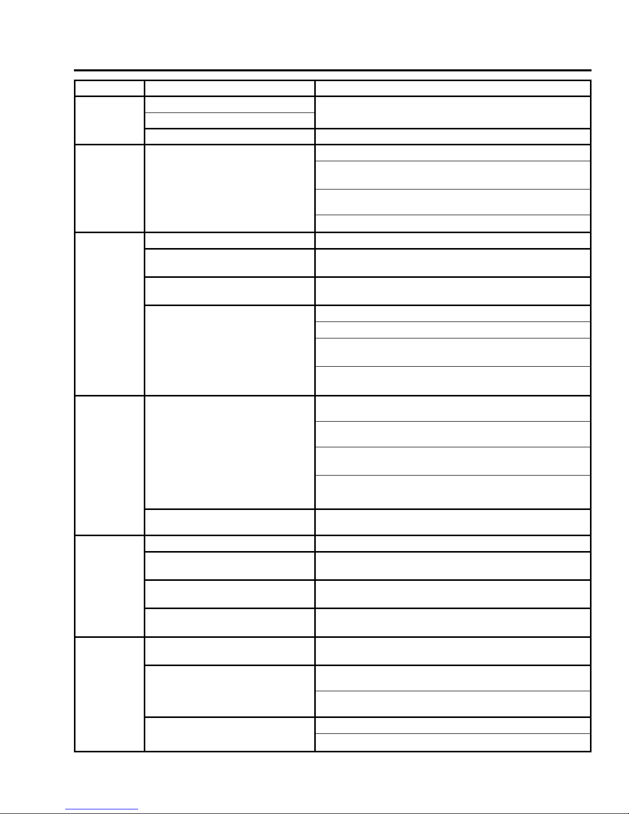
Problem Possible Cause Solution
Thermostat
does not
work
No spark
generation
No pilot
ame ignition
The pilot ame has gone out
The On/Off switch is turn to OFF
The thermostat is set too high
Spark developes near the pilot
assembly or could occur onboard
No spark from the igniter
Air in the gas line
Pilot gas pressure dropout upon
main burner gas valve opening
No gas ow out of the pilot burner
· Turn it ON
· Set the thermostat to a lower temperature
· Check pilot assembly wiring
· Check for broken or poor connection from the sparker to the
electrode
· Check for the spark shorting or arcing at other locations
· Check for defective sparker and spark electrode
· See “no spark generation”
· It takes a while for all the air to purge out of the pilot before gas
can reach the pilot and ignite
· Check gas mains supply and pressure
· Check gas valve wirings and connections to the board
· Check the pilot burner for obstruction
· Check the wirings and connections between the pilot assembly and
the board
· Check the correct gas type settings on the valve and pilot burner
assembly orice
Pilot will not
remain lit
Remote
control does
not work
No reaction
to command
Problem with Flame Sensor circuit
Restrictor setting
The pilot light has gone out
The remote is too far away from
the heater
The remote control receiver is
turned “OFF”
One of the two remote control or
receiver batteries are dead
Receiver or transmitter batteries
are low
A maximum number of failed
ignitions or ame restorations have
been reached.
· Check for proper connection of the Flame Sensor to the DFC board
· Check pilot for full ame impingement around Flame Sensor
· If ame is too small, check gas pressure, adjust pilot rate screw,
check pilot head for damage
· Ensure the ground wire is properly attached to the pilot mounting
bracket and that it is makes a good electrical connection.
· Use the correct restrictor setting for the venting conguration
· See “Pilot will not remain lit”
· Use the remote closer to the heater
· Check the remote control instructions
· Replace the batteries
· Replace the batteries
· Remove any possible blocking conditions. See “locking conditions”
· See how to reset the board from Lockout
No communication between the
remote control and the receiver
· Reprogram the transmitter to the receiver.
· Follow the initializing system for the rst time
47
Page 48
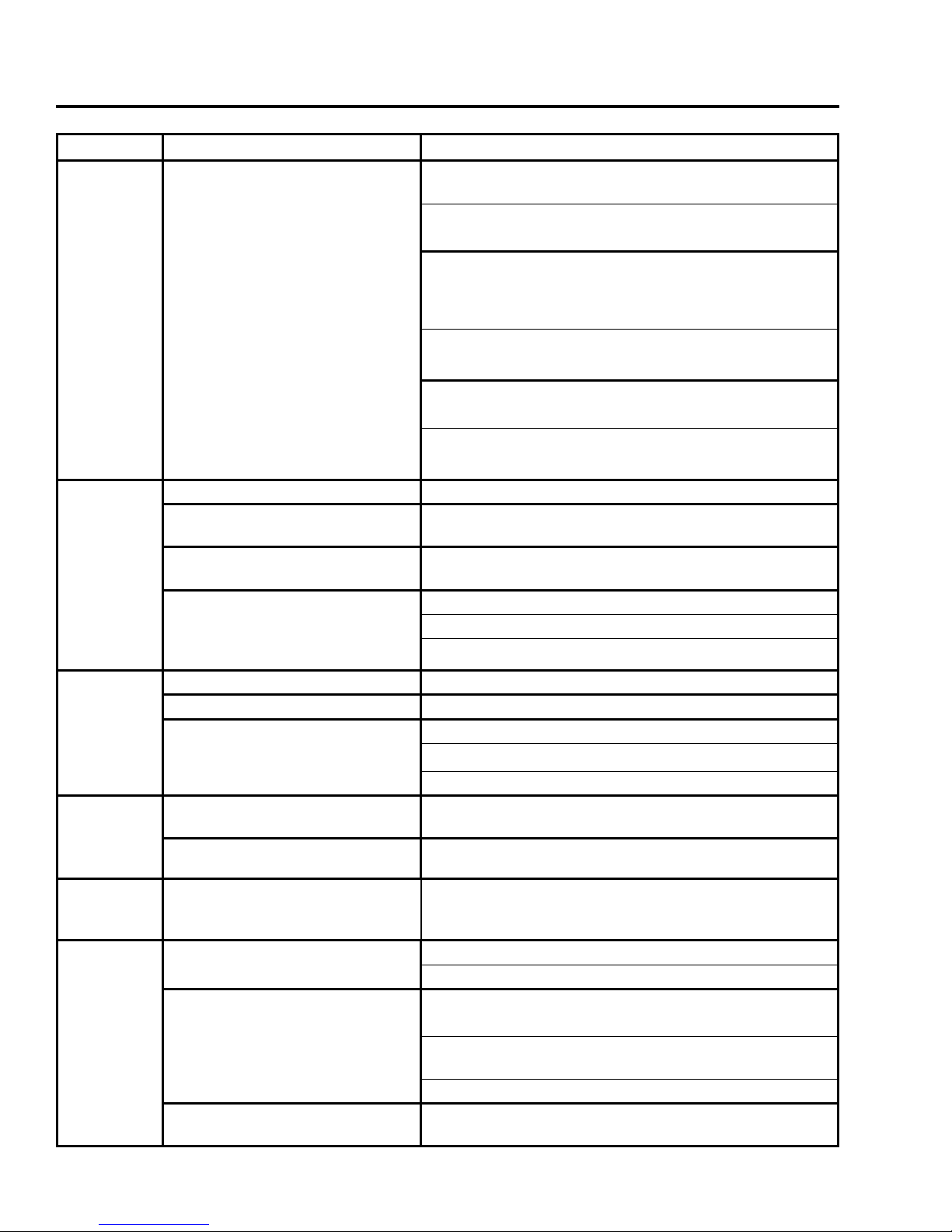
troubleSHooting
Problem Possible Cause Solution
· Turn the system off by pressing the ON/OFF button on
the transmitter
· After approximately 2 seconds press the ON/OFF button
on the transmitter again.
· In the manual ame control mode, use the down arrow
button to reduce the ame to off, indicated by the word
Locking
conditions
Main burners
will not start
Reset the Proame DFC board
The pilot ame has gone out · See “Pilot will not remain lit”
The remote control is not working
correctly
The thermostat is disconnected or
set too high
Problem with thermopile circuit
OFF displayed on the transmitter LCD screen.
· Wait approximately 2 seconds and press the up arrow
button, the ignition sequence will start.
· With the transmitter off, move the slider switch on the
receiver to the OFF position.
· Wait approximately 2 seconds and move the receiver
slider switch to the ON position.
· Replace the batteries
· Set the thermostat to a lower temperature
· Check gas line pressure
· Check wiring to thermostat for breaks
· Check for ame impingement on thermopile
Flame lifting
Blue Flames
Glass fogs up
Flames are
burning
“dirty” or
sooting
Leak in vent pipe · Check for leaks in vent connections
Improper vent conguration
Terminal may be re-circulating ue
gases
The heater has just been started
Improper air shutter adjustment · Adjust air shutter – contact your dealer
Normal condition: after the
appliance warms up the glass will
be clear.
The logs or glasses are placed
incorrectly
Improper air shutter adjustment
Incorrect rating input
· Check vent conguration with manual
· Check to see if terminal is on correctly
· May need to install high wind termination cap.
· Contact dealer
· Normal during start up: ame will yellow as the replace
heats up
**Due to additives in gas, glass may get hazy during
operation** Clean as needed.
· Check log positioning
· Check level of glasses layout
· Increase primary air by opening the air shutter and/or
by opening the vent restrictor
· Check for proper venting and blockage of the vent
termination
· See also “Burners will not remain lit”
· Check manifold pressure and clock input rating for overring
48
Page 49
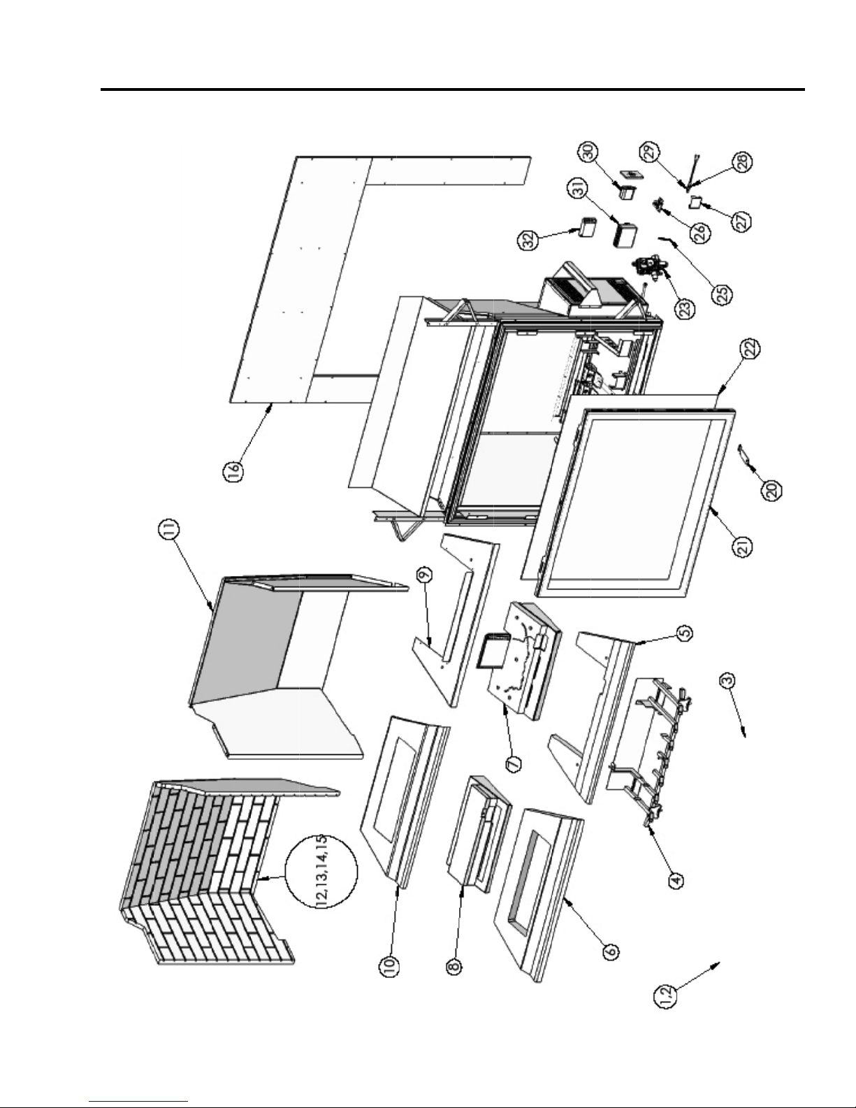
PartS diagram
49
Page 50

PartS diagram - oPtionS
50
Page 51
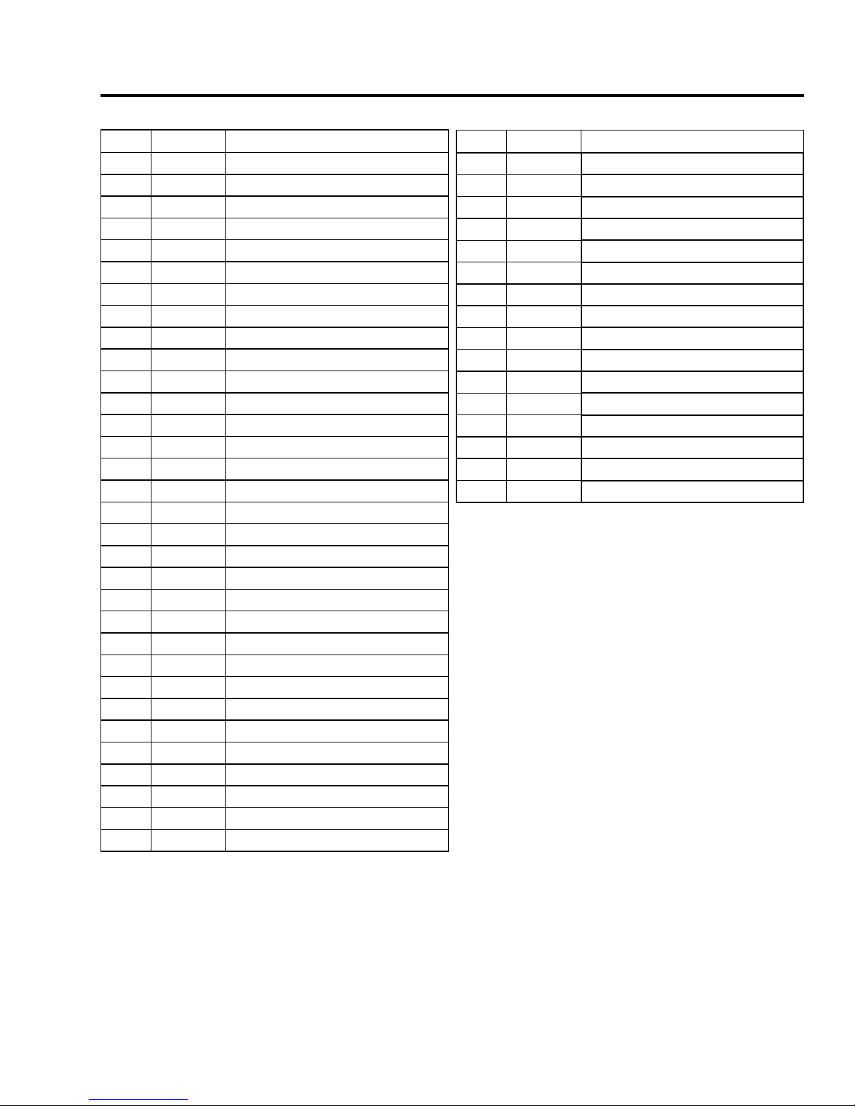
PartS liSt
Item Number Items
1 50-1980
2 50-1984
3 50-2234
4 50-2233
5 50-2235
6 50-2238
7 50-2232
8 50-2231
9 50-2236
10 50-2237
11 50-2239
12 50-2240
13 50-2241
14 50-2242
15 50-2243
16 50-2315
17 50-2006
18 50-2008
19 50-2009
20 50-2001
21 50-2311
22
23 50-2314
24 50-1939
25
26 50-2010
27 50-2319
28 50-2316
29 50-2309
30 50-2007
31 50-2031
32 50-2005
Crushed Glas - White
Crushed Glas - Black
Log Set
Log Grate
Log Burner Accent - Mortar Grey
Glass Burner Accent - Castle Stone
Burner Log / Ember Bed
Burner Glass Media
Log Burner Accent - Black Porcelain
Glass Burner Accent - Black Porcelain
Panel Set - Black Porcelain
Panel Set - Rustic Brick Brown
Panel Set - Rustic Brick Red
Panel Set - Fractured Slate
Panel Set - Castle Stone
Fireplace Facing Kit
Remote Control Transmitter
Wire Harness - Receiver
Wire Harness - IPI
Door Tool
Door Assembly
Glass Door
Valve Assembly (50-2004)
Rock Accents
Wire Loom Gasket
Pilot Assembly
Light Bulb Cover
Halogen Socket Light & Wire
Light Bulbs (Set 2)
Remote Receiver
Fan Control Module (50-1572)
Digital Fireplace Controller
Item Number Items
50-2245
50-2246
50-1970
50-2305
50-2308
50-2312
50-2313
EC-019
EC-011
30-043
50-1983
50-1984
50-5317
50-2320
20-034
50-2310
Fireplace Door Front - AC
Fireplace Door Front - Black
Power Vent Kit
Vent Reducer 6” x 8 5/8” to 5” x 8”
Log Burner Kit
Owners Manual
Technical Manual
Pilot Orice (Injector) NG Threaded
Spark Electrode with Ignitor Cable
SIT Pilot 1/8” Tube w/End Frerules
Pilot Flame Sensor (Long Ceramic)
Pilot Bypass Swith Assembly
Light Circuit Wire Harness
Dual Bulb Door Gasket (20 ft)
Halogen Cycle (Pin Socket)
Valve Access Panel Gasket
51
Page 52

Warranty
Sherwood Industries Ltd. is the manufacturer of the Westgate line of heating products. At Sherwood Industries, our
commitment to the highest level of quality and customer service is the most important thing we do. Each Westgate stove is
built on a tradition of using only the nest materials and is backed by our Exclusive Lifetime Limited Warranty to the original
purchaser. With Westgate, you’re not just buying a replace or stove, you’re buying a company with years of unequalled
performance and quality.
Limited Lifetime Warranty:
Under this warranty, Sherwood Industries Ltd. covers the replace or stove body and accessories against defects in materials
and workmanship, for part repair or replacement for the rst seven (7) years and limited labour for the rst two (2) years to
the original purchaser. This Warranty covers: Firebox, Heat Exchanger, Steel Firebox Panels, Ceramic Logs & Panels, Burner,
Ceramic Glass, Pedestals, Panels and Legs. Please see the exclusions and limitation section below as certain restrictions and
exclusions apply to this warranty.
Limited Two (2) Year Warranty:
Under this warranty, Sherwood Industries Ltd. covers: Gas Assembly, Blower, Blower control, Temperature Sensors and Wire
Harness against defects in materials and workmanship, for part repair or replacement for the rst two (2) years and limited
labour for the rst two (2) years to the original purchaser. Please see the exclusions and limitation section below as certain
restrictions and exclusions apply to this warranty.
Limited One (1) Year Warranty:
Under this warranty, Sherwood Industries Ltd. covers all exterior surface nishes against defects in materials and
workmanship, for part repair or replacement and limited labour for the rst (1) year to the original purchaser. Please see the
exclusions and limitations section below as certain restrictions and exclusions apply to this warranty.
Here is how our Warranty works
If you have any concerns with your Westgate product, please contact the dealer where you purchased the replace or stove.
Your dealer shall make all claims under this warranty in writing.
To the Dealer
When lling out a warranty claim, please complete the following information on an ofcial warranty claim form:
Customer information: Name, address and telephone number of purchaser and date of purchase.
Dealer information: Date of installation, name of installer and dealer, serial number of the appliance, nature of complaint,
defects or malfunction, description and part numbers of any parts replaced.
To the Distributor
Sign and verify that work and information are correct.
Exclusions and Limitations:
1. This Warranty does not cover tarnish, discoloration or wear on the plating or paint.
2. This Warranty excludes wear and tear or breakage caused by cleaning, moving or service on log set and panels.
3. A qualied installer must install this stove or replace. This Limited Warranty covers defects in materials and workmanship
only if the product has been installed in accordance with local building and re codes; in their absence, refer to the
owner’s manual. If the product is damaged or broken as a result of any alteration, willful abuse, mishandling, accident,
neglect, or misuse of the product, the Limited Warranty does not apply.
4. The stove must be operated and maintained at all times in accordance with the instructions in the Owner’s Manual. If the
unit shows signs of neglect or misuse, it is not covered under the terms of this Warranty policy. Performance problems
due to operator error will not be covered by the Limited Warranty policy.
5. As this is a heating appliance, some changes in colour of surface nishes may occur. This is not a aw and as such is not
covered under this warranty.
6. Some minor expansion, contraction, or movement of certain parts and resulting noise, is normal and not a defect and,
therefore, is not covered under this Limited Warranty.
7. Misuse includes over-ring. Over-ring this appliance can cause serious damage and will nullify the Limited Warranty.
8. The Limited Warranty will cover glass thermal breakage only and will not cover misuse of the stove glass, including but not
limited to glass that is struck, has surface contaminates or has had harsh or abrasive cleaners used on it.
9. This warranty does not cover products made or provided by other manufacturers and used in conjunction with the
operation of this stove without prior authorization from Sherwood Industries Ltd. The use of such products may nullify
the Limited Warranty on this stove. If unsure as to the extent of this Limited Warranty, contact your authorized Westgate
dealer before installation.
10. Sherwood Industries Ltd. will not be responsible for inadequate performance caused by environmental conditions.
11. The Limited Warranty does not cover installation and operational related problems caused by downdrafts or spillage
caused by environmental conditions. Environmental conditions include but are not limited to nearby trees, buildings,
roof tops, wind, hills, mountains, inadequate venting or ventilation, excessive offsets, negative air pressures or other
inuences caused by mechanical systems such as furnaces, fans, clothes dryers etc.
52
Page 53

Warranty
12. The Limited Warranty is void if:
a) The stove has been operated in atmospheres contaminated by chlorine, uorine or other damaging chemicals.
b) The stove is subject to submersion in water or prolonged periods of dampness or condensation.
c) Any damage to the unit, combustion chamber or other components due to water, or weather damage which is the
result of, but not limited to, improper chimney/venting installation.
c) Salt air in coastal areas or high humidity can be corrosive to the nish; these environments can cause rusting.
Damage caused by salt air or high humidity is not covered by the Limited Warranty.
13. Exclusions to the Limited Warranty include: injury, loss of use, damage, failure to function due to accident, negligence,
misuse, improper installation, alteration or adjustment of the manufacturer’s settings of components, lack of proper and
regular maintenance, alteration, or act of God.
14. The Limited Warranty does not cover damage caused to the replace or stove while in transit. If this occurs, do not
operate the stove and contact your courier and/or dealer.
15. Limited Warranty does not extend to or include rebox paint, door or glass gaskets with damage caused by normal wear
and tear, or exterior paint discoloration or chipping, worn gaskets, etc.
16. The Limited Warranty does not include damage to the unit caused by abuse, improper installation, or modication of the
unit.
17. Damage to plated surfaces caused by ngerprints, scratches, melted items, or other external scores and residues left on
the plated surfaces from the use of abrasive cleaners or polishes is not covered in this warranty.
18. The Limited Warranty does not cover tarnish, discoloration or wear on the plated surfaces.
19. The paint on the Metal Brick Liner may peel. This is due to the extreme conditions applied to the paint during normal
usage. It is not a aw and is not covered under warranty.
20. Sherwood Industries Ltd. is free of liability for any damages caused by the replace or stove, as well as inconvenience
expenses and materials. The Limited Warranty does not cover incidental or consequential damages.
21. The Limited Warranty does not cover any loss or damage incurred by the use or removal of any component or apparatus
to or from the Westgate replace or stove without the express written permission of Sherwood Industries Ltd. and
bearing a Sherwood Industries Ltd. label of approval.
22. Any statement or representation of Westgate products and their performance contained in Westgate advertising,
packaging literature, or printed material is not part of the Limited Warranty.
23. The Limited Warranty is automatically voided if the replace or stove’s serial number has been removed or altered in any
way. If the stove is used for commercial purposes, it is excluded from the Limited Warranty.
24. No dealer, distributor, or similar person has the authority to represent or warrant Westgate products beyond the
terms contained within the Limited Warranty. Sherwood Industries Ltd. assumes no liability for such warranties or
representations.
25. Sherwood Industries Ltd. will not cover the cost of the removal or re-installation of the stove, hearth, facing, mantels,
venting or other components.
26. Labour to replace or repair items under this Limited Warranty will be covered per our warranty service fee reimbursement
schedule. Labour rates are set per component and as such total labour costs may not be covered.
27. Sherwood Industries Ltd. is not liable for freight or labour on any stove replaced in-eld and is not liable for travel costs
for service work. In the event of in-home repair work, the customer will pay any in-home travel fees or service charges
required by the Authorized Dealer.
28. At no time will Sherwood Industries Ltd. be liable for any consequential damages which exceed the purchase price of the
unit. Sherwood Industries Ltd. has no obligation to enhance or modify any stove once manufactured (example: as a
stove evolves, eld modications or upgrades will not be performed).
29. This Limited Warranty is applicable only to the original purchaser and it is non-transferable.
30. This warranty only covers Westgate products that are purchased through an authorized Westgate dealer.
31. If for any reason any section of the Limited Warranty is declared invalid, the balance of the warranty remains in effect
and all other clauses shall remain in effect.
32. The Limited Warranty is the only warranty supplied by Sherwood Industries Ltd., the manufacturer of the stove. All other
warranties, whether expressed or implied, are hereby expressly disclaimed and purchaser’s recourse is expressly limited
to the Limited Warranty.
33. Sherwood Industries Ltd. and its employees or representatives will not assume any damages, either directly or indirectly,
caused by improper usage, operation, installation, servicing or maintenance of this stove.
34. Sherwood Industries Ltd. reserves the right to make changes without notice. Please complete and mail the warranty
registration card and have the installer ll in the installation data sheet in the back of the manual for warranty and
future reference.
35. Sherwood Industries Ltd. is responsible for stocking parts for a maximum of seven (7) years after discontinuing the
manufacture or incorporation of the item into its products. An exception to this would be if an OEM supplier is not
to supply a part.
able
53
Page 54

inStallation data SHeet
The following information must be recorded by the installer for warranty purposes and future reference.
NAME OF OWNER:
_________________________________________
ADDRESS:
_________________________________________
_________________________________________
_________________________________________
PHONE:___________________________________
MODEL:___________________________________
SERIAL NUMBER:___________________________
DATE OF PURCHASE: _____________ (dd/mm/yyyy)
NAME OF DEALER:
_________________________________________
ADDRESS:
_________________________________________
_________________________________________
_________________________________________
PHONE:___________________________________
NAME OF INSTALLER:
_________________________________________
DATE OF INSTALLATION:___________(dd/mm/yyyy)
� NATURAL GAS (NAT) � PROPANE(LPG)
INLET GAS PRESSURE:_________in wc
MAIN BURNER ORIFICE:__________# DMS
PILOT ORIFICE #_________OR________in diam.
INSTALLER’S SIGNATURE:
_________________________________________
MANUFACTURED BY:
SHERWOOD INDUSTRIES LTD.
6782 OLDFIELD RD. SAANICHTON, BC, CANADA V8M 2A3
July 01 2010
www.westgatereplaces.com
ADDRESS:
_________________________________________
_________________________________________
_________________________________________
PHONE:___________________________________
C-12283
54
 Loading...