

Page 1
Telematic
Application Note
TAN 1005
Surge Suppression
for Zone 0 Locations
991.115
03/99
Synopsis
This note discusses the surge
protection requirements of
intrinsically safe circuits entering a
Zone 0 hazardous area. It
analyses the potential gradients
generated by lightning strikes and
their possible routes of invasion.
The alleviation of the problem at
the zone 0 interface transfers the
problem elsewhere and an
adequately safe pragmatic
solution is proposed.
A member of The MTL
Instruments Group plc
Page 2

CONTENTS
PAGE
1 INTRODUCTION ........................................................................................................................... 1
2 INTRINSIC SAFETY REQUIREMENTS FOR EARTHING AND BONDING............................................... 2
3 CERTIFICATION OF SURGE SUPPRESSORS ...................................................................................... 2
4 PROTECTION OF THE SENSOR AND TRANSMITTER ........................................................................ 3
5 PROTECTION OF THE GALVANIC ISOLATOR AND SAFE-AREA EQUIPMENT....................................... 3
6 PROTECTION OF SUPPLIES AND SIGNALS FROM EXTERNAL SOURCES ............................................ 4
7 CONCLUSION ............................................................................................................................. 5
APPENDIX A .......................................................................................................................................... 5
APPENDIX B........................................................................................................................................... 5
Application Notes from Telematic
Telematic publish an increasing number of Application Notes providing easily understood information on various aspects of surge and
lightning protection. At the date of publication of this Application Note, the list included:–
TAN1001
TAN1002
TAN1003
TAN1004
TAN1005
TAN1006
TAN1007
Lightning surge protection for electronic equipment – a practical guide
A relatively brief and easy to understand introduction to the subject – an excellent starting point
Lightning and surge protection – basic principles
A more detailed account of the mechanism of lightning strikes and the measures needed to achieve an adequate level
of protection
Earthing guide for surge protection
A detailed analysis of the subject of earthing for surge suppression purposes, this is both an easily understood
exposition and a valuable reference document
Surge protection for intrinsically safe systems
A description of the best methods of combining surge suppression and intrinsically safe systems
Surge suppression for Zone 0 locations
A detailed analysis of this particular aspect of surge suppression in hazardous areas; complements TAN1004
Surge protection for weighing systems
Discusses, in some detail, the specific application of surge suppression to load-cell weighing systems
Surge protection for Local Area Networks
Discusses ways in which Local Area Networks can be damaged by lightning induced transients and how they can be
protected economically
About Telematic
Telematic Limited is a company with a well-established reputation for the design and manufacture of surge protection devices and with
considerable experience of successful installation practices. A consultancy service is available to advise customers on the selection and
location of devices for particular applications. If you have any specific enquiries, please contact Telematic directly at the address on the
back cover or contact your local MTL group company – whichever is most convenient.
Telematic is a member of the MTL Instruments group and is therefore in a unique position to make good use of Measurement Technology’s
leading position as a supplier of intrinsically safe interfaces to provide the best possible choices of equipment for hazardous-area applications.
The principal author of this publication is LC Towle, BSc, Chairman at Telematic Ltd, who acknowledges with thanks the comments of
colleagues and customers. If you have any comments (preferably constructive) on this document, please make them to the author so that the
document can be amended and made even more useful.
Page 3
SURGE SUPPRESSION FOR
ZONE 0 LOCATIONS
1 INTRODUCTION
For many years there has been general recognition that there is a
significant problem from lightning strikes on installations such as storage tanks. The codes of practice for instrumentation in hazardous areas for Germany and Holland both contain recommendations for specific installation practice. In the United Kingdom the code of practice
contains no detailed requirements and the problem has always been
approached on an individual installation basis. Perhaps the clearest
references are in the draft revision of the IEC code which contains two
specific references to lightning problems. These, together with the relevant clause on potential equalisation, are quoted in full as an appendix (clauses 6.3, 6.5 and 12.3).
Although this code of practice has not yet been finally voted on and
published it is likely to form the basis of accepted practice in significant parts of the world and forms a convenient reference document.
When a plant is struck by lightning then the point of impact would
inevitably ignite a gas and air mixture that was present. Ignition at
points other than the point of impact are dependent on the efficiency of
bonding which must be adequate to prevent side flashes and hence
bonding should have a low impedance as well as a low resistance.
The majority of petrochemical installations are adequately bonded and
sufficiently robust to prevent excessive lightning damage although some
side flashes usually occur following a significant adjacent strike. Corona discharge from structures does occur in some atmospheric conditions and multiple streamers rising from structures to meet the usual
lightning downward leader (which selects one of them) are a well established phenomenon. It is possible that if either a lightning flash, an
upward corona streamer, or a side flash pass through a flammable
mixture of gas then ignition will occur. In general, conventional bonding of a plant is considered adequate and the implications of possible
lightning impact points are not considered a significant problem except in the case of vents which frequently discharge. Where lightning
can damage the electrical insulation of power circuits there is a transient potential hazard caused by the follow through of the power circuit. This should however be rapidly removed by the electrical protection ie. fuses, out of balance circuit breakers etc. which is a fundamen-
tal requirement of all the methods of protection used for power equipment. It is not usual for lightning induced current to directly cause enough
heating to create a hazard by temperature ignition, since the current
pulses are too short to create a sustained high temperature. However,
vapourisation of flimsy conductors such as printed circuit tracks is not
unusual. Overheating may occur if there is a power follow through of
a fault initiated by the lightning induced voltage. It can be argued that
if intrinsically safe apparatus is likely to be subjected to lightning damage then it is necessary to protect it since, following the lightning damage, its intrinsic safety may be impaired. There is no requirement in the
apparatus standard to consider the effect of excessive surges, which
are difficult to predict and could lead to damage. The problem should
not be exaggerated, since lightning damage usually results in failure
to a safe condition and also to operational failure and hence should
be noticed and corrected. Possibly the need to repair or remove nonfunctional electrical equipment needs to be given further emphasis in
the code of practice.
It is accepted that transient hazards during infrequent electrical faults
can occur in Zones 1 and 2 providing that they are removed as quickly
as is practical. The argument being that the coincidence of the potentially hazardous electrical fault and a flammable mixture of gas is sufficiently improbable to be acceptable. In the particular case of lightning a similar analysis suggests that transient hazards caused by points
of lightning impact and the occasional failure to bond adequately are
possibly acceptable in Zone 1 and 2 but not acceptable in Zone 0.
Fortunately the majority of Zone 0 locations are contained within process vessels which form an adequate Faraday cage which effectively
prevents significant potential differences within the Zone 0 and hence
the problem is generally controllable. Where problems are known to
exist then special precautions are taken, for example the bond between the floating roof of a storage tank and the tank itself is designed
with considerable care, and subjected to frequent inspections. A problem is introduced when the Faraday cage of the Zone 0 is broken by
the introduction of equipment for measurement purposes.
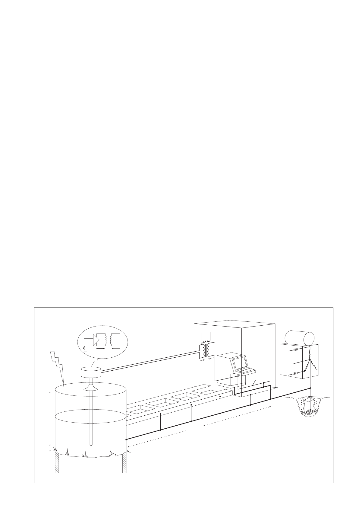
Figure 1 shows an average contents temperature gauge being used in
a storage tank and this illustrates the problem. The potential equalising
network is shown diagramatically as a substantial structure interconnected electrically, in practice it is the plant structure bonded together.
The transmitter protruding from the tank top is intended to illustrate the
concept. In practice in a high lightning activity area it would be unwise
to have the equipment protruding from the tank in this way since it
would possibly invite a direct strike and could be the natural source of
corona discharge. It should be provided with some mechanical protec-
100kA
10µS
10m
0.1µH/m
(10kV)
30KV
L
1
L
2
Potential equalising
network
30kV
Computer 0V
Power 0V
0.1µH/m
10kA
500m
(50kV)
Figure 1 Installation without surge protection
1
Page 4

tion from this possibility or sited with care in the shelter of some other
protrusion. The diagram shows a two wire 4 to 20 milliamp transmitter
with internal isolation fed from a galvanic isolator. To establish the
order of the problem some assumptions are made which cannot be
fully justified but are believed to be reasonable. These are:
a) The tank has an inductance of 0.1µH/metre and is 10 metres high
before reaching the equipotential plane of the plant.
b) The potential equalisation system has a similar low inductance of
0.1µH/metre and the tank is situated some 500 metres from the
control room.
c) Lightning strikes the tank, and the strike is 100kA rising linearly in
10 microseconds. Some 10kA is assumed to flow through the potential equalising bond to the control room distribution centre transformer.
When the apparatus standard was being written the question of the
quality of the insulation of the circuit from earth was discussed. It was
decided that except where the intrinsic safety was critically dependent
e.g. where a current limiting resistor could be short circuited, then the
creepage and clearance requirements should be waived but that the
measure of insulation adequacy was a 500 volt insulation test. This
has led to occasional problems e.g. strain gauges, but in general has
not caused problems. It was not thought that circuits would be subjected to 500 volts in the hazardous areas, if they are, then they are no
longer intrinsically safe. [Note - Using 20 microjoules as the ignition
energy of hydrogen, the permissible capacitance associated with 707
volts is 80 picofarads and the safe voltage corresponding to the permitted 10 nanofarads is 63 volts]. The subsequent analysis therefore
ignores the 500 volt insulation test requirement and concentrates on
producing a solution which reduces the voltages applied to the Zone 0
in transient conditions to an acceptably safe level.
With these assumptions the transient peak volts across the tank is 10kV
and the voltage across the potential equalising network is 50kV. The
resultant 60kV potential difference would be divided across the isolation within the interface and the isolation within the transmitter with a
high probability that both would break down.
This example is used to illustrate the remainder of this document. In
practice all specific installations will differ in detail from this example
but the general principles are illustrated by this analysis. Usually a
document of conformity for the intrinsically safe system in accordance
with EN50039 should be generated for the specific system. The combination of MTL Instruments Ltd and Telematic Ltd is particularly suited
to giving assistance in creating such documentation, should help be
required.
2 INTRINSIC SAFETY REQUIREMENTS
FOR EARTHING AND BONDING
Usually instrumentation introduced into a Zone 0 is intrinsically-safe to
the ia requirements and is nearly always ia IIC T4 certified by some
appropriate organisation. If this simplifying assumption is made then
certain aspects of intrinsic safety practice need to be examined with
this application in mind.
In the IEC draft code of practice a strong preference for using galvanically isolated interfaces for Zone 0 is expressed. The arguments for
galvanic isolation have always been strongly advocated within Germany and France and are based on the assumption that galvanically
isolated circuits are less susceptible to earth faults and potential differences between earths than shunt-diode safety barriers. There are literally millions of circuits using shunt-diode safety barriers and although
there have been a number of operational problems, there is no indication that any safety problem has arisen from their use and hence probably the arguments are theoretically correct but may not be practically
significant. However the economic difference between shunt-diode safety
barriers and isolators is not significant in this type of installation and if
necessary high accuracy transfer can usually be achieved using digital signals. Although an acceptable solution using shunt-diode safety
barriers can be achieved, this analysis proceeds on the assumption
that isolated interfaces will be used if only to avoid the distraction of
any argument resulting from the use of shunt-diode safety barriers.
It is usual to require that intrinsically safe circuits are fully floating or
earthed at one point only. The reason for this requirement is to prevent
significant circulating currents flowing within the circuit due to potential differences within the plant. The problem is not so much that there
is a significant safety risk but that it is difficult to certify a system with
unspecified currents. In practice the safety analysis carried out with
multiple earth faults is based on the assumption that all earths are at
the same potential and interconnected by zero impedance. Since the
single earth philosophy is largely compatible with the low frequency
interference avoidance practices in instrumentation this has not been
challenged until recently. The increased awareness arising from the
EMC directive of the effects of high frequency interference has led to
the greater use of decoupling capacitors on input circuits which are a
form of multiple earthing. This is recognised in both the apparatus
standard and the code of practice, the latter permitting a total capacitance of 10nF in any one circuit.
2
3 CERTIFICATION OF SURGE SUPPRESSORS
Usually, surge suppressor circuits can be classified as “simple apparatus” using any of the available definitions. Fortunately the requirements
of simple apparatus have been more clearly defined in the second
edition of EN50020 (reproduced in Appendix 2) and hence due allowance for the small inductors sometimes used can now be made.
It is normal practice to have “simple apparatus” certified by an appropriate body such as BASEEFA if they are frequently used in intrinsically
safe circuits. Although not strictly essential such third party certification
gives additional comfort to the end user and makes the marketing of
the product easier. It is important however to recognise that the certification relates only to the effect the surge suppression device has on the
intrinsic safety of the circuit when the circuit is not affected by lightning
transients. There are no requirements in the apparatus standards relating to the performance of surge suppressors. Although BASEEFA do
satisfy themselves that the product they are certifying is not useless they
are not responsible for its performance during a transient surge, nor is
anyone able to claim that the circuit is intrinsically safe during the brief
time it is affected by the lightning surge. The full implications of the
recent “ATEX” directive with respect to surge suppressors has not yet
been pursued, but may lead to some additional testing requirements.
TP48
–
+
300V
2µS
60V
Instrument
housing
Figure 2 Surge suppresion of the transmitter
60V
60V
L
1
L
2
60V
Tank shell
Page 5

60V
TP48
Bonding strap
10kV
4 PROTECTION OF THE SENSOR AND
TRANSMITTER
The problem of surge protection of the transmitter and sensor is relatively easy to solve since it is only necessary to prevent significant
voltage differences so as to avoid ignition capable sparks. This can be
achieved by using a combination of surge limiting devices, which effectively control the voltage between the signal wires and with respect
to the adjacent structure.
A practical solution to this problem is to use a Telematic TP48 (see
figure 2) which contains the necessary parallel surge components in
an encapsulated block within a stainless steel hexagon bar which can
be screwed into the unused cable entry of the transmitter. To achieve
suppression against the expected transients it is necessary to use a
combination of gas discharge tubes and solid state devices. With the
usual test waveform this combination restricts the transient voltage between the circuit and structure to 300 volts which then falls to 60V after
two microseconds and the voltage between the signal lines to 60V. It is
a matter of some debate as to what transient voltages would be anticipated on a practical installation with protection but they would not
exceed 150V and almost certainly would be considerably less.
To be effective the surge suppressor must be adequately bonded to the
structure. Almost all transmitters contained within metallic enclosures
have both internal and external bonding connections which can be
utilised to ensure adequate bonding. The need for the external bond is
reduced if the mounting of the transmitters ensures an effective bond.
but if there is any doubt a substantial bond should be used. The size of
the bond is largely determined by the need to be mechanically robust.
A flat short braid with suitable tags has much to commend it.
This suppression circuit produces in the worst case condition a short
150V pulse across the transmitter isolation and a longer 60V pulse,
both of which the isolation will normally reject. Any small transient
which is fed by the transformer capacitance to the sensor circuit would
be absorbed by the high frequency input filter capacitors of the sensor
input circuit.
The results of fitting surge suppression on the transmitter therefore ensures that there is an adequate level of protection for the sensor and
transmitter. However removing the potential difference from the transmitter transfers the whole of the potential difference to the isolator as
illustrated in Figure 3. Typically an intrinsically safe isolator will withstand an occasional 5kV transient (the components are routinely tested
60kV
50kV
Figure 3 System with transmitter only protected
at 1.5kV rms) but damage would be expected at 60kV. The usual result
of this failure would be damage to the computer interface which would
have both cost and operational safety implications. In non hazardous
locations it is not unusual for the loss of individual transmitters to be
accepted as sacrificial but to protect the computer interface so that the
possibility of more complex interacting faults is reduced, and the possibility of the total system being shut down is removed.
The suppressor discussed has a BASEEFA certificate which permits its
use in conventional intrinsically safe circuits [it is also Ex d certified].
The level of protection offered has been carefully chosen so that all
known two wire transmitters can be adequately protected. The leakage currents associated with shunt protection devices are controlled so
that they do not significantly affect the operational accuracy of the loop.
5 PROTECTION OF THE GALVANIC
ISOLATOR AND SAFE-AREA EQUIPMENT
The use of surge suppression between the isolator and the computer
input interface protects the computer interface and the isolators are
then sacrificial. The unspecified damage to the isolators is not however
desirable and the better installation is to protect the isolators on the
hazardous area side as indicated in figure 4.
The standard solution to this problem is to use the SD32X which would
reduce the voltages applied to the isolator to the acceptable levels as
indicated and would not significantly affect the operation of the circuit.
[Note. There is a version of the suppressor which has a replaceable
fuse and isolation link. In this application the fuse it not likely to be
blown hence this alternative should only be used if the isolation link is
thought to be useful].
The SD series has not yet been certified by BASEEFA as being suitable
for connection into intrinsically safe circuits although an application
has been made and hence its acceptability is based on it being simple
apparatus as defined in the second edition of EN50020 [see Appendix B]. It does contain two small inductors which have a combined
inductance of 200 microhenries. However the conventional transmitter
circuit is powered from a 28 volt 300 ohm source which has permitted
cable parameters of 0.13 microfarads and 4.2 millihenries. The permitted length of cable is usually restricted to approximately 600 metres
by the capacitance requirement and hence a marginal reduction of the
permitted inductance to 4 millihenries (equivalent to 4Km) has no effect.
3
Page 6

1kA (10µS)
15m
15µH
1.5kV
Figure 4 Intrinsically safe circuit fully protected
The system should be designed so that when the surge current is diverted the voltage drop across the bonding conductor does not create
a large voltage across the isolator. Figure 4 gives an illustration of a
satisfactory system. With the currents and distances indicated the isolator is still subjected to a 1.5kV pulse and hence the importance of
keeping the interconnection as short as possible cannot be over emphasised.
The use of a second suppressor on the circuit means that the intrinsically safe system is now indirectly bonded at two points. The sequence
in which the suppressors begin to conduct is quite complex since it
does depend on how the potential difference between the two earths
develops. The sustained situation which is the least desirable is that the
transmitter protector requires 60 volts to conduct and the computer
protector 30 volts to conduct. Hence there would need to be at least
90 volts between the two earths before a significant current could flow
within the intrinsically safe circuit. During this short time the circuit is
not intrinsically safe but the equipment at either end of the line is operating within its rating. Any hazard which does exist is in the cable and
is in the Zone 1, or Zone 2 location. It is a smaller hazard than that
which would exist without the protection and hence is a desirable acceptable solution.
6 PROTECTION OF SUPPLIES AND
SIGNALS FROM EXTERNAL SOURCES
If the mains supply to the system is subject to lightning surges then the
operational integrity and safety of the system can be adversely affected. An obvious invasion route for the intrinsically safe system is via
the isolator supply which is derived either directly or indirectly from the
supply. The intrinsic safety certification process assumes that the power
Signal Suppressor
Mains supply
Data link
Mains Filter
suppressor
Figure 5 Adequately protected system
4
Page 7

supply will contain a significant amount of surges but if for any reason
the supply is particularly exposed to invasion from lightning induced
surges then some consideration to suppressing the main supply should
be given.
A practical economic solution is to protect the supply input to the computer system as indicated in figure 5.
A similar argument can be made if a data link is made to any remote
location. This is less likely to directly affect the intrinsically safe circuit
but can be very damaging to the computer.
7 CONCLUSION
The solution shown in figure 5 is therefore the best practical solution to
achieve safety for circuits entering Zone 0 where there is a significant
probability of the circuit being influenced by adjacent lightning strikes.
It is probable that this solution is not directly applicable to all installations but a solution based on a similar analysis is usually achievable.
MTL and Telematic are in an almost unique position to give advice on
this problem and consider that they have the competence to assist in
preparing the relevant documentation.
APPENDIX A
This appendix is comprised of extracts from the draft IEC 79-14 code
of practice of electrical installations in hazardous areas dated October
1994. It may still be modified in detail but it is not probable that the
principles will change.
6.3 Potential equalisation
Potential equalisation is required for installations in hazardous areas.
For TN, TT and IT systems all exposed and extraneous conductive parts
shall be connected to the equipotential bonding system. The bonding
system may include protective conductors, metal conduits, metal cable
sheaths, steel wire armouring and metallic parts of structures, but shall
not include neutral conductors. Connections shall be secure against
self-loosening.
Exposed conductive parts need not be separately connected to the
equipotential bonding system if they are firmly secured to and are in
metallic contact with structural parts or piping which are connected to
the equipotential bonding system. Extraneous conductive parts, which
are not part of the structure or of the electrical installation, need not be
connected to the equipotential bonding system, if there is no danger of
voltage displacement, for example frames of doors or windows.
For additional information see clause 413 of IEC 364-4-41.
In installations with intrinsically-safe circuits for Zone 0 the intrinsicallysafe apparatus and the associated apparatus shall comply with IEC
79-11 category ‘ia’. Associated apparatus with galvanic isolation
between the intrinsically-safe and non-intrinsically-safe circuits is preferred. Associated apparatus without galvanic isolation may be used
provided the earthing arrangements are in accordance with item 2) of
12.2.4 and any mains powered apparatus connected to the safe area
terminals are isolated from the mains by a double wound transformer,
the primary winding of which is protected by an appropriately rated
fuse of adequate breaking capacity. The circuit (including all simple
components, simple electrical apparatus, intrinsically-safe apparatus,
associated apparatus and the maximum allowable electrical parameters of interconnecting cables) shall be of category ‘ia’.
Simple apparatus installed outside the Zone 0 shall be referred to in
the system documentation and shall comply with the requirements on
IEC 79-11, category ‘ia’.
If earthing of the circuit is required for functional reasons the earth
connection shall be made outside the Zone 0 but as close as is reasonably practicable to the Zone 0 apparatus.
If part of an intrinsically-safe circuit is installed in Zone 0 such that
apparatus and the associated equipment are at risk of developing
hazardous potential differences within the Zone 0, for example through
the presence of atmospheric electricity, a surge protection device shall
be installed between each non-earth bonded core of the cable and the
local structure as near as is reasonably practicable, preferably within
1 m, to the entrance to the Zone 0. Examples of such locations are
flammable liquid storage tanks, effluent treatment plant and distillation
columns in petrochemical works. A high risk of potential difference
generation is generally associated with a distributed plant and/or exposed apparatus location, and the risk is not alleviated simply by using underground cables or tank installation.
The surge protection device shall be capable of diverting a minimum
peak discharge current of 10 kA (8/20 µs impulse to IEC 60-1, 10
operations). The connection between the protection device and the
local structure shall have a minimum cross-sectional area equivalent to
4 mm2 copper.
The spark-over voltage of the surge protection device shall be determined by the user and an expert for the specific installation.
NOTE - The use of a surge protection device with a spark-over voltage
below 500 V a.c. 50 Hz may require the intrinsically-safe circuit to be
regarded as being earthed.
The cable between the intrinsically-safe apparatus in Zone 0 and the
surge protection device shall be installed such that it is protected from
lightning.
Metallic enclosures of intrinsically-safe apparatus need not be connected
to the equipotential bonding system, unless required by the apparatus
documentation. Installations with cathodic protection shall not be connected to the equipotential bonding system unless the system is specifically designed for this purpose.
NOTE - Potential equalisation between vehicles and fixed installations
may require special arrangements, for example, where insulated flanges
are used to connect pipelines.
6.5 Lightning protection
In the design of electrical installations, steps shall be taken to reduce
the effects of lightning.
NOTE - In the absence of IEC standards on protection against lightning, national or other standards should be followed.
Subclause 12.3 gives details of lightning protection requirements for
Ex ‘ia’ apparatus installed in Zone 0.
12.3 Installations for Zone 0
Intrinsically-safe circuits shall be installed in accordance with 12.2 except
where modified by the following special requirements.
APPENDIX B
Requirements of simple apparatus extracted from EN50020:1994.
5.4 Simple apparatus
The following apparatus shall be considered to be simple apparatus:
a) passive components, e.g. switches, junction boxes,
potentiometer and simple semiconductor devices.
b) source of stored energy with well defined parameters, e.g.
capacitors or inductors, whose values shall be considered when
determining the overall safety of the system.
c) sources of generated energy, e.g. thermocouples and photo-
cells, which do not generate more than 1,5 V, 100 mA and
25 mW. Any inductance or capacitance present in these sources
of energy shall be considered as in b).
Simple apparatus shall conform to all relevant requirements of this standard but need not be certified and need not comply with clause 12. In
particular the following aspects shall always be considered.
5
Page 8

1) Simple apparatus shall not achieve safety by the inclusion of
Telematic
voltage and/or current limiting and/or suppression devices.
2) Simple apparatus shall not contain any means of increasing
the available voltage or current, e.g. circuits for the generation of ancillary power supplies.
3) Where it is necessary that the simple apparatus maintains the
integrity of the isolation from ‘earth’ of the intrinsically-safe
circuit, it shall be capable of withstanding the test voltage to
earth in accordance with 6.4.12. Its terminals shall conform
to 6.3.1.
4) Non-metallic enclosures and enclosures containing light metals when located in the hazardous area shall conform to 7.3
and 8.1 of EN50014.
5) When simple apparatus is located in the hazardous area it
shall be temperature classified. When used in an intrinsically
safe circuit within their normal rating switches, plugs and sockets and terminals are allocated a T6 temperature classification
for Group II applications and considered as having a maximum surface temperature of 85°C for Group I applications.
Other types of simple apparatus shall be temperature classified in accordance with clause 4 and 6 of this standard.
Where simple apparatus forms part of an apparatus containing other
electrical circuits the whole shall be certified.
The principal author of this application note is L C Towle. BSc CEng. Chairman of Telematic Ltd. All Telematic Application Notes
have significant input from the staff at Telematic and its customers. If you have any comments (preferably constructive) on this document,
please make them to the author so that the document can be amended and made even more useful.
Telematic Limited
Alban Park, Hatfield Road, St Albans, Herts AL4 0XY
Telephone +44 (0)1727 833147 Fax +44 (0)1727 850687
E-mail enquiry@telematic.com Web site http://www.telematic.com
A member of The MTL Instruments Group plc
03/99 Printed in the EU
 Loading...