

Page 1
WTI Part No.: 13051
Rev. B
SRM-100
Secure Rack Modem
User's Guide
5 Sterling · Irvine · California 92618-2517
(949) 586-9950 · Toll Free: 1-800-854-7226
Fax: (949) 583-9514 · http://www.wti.com
Page 2

Table of Contents
1. Introduction
2. Unit Description
2.1. Front Panel
2.2. Back Panel
3. Getting Started
3.1. Applying Power to the Unit
3.2. Connecting a PC to the Console Port
3.3. Communicating with the SRM-100
4. Hardware Installation
4.1. Connecting Power to the SRM-100
4.1.1. AC Powered Units
4.1.2. DC Powered Units
4.2. SetUp Switches
4.2.1. Default Modem Baud Rate (Sw1, Sw2)
4.2.2. Default Flow Control Format (Sw3) .......................4-2
4.2.3. Default Bits and Parity (Sw4) ..........................4-2
4.2.4. Default Rings to Answer (Sw5) .........................4-3
4.2.5. Default ARQ/Compression Status (Sw6) ....................4-3
4.2.6. Default Modem Speaker Status (Sw7)......................4-3
4.2.7. Default Security Mode Status (Sw8) ......................4-4
4.3. Initialize Unit to Default Settings .............................4-4
4.4. Cable Connection.......................................4-5
4.4.1. Modem Port .....................................4-5
4.4.2. Console Port .....................................4-5
4.4.3. Telco Line ......................................4-5
.............................................
..........................................
..........................................
..........................................
...........................................
.................................
...........................
............................
.......................................
............................
.................................
.................................
........................................
.....................
1-1
2-1
2-1
2-2
3-1
3-1
3-1
3-2
4-1
4-1
4-1
4-1
4-1
4-2
5. Set-Up and Configuration
5.1. Command Mode Access
5.1.1. Access Via the Console Port
5.1.2. Access via Modem
5.2. The General Parameters Menu
5.3. The Modem Parameters Menu
5.4. Save Parameters
6. The Password Directory
6.1. Add Name / Password
6.2. Edit / Delete from List
6.3. Edit / Delete from Search
6.4. Viewing the Password Directory
6.5. Zero Activity Counters
6.6. Save Parameters
.......................................
......................................
.......................................
....................................
...................................
............................
.................................
...............................
...............................
....................................
....................................
..................................
..............................
...................................
5-1
5-1
5-1
5-2
5-3
5-6
5-7
6-1
6-2
6-3
6-4
6-5
6-6
6-6
i
Page 3

SRM-100 - Secure Rack Modem, User's Guide Table of Contents
7. Operation
7.1. SRM Operating Modes
7.1.1. User Mode
7.1.2. Command Mode
7.1.3. Unsecured Mode
7.2. Password Functions
..............................................
....................................
......................................
...................................
..................................
.....................................
7.2.1. The System Password
7.2.2. User Passwords
...................................
7.2.3. Dial Back Numbers
7.2.4. Password on Dial Back
7.3. Suppressing the Confirmation Prompt
7.4. Viewing the Audit Log
7.5. The Utilities Menu
....................................
......................................
7.5.1. Zero All Activity Counters
7.5.2. Delete Audit Log
..................................
7.5.3. Delete Entire Password Directory
7.5.4. Default Parameters
7.5.5. Send Test Message
7.5.6. Upload Parameters
7.5.7. Download Parameters ...............................7-7
7.5.8. Pass-Through Mode (Console-Modem) .....................7-8
...............................
.................................
...............................
...........................
............................
........................
.................................
.................................
.................................
7-1
7-1
7-1
7-1
7-1
7-1
7-1
7-2
7-2
7-3
7-3
7-4
7-6
7-6
7-6
7-6
7-7
7-7
7-7
8. Saving and Restoring Parameters and Password Directory ................8-1
8.1. Sending Parameters to a File ................................8-1
8.2. Restoring Saved Parameters.................................8-2
9. Modem Command Set (AT Commands) ............................9-1
9.1. Communicating with the Internal Modem.........................9-1
9.2. Modem Status .........................................9-2
9.3. AT Command Set .......................................9-2
10. S-Registers .............................................10-1
11. Modem Result Codes
.......................................
11-1
Appendices
A. Interface Descriptions
A.1. Console Port
A.2. Modem Port
B. Specifications
..........................................
C. Customer Service
.....................................
........................................
........................................
........................................
Apx-1
Apx-1
Apx-1
Apx-2
Apx-3
ii
Page 4

SRM-100 - Secure Rack Modem, User's Guide Table of Contents
List of Figures
2.1. Front Panel (Not to Scale)
2.2. Back Panel (DC Version Shown)
3.1. The SRM-100 Help Screen
4.1. Terminal Block Assembly and Grounding Screw (DC Units Only)
5.1. The SRM-100 Help Screen
5.2. The General Parameters Menu
5.3. The Modem Parameters Menu
6.1. The Edit Password Directory Menu
6.2. The Edit/Delete Name/Password Menu
6.3. The Password Directory (Sample Data Shown)
7.1. The Audit Log
7.2. The Utilities Menu
9.1. The Modem Status Screen (Defaults Shown)
A.1. Console Port Interface (DTE)
A.2. Modem Port Interface (DCE)
...........................................
........................................
....................................
................................
....................................
....................................
..................................
..................................
...............................
.............................
.......................
.........................
................................
................................
.............
Apx-1
Apx-1
2-1
2-2
3-2
4-1
5-2
5-3
5-6
6-1
6-3
6-5
7-4
7-6
9-2
iii
Page 5

1. Introduction
The SRM-100 Secure Rack Modem is designed for applications that require secure, dial-up
access to console ports on rack mounted equipment. WTI's Secure Rack Modem can recognize
up to 100 passwords, and track activity for each password and create a log record of successful
and/or unsuccessful access attempts.
Password Protected Access
Up to 100 passwords can be stored in the SRM's non-volatile memory. Each password can be
assigned a user name for easy reference, and an optional Dial Back number which instructs the
unit to call the user at a predefined number before allowing access to the secure device. A
separate System Password restricts access to the SRM command mode, this allows the system
administrator to contact the unit via modem in order to change parameters or check access
activity.
Access Activity Logs
The SRM-100 provides two convenient ways to track access activity; the Audit Log and the
Password Directory. The Audit Log lists the 100 most recent connection attempts, including
the time, date, password entered, port used, call duration, and reason for disconnect. The
Password Directory displays user names, passwords and dial back numbers, and counts use of
each individual password. The Audit Log and Password Directory can only be viewed by the
System Administrator; callers who log on with a User Password are not allowed to view these
screens.
Three Different Operating Modes
The SRM-100 provides three distinct operating modes; the User Mode, the Command Mode,
and the Unsecured Mode.
·
User Mode: Provides password protected access to the secure device connected to the
SRM's serial modem port.
·
Command Mode: Provides password protected access to the SRM Command Menus,
which are used to define passwords and select configuration parameters.
·
Unsecured Mode: When this mode is activated, the SRM will function like a normal,
unsecured modem; callers are allowed to access the secure device without entering a
password.
Features
·
Password Protected Command Mode
·
Recognizes Up to 100 User-Defined Passwords
·
Tracks Access Attempts and Password Activity
·
Requires Only One 19 Inch Rack Unit.
·
Filtered and Surge Protected Power Supply.
·
AC and -48 Volts DC Powered Versions.
1-1
Page 6

SRM-100 - Secure Rack Modem, User's Guide Introduction
Typographic Conventions
Throughout this manual, typefaces and characters have been used to denote the following:
COURIER FONT Indicates characters typed on the keyboard. For example, /H or /G.
[Bold Font] Text set in bold face and enclosed in square brackets, indicates a specific
key. For example, [Enter] or [Esc].
1-2
Page 7
2. Unit Description
2.1. Front Panel
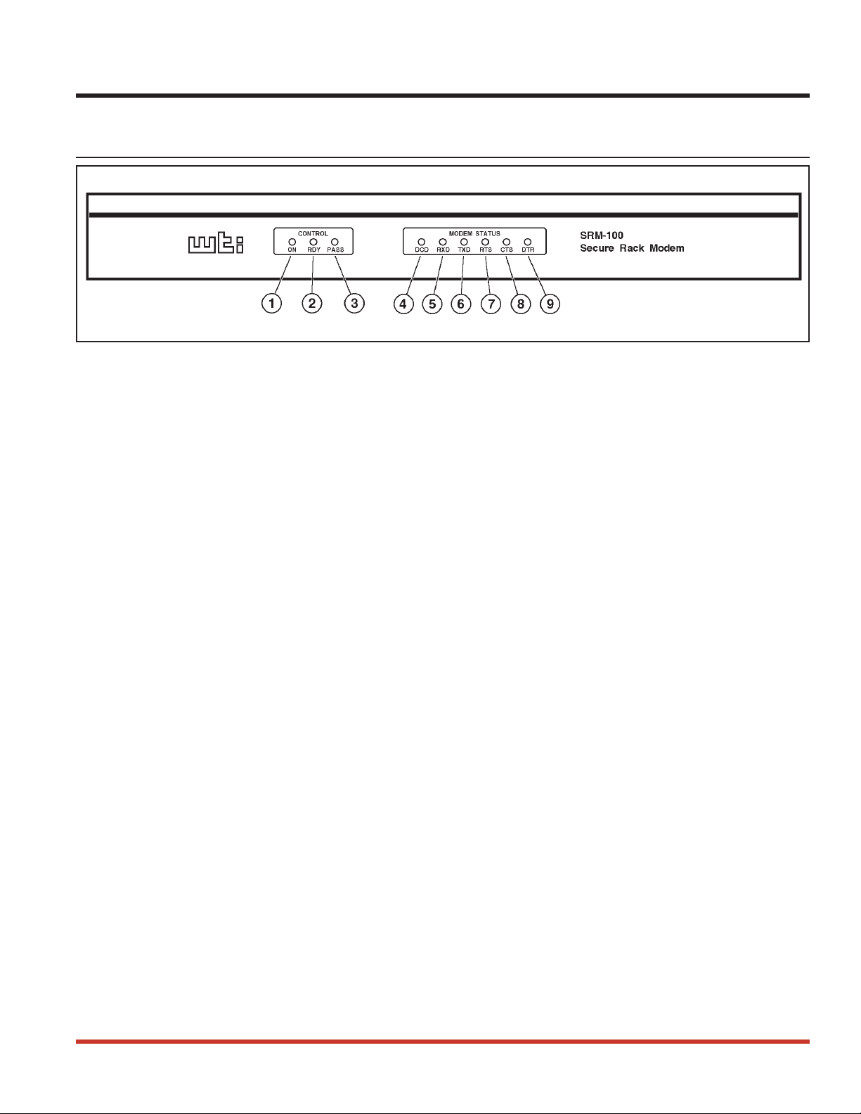
Figure 2.1: Front Panel (Not to Scale)
ON Indicator: Lights when power is applied to the unit.
À
RDY: Flashes to indicate that the unit is ready to receive calls or enter the Command
Á
Mode.
PASS: Lights when a caller has entered a valid password and has been allowed to access
Â
the connected device.
DCD: (Data Carrier Detect) Lights when the DCD signal is high.
Ã
RXD: (Receive Data) Lights when the RXD signal is high.
Ä
TXD: (Transmit Data) Lights when the TXD signal is high.
Å
RTS: (Request to Send) Lights when the RTS signal is high.
Æ
CTS: (Clear to Send) Lights when the CTS signal is high.
Ç
DTR: (Data Terminal Ready) Lights when the DTR signal is high. Note that the DTR
È
signal must be high in order for the modem to communicate. If the DTR signal is low,
the SRM-100 will prompt callers to enter a password, but will disconnect when a valid
password is entered.
2-1
Page 8
SRM-100 - Secure Rack Modem, User's Guide Unit Description
2.2. Back Panel
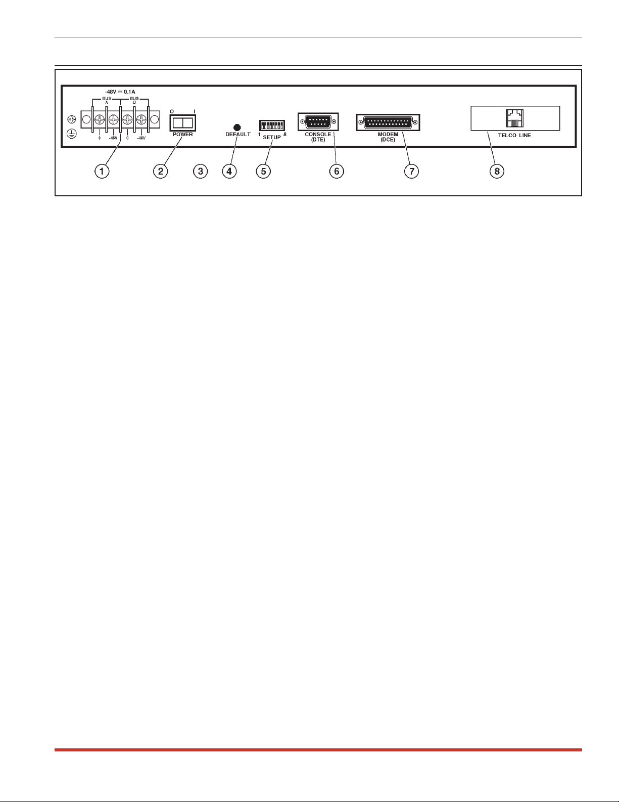
Figure 2.2: Back Panel (DC Version Shown)
Power Input: (DC Unit Shown) The DC version includes a dual-bus terminal block for
À
-48 VDC operation and a ground screw. The AC version includes an IEC-32 inlet for
connection to a three wire (grounded) power cord (supplied with unit).
Power Switch
Á
Voltage Selector Switch: (AC Units Only) For selecting 115 VAC or 230 VAC
Â
operation .
Default Button: Resets unit to default parameters and erases the Password Directory. To
Ã
reset to defaults, power off the unit, then press and hold the Default Button while
pressing the Power Switch to ON. Wait several seconds, then release Default.
Note: The default procedure will clear all menu-selected parameters, and erase the
Password Directory.
SetUp Switches: Eight DIP switches, which select the default Modem Baud Rate,
Ä
Flow Control, Parity, Rings to Answer, Compression, Speaker (On/Off) and Security
Mode. For more information on the SetUp Switches, refer to Section 4.2.
Console Port: For connection to your PC, terminal, or other device. Allows access to
Å
Command Mode. DB9, RS232, DTE configuration. Note that the command mode can
also be accessed via modem as explained in Section 5.1.2. Appendix A.1 describes the
Console Port interface.
Modem Port: For connection to the secure device. The SRM-100 will protect dial-up
Æ
access to this device by requiring a password and/or calling the user back at a predefined
number. Appendix A.2 describes the Modem Port interface.
Telco Line: An RJ-11 Jack, for connection to your telecommunications (telephone) line.
Ç
2-2
Page 9

3. Getting Started
This section provides a brief introduction to the procedures that are used to communicate with
the SRM unit and access the configuration menus. For more detailed instructions regarding
installation and configuration, please refer to Sections 4 through 6.
3.1. Applying Power to the Unit
Connect an appropriate power source to the SRM unit. Note that the SRM is available in both
AC and DC powered versions.
AC Units: Set the Voltage Selector Switch (located on the SRM back panel) to the
·
appropriate voltage. Connect the supplied power cable to the receptacle on the SRM back
panel, then connect the plug to a suitable AC outlet.
DC Units: Remove the protective plastic cover from the DC terminal block, switch off the
·
DC power source, then attach the wires from the -48 VDC power source to the screw
terminals. Connect your ground line to the grounding screw, then replace the protective
cover and switch the DC power source back on.
CAUTION: This device should only be operated with the type of power source
indicated on the instrument nameplate. If you are not sure of the type of power
service available, please contact your local power company.
After connecting the unit to the power source, press the Power Switch to the On position. The
ON indicator should light, and after a brief pause, the RDY indicator should begin to flash.
3.2. Connecting a PC to the Console Port
For this overview, a PC will be connected to the SRM Console Port. This will allow you to
access the Command Mode and display the menus which are used to select configuration
parameters, check connection activity, and define and display user passwords.
Note: Although this overview demonstrates the procedure for communicating with
the unit via the Console Port, the Command Mode can also be accessed via modem
as described in Section 5.1.2.
To connect your PC to the SRM Console Port, proceed as follows:
1. Attach a standard null modem cable to a COM Port on your PC. Make certain to connect
to the COM port that is used by your communications program (e.g. ProComm).
2. Connect the other end of the cable to the Console Port, located on the SRM back panel.
For a description of the Console Port interface, please refer to Appendix A.
3-1
Page 10

SRM-100 - Secure Rack Modem, User's Guide Getting Started
Secure Rack Modem Version: 1.11 Site: (undefined)
COMMANDS
/H Display Help Screen /C View Audit Log
/G View/Set General Parameters /U Utilities
/M View/Set Modem Parameters /X Exit/Disconnect
/E Edit Password Directory
/D View Password Directory
Modem Type: V2.200-V34_AGF_DP1
Reset String: ATZ
Init String: AT&C1&D2E0Q1V1M1S0=1&Q%C3
Hang-Up String: (undefined)
MODEM PORT SETTINGS
Baud Rate: 9600 Result Codes: Verbose
Flow Control: RTS/CTS Speaker: On
Local Echo: Off Error Control: On
Rings to Answer: 1 Compression: On
Quiet Mode: On
Figure 3.1: The SRM-100 Help Screen
3.3. Communicating with the SRM-100
In order to communicate with the SRM unit for the first time, you must set your
communications program (e.g. ProComm) to match the default Console Port parameters. Note
that after you have accessed command mode, you can then use the General Parameters Menu to
select other Console Port parameters as described in Section 5, and then reset your
communications program accordingly.
Start your communications program (e.g. ProComm), and set it to match the following default
Console Port parameters:
·
9600 bps
·
8 Data Bits, 1 Stop Bit
·
No Parity
After setting the communications program to match the default Console Port parameters, press
[Enter] to activate the SRM Command Mode. After a brief pause, the unit should display the
Help Screen shown in Figure 3.1, followed by the "SRM>" command prompt. Note that when
the unit is accessed via the Console Port, a password prompt will not be displayed.
If the Command Prompt and Help Screen are not displayed, check to make certain that the
correct communications parameters have been selected, cable connectors are firmly seated, and
that the cable has been connected to the COM Port that is used by your communications
program.
3-2
Page 11

SRM-100 - Secure Rack Modem, User's Guide Getting Started
When the "SRM>" command prompt is displayed, you can invoke the commands listed in the
Help Menu to display the various configuration menus and status screens. For the purpose of
this overview, it is only recommended to review the information on each menu in order to
familiarize yourself with the unit; it is not necessary to actually enter parameters at the
configuration menus at this time.
1. View/Set General Parameters: From the command prompt, type /G and press [Enter].
The General Parameters Menu will be displayed. This menu is used to set Console Port
communication parameters, define the System Password, and select other general
parameters as described in Section 5.2. Press [Esc] to return to the Main Menu.
2. View/Set Modem Parameters: Type /M and press [Enter] to display the Modem
Parameters menu. This menu is used to select communication parameters for the SRM's
internal modem as described in Section 5.3. Press [Esc] to return to the Main Menu.
3. Utilities Menu: Type /U and press [Enter] to display the Utilities Menu. This menu is
used to access SRM-100 command features, such as the Pass-Through Mode, the
Download Parameters Function, and others. Press [Esc] to return to the Main Menu.
4. Other Menus: At this point, commands such as "View Password Directory" and "View
Audit Log" will not display much information. This is due to the fact that the Password
Directory has not been defined yet, and the Audit Log has not had the opportunity to
record connection activity. If you wish to display these menus, key in the appropriate
command and then press [Enter]. To exit a menu, press [Esc] to return to the
Main Menu.
5. Exit/Disconnect: When you have finished exploring the various SRM command menus,
return to the "SRM>" Command Prompt, and then type /X and press [Enter] to exit from
command mode.
This completes introductory overview of the SRM-100. In order to demonstrate the SRM's
security functions, you must completely install the unit, and define the Password Directory as
explained later in this User's Guide. Please proceed to Sections 4 through 6 for complete
installation and configuration instructions.
3-3
Page 12
4. Hardware Installation
4.1. Connecting Power to the SRM-100
The SRM-100 is available in both AC and DC powered versions. When connecting power to
the SRM, proceed as follows:
CAUTION: This device should only be operated with the type of power source
indicated on the instrument nameplate. If you are not sure of the type of power
service available, please contact your local power company.
4.1.1. AC Powered Units
Set the Voltage Selector Switch (located on the SRM back panel) to the appropriate voltage.
Plug the supplied power cable into the receptacle on the SRM-100 back panel, and then connect
the power cable to a grounded (earthed), 115 VAC outlet.
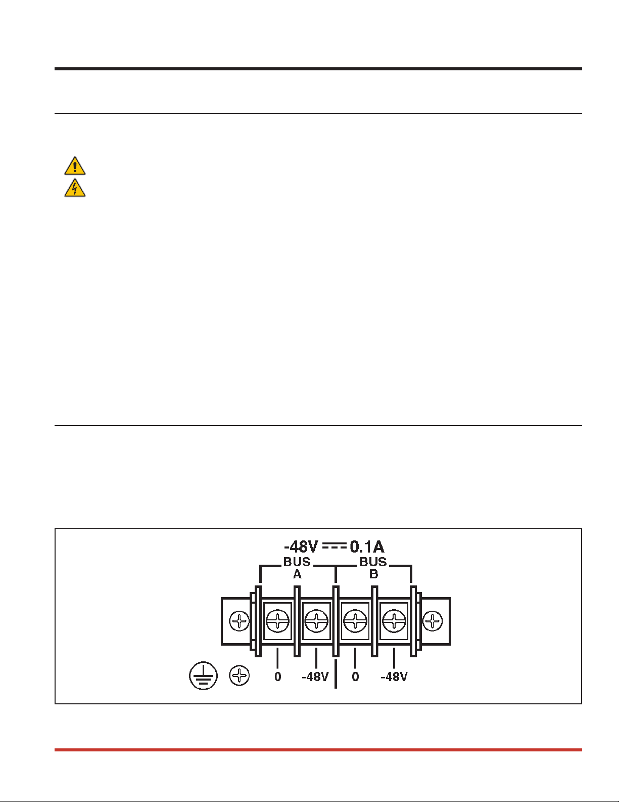
4.1.2. DC Powered Units
When connecting the SRM to your DC power source, first remove the protective plastic cover
from the DC terminal block. Switch off your DC power source, and then attach the wires from
the 48V DC power source to the screw terminals, and connect your ground line to the labeled
ground screw. Then replace the protective cover, and switch the DC power source back on.
Note that the DC terminal block features a dual bus configuration to allow connection to a
back-up power supply.
4.2. SetUp Switches
The SetUp Switches, located on the back panel, select the default settings for Modem Port baud
rate, flow control, parity, rings to answer, and enable/disable ARQ/Compression, the modem
speaker, and the SRM-100 Security Mode.
Note: Operating values for all of these parameters can also be selected via the
SRM’s configuration menus. However, if the unit is reset to default parameters,
these settings will return to the default values selected by the SetUp switches.
Figure 4.1: Terminal Block Assembly and Grounding Screw (DC Units Only)
4-1
Page 13
SRM-100 - Secure Rack Modem, User's Guide Hardware Installation
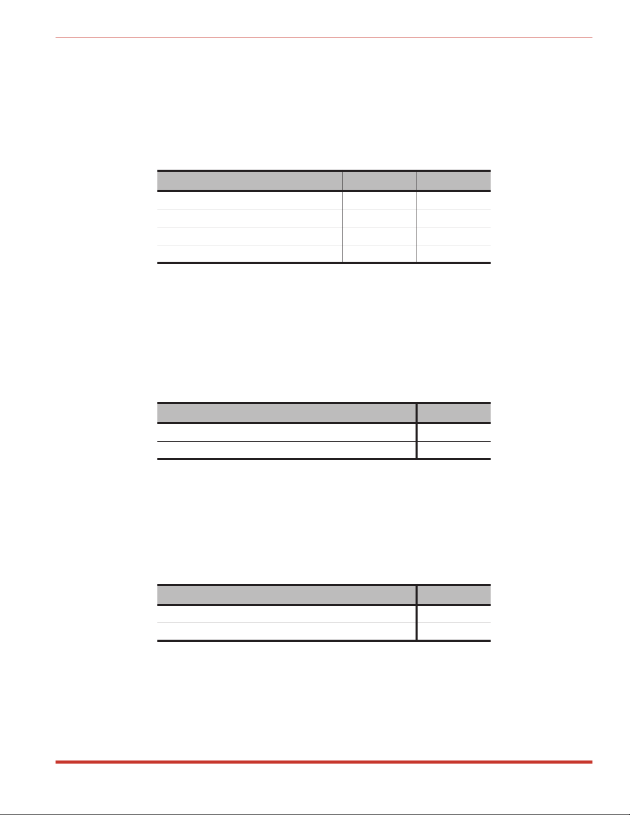
4.2.1. Default Modem Baud Rate (Sw1, Sw2)
SetUp Switches one and two select the default baud rate for the SRM’s internal modem and the
serial Modem Port. The Modem Baud Rate can also be selected via the Modem Parameters
Menu (/M). Note that if the unit is reset to default parameters, the Modem Baud Rate will
return to the default setting selected by SetUp Switches one and two.
Note: Automatic baud rate sensing is disabled. This allows the SRM to function
with devices that do not send an AT command string.
Default Modem Baud Rate Sw1 Sw2
9600 bps * Down Down
38.4K bps Down Up
19.2K bps Up Down
2400 bps Up Up
* = Factory Setting
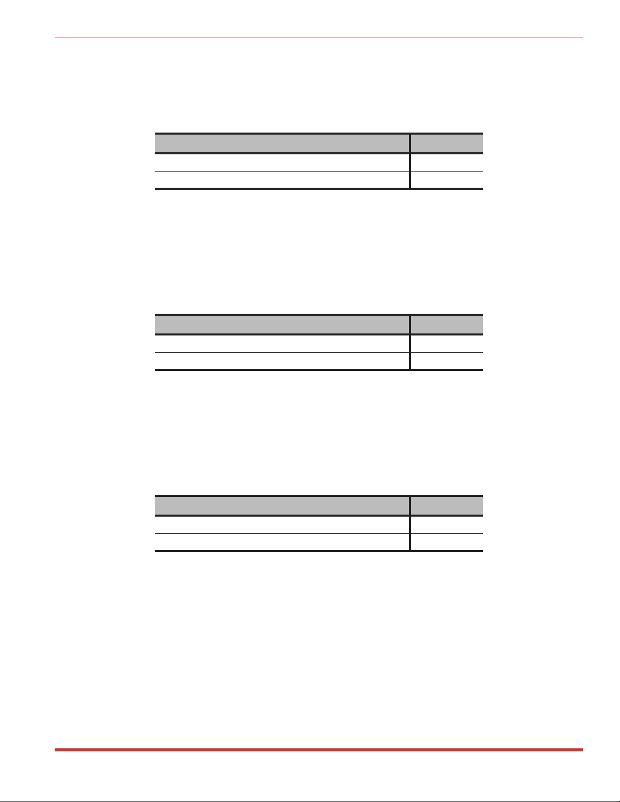
4.2.2. Default Flow Control Format (Sw3)
SetUp Switch three selects the default flow control (handshaking) format for the serial Modem
Port. The flow control format for the serial Modem Port can also be selected via the Modem
Parameters Menu. The flow control format for the internal modem itself is set using AT
commands as described in Section 9. Note that if the unit is reset to default parameters, the
flow control format will return to the default setting selected by SetUp Switch three.
Default Flow Control Format Sw3
RTS/CTS (Hardware) * Down
XON/XOFF (Software) Up
* = Factory Setting
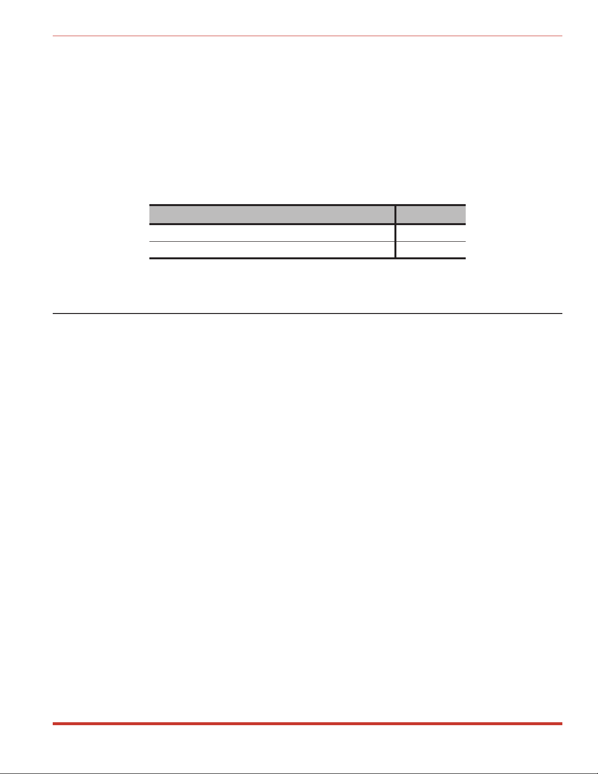
4.2.3. Default Bits and Parity (Sw4)
SetUp Switch four selects the default bits and parity setting for both the internal modem and
the serial Modem Port. The bits and parity can also be selected via the Modem Parameters
Menu (/M). Note that if the unit is reset to default parameters, bits and parity will return to the
default setting selected by SetUp Switch four.
Default Bits and Parity Sw4
8 Bits, No Parity, 1 Stop Bit * Down
7 Bits, Even Parity, 1 Stop Bit Up
* = Factory Setting
4-2
Page 14
SRM-100 - Secure Rack Modem, User's Guide Hardware Installation
4.2.4. Default Rings to Answer (Sw5)
SetUp Switch five selects the default “Rings to Answer” setting. The Rings to Answer setting
can also be defined via the Modem Parameters menu (/M). If the SRM-100 is reset to default
parameters, the Rings to Answer feature will return to the default setting selected by SetUp
Switch five.
Default Rings to Answer Sw5
One * Down
Eight Up
* = Factory Setting
4.2.5. Default ARQ/Compression Status (Sw6)
SetUp Switch six selects the default enabled/disabled status for the ARQ/Compression feature.
The ARQ mode and compression feature can also be enabled or disabled via the Modem
Parameters menu (/M). Note that if the SRM-100 is reset to default parameters, these features
will return to the default settings selected by SetUp Switch six.
Default ARQ / Compression Status Sw6
Enable * Down
Disable Up
* = Factory Setting
4.2.6. Default Modem Speaker Status (Sw7)
SetUp Switch seven selects the default enabled/disabled status for the modem speaker. The
Modem Parameters menu (/M) can also be used to enable/disable the speaker. Note that if the
SRM is reset to default parameters, this feature will return to the setting selected by SetUp
Switch seven.
Default Modem Speaker Status Sw7
On * Down
Off Up
* = Factory Setting
4-3
Page 15
SRM-100 - Secure Rack Modem, User's Guide Hardware Installation
4.2.7. Default Security Mode Status (Sw8)
SetUp Switch eight selects the default enabled/disabled status for the Security Mode. The
Security Mode can also be disabled via the General Parameters Menu (/G). Note that if the
unit is reset to default parameters, the Security Mode feature will return to the default status
selected by SetUp Switch eight.
Note: If the Modem Security mode is disabled (off), all password and security
features will be suppressed, and you will not be able to access the SRM command
mode via modem (although Console Port access to command mode is still allowed).
When the Security Mode is disabled, the SRM will function like a normal nonsecure, modem
Security Mode Sw8
On * Down
Off Up
* = Factory Setting
4.3. Initialize Unit to Default Settings
If SetUp Switch settings are changed, new parameters will not take effect until the SRM-100 is
initialized.
CAUTION: After initialization, menu selected parameters will return to the
settings specified by the SetUp Switches and the Password Directory will also
be erased.
Note: To reset the SRM to default parameters without clearing the Password
Directory, use the "Default Parameters" option in the Utilities menu as described in
Section 7.5.4.
1. Set the SRM-100 Power Switch to the OFF position.
2. Press and hold the Default Button (located on the back panel). Place the SRM-100 Power
Switch in the ON position.
3. Wait for one second (or until the front panel LEDs flash), and then release the Default
Button.
4-4
Page 16

SRM-100 - Secure Rack Modem, User's Guide Hardware Installation
4.4. Cable Connection
Connect cables and telco line as described in the sections that follow. Please refer to
Appendix A for a description of Port interfaces.
4.4.1. Modem Port
The serial Modem Port is used for connection to your secure device. Use a straight wired
modem cable to connect the secure device to the SRM-100 serial Modem Port. For a
description of the Modem Port interface, please refer to Appendix A.
4.4.2. Console Port
The SRM Command Mode allows the system administrator to define passwords, select
configuration parameters, and review the connection activity log. There are two different ways
to access the Command Mode: via modem or via a local PC connected to the SRM
Console Port.
If your SRM will be controlled and configured via the Console Port, use an appropriate cable
to connect the Console Port to the COM port on your PC or terminal. Appendix A describes
the Console Port interface. Note that if your installation will be controlled and configured via
modem, it is not necessary to connect a PC to the Console Port.
4.4.3. Telco Line
Use a standard RJ11 phone cable to connect your phone line outlet to the Telco Line port on the
SRM back panel. If the SRM's Telco Line port includes two RJ11 connectors, connect your
phone line to the connector labeled "Wall" or "Line".
4-5
Page 17

5. Set-Up and Configuration
This section describes the procedures for selecting SRM configuration parameters. The default
SRM parameters are intended to fit the requirements of most applications. Please review the
default settings to determine if any parameters must be changed. In many cases, the factory
defaults will work just fine.
5.1. Command Mode Access
The Command Mode allows the user to select parameters, define passwords, and review the
connection activity log. There are two ways to access the Command Mode; via the Console
Port and via Modem.
Note: While the Command Mode is active, inbound callers will receive a busy
signal.
5.1.1. Access Via the Console Port
When a Local PC or terminal is connected to the SRM Console Port, system administrators can
access the Command Mode as follows:
Note: When the SRM is accessed via the Console Port, the password prompt is not
displayed. The password prompt is always displayed when the unit is accessed via
Modem.
·
PC: Start your communications program (e.g. ProComm) and then press [Enter]. The
SRM Help Screen (see Figure 5.1) will
be displayed.
·
Terminal: Press [Enter]. The Help Screen will be displayed.
If the SRM-100 does not respond, check the following:
·
Console Port Communication Parameters: The SRM Console Port and your
communications program or terminal must be set to use the same communication
parameters. The default Console Port parameters are 9600 bps, No Parity, 8 Data Bits,
One Stop Bit.
·
Correct Port: Make certain that your communications program or terminal is set to use
the Com port that is connected to the SRM Console Port.
5-1
Page 18

SRM-100 - Secure Rack Modem, User's Guide Set-Up and Configuration
Secure Rack Modem Version: 1.11 Site: (undefined)
COMMANDS
/H Display Help Screen /C View Audit Log
/G View/Set General Parameters /U Utilities
/M View/Set Modem Parameters /X Exit/Disconnect
/E Edit Password Directory
/D View Password Directory
Modem Type: V2.200-V34_AGF_DP1
Reset String: ATZ
Init String: AT&C1&D2E0Q1V1M1S0=1&Q%C3
Hang-Up String: (undefined)
MODEM PORT SETTINGS
Baud Rate: 9600 Result Codes: Verbose
Flow Control: RTS/CTS Speaker: On
Local Echo: Off Error Control: On
Rings to Answer: 1 Compression: On
Quiet Mode: On
Figure 5.1: The SRM-100 Help Screen
5.1.2. Access via Modem
To access the SRM Command Mode via modem, dial the number for the phone line connected
to the SRM unit. When the Password Prompt is displayed, key in your System Password
(Default = SUPER) and press [Enter]. The SRM will display the Help Screen as shown in
Figure 5.1. Note that the password is case sensitive.
If the System Dial Back number has been defined (see Sections 5.2 and 7.2.3), the SRM will
dial the defined number before allowing access to the Command Mode. In this case, when the
valid System Password is entered, the SRM will disconnect, and call the System Dial Back
number before allowing access to Command Mode.
If the “Password on Dial Back” feature (see Sections 5.2 and 7.2.4) is enabled, the SRM will
redisplay the password prompt to the answering party. If the System Password is entered by
the answering party, the SRM will allow access the Command Mode.
If the SRM does not respond, check the following:
·
Modem Communication Parameters: The SRM's internal modem and your remote
communications program must be set to use the same communication parameters. Default
modem communication parameters are selected using SetUp Switches one through eight
(Factory Setting = 9600 bps, No Parity, 8 Data Bits, One Stop Bit).
5-2
Page 19

SRM-100 - Secure Rack Modem, User's Guide Set-Up and Configuration
GENERAL PARAMETERS
1. System Password: SUPER
2. System Dial Back #: (undefined)
3. Site ID: (undefined)
4. Real Time Clock: Tue 06/13/2000 11:25:26
5. Console Port Communication: 9600, N, 8, 1
6. Command Echo: On
7. No Activity Timeout 5 Min
8. Password Attempts: 3
9. Password on Dial Back: Off
10. Security Mode: On
11. Audit Log Options: All
12. Dial Back Attempts: 1
13. Dial Back Delay: 30 Sec
Enter Selection,
Press <Esc> to Abort ...
Figure 5.2: The General Parameters Menu
5.2. The General Parameters Menu
The menu shown in Figure 5.2 is used to set the Real Time Clock, and select the System
Password, Site ID, and other general parameters. To access the General Parameters Menu,
activate the SRM command mode as described in Section 5.1, then type /G and press [Enter].
To change the setting for any item in this menu, key in the number for the desired item, press
[Enter], then follow the instructions in the submenu. The General Parameters Menu includes
the following items:
1. System Password: This password protects modem access to the Command Mode. When
a caller connects to the SRM-100, a password prompt is sent. If the System Password is
entered, the caller will then be granted access to the SRM Command Mode. Note that the
System Password is case sensitive. (Up to 16 characters, Default = SUPER).
2. System Dial Back #: When defined, the SRM will dial this number before allowing
modem access to the Command Mode. When a caller contacts the SRM, a password
prompt is sent. If the caller enters the valid System Password, the SRM will disconnect
and then call the System Dial Back number. When the System Dial Back number
answers, the SRM Command Mode will start. (Up to 32 characters, Default = undefined).
Note: While a Dial Back operation is in progress, the SRM is not able to accept
incoming calls, and will not recognize commands entered via the Console Port.
3. Site ID: Defines a text string which can be used to identify the location where the SRM100 is installed. The Site ID message will be displayed at the top of the SRM Help
Screen. (Up to 32 characters, Default = undefined).
4. Real Time Clock: Sets the SRM's internal real time clock and calendar. The SRM uses
the Real Time Clock to record times and dates when logging connection activity. Enter
the correct time using 24 hour (military) format.
5-3
Page 20

SRM-100 - Secure Rack Modem, User's Guide Set-Up and Configuration
5. Console Port Communication: Defines the Baud Rate, Parity Bits, Data Bits, and Stop
Bits for the Console Port. (Default = 9600 bps, No Parity, 8 Data Bits, 1 Stop Bit).
Note: If Console Port parameters are changed, new settings will take effect
immediately, and may effect your ability to communicate with the SRM unit. Make
certain to note newly selected parameters, and set your communications program to
match.
6. Command Echo: Enables/disables the command echo. When enabled, characters sent to
the SRM will be echoed back and shown on the display monitor. (Default = On).
7. No Activity Timeout: Selects the timeout value for both the Console Port and the
internal modem. If no data or command activity is detected during this period, the SRM
will disconnect or exit from command mode. (Default = 5 Min.).
8. Password Attempts: The number of password attempts that will be accepted when a
user attempts to access the SRM via modem. If this number is exceeded, the SRM will
disconnect and terminate the modem connection. (Default = 3).
Note: If the number of password attempts is set to zero, the User Password
requirement is disabled. In this case, if the unit is contacted via modem, the
password prompt will still be displayed, but callers will be allowed to access the
secure device by pressing [Enter] in response to the prompt. Note however, that
the SRM will continue to log access attempts, and the System Password will
continue to protect access to the Command Mode.
9. Password on Dial Back: This item adds an additional layer of security to the Dial Back
feature; when a Dial Back is performed, the SRM will prompt the answering party to
enter a password before allowing access. When this feature is enabled, it will be applied
to both User Password Dial Backs and System Password Dial Backs. Note that the
answering party must enter the same password that was entered to initiate the Dial Back.
(Default = Off).
10. Security Mode: This item can be used to disable the SRM-100’s security features.
When the Security Mode is Off, the SRM will function like a normal, unprotected
modem. Callers will be granted access to the secure device without entering a password.
(Default Determined by SetUp Switch 8, Factory Setting = On).
Notes:
•
When the Security Mode is disabled, the SRM will not prompt callers to enter a
Password before allowing access to the secure device.
•
If the Security Mode is disabled (off), you will not be able to access the SRM
command mode unless SetUp Switch 8 is placed in the Down position, and the
unit is then reinitialized as described in Section 4.3.
5-4
Page 21

SRM-100 - Secure Rack Modem, User's Guide Set-Up and Configuration
11. Audit Log Options: This item determines which type of calls will be recorded in the
SRM’s Audit Log. The SRM can log all connection attempts, only successful attempts, or
only unsuccessful attempts. This log will list the user name, password entered, duration
of the call, and exit status. Section 7.4 describes the Audit Log screen.
(Default = All).
12. Dial Back Attempts: This item determines how many times the SRM will attempt to
contact the Dial Back Number if the initial call is not successful. (Default = 1).
13. Dial Back Delay: Determines how much time will elapse between each Dial Back
Attempt. (Default = 30 Seconds).
When you have finished selecting parameters from the General Parameters menu, press [Esc] to
return to the main Help Screen. Menu selected parameters will be stored in the SRM’s nonvolatile memory.
5-5
Page 22

SRM-100 - Secure Rack Modem, User's Guide Set-Up and Configuration
MODEM PARAMETERS
1. Baud Rate: 9600
2. Bits/Parity: 8-None
3. Stop Bits: 1
4. Flow Control: RTS/CTS
5. Local Echo: Off
6. Rings to Answer: 1
7. Quiet Mode: On
8. Result Codes: Verbose
9. Speaker: On
10. Error Control: On
11. Compression: On
12. Reset String: ATZ
13. Custom Init String: (undefined)
14. Hang-Up String: (undefined)
Enter Selection,
Press <Esc> to abort ...
Figure 5.3: The Modem Parameters Menu
5.3. The Modem Parameters Menu
The Modem Parameters Menu is used to select communication parameters for both the SRM’s
internal modem and the serial Modem Port. To display the Modem Parameters Menu, access
the Command Mode as described in Section 5.1, then type /M and press [Enter].
To change the setting for any item in this menu, key in the number for the desired item, press
[Enter] and then follow the instructions in the submenu. The Modem Parameters Menu
includes the following items:
1. Baud Rate: The operating baud rate for the SRM's modem and serial Modem Port. If
the unit is reinitialized, the baud rate will return to the default value selected by SetUp
Switches One and Two. (Default is Selected by SetUp Switches1&2,
Factory Setting = 9600).
Note: Automatic baud rate sensing is disabled. This allows the SRM to function
with devices that do not send an AT command string.
2. Bits / Parity: The operating Data Bits and Parity Bits for the SRM's internal modem and
serial Modem Port. If the unit is initialized to default settings, the Bits and Parity will
return to the default setting currently selected by SetUp Switch 4. (Default is Determined
by SetUp Switch 4, Factory Setting = 8-None).
3. Stop Bits: The setting for the internal modem. (Default = 1).
4. Flow Control: This item selects the operating flow control format for the SRM’s internal
modem. To set the flow control format for the serial Modem Port, invoke the appropriate
AT command as described in Section 9, or modify the Modem Initialization String as
described under item 13. Note that if the SRM is initialized to defaults, the modem will
return to the default flow control format selected by SetUp Switch 3. (Default
Determined by SetUp Switch 3, Factory Setting = RTS/CTS).
5-6
Page 23

SRM-100 - Secure Rack Modem, User's Guide Set-Up and Configuration
5. Local Echo: Enables / disables the local echo for the SRM’s internal modem.
(Default = Off).
6. Rings to Answer: Determines how many rings will elapse before the SRM’s internal
modem answers an incoming call. Note that if the SRM is reinitialized, the modem will
return to the setting selected by SetUp Switch 5. (Default Determined by SetUp Switch
5, Factory Setting = 1).
7. Quiet Mode: Enables / Disables the Quiet Mode. When enabled, the SRM’s internal
modem will not send confirmation messages in response to AT commands.
(Default = On).
8. Result Codes: Determines whether the SRM will respond to AT commands with Terse
(numeric / abbreviated) or Verbose (English text) messages. For a listing of possible AT
result codes, please refer to Section 11. Note that if the Quiet Mode (see item 7) is
enabled, the SRM will not send responses to AT commands, regardless of which Result
Code setting is selected. (Default = Verbose).
9. Speaker: Enables/disables the modem speaker. (Default = On).
10. Error Control: Enables / Disables the error control function. (Default = On).
11. Compression: Enables / Disables the data compression function. (Default = On).
12. Reset String: If necessary, this item can be used to redefine the Modem Reset String.
(Up to 16 characters, Default = ATZ).
13. Custom Initialization String: This item is used to “customize” the SRM’s modem
initialization string. During configuration, the unit will build an initialization string
based on items selected from the Modem Parameters Menu. This string will consist of
three components; (1) The default string header (AT&C1&D2), (2) the responses to items
1 through 11 in the Modem Parameters Menu, and (3) any special AT commands entered
via item 13. For a listing of available AT commands, please refer to Section 9.
(Up to 16 characters, Default = undefined).
14. Hang-Up String: This item is used to define tasks that are performed after the SRM
hangs up at the end of a communication session. Typically, the Hang-Up string would be
used to clear memory, or reset the modem to a set of user-defined parameters. To define
the Hang-Up String, simply key in the appropriate AT commands for the desired
operation(s). For a listing of available AT commands, please refer to Section 9.
(Up to 16 characters, Default = undefined).
When you have finished selecting modem configuration parameters, press [Esc] to return to the
main Help Screen. User-selected parameters will be saved in the SRM’s non-volatile memory.
5.4. Save Parameters
After the unit has been completely configured, it is recommended to save configuration
parameters to an ASCII file as described in Section 8. This allows quick recovery in the event
that the unit is reset to default parameters, or configuration is accidentally deleted or altered.
5-7
Page 24

6. The Password Directory
When the SRM-100 is properly configured, each inbound caller will be prompted to enter a
password before being allowed to access the secure device. The Password Directory is
basically a listing of all valid user passwords, user names, and their associated Dial Back
numbers.
The SRM-100 will accept up to 100 User Passwords and one System Password. User
passwords allow access to the secure device connected to the SRM-100 serial Modem Port, and
the System Password allows access to the Command Mode. As discussed in Section 5.2, the
System Password is defined via the General Parameters Menu. The procedure for defining
User Passwords is described in this chapter.
To add passwords to the directory or edit existing User Passwords, make certain the command
mode is active, then type /E and press [Enter]. The SRM-100 will display the Edit Password
Directory Menu shown in Figure 6.1. This menu offers three options; Add Name/Password,
Edit/Delete from List, and Edit/Delete from Search.
After defining the Password Directory, you may wish to review its contents. Section 6.4
describes the procedure for displaying the Password Directory and explains the directory
screen.
• User Passwords do not allow access to the SRM Command Mode.
• In order for the SRM to protect access to the secure device, the Security Mode
must be enabled (see Section 5.2) and at least one User Password must be defined.
EDIT PASSWORD DIRECTORY
1. Add Name/Password
2. Edit/Delete from List
3. Edit/Delete from Search
Enter Selection,
Press <Esc> to abort ...
Figure 6.1: The Edit Password Directory Menu
Notes:
6-1
Page 25

SRM-100 - Secure Rack Modem, User's Guide The Password Directory
6.1. Add Name / Password
To add new User Passwords and Names to the Password Directory, go to the Edit Password
Directory Menu (/E), type 1 (Add Name / Password) and press [Enter]. The SRM will display
a submenu that contains the following items:
1. Name: This item assigns a Name to each User Password. Note that the SRM will not
prompt callers to enter the User Name in order to log in. This name is used only for
internal accounting purposes; and to associate each password with a specific client or
employee. (Up to 16 characters).
Note: The SRM will not accept duplicate user names or passwords. The unit will
display an error message if you attempt to define a name or password that is already
in use.
2. Password: This item assigns a Password for each user. When a caller attempts to log on
to the SRM, a valid User Password must be entered in order to access the secure device.
(Case sensitive, Up to 16 characters).
3. Dial Back Number: This item can assign a Dial Back Number to each User Password.
If the Dial Back Number is not defined, a caller who accesses the SRM with this User
Password will be granted immediate access to the secure device. If the Dial Back
Number is defined, when a caller enters this User Password, the SRM will disconnect,
call the assigned Dial Back Number, and then allow the answering party to access to the
secure device. (Up to 32 characters)
Notes:
• The SRM can be configured to perform a Dial Back for some User Passwords,
while providing immediate access to other User Passwords.
• While a Dial Back operation is in progress, the SRM is not able to accept
incoming calls, and will not recognize commands entered via the Console Port.
• If the initial call is not successful, the SRM will repeat the Dial Back procedure as
specified by item 12 (Dial Back Attempts) and item 13 (Dial Back Delay) in the
General Parameters Menu (see Section 5.2).
4. Save Entry: This item stores the Password, Name, and Dial Back Number in the
Password Directory. If you are satisfied with the data entered at prompts 1 through 3,
type 4 and press [Enter] to save this information in non-volatile memory.
After each password is saved, the SRM-100 will redisplay the Add Name/Password menu. To
continue to add names and passwords, repeat steps one through four above. If you have
finished adding passwords, press [Esc] to return to the Edit Password Directory Menu.
6-2
Page 26

SRM-100 - Secure Rack Modem, User's Guide The Password Directory
EDIT/DELETE NAME/PASSWORD:
1. Name: A. User
2. Password: secret
3. Dial Back #: 15555551212
4. Save Entry
5. Delete Entry
Type "<" <Enter> previous entry, ">" <Enter> next entry,
<number><Enter> to select item,
<ESC> to abort ...
Figure 6.2: The Edit/Delete Name/Password Menu
6.2. Edit / Delete from List
Options 2 and 3 in the Edit Password Directory Menu are used to edit and/or delete passwords
from the Password Directory. The difference between these two options is the manner in which
the desired password is selected. When Option 2 is used, the desired password is selected from
a list of all passwords. When Option 3 is used, the password is selected by searching for a
specific password or user name.
To use Option 2 to edit or delete User Passwords, proceed as follows:
1. Go to the Edit Password Directory Menu (/E). Type 2 (Edit / Delete from List) and press
[Enter].
2. The SRM will display the first line of the Password Directory.
a) To select a password, press > or < until the desired password appears at the bottom of
the list. The password at the bottom of the list is the currently selected password.
b) To display the next 15 lines of the directory, press [Enter].
3. When the desired password appears at the bottom of the list, press E. The Menu shown in
Figure 6.2 will be displayed. Note that the password that appears at the bottom of the list
is the selected password.
4. Edit Password: To edit the selected password, type the number for the field that you
wish to change and follow the instructions in the submenu.
a) For example, to change the Dial Back Number for the selected password, type 3,
press [Enter], and then key in the new number as described in the submenu.
b) When you have finished editing the password, return to the Edit/Delete
Name/Password Menu; type 4 and press [Enter] to save the edited password to the
Password Directory.
c) To edit another password type > and press [Enter] for the next password, or type <
and press [Enter] for the previous password.
d) To exit from the Edit/Delete Name/Password Menu, press [Esc], the SRM will display
the new listing for the edited password. To return to the main help screen, press
[Esc], or type /H and press [Enter] .
6-3
Page 27

SRM-100 - Secure Rack Modem, User's Guide The Password Directory
5. Delete Password: To delete the selected password, type 5 and press [Enter].
a) The SRM-100 will ask for confirmation, and then delete the selected password from
the directory. Note that passwords cannot be “undeleted”. After you confirm that the
password should be deleted, the SRM will display the next password in the list.
b) To continue to delete or edit passwords, use the > and < keys to scroll through the list
until the desired password is selected (appears at bottom of list). Then press E to edit
or delete the next password.
c) To exit from the Edit / Delete Name / Password Menu, press [Esc], or type /H and
press [Enter] to return to the main Help Screen.
6.3. Edit / Delete from Search
When Option 3 is used to edit or delete passwords, the password is selected by searching for
the specific password or user name. To search for the specific password to be edited or
deleted, proceed as follows:
1. From the Edit Password Directory Menu (/E). Type 3 (Edit / Delete from Search) and
press [Enter].
2. The SRM will display a menu which offers the option to search by name or by password.
a) To search by name, type 1 and press [Enter]. To search by user password, type 2 and
press [Enter].
b) If the desired name or password is found, the SRM-100 will display the Edit/Delete
Name/Password Menu as shown in Figure 6.2.
3. Edit Password: To edit the selected name / password, type the number for the field that
you wish to change and follow the instructions in the submenu.
a) For example, to change the Dial Back Number for the selected password, type 3,
press [Enter], and then key in the new number as described in the submenu.
b) When you have finished editing the password, return to the Edit / Delete Name /
Password Menu; type 4 and press [Enter] to save the edited password.
c) To edit another password type > and press [Enter] for the next password, or type <
and press [Enter] for the previous password.
d) To exit from the Edit / Delete Name / Password Menu, press [Esc], the SRM will
display the listing for the edited password. To return to the main help screen, press
[Esc], or type /H and press [Enter] .
4. Delete Password: To delete the selected password, type 5 and press [Enter].
a) The SRM-100 will ask for confirmation, and then delete the selected password from
the directory. Note that passwords cannot be "undeleted". After you confirm that the
password should be deleted, the SRM will display the next password in the list.
b) To continue to delete or edit passwords, use the > and < keys to scroll through the
list until the desired password is selected (appears at bottom of list). Then press E to
edit or delete the next password.
c) To exit from the Edit / Delete Name / Password Menu, press [Esc], or type /H and
press [Enter] to return to the main Help Screen.
6-4
Page 28

SRM-100 - Secure Rack Modem, User's Guide The Password Directory
Name Password Dial Back # Activity
-----------------------------------------------------------------------------A. Lincoln stovepipehat 19495551234 12
B. Ross flag (undefined) 11
B. Ruth homerun (undefined) 15
C. Coolidge silentcal (undefined) 14
D. Crocket coonskincap 15155551111 0
D. Madison cake (undefined) 5
F. Roosevelt dime 17145554321 9
G. Washington cherrytree (undefined) 31
N. Armstrong moon (undefined) 3
P. Revere horse (undefined) 23
T. Jefferson nickel 12135559876 15
T. Roosevelt roughride 12145553741 8
1234567890123456 1234567890123456 12345678901234567890123456789012 0
Reached End of Directory.
Press <Enter> to continue ...
Figure 6.3: The Password Directory (Sample Data Shown)
6.4. Viewing the Password Directory
After you have added several names and passwords, you may wish to view the Password
Directory in order to verify that data has been correctly entered. To display a screen which
lists all currently defined User Names and User Passwords, type /D and press [Enter]. The
SRM will display the screen shown in Figure 6.3.
Note: This command will not display the System Password. To display the System
Password, you must access the General Parameters menu (/G).
The Password Directory display includes the following items:
1. Name: The user defined name for this password. Note that callers will not be prompted
to enter their User Name; only the password. The "Name" is generally used to identify
the user or client associated with each password.
Note: In the Password Directory, lines are sorted alphabetically by name.
Uppercase letters are listed before lower case letters, and letters are listed before
symbols.
2. Password: The User Password that is currently defined for this name. Note that the
password is case sensitive.
3. Dial Back Number: The Dial Back Number currently defined for this name. Note that if
the Dial Back Number has not been defined, this field will read "undefined".
4. Activity: The number of times that this password has been used since the last time the
activity counter was reset. The procedure for resetting the activity counter is discussed in
Section 6.5.
6-5
Page 29

SRM-100 - Secure Rack Modem, User's Guide The Password Directory
6.5. Zero Activity Counters
In order to track password activity, the Password Directory screen lists the number of access
attempts for each user password/name. From time to time, you may wish to re-zero these
counters to obtain a more accurate picture of password activity. To Zero the Activity Counters,
proceed as follows:
1. Access the SRM-100 Command Mode as described in Section 5.1.
2. When the "SRM>" command prompt appears, type /U and press [Enter]. The Utilities
Menu will appear as shown in Figure 7.2.
3. From the Utilities menu, type 1, then press [Enter] and follow the instructions in the
submenu.
6.6. Save Parameters
After the Password Directory has been defined, it is recommended to save SRM configuration
parameters and the Password Directory to an ASCII file as described in Section 8. This allows
quick recovery in the event that the unit is reset to default parameters, or configuration is
accidentally deleted or altered.
6-6
Page 30

7. Operation
7.1. SRM Operating Modes
The SRM-100 provides three separate operating modes; the User Mode, the Command Mode,
and the Unsecured Mode.
7.1.1. User Mode
The User Mode is activated when a caller enters a User Password at the login prompt. The
User Mode only allows the caller to access the secure device which is connected to the serial
modem port. The User Mode does not allow access to configuration menus or the Password
Directory.
7.1.2. Command Mode
The Command Mode is activated when a caller enters the System Password at the login prompt,
or when a local terminal or PC accesses the SRM via the Console Port. The Command Mode
allows access to all SRM-100 configuration menus, and is used to define passwords and select
operating parameters as described in Sections 5 and 6 of this User's Guide.
7.1.3. Unsecured Mode
When the Unsecured Mode is active, the SRM will function like a normal, unprotected modem.
Callers will be allowed to access the secure device without entering a password. The
Unsecured Mode is activated by placing SetUp Switch 8 in the Up position (see Section 4.2.7),
or by accessing the General Parameters Menu (see Section 5.2) and disabling the Security
Mode. Note that when the Unsecured mode is active, you will not be able to access the
Command Mode. In order to return to password-protected operation, you must enable the
Security Mode by placing SetUp Switch 8 in the Down position, and then reinitialize the SRM
unit as described in Section 4.3.
7.2. Password Functions
The SRM-100 features two different types of passwords; the System Password and the User
Passwords. The System Password allows system administrators to invoke configuration
commands and review connection activity. The User Passwords allow callers to access the
secure device that is connected to the SRM unit.
7.2.1. The System Password
The System Password protects modem access to the SRM-100 Command Mode. The Command
Mode allows system administrators to invoke commands to select configuration parameters,
edit the password directory, and review connection activity.
The SRM-100 allows definition of one System Password, which can be defined via the General
Parameters Menu (/G). The default System Password is "SUPER". Note that the System
Password is case sensitive.
7-1
Page 31

SRM-100 - Secure Rack Modem, User's Guide Operation
The System Password is not required when the Command Mode is accessed via the Console
Port; this password is only used when the SRM-100 is contacted via modem. When the unit
answers an incoming call, the password prompt is displayed. If the System Password is
entered, the caller will be granted access to the Command Mode; if a User Password is entered,
the caller will be allowed to access the secure device.
Notes:
When defining the System Password, it is strongly recommended that you record
•
the password for future reference.
If you forget or lose your System Password, you will not be able to access the
•
SRM-100 Command Mode via modem. In this case, you will need to access the
Command Mode locally, via the Console Port, and then redefine the System
Password. (Default=SUPER).
7.2.2. User Passwords
User Passwords allow callers to access the secure device. User Passwords do not grant access
to the Command Mode. The SRM-100 allows definition of up to one hundred User Passwords,
which are defined via the Edit Password Directory Menu (/E) as described in Section 6. Note
that User Passwords are case sensitive.
7.2.3. Dial Back Numbers
Both the System Password and the User Passwords allow definition of a Dial Back Number.
When a Dial Back Number has been defined for a given password, callers who enter that
password will not be granted immediate access. Instead, when a valid password is entered, the
SRM will disconnect, call the defined Dial Back Number for the password, and then grant
access to the answering party.
When a Dial Back for a System Password is performed, the SRM-100 will allow access to the
Command Mode. When a Dial Back for a User Password is performed, the SRM will allow
access to the secure device. The System Dial Back Number is defined via the General
Parameters Menu (/G), and the User Dial Back Numbers are defined via the Edit Password
Directory Menu (/E).
Note that when User Dial Back Numbers are defined, the SRM can be configured to perform a
Dial Back for some User Passwords, while granting immediate access to other User Passwords.
If the Dial Back Number is not defined for a given password, then a Dial Back will not be
performed when that password is entered at the log in prompt.
Notes:
•
Callers will receive a busy signal while the Dial Back operation is in progress.
•
If the initial call is not successful, the SRM will repeat the Dial Back procedure as
specified by item 12 (Dial Back Attempts) and item 13 (Dial Back Delay) in the
General Parameters Menu (see Section 5.2).
7-2
Page 32

SRM-100 - Secure Rack Modem, User's Guide Operation
7.2.4. Password on Dial Back
The Password on Dial Back option provides an additional level of security when Dial Back
numbers are used; when a Dial Back is performed, the SRM will prompt the answering party to
enter a password before allowing access. When this feature is enabled at the System
Parameters Menu, it will be applied to both System Passwords and User Passwords.
Each time the SRM is accessed via modem, a password prompt is displayed, and the caller will
then key in a User Password or System Password. If the password is recognized as valid, the
SRM will check to see if a Dial Back Number has been assigned to that password.
If a Dial Back Number has been assigned, the SRM will hang-up, and call the Dial Back
Number. If "Password on Dial Back" has been enabled, the answering party will again be
prompted to enter a password. If the System Password is entered, the answering party will be
allowed to access Command Mode. If a User Password is entered, the answering party will be
allowed to access the secure device.
Note that the password entered at the Dial Back prompt must be the same password that was
entered at the dial in prompt.
7.3. Suppressing the Confirmation Prompt
The SRM will display a confirmation prompt before executing commands such as /X
(exit/disconnect), or performing tasks such as clearing the Audit Log. The Confirmation
prompt provides one last chance to terminate a command before it is executed.
In some cases, you may wish to execute a command or perform a task without being prompted
for confirmation. To suppress the confirmation prompt, include the ",Y" argument in the SRM
command line.
Examples:
·
Exit/Disconnect: To exit from Command Mode without displaying the confirmation
prompt, type /X,Y and press [Enter].
·
Delete Audit Log: The Utilities menu includes a function
(item 2) which allows you to clear all logged connection attempts. If you type 2 and press
[Enter], the SRM will display a confirmation prompt before clearing connection attempts.
If you type 2,Y and press [Enter], the SRM will clear the Audit Log without displaying
the confirmation prompt.
7-3
Page 33

SRM-100 - Secure Rack Modem, User's Guide Operation
Date Time Duration Port Name Password Entry Exit Status
-----------------------------------------------------------------------------08/11 09:53 00:00:00 M(out) No Answer
08/11 09:49 00:00:00 M(in) T. Jefferson nickel Dialing Back
08/11 09:42 00:01:05 C Exit Command
08/11 09:39 00:00:41 M(in) G. Washington cherrytree Connection Lost
08/11 09:37 00:01:35 M(out) DTR Drop
08/11 09:37 00:00:00 M(in) A. Lincoln stovepipehat Dialing Back
08/11 09:33 00:02:15 C Exit Command
08/11 09:27 00:03:45 M(in) P. Revere horse No Activity
08/11 09:22 00:00:00 M(in) secret Invalid Password
08/11 09:17 00:03:05 M(in) F. Roosevelt dime DTR Drop
08/11 09:07 00:05:18 M(in) B. Ross flag Connection Lost
08/11 09:05 00:01:30 M(out) Connection Lost
08/11 09:05 00:00:00 M(in) A. Jackson twenty Dialing Back
08/11 08:52 00:03:27 M(in) G. Washington cherrytree No Activity
08/11 08:43 00:05:48 C No Activity
08/11 08:40 00:00:00 M(in) guest Invalid Password
08/11 08:39 00:00:00 M(in) test Invalid Password
08/11 08:36 00:02:31 M(in) C. Coolidge silentcal DTR Drop
Press: <Enter> Next 20 entries, <ESC> to abort ...
Figure 7.1: The Audit Log
7.4. Viewing the Audit Log
The Audit Log provides a means to track password use and access attempts. Item 11 in the
General Parameters menu (/G) determines which type of access attempts will be recorded. The
Audit Log can be configured to record all connection attempts, only successful attempts, or
only unsuccessful attempts.
Note that the Audit Log can only be viewed via the SRM command mode. To display the Audit
Log, access the command mode as described in Section 5.1, then type /C and press [Enter].
Events are listed in reverse chronological order, with the most recent attempts appearing at the
top of the list.
The Audit Log will list only the most recent 100 connection attempts. After 100 events are
recorded, the log will wrap-around; and older events will be deleted as each new event is
added. If you wish to clear the audit log and delete all entries, access Command Mode, then
type /U and press [Enter], the Utilities Menu will appear. From the Utilities Menu, type 2
(Delete Audit Log), press [Enter] and follow the instructions in the submenu. Note that
deleted log entries cannot be recovered.
To view access activity for each individual password, type /D and press [Enter] to display the
Password Directory as described in Section 6.4.
7-4
Page 34

SRM-100 - Secure Rack Modem, User's Guide Operation
As shown in Figure 7.1, the Audit Log screen includes the date, time, call duration, port used,
user name, password entered, and exit status. Note the following:
1. Port Used: Lists the port used for each connection attempt:
M(out): An outbound call placed by the modem. This usually indicates that the SRM
•
has performed a dialback in response to a user password entered at login.
M(in): An inbound call received by the modem.
•
C (Console Port): The Command Mode was accessed via the Console Port.
•
S (Serial Port): The device connected to the serial modem port has accessed the
•
modem using the pass-through function.
2. Name: The User Name for the password entered at login. If an invalid password is
entered, this column will be blank.
3. Password Entry: The last password entered during this connection attempt. Note that
although the SRM will allow 1, 3, 5, 9, or an infinite number of password attempts, the
Audit Log will list the last password entered at the login prompt; earlier password
attempts will not be listed.
4. Exit Status: The reason for disconnection:
• Exit Command: The caller entered the /X command to exit from the SRM Command
Mode.
• Invalid Password: The caller did not enter a valid password within the allowed
number of password attempts.
• Dialing Back: The SRM ended the connection in order to perform a dialback
operation. For more information on the dialback function, please refer to Section 7.2.3.
• No Answer: The SRM has performed a Dial Back operation, and the Dialback Number
did not answer.
•
Connection Lost: The party on the other end of the phone line has either hung-up or
unplugged the phone line.
•
DTR Drop: The connection was terminated because the SRM dropped the DTR signal,
did not receive a DTR signal, or detected a bad line.
•
No Activity: The connection has timed out because of a lack of data activity. For more
information on the timeout feature, please refer to Section 5.2.
7-5
Page 35

SRM-100 - Secure Rack Modem, User's Guide Operation
UTILITIES
1. Zero All Activity Counters
2. Delete Audit Log
3. Delete Entire Password Directory
4. Default Parameters
5. Send Test Message (ESC to Stop)
6. Upload Parameters
7. Download Parameters
8. Pass-Through (Console - Modem)
Enter Selection,
Press <Esc> to Abort ...
Figure 7.2: The Utilities Menu
7.5. The Utilities Menu
The Utilities Menu allows access to a series of command functions that are related to general
operation and maintenance of the SRM unit. To display the Utilities menu, access the SRM
Command Mode as described in Section 5.1, then type /U and press [Enter]. The menu shown
in Figure 7.2 will appear. The various functions of the Utilities menu are discussed in the
sections that follow.
7.5.1. Zero All Activity Counters
This command is used to reset the counters that track connection activity for each password.
To zero all activity counters, access the Utilities Menu, then type 1, press [Enter], and follow
the instructions in the submenu.
To view the password activity counters, access the SRM Command Mode as described in
Section 5.1, type /D and press [Enter] to display the Password Directory. For more
information, please refer to Sections 6.4 and 6.5.
7.5.2. Delete Audit Log
This command is used to clear all records from the Audit Log. To erase all Audit Log entries,
access the Utilities menu, type 2 and then press [Enter].
Note: Once the Audit Log has been cleared, the deleted connection activity records
cannot be recovered.
7.5.3. Delete Entire Password Directory
This function is used to completely clear the entire SRM password. To completely clear all
entries from the SRM Password Directory, first access the Utilities Menu as described above.
When the Utilities Menu appears, type 3, press [Enter], and follow the instructions in the
submenu.
Note: When this function is performed, the entire SRM password directory will be
cleared. The Password Directory cannot be restored unless parameters have been
previously saved to an ASCII file as described in Section 8.
7-6
Page 36

SRM-100 - Secure Rack Modem, User's Guide Operation
7.5.4. Default Parameters
This option allows the system administrator to reset the unit to default parameters without
deleting the Password Directory. To clear all menu selected parameters except the Password
Directory, and return the SRM-100 to its default configuration, first access the Utilities Menu
as described in Section 7.5. When the Utilities menu appears, type 4, press [Enter], and
follow the instructions in the submenu.
Notes:
When the SRM-100 is reset to default parameters, all menu-selected parameters
•
will be cleared. Menu selected parameters cannot be recovered unless they have
been saved to an ASCII text file as described in Section 8.
When the "Default Parameters" function is performed via modem, the SRM will
•
not immediately reset modem parameters. The unit will reset all other parameters,
wait for the caller to disconnect, and then reset modem parameters.
7.5.5. Send Test Message
This option allows the system administrator to send a test message via the Console Port or
telecommunications line. If the SRM Command Mode has been accessed via the Console Port,
the Test Message will be sent out the Console Port; if the Command Mode has been accessed
via modem, the Test Message will be sent via the telecommunications line.
This Test Message is used to test communication with a remote device that has accessed the
SRM Command Mode via modem, or to test communication with the local device connected to
the Console Port. To send the Test Message, proceed as follows:
1. Access the SRM Command Mode as described in Section 5.1.
2. When the "SRM>" command prompt appears, type /U and press [Enter]. The Utilities
Menu will appear as shown in Figure 7.2.
3. From the Utilities Menu, type 5 and press [Enter].
a) If you have accessed the SRM Command Mode via the Console Port, the Test
Message will then be sent out the Console Port.
b) If you have accessed the SRM Command Mode via modem, the Test Message will
then be sent out the telecommunications line.
4. To terminate the Test Message, press the [Esc] key.
7.5.6. Upload Parameters
This function is used to restore SRM parameters that have been saved to an ASCII text file
using the Utilities Menu's "Download Parameters" function. To restore saved SRM parameters,
please refer to the instructions in Section 8.1.
7.5.7. Download Parameters
This function is used to save user-selected SRM parameters to an ASCII text file on your PC or
control device. To save SRM parameters, please refer to the instructions in Section 8.2.
7-7
Page 37

SRM-100 - Secure Rack Modem, User's Guide Operation
7.5.8. Pass-Through Mode (Console-Modem)
The Pass-Through Mode allows communication between the device connected to the Console
Port and the SRM’s internal modem.
When the Pass-Through Mode is active, the Console Port can access the modem in order to
place outbound calls, or invoke any of the AT commands listed in Section 9.
Note that when the Command Mode is accessed via modem, the Pass-Through Mode can also
allow a remote user to access a control device connected to the Console Port.
To activate the Pass-Through Mode, proceed as follows:
1. Access the Command Mode as described in Section 5.1.
2. When the "SRM>" command prompt appears, type /U and press [Enter]. The Utilities
Menu will appear as shown in Figure 7.2.
3. From the Utilities menu, type 8, then press [Enter] and follow the instructions in the
submenu.
4. To exit from Pass-Through Mode and return to the Command Mode, type /X and press
[Enter].
7-8
Page 38

8. Saving and Restoring Parameters and
Password Directory
After the SRM-100 has been properly configured and the Password Directory has been defined,
configuration parameters and the Password Directory can be saved as an ASCII text file. Later,
if the configuration is accidentally altered, the file can be uploaded to automatically
reconfigure the unit without the need to manually assign each parameter and password.
Saved parameters and passwords can also be uploaded to other
SRM-100 units. This allows rapid set-up when several units will be configured with the same
parameters and password directory.
The “Save Parameters” procedure can be performed from any communications program (e.g.
ProComm, Hyperterminal, etc.), that allows downloading of ASCII files.
8.1. Sending Parameters to a File
1. Start your communications program and access the SRM Command Mode as described in
Section 5.1.
2. When the command prompt appears, type /U and press [Enter].
a) The Utilities Menu will appear. From the Utilities Menu, type 7 and press [Enter].
The SRM will prompt you to configure your communications program to receive an
ASCII download.
b) Set your communications program to receive an ASCII format download, and specify
a name for a file that will receive the saved parameters (e.g. SRM.PAR).
c) Make certain to disable your communication program's Line Wrap function. This will
prevent command lines from being broken in two during transmission.
3. When the communications program is ready to receive the file, return to the SRM
Command Mode and press [Enter] to proceed with the download. Menu selected
parameters and the currently defined Password Directory will be saved on your hard drive
in the file specified in Step 2 above.
4. The SRM will send a series of ASCII command lines which specify the currently selected
SRM parameters.
8-1
Page 39

SRM-100 - Secure Rack Modem, User's Guide Saving and Restoring Parameters and Password Directory
8.2. Restoring Saved Parameters
Once menu selected parameters and the Password Directory have been saved, the parameters
file can be uploaded to the SRM to quickly configure the unit without the need to manually
enter each parameter and password. To restore saved parameters, proceed as follows:
Note: When the "Upload Parameters" function is performed via modem, the SRM
will not immediately reset modem parameters. The unit will reset all other
parameters, wait for the caller to disconnect, and then reset modem parameters..
1. Start your communications program and access the SRM Command Mode via the Console
Port, or via modem using the System Password.
2. When the command prompt appears, type /U and press [Enter].
a) The Utilities Menu will appear. From the Utilities Menu, type 6 and press [Enter].
The SRM will display a message which indicates that the unit is ready to receive the
parameters file.
b) Set your communications program to upload an ASCII text file using the file name
specified in Section 8.1. When the communications program is ready, begin the
upload procedure.
3. The saved parameters file will be sent to the SRM-100, and the saved parameters and
Password Directory will be restored. When the upload is complete, make certain to
terminate the communication program’s upload mode.
8-2
Page 40

9. Modem Command Set (AT Commands)
In addition to the SRM's menu driven configuration functions, the internal modem will also
accept standard Rockwell format AT commands. This section describes the AT command set,
and lists the function of each command.
The AT command set is used to select advanced modem configuration parameters, which are
not available via the SRM's menuing system. AT commands can be sent directly to the modem,
or added to the user defined initialization string via item 13 (Custom Init. String) in the SRM's
Modem Parameters menu (see Section 5.3).
9.1. Communicating with the Internal Modem
In order to invoke AT commands, you must communicate directly with the SRM's internal
modem. The Modem Command mode is only available via the Console Port or the serial
modem port; inbound callers cannot communicate directly with the modem. To send AT
commands to the SRM's internal modem proceed as follows:
1. Via Console Port: Access the SRM command Mode as described in Section 5.1.1.
a) When the "SRM>" command prompt appears, type /U and press [Enter] to display
the SRM Utilities Screen.
b) When the Utilities Screen appears, type 8 and press [Enter] to activate the Pass-
Through mode. When the Pass-Through Mode is active, the device connected to the
Console Port can send AT commands directly to the SRM's internal modem.
c) To exit the Pass-Through Mode, type /X and press [Enter], the unit will return to the
"SRM>" command prompt.
2. Via Modem Port: The device connected to the SRM's Modem Port can also issue AT
commands. Go to the secure device and start your communications program (e.g.
ProComm). Make certain that the communications program is configured to use the same
COM port that is connected to the SRM.
9-1
Page 41

SRM-100 - Secure Rack Modem, User's Guide Modem Command Set (AT Commands)
ACTIVE PROFILE
B1 E0 L1 M1 N1 Q1 T V1 W0 X4 Y0 &C1 &D2 &G0 &J0 &K3 &Q5 &R1 &S0 &T5 &X0 &Y0
S00:001 S01:000 S02:043 S03:013 S04:010 S05:008 S06:002 S07:050 S08:002 S09:006
S10:014 S11:095 S12:050 S18:000 S25:005 S26:001 S36:007 S37:000 S38:020 S44:020
S46:138 S48:007 S95:000
STORED PROFILE 0
B1 E1 L1 M1 N1 Q0 T V1 W0 X4 Y0 &C1 &D2 &G0 &J0 &K3 &Q5 &R1 &S0 &T5 &X0
S00:000 S02:043 S06:002 S07:050 S08:002 S09:006 S10:014 S11:095 S12:050 S18:000
S36:007 S37:000 S40:104 S41:195 S46:138 S95:000
STORED PROFILE 1
B1 E1 L1 M1 N1 Q0 T V1 W0 X4 Y0 &C1 &D2 &G0 &J0 &K3 &Q5 &R1 &S0 &T5 &X0
S00:000 S02:043 S06:002 S07:050 S08:002 S09:006 S10:014 S11:095 S12:050 S18:000
S36:007 S37:000 S40:104 S41:195 S46:138 S95:000
TELEPHONE NUMBERS
0= 1=
2= 3=
Figure 9.1: The Modem Status Screen (Defaults Shown)
9.2. Modem Status
The SRM's internal modem can generate a status screen, which lists currently selected settings
for most of the AT commands, the contents of most of the S-Registers, the two stored modem
profiles, and four stored phone numbers.
To display the modem status screen, access the internal modem's command mode as described
in Section 9.1, then type AT&V and press [Enter]. The internal modem will display the status
screen shown in Figure 9.1 below.
9.3. AT Command Set
This section describes the AT command set. Note the following:
·
Type commands in either upper or lower case. Do not use a combination of upper and
lower case characters.
·
Use the Backspace key to delete errors.
·
Some commands have numeric options. If these commands are invoked without a numeric
option, the modem will assume option 0 (zero). For example, when the command ATE is
invoked, the modem will assume command ATE0 was intended.
·
All commands begin with the AT prefix, and are invoked by pressing [Enter] (Carriage
Return). The only exceptions are the A/ command (Repeat previous command) and +++
(Exit to on-line command mode).
·
The maximum command length is 40 characters. This does not include the AT prefix,
Carriage Returns, or spaces.
·
Defaults are marked with an asterisk (*).
9-2
Page 42

SRM-100 - Secure Rack Modem, User's Guide Modem Command Set (AT Commands)
Command Function/Options
AT Attention Command. Required prefix for all modem commands. Not required
for the A/ command or +++ command.
A/ Re-execute Last Command. Used mainly to redial. Does not require the
AT prefix or a Carriage Return.
A Manual Answer. Goes off hook in answer mode.
Bn CCITT or Bell Operation
B0 Selects CCITT operation at 300 or 1200 bps.
* B1 Selects Bell operation at 300 or 1200 bps.
Cn Transmit Carrier Signal
C0 Not Supported.
C1 Enable Transmit Carrier Signal.
Dn Dial Command. Dials the specified phone number. Can also include the
following command options:
* Dials the “star” digit (tone dialing only).
# Dials the “pound” digit (tone dialing only).
L Re-dials last number dialed
P Pulse (Rotary) Dial Mode. 10 pulses per second.
T Tone Dial Mode (DTMF).
W Wait for dial tone (1 to 255 seconds, Default = 50 sec.)
, (Comma) Pause. Modem will pause for time period specified by
register S8 before dialing (0 to 255 seconds, Default = 2 sec.)
@ Wait for quiet answer.
! (Exclamation Point) Flashes the switch hook.
; (Semicolon) Return to Command Mode after dialing.
& Wait for credit card dial tone before continuing with dial string.
If the bong is not detected within the time specified by register S7,
the modem will abort the dial sequence, go on-hook, and generate
an error message.
^ Toggles calling tone for current dial attempt only.
S=n Dial stored number (where n =0to3).
( ) (Parentheses) Ignored; may be used to format the dial string.
- (Dash) Ignored; may be used to format the dial string.
<Space> Ignored; may be used to format the dial string.
En Set Local Echo.
* E0 Disable echoing of commands to screen.
E1 Enable echoing of commands to screen.
Hn Disconnect (Hang-Up)
H0 Hangs Up (goes on-hook).
H1 Goes off-hook.
9-3
Page 43

SRM-100 - Secure Rack Modem, User's Guide Modem Command Set (AT Commands)
Command Function/Options
In Modem Identification
I0 Display product identification code.
I1 Display checksum.
I2 Display ROM checksum as OK or ERROR.
I3 Display modem firmware revision level.
I6 Report modem data pump and internal code revision.
Ln Modem Speaker Volume
L0 OFF or low volume.
* L1 Low volume.
L2 Medium volume.
L3 High volume.
Mn Modem Speaker Control
M0 Disable Modem Speaker.
* M1 Speaker ON until carrier is detected.
M2 Speaker always ON.
M3 Speaker ON after dial, until connection is established.
Nn Enable/Disable Automode
N0 Disable automode detection (equivalent to setting the
+MS<automode> subparameter to 0). A subsequent handshake
will be conducted as specified by register S37, or if S37=0,
according to the most recently sensed DTE speed.
* N1 Enable automode detection (equivalent to setting +MS<automode>
subparameters to 1). A subsequent handshake will be conducted as
specified by register S37, or if S37=0, starting at 28,800 bps V.34.
Notes:
• The Nn and S37=x commands override the +MS command settings. When the N0
or N1 command is issued, the +MS subparameters are updated accordingly. For
example, “N1S37=10” updates the +MS command subparameters to reflect
“+MS=10,1,300,12000”; while “N0S37=10” updates the +MS command
subparameters to “+MS=10,0,300,12000”.
•
It is recommended to use the +MS commands instead of the Nn and S37=x
commands.
•
Nn and S37=x commands are supported for compatibility with existing
communication software.
On Return to On-Line Mode.
O0 Switches modem from command mode to on-line mode after
dropping to command mode using the escape sequence (+++).
O1 Switches from command mode to on-line mode and initiates an
equalizer retrain sequence before returning to on-line mode.
P Set Pulse Dial as Default. Forces pulse dialing until the next T dial modifier or
T command is received.
9-4
Page 44

SRM-100 - Secure Rack Modem, User's Guide Modem Command Set (AT Commands)
Command Function/Options
Qn Enable/Disable Result Codes
Q0 Enable result codes.
* Q1 Disable result codes (quiet mode).
Sr=n Set Register r to Value n. See list of S-Registers in Section 10.
Sr? Display Current Value of Register r.
T Sets Tone Dial as Default. Forces tone dialing until the next P dial modifier or
P command is received.
Vn Result Code Format.
* V0 Numeric format.
V1 Verbal format.
Wn Error Correction Message Control.
* W0 Upon connection, modem reports DTE speed only.
W1 Upon connection, modem reports line speed, error correction
protocol, and DTE speed.
W2 Upon connection, modem reports DCE speed.
Xn Extended Result Codes.
X0 Disables monitoring of busy tones unless forced by country
requirements; sends only OK, CONNECT, RING, NO CARRIER,
ERROR, and NO ANSWER result codes.
X1 Disables monitoring of busy tones unless forced by country
requirements; sends only OK, CONNECT, RING, NO CARRIER,
ERROR, NO ANSWER, and CONNECT XXXX result codes.
X2 Disables monitoring of busy tones unless forced by country
requirements; sends only OK, CONNECT, RING, NO CARRIER,
ERROR, DIAL TONE, NO ANSWER, and CONNECT XXXX
result codes.
X3 Enables monitoring of busy tones; sends only OK, CONNECT,
RING, NO CARRIER, ERROR, NO DIALTONE, NO ANSWER,
and CONNECT XXXX result codes.
* X4 Enables monitoring of busy tones and sends all messages.
Yn Enable/Disable Long Space Disconnect.
* Y0 Disable long space disconnect.
Y1 Enable long space connect.
Zn Soft Reset and Restore Profile.
* Z0 Restores stored profile 0.
Z1 Restores stored profile 1.
+++ Escape Sequence. Switches from on-line mode to command mode while
preserving the connection with the on-line modem.
&Cn Controls Data Carrier Detect (DCD) Signal.
&C0 Forces DCD signal to be ON at all times.
* &C1 Normal DCD operation (required by most software).
9-5
Page 45

SRM-100 - Secure Rack Modem, User's Guide Modem Command Set (AT Commands)
Command Function/Options
&Dn Control Data Terminal Ready (DTR) Signal. Interprets the ON to
OFF transition of the DTR signal from the DTE as specified by
the &Qn setting.
&D0 &Q0,5,6: DTR ignored.
&Q1,4: Modem hangs up; auto answer not effected.
&Q2,3: Modem hangs up; auto answer inhibited
&D1 &Q0,1,4-6: Asynchronous escape sequence.
&Q2,3: Modem hangs up; auto answer inhibited.
* &D2 &Q0-6: Modem hangs up; auto answer inhibited.
&D3 &Q0,1,4-6: Modem performs soft reset as if the ATZ command
were received.
&Q2,3: Modem hangs up; auto answer inhibited.
&Fn Load Factory Defaults. Instructs the modem to load the factory set parameters
(non-programmable).
&F0 Load factory defaults 0.
&F1 Load factory defaults 1.
&Gn Select Guard Tone.
* &G0 Disable guard tone.
&G1 Disable guard tone.
&G2 Select 1800 Hz guard tone.
&Jn Telephone Jack Control.
* &J0 No Function. Included for compatibility.
&J1 No Function. Included for compatibility.
&Kn DTE/Modem Flow Control.
&K0 Disable flow control.
* &K3 Enable RTS/CTS.
&K4 Enable XON/XOFF.
&K5 Enable transparent XON/XOFF.
&K6 Enable both RTS/CTS and XON/XOFF
&Pn Select Pulse Dial Make/Break Ratio.
* &P0 USA/Canada ratio (39/61 at 10 pps).
&P1 UK/Hong Kong ratio (33/67 at 10 pps).
&P2 Same as &P0, except at 20 pps.
&P3 Same as &P1, except at 20 pps.
&Qn Asynchronous Mode
&Q0 Direct Asynchronous Mode. All Error Correction and
Compression protocols are disabled. This requires that the
software’s baud rate matches modem baud rate.
* &Q5 Modem negotiates an error correction link.
&Q6 Selects asynchronous operation in normal mode.
(Speed buffering allows software baud rate to be fixed).
9-6
Page 46

SRM-100 - Secure Rack Modem, User's Guide Modem Command Set (AT Commands)
Command Function/Options
&Rn RTS/CTS Option.
&R0 In sync mode, CTS tracks the state of the RTS signal; the
RTS-to-CTS delay is defined by register S26. In async mode, the
CTS signal acts according to V.25bis handshake.
* &R1 In sync mode, CTS is always ON (RTS transition is ignored). In
async mode, CTS will only drop if required by flow control.
&Sn Data Set Ready (DSR) Signal.
* &S0 DSR override; always ON.
&S1 DSR signal ON after answer tone is detected, and OFF after the
carrier is lost.
&Tn Test and Diagnostics. Modem will perform selected test and diagnostic
function. Note that Tests can only be run in asynchronous mode, with error
correction disabled.
&T0 Terminate test in progress.
&T1 Execute local Analog Loopback Test.
&T3 Execute Local Digital Loopback Test.
&T4 Enable modem to accept remote request for Digital Loopback Test.
* &T5 Deny remote request for Digital Loopback Test.
&T6 Execute remote Digital Loopback Test.
&T7 Execute remote Digital Loopback Test with self test.
&T8 Execute remote Analog Loopback Test with self test.
&V View Current Configuration. Displays the active profile, stored profiles, and
stored phone numbers.
&Wn Store User Profile. Saves the current configuration in NVRAM.
&W0 Save as User Profile 0.
&W1 Save as User Profile 1.
&Yn Select Default User Profile
* &Y0 Select User Profile 0.
&Y1 Select User Profile 1.
&Z=n Store Phone Number to NVRAM (36 digit dial string).
&Z=0 Store phone number at position 0.
&Z=1 Store phone number at position 1.
&Z=2 Store phone number at position 2.
&Z=3 Store phone number at position 3.
9-7
Page 47

10. S-Registers
The S-Registers are used to store modem configuration parameters, display modem status, and
initiate modem test and diagnostic functions. In order to invoke commands to change or
display the contents of the S-Registers, you must first access the modem command mode as
described in Section 9.1. Note the following:
View Status Screen: To display the modem status screen (Figure 9.1), which lists the
·
current values assigned to most
S-Registers, type AT&V and press [Enter].
View S-Register Value: To display the value currently assigned to a specific S-Register,
·
type ATSr? and press [Enter] (Where r is the desired S-Register).
Change S-Register Value: To change the value assigned to an
·
S-Register, type ATSr=n and press [Enter] (Where r is the desired S-Register, and n is the
desired value).
Bit Mapped Registers: Some registers control more than one function. If you wish to
·
enable several of these functions, add up the decimal values of the desired functions, and
enter the total as the value of the S-Register.
Register Range Default Function
S00 0 - 255 1 Auto Answer. Sets the number of rings on which to answer in Auto Answer
Mode. When set to 0, Auto Answer is disabled.
S01 0 - 255 0 Ring Count. Counts and stores the number of rings from an incoming call.
This value is cleared if a ring is not detected over an 8 second period. If the
value of register S1 equals the value of register S0, the modem will answer
the phone.
S02 0 - 127 43 Escape Character Code. Stores the ASCII decimal code for the escape code
character. The default character is + (043).
S03 0 - 127 13 Carriage Return Character. Stores the ASCII code for the Carriage Return
character. The default value is 013 (normal carriage return).
S04 0 - 127 10 Line Feed Character. Stores the ASCII decimal code for the Line Feed
character. The default value is 010 (normal line feed).
S05 0 - 032 8 Backspace Character. Stores the ASCII decimal code for the Backspace
character. The default value is 008 (normal backspace character).
S06 2 - 255 2 Wait for Dial Tone. Sets the number of seconds the modem will wait between
going off-hook and beginning dialing.
S07 0 - 255 50 Wait for Carrier. Sets the number of seconds the modem will wait for a
carrier signal from a remote modem. If a carrier is not received, the modem
will hang-up and send the NO CARRIER message. Often used to select a
longer duration when the modem is originating an international connection.
S08 0 - 255 2 Pause Time for Carrier. Sets the duration (in seconds) for the Dial command
pause option (,).
10-1
Page 48

SRM-100 - Secure Rack Modem, User's Guide S-Registers
Register Range Default Function
S09 1 - 225 6 Carrier Detect Response Time. Determines the length of time (in tenths of a
second) required for the modem to recognize the receive character from the
remote modem, and turn on the DCD.
S10 1 - 255 14 Lost Carrier to Hang-Up Delay. Sets the length of time (in tenths of a
second) the modem will wait after loss of carrier before hanging up. If this
value is set lower than the value contained in S09, a loss of carrier will
always result in disconnection.
S11 50 - 255 95 Duration / Spacing DTMF. Sets the duration and spacing (in milliseconds)
between DTMF (touch tone) dialing characters.
S12 0 - 255 50 Escape Prompt Delay (EDP). Defines the maximum period (in fiftieths of a
second), allowed between receipt of the last character in the escape code
(+++), from the DTE and sending of the OK result code to DTE. If any
characters are detected during this time, the OK will not be sent.
S13 --- --- Not Used.
S14 --- --- Bit Mapped Options.
Bit
0 Used Internally
1 Command Echo 0 Disabled E0
2 Result Codes 0 Enabled Q0
3 Result Code Type 0 Numeric V0
4 Used Internally
5 Dial Method 0 Tone T
6 Used Internally
7 Originate/Answer 0 Answer A
Option Val Descrip Cmd
1 Enabled E1
1 Disabled Q1
1 Verbal V1
1 Pulse P
1 Originate D
S15 --- --- Not Used
S16 --- --- Modem Test Options.
Bit
0 Local Analog Loopback 0 Disabled
1 Not Used
2 Local Digital Loopback 0 Disabled
3 Status Bit 0 Loopback Off
4 Initiate Remote 0 Disabled
5 Remote Digital Loopback 0 Disabled
6 Local Analog Loopback 0 Disabled
7 Not Used
S17 --- --- Not Used.
Option Val Descrip Cmd
Digital Loopback 1 Enabled &T6
With Error Count 1 Enabled &T7
With Self Test 1 Enabled &T8
1 Enabled &T1
1 Enabled &T3
1 In Progress
10-2
Page 49

SRM-100 - Secure Rack Modem, User's Guide S-Registers
Register Range Default Function
S18 0 - 255 0 Test Timer. Test timer for &Tn loopback testing. Sets the length of time (in
seconds) the modem will wait before automatically timing out and
terminating the test. When set to 0, the timer is disabled, and the test must
be terminated by issuing an &T0 or H command.
S19 --- --- Not Used.
S20 --- --- Not Used.
S21 --- --- Bit Mapped Options.
Bit
Option Val Descrip Cmd
0 Telephone Jack 0 RJ11 &J0
1 RJ12 &J1
1 Not Used
2 RTS/CTS 0 CTS/RTS &R0
1 CTS always true &R1
3,4 DTR 0 Ignore DTR &D0
1 Modem to Cmd. State on &D1
On-to-Off DTR transition.
2 Modem hangs-up on &D2
On-to-Off DTR transition.
3 Init. state on On-to-Off &D3
DTR transition.
5 DCD 0 Always On &C0
1 Follows Carrier &C1
6 Not Used
7 Long Space Disconnect 0 Disabled Y0
1 Enabled Y1
S22 --- --- Bit Mapped Options
Bit
Option Val Descrip Cmd
0,1 Speaker Volume 0 Low L0
2,3 Speaker Control 0 Speaker Off M0
4-6 Result Codes 0 See X0 X0
7 Make/Break Ratio 0 39:61 (USA) &P0
1 Low L1
2 Medium L2
3 High L3
1 On until carrier detected M1
2 Always On M2
3 On until carrier detected, M3
but Off while dialing
4 See X1 X1
5 See X2 X2
6 See X3 X3
7 See X4 X4
1 33:67 (UK) &P1
10-3
Page 50

SRM-100 - Secure Rack Modem, User's Guide S-Registers
Register Range Default Function
S23 --- --- Bit Mapped Options.
Bit
0 Obey request from remote modem 0 Disabled &T5
1-3 Assumed DTE Rate 0 300 bps
4,5 Parity Option 0 Even
6,7 Guard Tones 0 Disabled &G0
S24 --- --- Not Used.
Option Val Descrip Cmd
for remote digital loopback test
1 Enabled &T4
1 600 bps
2 1200 bps
3 2400 bps
4 4800 bps
5 9600 bps
6 19.2K bps
1 Space
2 Odd
3 Mark
1 550 Hz &G1
2 1800 Hz &G2
S25 0 - 255 5 Async DTR Delay. Sets the duration (in hundredths of a second) that DTR
must be dropped in order to be interpreted as a DTR loss. Allows the modem
to differentiate between a random glitch and a true DTR loss.
In most cases, the default value can be used. The S25 register is useful for
setting compatibility with older systems running under older operating
software.
S26 0 - 255 1 Sync RTS/CTS Delay. The modem will ignore a change in RTS/CTS status
for the time interval (in hundredths of a second) defined in this register, when
in the synchronous mode.
S27 --- --- Bit Mapped Options.
Bit
0,1,3 Operation Mode 0 1 3
2 Line Type 0 Dial Up &L0
4,5 Transmit Clock 0 Internal &X0
6 Service Type 0 CCITT B0
7 Not Used.
Option Bits Descrip Cmd
0 0 0 See &Q0 &M0 or &Q0
0 0 1 See &Q1 &M1 or &Q1
0 1 0 See &Q2 &M2 or &Q2
0 1 1 See &Q3 &M3 or &Q3
1 0 0 See &Q4 &Q4
1 0 1 See &Q5 &Q5
1 1 0 See &Q6 &Q6
1 Leased Line &L1
1 External &X1
2 Slave &X2
1 Bell 212A B1
S28 --- --- Not Used.
10-4
Page 51

SRM-100 - Secure Rack Modem, User's Guide S-Registers
Register Range Default Function
S29 0 - 255 --- Flash Dial Modifier Time. Sets the length of time (in hundredths of a
second) that the modem will go off-hook when it encounters the flash (!) dial
modifier in the dial string.
S30 0 - 255 --- Disconnect Inactivity Timer. Sets the length of time (in 10 second intervals)
that the modem will stay on-line before disconnecting when no data is sent or
received. In error-correction mode, any data transmitted or received will
reset the timer. In other modes, any data transmitted will reset the timer.
The timer is inoperative in synchronous mode.
S31 --- --- Bit Mapped Options.
Bit
Option Val Description Cmd
0 Not Used
1 Speed Detection 0 Disabled N0
1 Enabled N1
2,3 Progress Messages 0 DTE Speed W0
1 Full Reporting W1
2 DCE Speed W2
4-7 Not Used.
S32 0 - 255 17 XON Character. Stores the ASCII decimal code for the XON character.
S33 0 - 255 19 XOFF Character. Stores the ASCII decimal code for the XOFF character.
S36 0 - 7 7 V.42 Negotiation Failure Treatment. This register is read when the S48
register equals 128 or if an attempted V.42 connection fails. These fallback
options are initiated immediately upon connection if S48 = 128.
S36=0 Modem Disconnects.
S36=1 Modem stays on-line and a direct mode connection is established.
S36=2 Reserved.
S36=3 Modem stays on-line and a normal mode connection is
established.
S36=4 An MNP connection is attempted. If this connection fails, the
modem then disconnects.
S36=5 An MNP connection is attempted. If this connection fails,
a direct mode connection is established.
S36=6 Reserved.
S36=7 An MNP connection is attempted. If this connection fails, a
normal mode connection is established.
S37 0 - 21 0 Desired Connection Rate.
S37=0 Attempt auto mode connection.
S37=1-3 Attempt to connect at 300 bps.
S37=4 Reserved.
S37=5 Attempt to connect at 1200 bps.
S37=6 Attempt to connect at 2400 bps.
S37=7 Attempt to connect at V.23
S37=8 Attempt to connect at 4800 bps.
S37=9 Attempt to connect at 9600 bps.
S37=10 Attempt to connect at 12K bps.
S37=11 Attempt to connect at 14.4K bps.
S37=12 Attempt to connect at 7200 bps.
10-5
Page 52

SRM-100 - Secure Rack Modem, User's Guide S-Registers
Register Range Default Function
S38 0 - 255 20 Delay Before Forced Hang Up. This register specifies the delay (in seconds)
between the modem’s receipt of the H command to disconnect (or On-to-Off
transition of DTR if the modem is set to follow the signal), and the
disconnect operation. Applicable to error correction connection only. This
register can be used to ensure that data in the modem buffer is sent before the
modem disconnects.
S39 --- --- Bit Mapped Register.
S40 --- --- Bit Mapped Register.
S41 --- --- Bit Mapped Register.
S46 136 or
138
S48 0, 7 or
128
S82 --- --- S82 is included for compatibility purposes only. Changing this register will
S86 0, 4, 5, 8,
12, 13, or
14
138 Protocol Selection. This register controls V.42bis compression.
S46=136 Disable V.42bis compression.
S46=138 Enable V.42bis compression.
7 V.42 Negotiation Action. The V.42 negotiation process determines the
capabilities of the remote modem. Note that this process is bypassed when
the capabilities of the remote modem are known and negotiation is
unnecessary.
S48=0 Disables negotiation. Bypasses the detection and negotiation
phases, and proceeds with V.42 (LAPM).
S48=7 Enables negotiation.
S48=128 Disables negotiation. Bypasses the detection and negotiation
phases, and proceeds with the fallback action specified by
register S36. Can be used to force MNP.
have no effect.
--- Connection Failure Cause Code. When the modem issues a NO CARRIER
result code, a value is written to this S register to help determine the reason
for the failed connection. S86 records the first event that contributes to a NO
CARRIER message.
S86=0 Normal Disconnect, no error occurred.
S86=4 Loss of carrier.
S86=5 V.42 negotiation failed to detect an error correcting modem at
the other end.
S86=9 The modems could not find a common protocol.
S86=12 Normal disconnect initiated by the remote modem.
S86=13 Remote modem does not respond after 10 re-transmissions of
the same message.
S86=14 Protocol violation.
10-6
Page 53

SRM-100 - Secure Rack Modem, User's Guide S-Registers
Register Range Default Function
S95 --- 000 Extended Result Codes. The bits in this register can be set to override some
of the Wn command options. A bit set to 1 in this register will enable the
corresponding result code regardless of the
Wn setting.
Bit
0 = 1 CONNECT CODE indicates DCE speed instead of
1 = 2 Append /ARQ (Automatic Repeat Request) to
2 = 4 Enable CARRIER XXX result code.
3 = 8 Enable PROTOCOL XXXX result code.
5 = 32 Enable COMPRESSION result code.
Note: To enable more than one function, add up the decimal values of the
desired functions. For example, to enable CARRIER, PROTOCOL, and
COMPRESSION, you would add 32+8+4foratotal of 44. Therefore, the
command to enable these functions would be ATS95=44.
Dec Value Function
DTE speed.
verbose CONNECT XXXX result code if protocol is
other than none.
10-7
Page 54

11. Modem Result Codes
When AT commands are invoked, the modem will respond with either Terse (numeric) or
Verbose (text) result codes. The result code format is set using the Modem Parameters Menu
(/M), or the ATVn command. Result Codes can also be completely suppressed by enabling the
Quiet Mode via the Modem Parameters Menu or the ATQn command.
Verbose
Response
OK 0 Modem Successfully executed a command.
CONNECT 1 Connection made at 300 bps.
RING 2 Modem detected an incoming call.
NO CARRIER 3 Modem lost or could not detect a remote carrier signal within
ERROR 4 Modem found an error in the command line.
CONNECT 1200 5 Connection made at 1200 bps.
NO DIALTONE 6 Modem did not detect a dial tone within 5 seconds after
BUSY 7 Modem detected a busy signal.
NO ANSWER 8 Five seconds of silence was not detected when using the @
CONNECT 0600 9 Connection made at 600 bps.
CONNECT 2400 10 Connection made at 2400 bps.
CONNECT 4800 11 Connection made at 4800 bps.
Terse
Response Description
the Register S7 time.
going off-hook.
command in the ATD command.
CONNECT 9600 12 Connection made at 9600 bps.
CONNECT 7200 13 Connection made at 7200 bps.
CONNECT 12000 14 Connection made at 12000 bps.
CONNECT 14400 15 Connection made at 14400 bps.
CONNECT 16800 59 Connection made at 16800 bps.
CONNECT 19200 16 Connection made at 19200 bps. (If modem is set to respond
with connect message that indicates carrier rate, otherwise
indicates software rate).
CONNECT 21600 61 Connection made at 21600 bps.
CONNECT 24000 62 Connection made at 24000 bps.
CONNECT 26400 63 Connection made at 26400 bps.
CONNECT 28800 64 Connection made at 28800 bps.
CONNECT 38400 17 Connection made at 38400 bps. (Indicates software rate).
CONNECT 57600 18 Connection made at 57600 bps.
(Indicates software rate).
11-1
Page 55

SRM-100 - Secure Rack Modem, User's Guide Modem Result Codes
Verbose
Response
CONNECT 115200 19 Connection made at 115200 bps.
FAX 33 Fax Detected. (Fax/Data answer mode).
DATA 35 Modem detected. (Fax/Data answer mode).
CARRIER 300 40 Carrier rate of 300 bps.
CARRIER 1200 46 Carrier rate of 1200 bps.
CARRIER 2400 47 Carrier rate of 2400 bps.
CARRIER 4800 48 Carrier rate of 4800 bps.
CARRIER 7200 49 Carrier rate of 7200 bps.
CARRIER 9600 50 Carrier rate of 9600 bps.
CARRIER 12000 51 Carrier rate of 12000 bps.
CARRIER 14400 52 Carrier rate of 14400 bps.
CARRIER 16800 53 Carrier rate of 16800 bps.
CARRIER 19200 54 Carrier rate of 19200 bps.
CARRIER 21600 55 Carrier rate of 21600 bps.
Terse
Response Description
(Indicates software rate).
CARRIER 24000 56 Carrier rate of 24000 bps.
CARRIER 26400 57 Carrier rate of 26400 bps.
CARRIER 28800 58 Carrier rate of 28800 bps.
COMPRESSION:
CLASS 5
COMPRESSION:
V.42BIS
COMPRESSION:
NONE
PROTOCOL:
NONE
PROTOCOL:
LAPM
PROTOCOL:
ALT
66 The modem has connected in MNP class 5 and
COMPRESSION message reporting has been enabled.
67 The modem has connected in V.42bis and COMPRESSION
message reporting has been enabled.
69 The modem has connected without data compression and
COMPRESSION message reporting has been enabled.
76 The modem has connected without any form of error
correction. (NO MNP4 or V.42).
77 The modem has connected in the V.42 LAPM mode of error
correction.
80 The modem has connected in the MNP4 mode of error
correction.
Notes:
•
The CARRIER Result Code must be enabled using S95 bit 2 or the ATW1
command.
•
The COMPRESSION Result Code must be enabled using S95 bit 5.
•
The PROTOCOL Result Code must be enabled using S95 bit 3 or the ATW1
command.
11-2
Page 56

A. Interface Descriptions
A.1. Console Port
Figure A.1: Console Port Interface (DTE)
A.2. Modem Port
Figure A.2: Modem Port Interface (DCE)
Apx-1
Page 57

SRM-100 - Secure Rack Modem, User's Guide Appendices
B. Specifications
Compatibility:
ITU-T V.22 bis (2400 bps) to ITU-T V.34+(33.6K bps)
Bell: 212/V.22, 103/V.21
Command Set:
Connexant Choppiest
Industry Standard "AT" Commands
Supports:
V.42/MNP 2-4 Error Control
V.42bis/MNP 5 Data Compression
Modem Port:
Interface: RS-232C, DB-25S
Rates: 300 - 38,400 baud
Buffer: 32K
Flow Control: None, RTS/CTS, XON/XOFF, Both
Rings to Answer: 1 - 32
No Activity Timeout: 1 - 30 Minutes
Console Port:
Interface: RS-232C, DB-9P
Site ID: 32 Characters Max.
System Password: 16 Characters, Case Sensitive
User Password Directory:
Passwords Allowed: 100 Max.
Password Field: 16 Characters, Case Sensitive
Dialback Field: 32 Digits
Power:
AC Model: 115/230 VAC, 50/60 Hz, 10 Watts
DC Model: Dual -48 VDC Inputs, 0.1 Amp
Physical/Environmental:
Size: 1.75" x 19" x 6.0" (HxWxD)
Weight: 5 Lbs. Shipping Weight
Temperature: Operating - 0°Cto45°C
Humidity: 10 - 90% Non-condensing
Ordering Information:
SRM-100AC 115/230 VAC Powered Modem
SRM-100DC -48 VDC Powered Modem
SRM-23R 23" Rack Adapter Kit
Apx-2
Page 58

SRM-100 - Secure Rack Modem, User's Guide Appendices
C. Customer Service
Customer Service hours are from 8:00 AM to 5:00 PM, PST, Monday through Friday. When
calling, please be prepared to give the name and make of the unit, its serial number and a
description of its symptoms. If the unit should need to be returned for factory repair it must be
accompanied by a Return Authorization number from Customer Service.
WTI Customer Service
5 Sterling
Irvine, California 92618
Local Phone: (949) 586-9950
Toll Free Service Line: 1-888-280-7227
Service Fax: (949) 457-8138
Email: service@www.wti.com
Trademark and Copyright Information
WTI and Western Telematic are trademarks of Western Telematic, Inc. All other product names
mentioned in this publication are trademarks or registered trademarks of their respective
companies.
Information and descriptions contained herein are the property of Western Telematic, Inc.
Such information and descriptions may not be copied disseminated or distributed without the
express written consent of Western Telematic, Inc.
© Copyright Western Telematic, Inc. 2000
October 2000
Part Number: 13051 Revision: B
Apx-3
Page 59

Index
A
AC Power
Activity Counters
Zero
Add Name / Password
ARQ/Compression
AT Commands
Audit Log
Viewing
.........................
..................
...........................
....................
.............
......................
.........................
..................
7-8, 9-1 to 9-2, 9-7
4-1
6-5, 7-6
6-6
6-2
4-3
5-5, 7-6
7-4
B
Back Panel Components
Baud Rate
Modem
Serial Modem Port
Bits / Parity
Modem
Serial Modem Port
.........................
...................
.........................
...................
.................
2-2
5-6
5-6
5-6
5-6
C
Cables ...........................4-5
Clear to Send .......................2-1
Clock and Calendar .................5-3, 7-5
Command Echo
Console Port ......................5-4
Command Mode .....................7-1
Command Mode Access .................5-1
Console Port ......................5-1
Modem .........................5-2
Command Port ......................2-2
Compression
Configuration
Confirmation Prompt
Suppressing
Connection Attempts
Connection Attempts Capture Mode
Connection Lost
Connectors
Console Port
Command Echo
Communication Parameters
Counters
...........................
Zero
CTS Indicator
Custom Initialization String
Customer Service
.......................
...................
.......................
...............
..........
.....................
........................
.............
....................
.......................
...............
...................
2-2, 4-5, 5-1, Apx-1
.............
5-1 to 5-7
7-4 to 7-5
Apx-3
5-7
7-3
5-5
7-5
2-2
5-4
5-4
6-6
2-1
5-7
D
Data Bits
Console Port
Modem
Serial Modem Port
Data Carrier Detect
Data Compression
Data Terminal Ready
DC Power
DCD Indicator
Default ARQ/Compression
Default Baud Rate
Internal Modem
Modem Port
Default Bits and Parity
Internal Modem
Serial Modem Port
Default Button
Default Flow Control Format
Default Parameters ..........2-2, 4-1 to 4-4, 7-7
Default Rings to Answer ................4-3
Default Security Mode..................4-4
Delete Audit Log .....................7-6
Delete Password Directory ...............7-6
Deleting Passwords................6-3to6-4
Dial Back Attempts ...................5-5
Dial Back Delay .....................5-5
Dial Back Number
System..........................5-2
User ...........................6-2
Dial Back Numbers
Password
Dialing Back
Download Parameters
DTR Drop
DTR Indicator
......................
.........................
...................
....................
....................
...................
.........................
......................
...............
....................
......................
....................
...................
....................
..............
....................
........................
.......................
..................
.........................
.......................
5-4
5-6
5-6
2-1
5-7
2-1
4-1
2-1
4-3
4-2
4-2
4-2
4-2
2-2, 4-4
4-2
7-2
7-3
7-5
8-1
7-5
2-1
E
Edit / Delet from Search
Edit / Delete from List
Editing Passwords
Error Control
Exit Command
Exit Status Messages
.......................
......................
.................
..............
................
...................
6-3 to 6-4
6-3 to 6-4
6-4
5-7
7-5
7-5
F
Flow Control
Flow Control Format
Front Panel
.......................
...................
........................
5-6
4-2
2-1
Index-1
Page 60

SRM-100 - Secure Rack Modem, User's Guide Index
G
General Parameters Menu
............
5-3 to 5-5
H
Handshake Format
Handshaking Format
Hang-Up String
Hardware Installation
....................
......................
...................
..............
5-6
4-2
5-7
4-1 to 4-5
I
Indicators
Initialization
Initialization String
Interface Description
Invalid Password
.........................
.......................
.....................
...................
.................
2-1
4-4
5-7
Apx-1
7-5
L
LED Indicators
LEDs
............................
Local Echo
......................
........................
2-1
2-1
5-7
M
Modem Baud Rate
Modem Commands
Modem Configuration .................10-1
Modem Hang-Up String .................5-7
Modem Initialization String...............5-7
Modem Line........................4-5
Modem Parameters Menu ............5-6to5-7
Modem Port.................2-2, 4-5, Apx-1
Modem Reset String ...................5-7
Modem Result Codes .............11-1to11-2
Modem Speaker ...................4-3, 5-7
Modem Status .......................9-2
....................
.............
9-1 to 9-2, 9-7
4-2
N
............................
Name
No Activity
No Activity Timeout
No Answer
........................
........................
...................
6-2
7-5
5-4
7-5
O
ON Indicator
Operating Modes
.......................
.....................
2-1
7-1
P
Parameters
Restoring
Saving
Parity
Console Port
Modem
Serial Modem Port
PASS Indicator
Pass-Through Mode
Password Activity Counters
Password Attempts
Password Directory
Viewing
Password Entry
Password on Dial Back
Passwords
Adding
Deleting
Duplicate
Editing
Saving
System
User ...........................7-2
Phone Line ........................4-5
Pin-Out .........................Apx-1
Port Used .........................7-5
Power Connection ....................4-1
Power Connector .....................3-1
Power Input ........................2-2
Power Switch .......................2-2
........................
..........................
......................
.........................
...................
......................
................
...............
.................
.........
.........................
......................
............
......................
.........................
.........................
........................
.........................
..........................
..........................
6-1 to 6-6, 7-6 to 7-7
5-2, 5-4, 7-3
8-2
8-1
5-4
4-2
4-2
2-1
7-8, 9-1
7-6
5-4, 7-5
6-5
7-5
6-2, 7-1
6-2
6-3
6-2
6-3
6-2
5-3
Q
Quick Start......................3-1, 3-3
Quiet Mode
.....................
5-7, 11-1
R
RDY Indicator
Real Time Clock
Request to Send
............................
Reset
Reset String
Reset to Defaults
Restoring Parameters
Result Codes
Rings to Answer
RTS Indicator
RXD Indicator
......................
..................
......................
........................
.....................
..................
...............
...................
.......................
......................
5-7, 11-1 to 11-2
5-3, 7-5
4-3, 5-7
2-1
2-1
4-4
5-7
7-7
8-2
2-1
2-1
Index-2
Page 61

SRM-100 - Secure Rack Modem, User's Guide Index
S
Save Password
Saving Parameters
Secure Device
Security Mode
Default
Send Test Message
Serial Modem Port
Setting Clock
SetUp Switches
Site ID Message
Speaker
Specifications
S-Registers
Stop Bits
Suppressing Confirmation Prompt
Sure? Prompt
System Dial Back Number
System Password
........................
Modem
Serial Modem Port
Default
......................
....................
.......................
....................
.........................
....................
.................
.......................
...............
.....................
.....................
........................
.........................
...................
.......................
...........
..................
.........................
2-2, 4-1 to 4-4
...........
6-2
8-1
4-5
5-4, 7-1
4-4
7-7
2-2, 4-5
5-3
5-3
4-3, 5-7
Apx-2
10-1
5-6
5-6
7-3
7-3
5-2 to 5-3
5-3, 7-1
7-1
T
Technical Support...................Apx-3
Telco Line ......................2-2, 4-5
Telecommunications Line ................4-5
Terminal Block ......................4-1
Terse Response ......................5-7
Test Message .......................7-7
Time / Date Stamp ................7-4to7-5
Timeout
Console Port ......................5-4
TXD Indicator ......................2-1
Unit Overview
Unsecured Mode
Upload Parameters
User Dial Back Numbers
User Mode
User Name
User Passwords
Adding
Deleting
Editing
Utilities Menu
Verbose Response
Viewing Audit Log
Voltage Selector Switch
Wrap Around
Zero Activity Counters
....................
.....................
....................
.........................
.........................
...............
.........................
.........................
.........................
......
....................
................
.......................
U
3-1, 3-3
................
6-2, 7-1 to 7-2
6-6, 7-6 to 7-8, 8-1 to 8-2, 9-1
V
7-4 to 7-5
.................
W
Z
...............
6-6, 7-6
7-1
8-2
6-2
7-1
6-2
6-2
6-3
6-3
5-7
2-2
7-4
Index-3
 Loading...