

Page 1
RSM Series
Remote Site Managers
For Firmware Version 2.16
and Higher
WTI Part No. 13662
Rev. D
Models Covered:
RSM-8
RSM-16
RSM-16DC
RSM-32
RSM-32DC
User's Guide
Page 2

Secure Racking
If Secure Racked units are installed in a closed or multi-unit rack assembly, they may
require further evaluation by Certification Agencies. The following items must be
considered.
1. The ambient within the rack may be greater than room ambient. Installation
should be such that the amount of air flow required for safe operation is not
compromised. The maximum temperature for the equipment in this environment is
45°C. Consideration should be given to the maximum rated ambient.
2. Installation should be such that a hazardous stability condition is not achieved due
to uneven loading.
Input Supply
1. Check nameplate ratings to assure there is no overloading of supply circuits that
could have an effect on overcurrent protection and supply wiring.
2. When installing 48 VDC rated equipment, it must be installed only per the following
conditions:
A. Connect the equipment to a 48 VDC supply source that is electrically isolated
from the alternating current source. The 48 VDC source is to be connected to
a 48 VDC SELV source.
Warnings and Cautions:
Installation Instructions
B. Input wiring to terminal block must be routed and secured in such a manner
that it is protected from damage and stress. Do not route wiring past sharp
edges or moving parts.
C. A readily accessible disconnect device, with a 3 mm minimum contact gap,
shall be incorporated in the fixed wiring.
Grounding
Reliable earthing of this equipment must be maintained. Particular attention should
be given to supply connections when connecting to power strips, rather than direct
connections to the branch circuit.
No Serviceable Parts Inside; Authorized Service Personnel Only
Do not attempt to repair or service this device yourself. Internal components must be
serviced by authorized personnel only.
• Shock Hazard - Do Not Enter
• Lithium Battery
CAUTION: Danger of explosion if battery is incorrectly replaced. Replace
only with same or equivalent type recommended by the manufacturer.
Discard used batteries according to the manufacturer's instructions.
i
Page 3

Disconnect Power
If any of the following events are noted, immediately disconnect the unit from the outlet
and contact qualified service personnel:
1. If the power cord becomes frayed or damaged.
2. If liquid has been spilled into the device or if the device has been exposed to rain
or water.
Warnings and Cautions
ii
Page 4

Agency Approvals
FCC Part 15 Regulation
This equipment has been tested and found to comply with the limits for a Class A digital
device, pursuant to part 15 of the FCC Rules. These limits are designed to provide
reasonable protection against harmful interference when the equipment is operated
in a commercial environment. This equipment generates, uses, and can radiate radio
frequency energy and, if not installed and used in accordance with the instruction
manual, may cause harmful interference to radio communications. Operation of this
equipment in a residential area is likely to cause harmful interference in which case the
user will be required to correct the interference at his own expense.
This device complies with part 15 of the FCC Rules. Operation is subject to the following
two conditions: (1) This device may not cause harmful interference, and (2) this device
must accept any interference received, including interference that may cause undesired
operation
WARNING: Changes or modifications to this unit not expressly approved by
the party responsible for compliance could void the user’s authority to operate
the equipment
EMC, Safety, and R&TTE Directive Compliance
The CE mark is affixed to this product to confirm compliance with the following
European Community Directives:
• Council Directive 89/336/EEC of 3 May 1989 on the approximation of the laws
of Member States relating to electromagnetic compatibility;
and
• Council Directive 73/23/EEC of 19 February 1973 on the harmonization of
the laws of Member States relating to electrical equipment designed for use
within certain voltage limits;
and
• Council Directive 1999/5/EC of 9 March on radio equipment and
telecommunications terminal equipment and the mutual recognition of their
conformity.
Industry Canada
This Class A digital apparatus complies with Canadian ICES-003.
Cet appareil numérique de la classe A est conforme à la norme NMB-003 du Canada.
This product meets the applicable Industry Canada technical specifications
The Ringer Equivalence Number is an indication of the maximum number of devices
allowed to be connected to a telephone interface. The termination on an interface may
consist of any combination of devices subject only to the requirement that the sum of
the RENs of all the devices does not exceed five.
iii
Page 5

Table of Contents
1. Introduction . . . . . . . . . . . . . . . . . . . . . . . . . . . . . . . . . . . . . . . . . . . . . . . . . . . . . . . . . . . . . 1-1
2. Unit Description . . . . . . . . . . . . . . . . . . . . . . . . . . . . . . . . . . . . . . . . . . . . . . . . . . . . . . . . . .
2.1. Front Panel . . . . . . . . . . . . . . . . . . . . . . . . . . . . . . . . . . . . . . . . . . . . . . . . . . . . . . . . . . . . 2-1
2.2. Back Panel . . . . . . . . . . . . . . . . . . . . . . . . . . . . . . . . . . . . . . . . . . . . . . . . . . . . . . . . . . . . 2-2
3. Getting Started . . . . . . . . . . . . . . . . . . . . . . . . . . . . . . . . . . . . . . . . . . . . . . . . . . . . . . . . . . 3-1
3.1. Quick Hardware Installation . . . . . . . . . . . . . . . . . . . . . . . . . . . . . . . . . . . . . . . . . . . . . . . 3-1
3.1.2. Connect your Control Device to the RSM
3.2. Communicating with the RSM . . . . . . . . . . . . . . . . . . . . . . . . . . . . . . . . . . . . . . . . . . . . . 3-2
4. Hardware Installation . . . . . . . . . . . . . . . . . . . . . . . . . . . . . . . . . . . . . . . . . . . . . . . . . . . . . 4-1
4.1. Connecting Power to the RSM Unit . . . . . . . . . . . . . . . . . . . . . . . . . . . . . . . . . . . . . . . . . 4-1
4.1.1. AC Powered Units . . . . . . . . . . . . . . . . . . . . . . . . . . . . . . . . . . . . . . . . . . . . . . . .
4.1.2. DC Powered Units . . . . . . . . . . . . . . . . . . . . . . . . . . . . . . . . . . . . . . . . . . . . . . . .
4.2. Connecting the Network Cable . . . . . . . . . . . . . . . . . . . . . . . . . . . . . . . . . . . . . . . . . . . . 4-2
4.3. Connecting Devices to the RSM . . . . . . . . . . . . . . . . . . . . . . . . . . . . . . . . . . . . . . . . . . . 4-2
5. Configuration . . . . . . . . . . . . . . . . . . . . . . . . . . . . . . . . . . . . . . . . . . . . . . . . . . . . . . . . . . . . 5-1
5.1. Communicating with the RSM Unit . . . . . . . . . . . . . . . . . . . . . . . . . . . . . . . . . . . . . . . . . 5-1
5.1.1. The Text Interface
5.1.2. The Web Browser Interface . . . . . . . . . . . . . . . . . . . . . . . . . . . . . . . . . . . . . . . . .
5.2. System SetUp Ports . . . . . . . . . . . . . . . . . . . . . . . . . . . . . . . . . . . . . . . . . . . . . . . . . . . . . 5-4
5.3. Configuration Menus . . . . . . . . . . . . . . . . . . . . . . . . . . . . . . . . . . . . . . . . . . . . . . . . . . . . 5-4
5.4. Defining System Parameters . . . . . . . . . . . . . . . . . . . . . . . . . . . . . . . . . . . . . . . . . . . . . . 5-5
5.4.1. The Real Time Clock and Calendar
5.4.2. The Invalid Access Lockout Feature . . . . . . . . . . . . . . . . . . . . . . . . . . . . . . . . . .
5.4.3. The Audit Log
5.4.4. Callback Security
5.5. User Accounts . . . . . . . . . . . . . . . . . . . . . . . . . . . . . . . . . . . . . . . . . . . . . . . . . . . . . . . . 5-12
5.5.1. Supervisor Access
5.5.2. Port Access . . . . . . . . . . . . . . . . . . . . . . . . . . . . . . . . . . . . . . . . . . . . . . . . . . . .
5.6. Managing User Accounts . . . . . . . . . . . . . . . . . . . . . . . . . . . . . . . . . . . . . . . . . . . . . . . 5-13
5.6.1. Viewing User Accounts . . . . . . . . . . . . . . . . . . . . . . . . . . . . . . . . . . . . . . . . . . .
5.6.2. Adding User Accounts
5.6.3. Modifying User Accounts
5.6.4. Deleting User Accounts
5.7. RS232 Port Configuration . . . . . . . . . . . . . . . . . . . . . . . . . . . . . . . . . . . . . . . . . . . . . . . 5-17
5.7.1. RS232 Port Modes
5.7.2. RS232 Port Configuration Menus . . . . . . . . . . . . . . . . . . . . . . . . . . . . . . . . . . .
5.7.3. Configuring the Internal Modem . . . . . . . . . . . . . . . . . . . . . . . . . . . . . . . . . . . .
5.8. Network Configuration . . . . . . . . . . . . . . . . . . . . . . . . . . . . . . . . . . . . . . . . . . . . . . . . . . 5-24
5.8.3. IP Security . . . . . . . . . . . . . . . . . . . . . . . . . . . . . . . . . . . . . . . . . . . . . . . . . . . . .
5.8.3.1. Adding IP Addresses to the Allow and Deny Lists
5.8.3.2. Linux Operators and Wild Cards . . . . . . . . . . . . . . . . . . . . . . . . . . . .
5.8.3.3. IP Security Examples . . . . . . . . . . . . . . . . . . . . . . . . . . . . . . . . . . . . .
5.8.5. Domain Name Server
5.8.6. SNMP Parameters . . . . . . . . . . . . . . . . . . . . . . . . . . . . . . . . . . . . . . . . . . . . . . .
3.1.1. Apply Power to the RSM . . . . . . . . . . . . . . . . . . . . . . . . . . . . . . . . . . . . . . . . . . . 3-1
5.8.1. Network Parameters . . . . . . . . . . . . . . . . . . . . . . . . . . . . . . . . . . . . . . . . . . . . . 5-26
5.8.2. Network Port Parameters . . . . . . . . . . . . . . . . . . . . . . . . . . . . . . . . . . . . . . . . . 5-27
5.8.4. Static Route . . . . . . . . . . . . . . . . . . . . . . . . . . . . . . . . . . . . . . . . . . . . . . . . . . . . 5-34
2-1
. . . . . . . . . . . . . . . . . . . . . . . . . . . . . 3-1
4-1
4-1
. . . . . . . . . . . . . . . . . . . . . . . . . . . . . . . . . . . . . . . . . . . . . . . . 5-1
5-3
. . . . . . . . . . . . . . . . . . . . . . . . . . . . . . . . . . 5-7
5-8
. . . . . . . . . . . . . . . . . . . . . . . . . . . . . . . . . . . . . . . . . . . . . . . . . . . 5-9
. . . . . . . . . . . . . . . . . . . . . . . . . . . . . . . . . . . . . . . . . . . . . . . 5-10
. . . . . . . . . . . . . . . . . . . . . . . . . . . . . . . . . . . . . . . . . . . . . . 5-12
5-12
5-13
. . . . . . . . . . . . . . . . . . . . . . . . . . . . . . . . . . . . . . . . . . . 5-14
. . . . . . . . . . . . . . . . . . . . . . . . . . . . . . . . . . . . . . . . . 5-16
. . . . . . . . . . . . . . . . . . . . . . . . . . . . . . . . . . . . . . . . . . 5-16
. . . . . . . . . . . . . . . . . . . . . . . . . . . . . . . . . . . . . . . . . . . . . . 5-17
5-19
5-23
5-29
. . . . . . . . . . . . . . 5-30
5-32
5-33
. . . . . . . . . . . . . . . . . . . . . . . . . . . . . . . . . . . . . . . . . . . . 5-35
5-36
iv
Page 6

Table of Contents
5. Configuration (continued)
5.8.7. LDAP Parameters . . . . . . . . . . . . . . . . . . . . . . . . . . . . . . . . . . . . . . . . . . . . . . . 5-38
5.8.7.1. Adding LDAP Groups
5.8.7.2 Viewing LDAP Groups . . . . . . . . . . . . . . . . . . . . . . . . . . . . . . . . . . . .
5.8.7.3. Modifying LDAP Groups
5.8.7.4. Deleting LDAP Groups
5.8.7.5. LDAP Kerberos Set Up
5.8.8. TACACS Parameters . . . . . . . . . . . . . . . . . . . . . . . . . . . . . . . . . . . . . . . . . . . . .
5.8.9. RADIUS Parameters
5.9. Copying Parameters to Several RS-232 Ports (Text Interface Only) . . . . . . . . . . . . . . . 5-51
5.10. Save User Selected Parameters . . . . . . . . . . . . . . . . . . . . . . . . . . . . . . . . . . . . . . . . . . 5-52
6. The Status Screens . . . . . . . . . . . . . . . . . . . . . . . . . . . . . . . . . . . . . . . . . . . . . . . . . . . . . . . 6-1
6.1. The Port Status Screen (/S) . . . . . . . . . . . . . . . . . . . . . . . . . . . . . . . . . . . . . . . . . . . . . . . 6-2
6.2. The Port Diagnostics Screen (/SD) . . . . . . . . . . . . . . . . . . . . . . . . . . . . . . . . . . . . . . . . . 6-3
6.3. The Network Status Screen (/SN) . . . . . . . . . . . . . . . . . . . . . . . . . . . . . . . . . . . . . . . . . . 6-4
6.4. The Port Parameters Screens (/W) . . . . . . . . . . . . . . . . . . . . . . . . . . . . . . . . . . . . . . . . . 6-5
7. Operation . . . . . . . . . . . . . . . . . . . . . . . . . . . . . . . . . . . . . . . . . . . . . . . . . . . . . . . . . . . . . . . 7-1
7.1. Any-to-Any Mode . . . . . . . . . . . . . . . . . . . . . . . . . . . . . . . . . . . . . . . . . . . . . . . . . . . . . . . 7-1
7.1.1. Port Connection and Disconnection . . . . . . . . . . . . . . . . . . . . . . . . . . . . . . . . . .
7.1.1.1. Connecting Ports . . . . . . . . . . . . . . . . . . . . . . . . . . . . . . . . . . . . . . . . .
7.1.1.2. Disconnecting Ports
7.1.2. Defining Hunt Groups . . . . . . . . . . . . . . . . . . . . . . . . . . . . . . . . . . . . . . . . . . . . .
7.2. Passive Mode . . . . . . . . . . . . . . . . . . . . . . . . . . . . . . . . . . . . . . . . . . . . . . . . . . . . . . . . . . 7-6
7.3. Buffer Mode . . . . . . . . . . . . . . . . . . . . . . . . . . . . . . . . . . . . . . . . . . . . . . . . . . . . . . . . . . . 7-7
7.3.1. Reading Data from Buffer Mode Ports
7.3.2. Port Buffers
7.4. Modem Mode . . . . . . . . . . . . . . . . . . . . . . . . . . . . . . . . . . . . . . . . . . . . . . . . . . . . . . . . . . 7-9
8. Telnet & SSH Functions . . . . . . . . . . . . . . . . . . . . . . . . . . . . . . . . . . . . . . . . . . . . . . . . . . . 8-1
8.1. Network Port Numbers . . . . . . . . . . . . . . . . . . . . . . . . . . . . . . . . . . . . . . . . . . . . . . . . . . 8-1
8.2. SSH Encryption . . . . . . . . . . . . . . . . . . . . . . . . . . . . . . . . . . . . . . . . . . . . . . . . . . . . . . . . 8-1
8.3. The Direct Connect Feature . . . . . . . . . . . . . . . . . . . . . . . . . . . . . . . . . . . . . . . . . . . . . . 8-2
8.3.1. Standard Telnet Protocol, SSH and Raw Socket . . . . . . . . . . . . . . . . . . . . . . . .
8.3.2. Configuration . . . . . . . . . . . . . . . . . . . . . . . . . . . . . . . . . . . . . . . . . . . . . . . . . . . .
8.3.3. Connecting to an RS232 Port using Direct Connect
8.3.4. Terminating a Direct Connect Session . . . . . . . . . . . . . . . . . . . . . . . . . . . . . . . .
9. The Syslog Feature . . . . . . . . . . . . . . . . . . . . . . . . . . . . . . . . . . . . . . . . . . . . . . . . . . . . . . . 9-1
9.1. Configuration . . . . . . . . . . . . . . . . . . . . . . . . . . . . . . . . . . . . . . . . . . . . . . . . . . . . . . . . . . 9-1
9.2. Criteria for Generating a Syslog Message . . . . . . . . . . . . . . . . . . . . . . . . . . . . . . . . . . . . 9-2
9.3. Testing Syslog Configuration . . . . . . . . . . . . . . . . . . . . . . . . . . . . . . . . . . . . . . . . . . . . . . 9-3
10. SNMP Traps . . . . . . . . . . . . . . . . . . . . . . . . . . . . . . . . . . . . . . . . . . . . . . . . . . . . . . . . . . . . 10-1
10.1. Configuration: . . . . . . . . . . . . . . . . . . . . . . . . . . . . . . . . . . . . . . . . . . . . . . . . . . . . . . . . 10-1
10.2. SNMP Trap Message . . . . . . . . . . . . . . . . . . . . . . . . . . . . . . . . . . . . . . . . . . . . . . . . . . . 10-2
10.3. How and When SNMP Traps are Sent . . . . . . . . . . . . . . . . . . . . . . . . . . . . . . . . . . . . . . 10-2
10.4. Testing the SNMP Trap Function . . . . . . . . . . . . . . . . . . . . . . . . . . . . . . . . . . . . . . . . . . 10-3
11. Saving and Restoring Configuration Parameters . . . . . . . . . . . . . . . . . . . . . . . . . . . . . . 11-1
11.1. Sending Parameters to a File . . . . . . . . . . . . . . . . . . . . . . . . . . . . . . . . . . . . . . . . . . . . . 11-1
11.2. Restoring Saved Parameters . . . . . . . . . . . . . . . . . . . . . . . . . . . . . . . . . . . . . . . . . . . . . 11-2
12. Upgrading RSM Firmware . . . . . . . . . . . . . . . . . . . . . . . . . . . . . . . . . . . . . . . . . . . . . . . . . 12-1
13. Command Reference Guide . . . . . . . . . . . . . . . . . . . . . . . . . . . . . . . . . . . . . . . . . . . . . . .
13.1. Command Conventions . . . . . . . . . . . . . . . . . . . . . . . . . . . . . . . . . . . . . . . . . . . . . . . . . 13-1
13.2. Command Summary . . . . . . . . . . . . . . . . . . . . . . . . . . . . . . . . . . . . . . . . . . . . . . . . . . . 13-2
13.3. Command Set . . . . . . . . . . . . . . . . . . . . . . . . . . . . . . . . . . . . . . . . . . . . . . . . . . . . . . . . 13-3
. . . . . . . . . . . . . . . . . . . . . . . . . . . . . . . . . . . . . . . . . . . . . . . . . . . . . 7-8
. . . . . . . . . . . . . . . . . . . . . . . . . . . . . . . . . . . . . . . . . . . . . 5-49
. . . . . . . . . . . . . . . . . . . . . . . . . . . . . . . . . . . . 5-40
5-42
. . . . . . . . . . . . . . . . . . . . . . . . . . . . . . . . . . 5-43
. . . . . . . . . . . . . . . . . . . . . . . . . . . . . . . . . . . 5-44
. . . . . . . . . . . . . . . . . . . . . . . . . . . . . . . . . . . 5-45
5-47
7-1
7-1
. . . . . . . . . . . . . . . . . . . . . . . . . . . . . . . . . . . . . . 7-3
7-5
. . . . . . . . . . . . . . . . . . . . . . . . . . . . . . . . 7-7
8-2
8-2
. . . . . . . . . . . . . . . . . . . . . 8-4
8-6
13-1
v
Page 7

Table of Contents
Appendices:
A. RS232 Port Interface . . . . . . . . . . . . . . . . . . . . . . . . . . . . . . . . . . . . . . . . . . . . . . . . . . . . Apx-
B. Specifications
C. Customer Service
Index . . . . . . . . . . . . . . . . . . . . . . . . . . . . . . . . . . . . . . . . . . . . . . . . . . . . . . . . . . . . . . . . . . Index-1
. . . . . . . . . . . . . . . . . . . . . . . . . . . . . . . . . . . . . . . . . . . . . . . . . . . . . . . . . Apx-2
. . . . . . . . . . . . . . . . . . . . . . . . . . . . . . . . . . . . . . . . . . . . . . . . . . . . . . Apx-3
1
vi
Page 8

List of Figures
2.1. Instrument Front Panel (Model RSM-8 Shown) . . . . . . . . . . . . . . . . . . . . . . . . . . . . . . . . . 2-1
2.2. Instrument Back Panel (Model RSM-8) . . . . . . . . . . . . . . . . . . . . . . . . . . . . . . . . . . . . . . . .
2.3. Instrument Back Panel (Model RSM-16) . . . . . . . . . . . . . . . . . . . . . . . . . . . . . . . . . . . . . . .
2.4. Instrument Back Panel (Model RSM-32) . . . . . . . . . . . . . . . . . . . . . . . . . . . . . . . . . . . . . . .
3.1. The Port Status Screen - Text Interface (RSM-8 Shown) . . . . . . . . . . . . . . . . . . . . . . . . . .
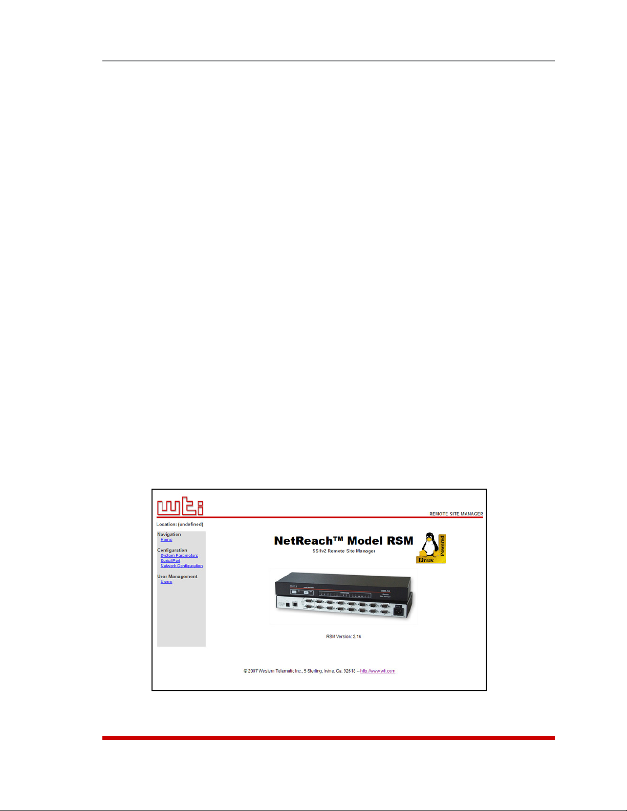
3.2. The Home Screen - Web Interface
4.1. Terminal Block Assembly (DC Units Only)
5.1. The Port Status Screen (Text Interface; RSM-8 Shown) . . . . . . . . . . . . . . . . . . . . . . . . . . .
5.2. The Home Screen (Web Browser Interface) . . . . . . . . . . . . . . . . . . . . . . . . . . . . . . . . . . . .
5.3. The System Parameters Menu (Text Interface) . . . . . . . . . . . . . . . . . . . . . . . . . . . . . . . . . .
5.4. The System Configuration Menu (Web Browser Interface)
5.5. The Add User Menu (Text Interface; RSM-8 Shown)
5.6. The Add User Menu (Web Browser Interface; RSM-8 Shown) . . . . . . . . . . . . . . . . . . . . .
5.7. Port Configuration Menu (Text Interface)
5.8. Port Configuration Menu (Web Browser Interface) . . . . . . . . . . . . . . . . . . . . . . . . . . . . . .
5.9. Network Parameters Menu (Supervisor Mode Only)
5.10. Network Configuration Menu (Web Browser Interface)
5.11. Network Parameters Menu (Web Browser Interface) . . . . . . . . . . . . . . . . . . . . . . . . . . . .
5.12. Network Port Parameters Menu (Web Browser Interface)
5.13. IP Security Menu (Text Interface)
5.14. IP Security Menu (Web Browser Interface) . . . . . . . . . . . . . . . . . . . . . . . . . . . . . . . . . . . .
5.15. Static Route Menu (Text Interface) . . . . . . . . . . . . . . . . . . . . . . . . . . . . . . . . . . . . . . . . . . 5-34
5.16. Static Route Menu (Web Browser Interface) . . . . . . . . . . . . . . . . . . . . . . . . . . . . . . . . . . .
5.17. Nomain Name Server Menu (Text Interface) . . . . . . . . . . . . . . . . . . . . . . . . . . . . . . . . . . . 5-35
5.18. Domain Name Server Menu (Web Browser Interface) . . . . . . . . . . . . . . . . . . . . . . . . . . .
5.19. SNMP Access Menu (Text Interface) . . . . . . . . . . . . . . . . . . . . . . . . . . . . . . . . . . . . . . . . . 5-36
5.20. SNMP Trap Menu (Text Interface) . . . . . . . . . . . . . . . . . . . . . . . . . . . . . . . . . . . . . . . . . . . 5-36
5.21. SNMP Parameters Menu (Web Browser Interface)
5.22. LDAP Parameters Menu (Text Interface) . . . . . . . . . . . . . . . . . . . . . . . . . . . . . . . . . . . . . .
5.23. LDAP Parameters Menu (Web Browser Interface)
5.24. LDAP Group Configuration (Text Interface)
5.25. Add LDAP Group Menu (Text Interface
5.26. Add LDAP Group Menu (Web Browser Interface
5.27. View LDAP Group Menu (Text Interface
5.28. View LDAP Group Menu (Web Browser Interface
5.29. Modify LDAP Group Menu (Text Interface
5.30. Modify LDAP Group Menu (Web Browser Interface
5.31. Delete LDAP Group Menu (Web Browser Interface)
5.32. LDAP Kerberos Set Up Menu (Text Interface
5.33. LDAP Kerberos Set Up Menu (Web Browser Interface) . . . . . . . . . . . . . . . . . . . . . . . . . . 5-45
5.34. The TACACS Parameters Menu (Text Interface) . . . . . . . . . . . . . . . . . . . . . . . . . . . . . . . .
5.35. The TACACS Parameters Menu (Web
5.36. The RADIUS Parameters Menu (Text Interface)
5.37. The RADIUS Parameters Menu (Web
5.38. The Copy Port Parameters Menu
6.1. Port Status Screen (Sample Data Shown - RSM-8 Unit Shown)
6.2. Port Diagnostics Screen (RSM-8 Shown) . . . . . . . . . . . . . . . . . . . . . . . . . . . . . . . . . . . . . .
6.3. Network Status Screen . . . . . . . . . . . . . . . . . . . . . . . . . . . . . . . . . . . . . . . . . . . . . . . . . . . .
6.4. Port Parameters Screen (RS232 Port Shown)
6.5. Port Parameters Screen (Network Port Shown) . . . . . . . . . . . . . . . . . . . . . . . . . . . . . . . . .
9.1. The Test Menu (Text Interface, Supervisor Mode Only)
A.1. RS232 Port Interface
Table of Contents
2-2
2-2
2-2
3-3
. . . . . . . . . . . . . . . . . . . . . . . . . . . . . . . . . . . . . . . . . . . 3-3
. . . . . . . . . . . . . . . . . . . . . . . . . . . . . . . . . . . . . 4-1
5-2
5-3
5-5
. . . . . . . . . . . . . . . . . . . . . . . . 5-5
. . . . . . . . . . . . . . . . . . . . . . . . . . . . 5-14
5-14
. . . . . . . . . . . . . . . . . . . . . . . . . . . . . . . . . . . . . 5-18
5-18
. . . . . . . . . . . . . . . . . . . . . . . . . . . . 5-24
. . . . . . . . . . . . . . . . . . . . . . . . . . 5-24
5-26
. . . . . . . . . . . . . . . . . . . . . . . . 5-27
. . . . . . . . . . . . . . . . . . . . . . . . . . . . . . . . . . . . . . . . . . . 5-29
5-29
5-34
5-35
. . . . . . . . . . . . . . . . . . . . . . . . . . . . . 5-36
5-38
. . . . . . . . . . . . . . . . . . . . . . . . . . . . . . 5-38
. . . . . . . . . . . . . . . . . . . . . . . . . . . . . . . . . . . 5-40
; RSM-8 Shown) . . . . . . . . . . . . . . . . . . . . . . . . . 5-41
; RSM-8 Shown) . . . . . . . . . . . . . . . . . . 5-41
; RSM-8 Shown) . . . . . . . . . . . . . . . . . . . . . . . . . 5-42
; RSM-8 Shown) . . . . . . . . . . . . . . . . . 5-42
; RSM-8 Shown) . . . . . . . . . . . . . . . . . . . . . . . 5-43
; RSM-8 Shown) . . . . . . . . . . . . . . . . 5-43
. . . . . . . . . . . . . . . . . . . . . . . . . . . . 5-44
) . . . . . . . . . . . . . . . . . . . . . . . . . . . . . . . . . . 5-45
5-47
Browser Interface) . . . . . . . . . . . . . . . . . . . . . . . . 5-47
. . . . . . . . . . . . . . . . . . . . . . . . . . . . . . . . 5-49
Browser Interface) . . . . . . . . . . . . . . . . . . . . . . . . 5-49
. . . . . . . . . . . . . . . . . . . . . . . . . . . . . . . . . . . . . . . . . . . 5-51
. . . . . . . . . . . . . . . . . . . . 6-2
6-3
6-4
. . . . . . . . . . . . . . . . . . . . . . . . . . . . . . . . . . 6-5
6-5
. . . . . . . . . . . . . . . . . . . . . . . . . . . 9-3
. . . . . . . . . . . . . . . . . . . . . . . . . . . . . . . . . . . . . . . . . . . . . . . . . . . Apx-1
vii
Page 9

1. Introduction
The RSM-8, RSM-16, RSM-16DC, RSM-32 and RSM-32DC Remote Site Managers
provide in-band and out-of-band access to RS-232 console ports and maintenance
ports on UNIX servers, routers and any other network element that includes a serial
console port. System administrators can access the RSM via TCP/IP network, using
SSH or Telnet, or out-of-band via modem or local terminal. The RSM features two
separate command interfaces; a convenient, user-friendly web browser interface, and a
simple, command driven text interface.
Intelligent Port Selection
Each of the RSM’s RS232 serial ports can be individually accessed by number, name or
group via SSH or Telnet sessions. The RSM also allows direct connections using TCP
port assignments. Each RSM serial port can be separately configured using simple
menu driven commands to set the port password, data rate, flow control and other
operating parameters.
The full matrix capability of the RSM allows you to easily connect any two ports on the
switch, even when the ports are using different communications settings. Ports can
also be connected or disconnected by a third party with supervisor rights, and system
managers can swap various RS232 devices between ports at a remote location.
Security and Collocation Features
Secure Shell (SSHv2) encryption and address-specific IP security masks prevent
unauthorized access to command and configuration functions. The RSM also provides
two different levels of user security; the Supervisor level and the Non-Supervisor
level. The Supervisor level, which is intended for use by system managers and other
administrators, provides complete access to all RSM port connection / disconnection
functions, operating features and configuration menus, and also allows access to
any port on the switch. The Non-Supervisor level is ideal for collocation applications,
since users are only permitted to view status and connect to the ports allowed by their
password.
Capture Buffer
"Buffer Mode" allows individual ports to capture and store incoming data, such as error
and status messages received from attached console ports. This "snapshot" of the last
data received is stored in memory, and can be viewed, saved, or erased by the system
operator at any time. Console messages can be stored in the RSM port buffers, and
sent to a remote location via SYSLOG, or an SNMP message can be generated to alert
administrators when new console messages are received.
1-1
Page 10

Configuration Backup
Once you have configured the RSM to fit your application, parameters and options
can be saved to an ASCII text file on your PC. This allows you to quickly restore userselected parameters if unit configuration is accidentally altered or deleted. Saved
parameters can also be uploaded to other RSM units. This allows rapid set-up when
several units will be configured with identical or similar parameters.
RSM-8, RSM-16, RSM-16DC, RSM-32 and RSM-32DC Units
This User’s Guide discusses five different models from our RSM product line: the
RSM-8, RSM-16, RSM-16DC, RSM-32 and the RSM-32DC. Throughout this User's
Guide, all of these units are referred to as the "RSM." Note however that these units
differ as described below:
• RSM-8: 8 Serial Ports, 100 to 240 VAC, 50/60 Hz, 5 Watts
• RSM-16: 16 Serial Ports, 100 to 240 VAC, 50/60 Hz, 5 Watts
• RSM-16DC: 16 Serial Ports, -48 VDC
• RSM-32: 32 Serial Ports, 100 to 240 VAC, 50/60 Hz, 5 Watts
• RSM-32DC: 32 Serial Ports, -48 VDC.
Aside from the differences listed above, all other features function identically in all five
models.
Introduction
Typographic Conventions
^ (e.g. ^X) Indicates a control character. For example, the text
"^X" (Control X) indicates the [Ctrl] key and the [X]
key must be pressed simultaneously.
COURIER FONT Indicates characters typed on the keyboard.
For example, /E or /P 02.
[Bold Font] Text set in bold face and enclosed in square brackets,
indicates a specific key.
For example, [Enter] or [Esc].
< > Indicates required keyboard entries:
For Example: /P <n>.
[ ] Indicates optional keyboard entries.
For Example: /W [n].
1-2
Page 11
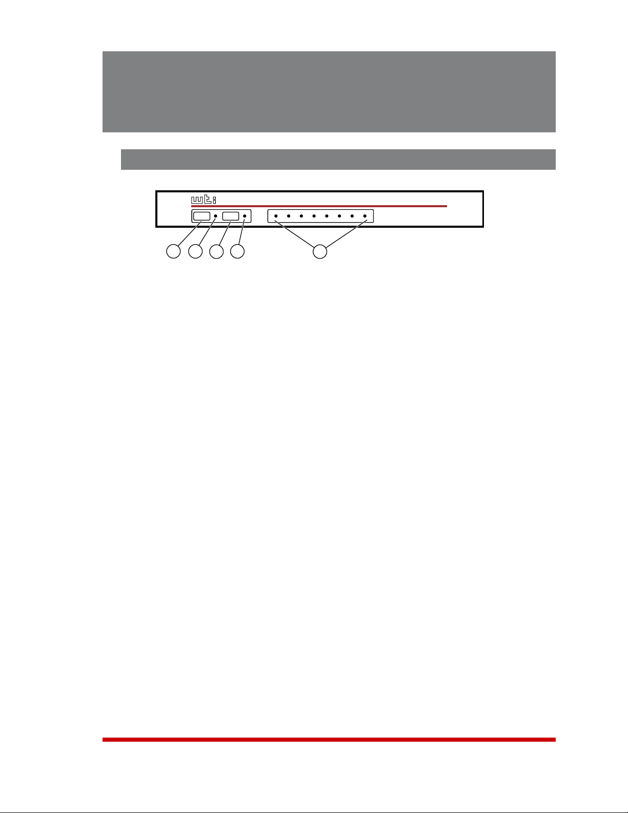
CLEAR
SET
ON
RDY
CONNECTIONS
1
2 3
4
5
6
7 8
www.wti.com
RSM-8
Remote
Site Manager
1
2
3
4
5
2. Unit Description
2.1. Front Panel
Figure 2.1: Instrument Front Panel (Model RSM-8 Shown)
CLEAR: Restarts the RSM without changing user-selected parameter settings.
Note: When Clear is pressed, all ports will be disconnected.
ON: Lights when AC Power is applied.
SET: Used to Initialize the RSM to default parameters. To initialize the RSM, press
and hold the SET button for approximately five seconds.
• During initialization, all port LEDs will flash ON three times.
• After initialization, all command-selected parameters will be cleared, and the
RSM will revert to the default parameters. The default "super" user account
will also be restored.
Notes:
RDY: (Ready) Flashes to indicate unit is operational.
ACTIVITY LEDs: A series of LEDs, which light to indicate data activity at the
corresponding port.
• RSM-8 units include 8 Activity LEDs
• RSM-16 and RSM-16DC units include 16 Activity LEDs
• RSM-32 and RSM-32DC units include 32 Activity LEDs.
2-1
Page 12

O
I
PHONE
LINE
10/100BaseT
LINK
ACTIVITY
SYSTEM SETUP PORTS
(DTE)
1 2 3 4 5 6 7 8
1
2
3
4
5
O
I
PHONE
LINE
10/100BaseT
LINK
ACTIVITY
2
1
3
4
5
6
7
8
9
10
11
12
13
14
15
16
SYSTEM
SETUP
PORTS
(DTE)
1
2
3
3
4
5
PHONE
LINE
10/100BaseT
LINK
ACTIVITY
2
1
3
4
5
6
7
8
9
10
11
12
13
14
15
16
18
17
19
20
21
22
23
24
25
26
27
28
29
30
31
32
SYSTEM
SETUP
PORTS
(DTE)
1
2
3
3
4
5
2.2. Back Panel
As shown in Figures 2.2, 2.3 and 2.4, the RSM Back Panel includes the following
components:
Phone Line Port: For connection to your external phone line.
Network Port: An RJ45 Ethernet port for connection to your 10/100Base-T, TCP/IP
network. Note that the RSM features a default IP address (192.168.168.168). This
allows you to connect to the unit without first assigning an IP address. Note that the
Network Port also includes two, small LED indicators for Link and Data Activity. For
more information on Network Port configuration, please refer to Section 5.8.
Unit Description
Figure 2.2: Instrument Back Panel (Model RSM-8)
Figure 2.3: Instrument Back Panel (Model RSM-16)
Figure 2.4: Instrument Back Panel (Model RSM-32)
2-2
Page 13

Unit Description
RS232 Serial Ports: For connection to console ports on target devices. Standard
DB9 connectors configured as DTE ports. The RS232 ports are similar to a serial
port on a PC. When connecting a modem, use a standard serial cable. When
connecting a PC or other DTE device use a null modem cable.
• RSM-8 units include 8 Serial Ports.
• RSM-16 and RSM-16DC units include 16 Serial Ports.
• RSM-32 and RSM-32DC units include 32 Serial Ports.
Power Inlet: An IEC-320-C14 inlet, for connection to your 100 to 240 VAC power
supply. Note that RSM-16DC and RSM-32DC units (-48 VDC powered models)
include a terminal block assembly (see Figure 4.1) in place of the power inlet. For
more information, please refer to Section 4.1.
Power On/Off Switch
2-3
Page 14

3. Getting Started
This section describes a simplified installation procedure for our RSM-8, RSM-16,
RSM-16DC, RSM-32 and RSM-32DC models, which will allow you to communicate with
the unit in order to demonstrate basic features and check for proper operation.
Note that this Quick Start Guide does not provide a detailed description of unit
configuration, or discuss advanced operating features in detail. In order to take full
advantage of the features provided by this unit, it is recommended that you should
complete the entire Installation and Configuration sections after performing this Quick
Start procedure.
3.1. Quick Hardware Installation
3.1.1. Apply Power to the RSM
Refer to the safety precautions listed at the beginning of this User’s Guide and in
Section 4, and then connect the unit to an appropriate power source. Note that RSM-8,
RSM-16 and RSM-32 units are designed for 100 to 240 VAC, 50/60 Hz operation and
feature an auto sensing power supply; while RSM-16DC and RSM-32DC models are
designed for -48 VDC operation.
When power is applied to the RSM, the ON LED should light, and the RDY LED should
begin to flash. Note however, that the boot up procedure may take up to two minutes;
this delay is due to the time required to generate SSH keys.
3.1.2. Connect your Control Device to the RSM
The RSM can either be controlled via local PC Serial Port, modem, or TCP/IP network.
In order to connect ports or select parameters, commands are issued to the RSM via
either the Network Port, Modem or RS232 Setup Port. Note that it is not necessary to
connect to both the Network and Setup Ports, and that the Setup Port can be connected
to either a local PC or an external modem.
• Network Port: Connect your 10Base-T or 100Base-T network interface to the RSM
10/100Base-T Network port.
• Console Port: Use the supplied null modem cable to connect your PC COM port
to the RSM Set-Up Port (RS232).
• Modem: Connect your phone line to the RSM’s Phone Line (Modem) port.
3-1
Page 15

Getting Started
3.2. Communicating with the RSM
When properly installed and configured, the RSM will allow command mode access
via Telnet, Web Browser, SSH client, modem, or local PC. However, in order to ensure
security, both Telnet and Web Browser access are disabled in the default state. To
enable Telnet and/or Web Browser access, please refer to Section 5.8.
Notes:
• Default RSM serial port parameters are set as follows: 9600 bps, RTS/
CTS Handshaking, 8 Data Bits, One Stop Bit, No Parity. Although these
parameters can be easily redefined, for this Quick Start procedure, it is
recommended to configure your communications program to accept the
default parameters.
• The RSM features a default IP Address (192.168.168.168) and a default
Subnet Mask (255.255.255.0.) This allows network access to command
mode, providing that you are contacting the RSM from a node on the same
subnet. When attempting to access the RSM from a node that is not on the
same subnet, please refer to Section 5.8 for further configuration instructions.
1. Access Command Mode: The RSM includes two separate user interfaces; the Text
Interface and the Web Browser Interface. The Text Interface is available via Local
PC, SSH Client, Telnet, or Modem and can be used to both configure the RSM and
create connections between ports. The Web Browser interface is only available
via TCP/IP network, and can be used to configure the unit, but cannot create port
connections.
a) Via Local PC: Start your communications program and then press [Enter].
b) Via SSH Client: Start your SSH client, enter the default IP address
(192.168.168.168) for the RSM and invoke the connect command.
c) Via Web Browser: Make certain that Web Browser access is enabled as
described in Section 5.8. Start your JavaScript enabled Web Browser, enter
the default RSM IP address (192.169.168.168) in the Web Browser address bar,
and then press [Enter].
d) Via Telnet: Make certain that Telnet access is enabled as described in
Section 5.8.1. Start your Telnet client, and enter the RSM's default IP address
(192.168.168.168).
e) Via Modem: Use your communications program to dial the number for the line
connected to the RSM’s Phone Line port.
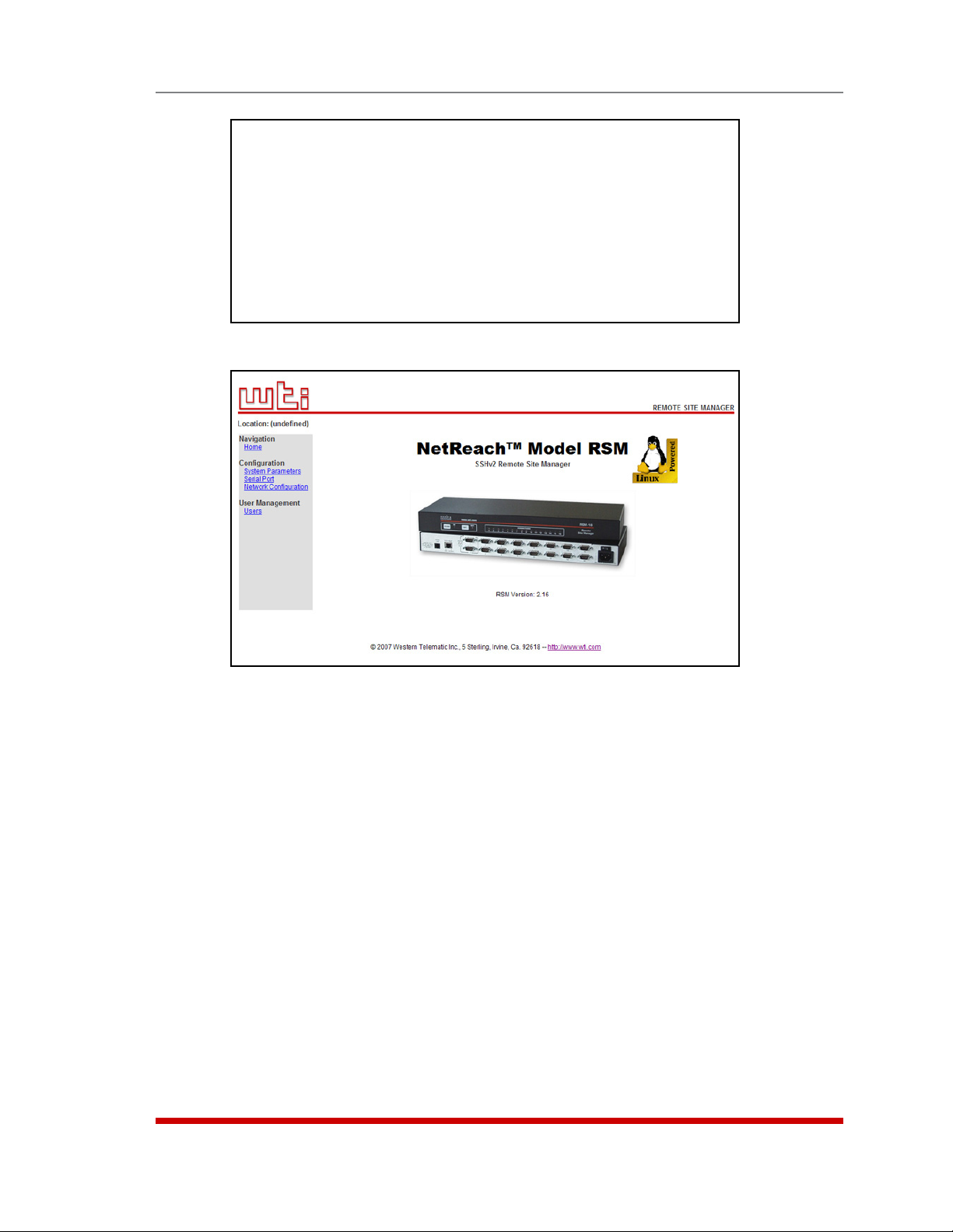
2. Username / Password Prompt: A message will be displayed, which prompts you
to enter your username (Login) and password.. The default username is "super"
(all lower case, no quotes), and the default password is also "super". If a valid
username and password are entered, the RSM will display either the Home Screen
(Web Browser Interface) or the Port Status Screen (SSH, Telnet, or Modem) as
shown in Figure 3.1 and Figure 3.2.
3-2
Page 16
PORT STATUS:
Site ID: (undefined) 02/07/2007 00:23:39 GMT (GMT+0000)
PORT | NAME | USERNAME | STATUS | MODE | BUFFER COUNT
-----+------------------+------------------+--------+--------+------------- 01 | (undefined) | | Free | Any | 0
02 | (undefined) | | Free | Any | 0
03 | (undefined) | | Free | Pass | 0
04 | (undefined) | | Free | Pass | 0
05 | (undefined) | | Free | Pass | 0
06 | (undefined) | | Free | Pass | 0
07 | (undefined) | | Free | Pass | 0
08 | (undefined) | | Free | Pass | 0
09 | MODEM | | Free | Modem | 0
Enter /H for command menu.
RSM>
Figure 3.1: The Port Status Screen - Text Interface (RSM-8 Shown)
Getting Started
Figure 3.2: The Home Screen - Web Interface
3. Review Help Menu: If you are communicating with the RSM via the text interface
(SSH, Telnet or Modem), type /H and press [Enter] to display the Help Menu,
which lists all available RSM commands. Note that the Help Menu is not available
via the Web Browser Interface.
4. Creating Connections Between Ports: The RSM can perform two types of
connections; Resident Connections and Third Party Connections. Note that Port
Connection commands are only available via the Text Interface, and cannot be
invoked via the Web Browser Interface.
a) Resident Connection: Your resident port (e.g. Port 1) issues a /C command to
connect to a second port.
i. To connect Port 1 to Port 2, type /C 2 [Enter]. While Port 1 is connected,
the RSM will not recognize commands issued at Port 1. However, the unit
will recognize a Resident Disconnect Sequence issued at Port 1 or Port 2.
ii. Issue the Resident Disconnect Sequence (Logoff Sequence); type ^X
(press [Ctrl] and [X] at the same time).
3-3
Page 17

Getting Started
b) Third Party Connection: Your resident port (e.g. Port 1) issues a /C command
to create a connection between two other ports.
i. To connect Port 2 to Port 3, type /C 2 3 [Enter].
ii. While Ports 2 and 3 are connected, Port 1 will still recognize RSM
commands. Type /S [Enter] to display the Port Status Screen. The
"STATUS" column should now list Ports 2 and 3 as connected, and Port 1
as "Free".
iii. Issue a Third Party Disconnect command to disconnect Ports 2 and 3; type
/D 2 [Enter]. The unit will display the "Are you Sure (y/n)?" prompt. Type
y and press [Enter] to disconnect.
iv. Type /S [Enter] to display the Port Status Screen. The Status screen
should now list Ports 2 and 3 as "Free".
5. Exit Command Mode: When you finish communicating with the unit via the text
interface, it is important to always log off using the appropriate RSM command,
rather than by simply closing your Telnet program. When you log off using the
proper command, this ensures that the unit has completely exited from command
mode, and is not waiting for the inactivity timeout to elapse before allowing
additional connections. To exit command mode, type /X and press [Enter].
This completes the RSM Quick Start procedure. Prior to placing the unit into operation,
it is recommended to refer to the remainder of this User’s Guide for important
information regarding advanced configuration capabilities and more detailed operation
instructions. If you have further questions regarding the RSM unit, please contact WTI
Customer Support as described in Appendix C.
3-4
Page 18
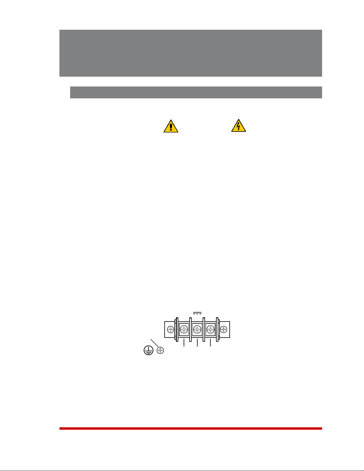
-48V 0.1A
0
-48V
A
-48V
B
GROUND
SCREW
4. Hardware Installation
4.1. Connecting Power to the RSM Unit
The RSM is available in both AC and DC powered versions. When connecting AC or DC
power to the RSM, proceed as follows:
• Before attempting to install this unit, please review the warnings and
cautions listed at the front of the user's guide.
• This device should only be operated with the type of power source
indicated on the instrument nameplate. If you are not sure of the type
of power service available, please contact your local power company.
• Reliable earthing (grounding) of this unit must be maintained.
Particular attention should be given to supply connections when
connecting to power strips, rather than directly to the branch circuit.
4.1.1. AC Powered Units
Plug the power cable (supplied with the unit) into the receptacle on the RSM back panel.
Then, connect the power cable to an appropriate, grounded outlet. The RSM features
a self adjusting power supply that automatically adapts to power supplies between 90
and 250 VAC. Press the Power Switch ON. The ON LED should light and the RDY LED
should begin to flash.
CAUTIONS:
4.1.2. DC Powered Units
When connecting the RSM to your DC Power source, first remove the protective cover
from the terminal block, attach the wires from the -48 VDC power source to the screw
terminals, connect the ground line to the labeled ground screw, and then replace the
protective cover.
Figure 4.1: Terminal Block Assembly (DC Units Only)
4-1
Page 19

Hardware Installation
4.2. Connecting the Network Cable
The Network Port is an RJ45, 10/100BaseT Ethernet Jack, for connection to a TCP/IP
network. Note that the RSM features a default IP Address (192.168.168.168.) Providing
that you are communicating with the unit from a node on the same subnet, this allows
you to contact the RSM without first accessing command mode to assign an IP address.
When installing the RSM in a working network environment, it is recommended to
assign the IP Address, Gateway Address, and Subnet Mask as described in Section 5.8.
4.3. Connecting Devices to the RSM
1. Determine which RSM port will be used for connection to the new device
(e.g. Port 3).
2. Use an appropriate DB9 cable to connect the RS232 serial port on the device to a
DB9 port on the RSM.
a) External Modems and other DCE Devices: Use a standard serial
modem cable.
b) PCs and other DTE Devices: Use a null modem cable.
3. Access the RSM command mode and select communication parameters for each
RSM port as described in Section 5.7.
4-2
Page 20

5. Configuration
5.1. Communicating with the RSM Unit
In order to configure the RSM, you must first connect to the unit, and access command
mode. Note that, the RSM offers two separate configuration interfaces; the Web
Browser Interface and the Text Interface.
In addition, the RSM also offers three different methods for accessing command mode;
via network, via modem, or via local console. The Web Browser interface is only
available via network, and the Text Interface is available via network (SSH or Telnet),
modem or local PC.
5.1.1. The Text Interface
The Text Interface consists of a series of simple ASCII text menus, which allow you to set
options and define parameters by entering the number for the desired option using your
keyboard, and then typing in the value for that option.
Since the Web Browser Interface and Telnet accessibility are both disabled in the
default state, you will need to use the Text Interface to contact the unit via Local PC or
SSH connection when setting up the unit for the first time. After you have accessed
command mode using the Text Interface, you can then enable Web Access and
Telnet Access in order to allow future communication with the unit via Web Browser or
Telnet. You will not be able to contact the unit via Web Browser or Telnet until you have
specifically enabled those options.
Once Telnet Access is enabled, you will then be able to use the Text Interface to
communicate with the RSM via local PC, Telnet or SSH connection. You can also use
the text interface to access command mode via the RSM's internal modem, or via an
external modem installed at one of the RSM's RS232 serial ports.
In order to use the Text Interface, your installation must include:
• Access via Network: The RSM must be connected to your TCP/IP Network, and
your PC must include a communications program (such as HyperTerminal.)
• Access via Modem: A phone line must be connected to the RSM's Phone Line
port, and your PC must include a communications program.
• Access via Local PC: Your PC must be physically connected to one of the
RSM’s RS232 ports as described in Section 4.3, and your PC must include a
communications program.
5-1
Page 21

Configuration
To access command mode via the Text Interface, proceed as follows:
Note: Command mode cannot be accessed via a Buffer Mode Port, Passive
Mode Port, or any port that is presently connected to another RSM port.
1. Contact the RSM Unit:
a) Via Local PC: Start your communications program and press [Enter]. Wait
for the connect message, then proceed to Step 2.
b) Via Network: The RSM includes a default IP address (192.168.168.168) and a
default subnet mask (255.255.255.0.) This allows you to contact the unit from
any network node on the same subnet, without first assigning an IP Address to
the unit. For more information, please refer to Section 5.8.
i. Via SSH Client: Start your SSH client, and enter the RSM’s IP Address.
Invoke the connect command, wait for the connect message, then
proceed to Step 2.
ii. Via Telnet: Start your Telnet Client, and then Telnet to the RSM’s IP
Address. Wait for the connect message, then proceed to Step 2.
Note: When communicating with the unit for the first time, you will not be able
to contact the unit via Telnet, until you have accessed command mode, via
Local PC or SSH Client, and used the Network Parameters Menu (/N) to enable
Telnet as described in Section 5.8.
c) Via Modem: Use your communications program to dial the number for the line
connected to the RSM’s Phone Line port.
2. Login / Password Prompt: A message will be displayed, which prompts you to
enter a username (login name) and password. The default username is "super" (all
lower case, no quotes), and the default password is also "super".
PORT STATUS:
Site ID: (undefined) 02/07/2007 00:23:39 GMT (GMT+0000)
PORT | NAME | USERNAME | STATUS | MODE | BUFFER COUNT
-----+------------------+------------------+--------+--------+------------- 01 | (undefined) | | Free | Any | 0
02 | (undefined) | | Free | Any | 0
03 | (undefined) | | Free | Pass | 0
04 | (undefined) | | Free | Pass | 0
05 | (undefined) | | Free | Pass | 0
06 | (undefined) | | Free | Pass | 0
07 | (undefined) | | Free | Pass | 0
08 | (undefined) | | Free | Pass | 0
09 | MODEM | | Free | Modem | 0
Enter /H for command menu.
RSM>
Figure 5.1: The Port Status Screen (Text Interface; RSM-8 Shown)
5-2
Page 22
Configuration
3. If a valid username and password are entered, the RSM will display the Port Status
Screen, shown in Figure 5.1.
Note: If the Telnet connection is refused, it is most likely due to one of the
following reasons:
• The IP Security feature has denied the connection.
• You are attempting to use an account that permits Supervisor commands to
connect to a port that does not permit
Supervisor Commands.
5.1.2. The Web Browser Interface
The Web Browser Interface consists of a series of web forms, which can be used
to select configuration parameters and enable/disable RSM operating functions, by
clicking on radio buttons and/or entering text into designated fields.
Notes:
• The Web Browser Interface cannot be used to connect and disconnect ports;
the Web Browser Interface is used only for configuration purposes.
• In order to use the Web Browser Interface, Web Access must be enabled
via the Text Interface Network Parameters Menu (/N), the RSM must be
connected to a TCP/IP network, and your PC must be equipped with a
JavaScript enabled web browser.
1. Start your JavaScript enabled Web Browser, key the RSM’s IP address (default =
192.168.168.168) into the web browser’s address bar, and press [Enter].
2. Username / Password Prompt: A message box will prompt you to enter your
username and password. The default username is "super" (all lower case, no
quotes), and the default password is also "super".
3. If a valid username and password are entered, the RSM Home Screen will appear
as shown in Figure 5.2.
Figure 5.2: The Home Screen (Web Browser Interface)
5-3
Page 23

Configuration
5.2. System SetUp Ports
Serial Ports 1 and 2 are reserved as SetUp Ports, and will always permit password
protected access to Supervisor commands. Therefore, Ports 1 and 2 cannot be
configured as Buffer Mode Port or Passive Mode Ports, because these port modes do
not permit access to command mode. In addition, the Supervisor Mode cannot be
disabled at Ports 1 and 2.
5.3. Configuration Menus
Although the Web Browser Interface and Text Interface provide two separate means for
selecting parameters, both interfaces allow access to the same set of basic parameters,
and parameters selected via one interface will also be applied to the other. To access
the configuration menus, proceed as follows:
• Text Interface: Refer to the Help Screen (/H) and then enter the appropriate
command to access the desired menu. When the configuration menu appears, key
in the number for the parameter you wish to define, and follow the instructions in
the resulting submenu.
• Web Browser Interface: Click the appropriate button on the left hand side of the
Home Screen (Figure 5.2) to access the desired configuration menu. To change
parameters, click in the desired field and key in the new value or select a value from
the pull-down menu. To apply newly selected parameters, click on the "Change
Parameters" button at the bottom of the menu or the "Set" button next to the field.
The following sections describe options and parameters that can be accessed via each
of the configuration menus. Please note that essentially the same set of parameters and
options are available to both the Web Browser Interface and Text Interface.
Note: Configuration menus are only available when you have logged into
command mode using a password and port that permit Supervisor Level
commands.
5-4
Page 24
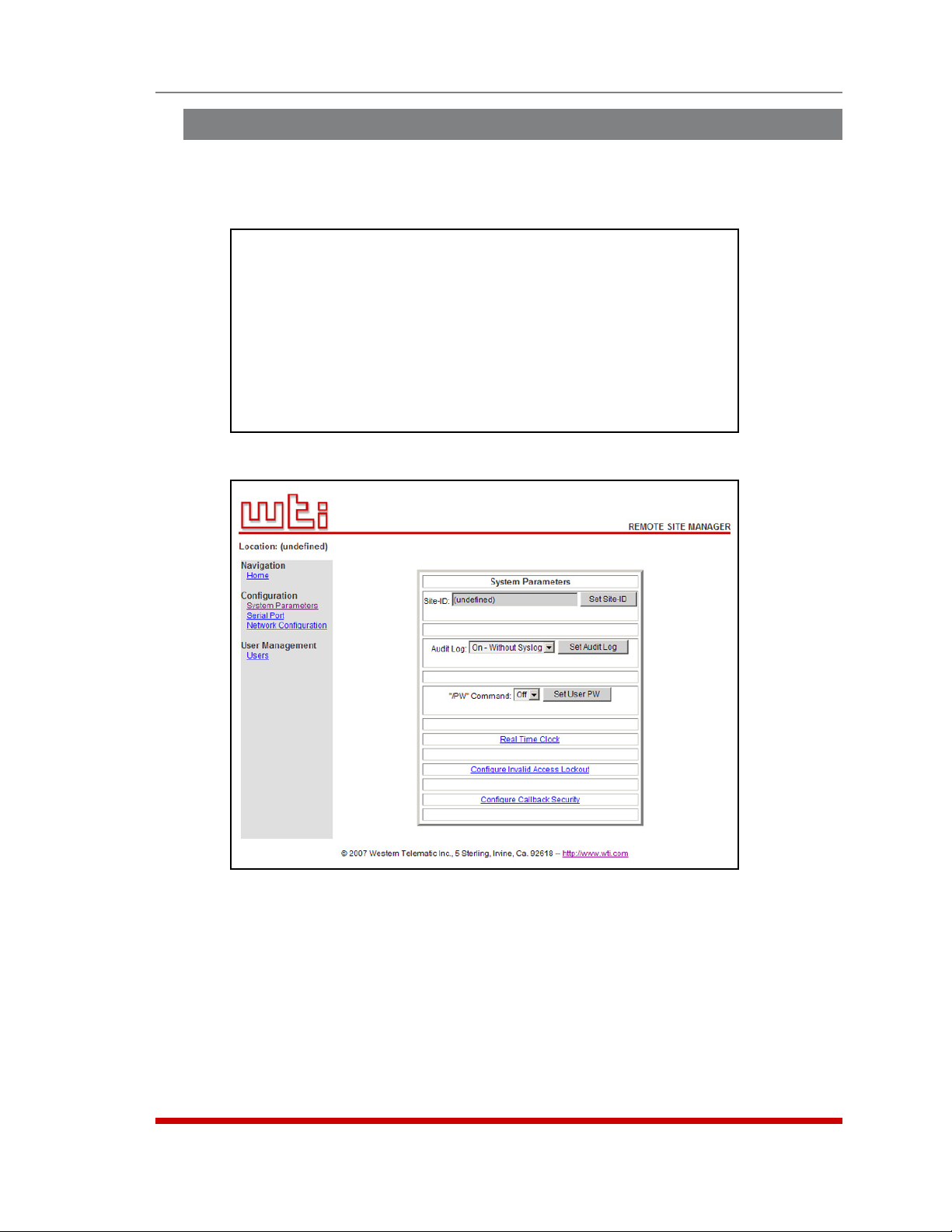
5.4. Defining System Parameters
The System Parameters menus are used to define the Site ID Message, set the system
clock and calendar, and configure the Invalid Access Lockout feature and Callback
feature.
SYSTEM PARAMETERS:
1. User Directory
2. Site-ID:
3. Real Time Clock: 01/09/2007 00:26:06
4. Invalid Access Lockout: On
5. Audit Log: On - Without Syslog
6. Callback Security: On - Callback (Without Password Prompt)
7. “/PW” Command: Off
Enter: #<CR> to change,
<ESC> exit ...
Figure 5.3: The System Parameters Menu (Text Interface)
Configuration
Figure 5.4: The System Configuration Menu (Web Browser Interface)
5-5
Page 25

Configuration
In the Text Interface, the System Parameters menu is also used to create and manage
user accounts and passwords. Note however, that when you are communicating with
the unit via the Web Browser Interface, accounts and passwords are managed and
created via a separate menu that is accessed by clicking on the "Users" link on the left
hand side of the menu.
• Text Interface: Type /F and press [Enter]. The System Parameters Menu will
appear as shown in Figure 5.3.
• Web Browser Interface: Click the "System Properties" link on the left hand side of
the RSM Home Screen. The System Parameters menu will be displayed as shown
in Figure 5.4.
The System Parameters Menus are used to define the following:
• User Directory: This function is used to create, modify and delete user accounts
and passwords. As discussed in Section 5.6, user accounts allow you to set the
security level for each password as well as determine which ports a user will be
allowed to access.
Note: The "User Directory" option does not appear in the Web Browser
Interface’s System Parameters menu, and is instead, accessed via the "Users"
link on the left hand side of each configuration menu.
• Site ID: A text field, generally used to note the installation site or name for the RSM
unit. (Up to 32 chars.; Default = undefined.)
Notes:
• The Site ID cannot include double quotes.
• The Site ID will be cleared if the RSM is reset to default settings.
• Real Time Clock: This prompt provides access to the Real Time Clock menu,
which is used to set the clock and calendar, and to enable and configure the NTP
(Network Time Protocol) feature as described in Section 5.4.1.
• Invalid Access Lockout: If desired, this feature can be used to automatically
disable an RSM serial port after a user specified number of unsuccessful login
attempts are made. For more information, please refer to Section 5.4.2.
• Audit Log: Enables and configures the Audit Log feature, as described in
Section 5.4.3. (Default = On - Without Syslog.)
• Callback Security: Enables / configures the Callback Security Function as
described in Section 5.4.4. In order for this feature to function, a Callback number
must also be defined for each desired user account as described in Section 5.6.
• "/PW" Command: Enables/Disables the /PW (Change Password) command.
When enabled, the /PW command can be issued at the text interface by any user
account in order to change that account’s password. When disabled, accounts
that do not permit Supervisor commands will not be able to change passwords.
(Default = Off.)
5-6
Page 26

Configuration
5.4.1. The Real Time Clock and Calendar
The Real Time Clock menu is used to set the RSM's internal clock and calendar. To
access the Real Time Clock Menu, proceed as follows:
• Text Interface: Type /F and press [Enter]. The System Parameters menu will
appear as shown in Figure 5.3. At the System Parameters menu, type 3 and press
[Enter] to display the Real Time Clock menu.
• Web Browser Interface: Click on the "System Properties" link at the left hand side
of the RSM Home Screen to display the System Parameters menu as shown in
Figure 5.4. From the System Parameters Menu, click on the "Real Time Clock" link
to access the Real Time Clock menu.
The configuration menu for the Real Time Clock offers the following options:
• Date: Sets the Month, Date, Year and day of the week for the RSM’s real-time
clock/calendar.
• Time: Sets the Hour, Minute and Second for the RSM’s real time clock/calendar.
Key in the time using the 24-hour (military) format.
• Time Zone: Sets the time zone, relative to Greenwich Mean Time. Note that the
Time Zone setting will function differently, depending on whether or not the NTP
feature is enabled and properly configured. (Default = GMT (No DST).)
◆
NTP Enabled: The Time Zone setting is used to adjust the Greenwich Mean
Time value (received from the NTP server) to determine the precise local time for
the selected time zone.
◆
NTP Disabled: If NTP is disabled, or if the RSM is not able to access the NTP
server, then status screens and activity logs will list the selected Time Zone and
current Real Time Clock value, but will not apply the correction factor to the
displayed Real Time Clock value.
• NTP Enable: When enabled, the RSM will contact an NTP server (defined via
the NTP IP Address prompts) once a day, and update its clock based on the NTP
server time and selected Time Zone. (Default = Off.)
Notes:
• The RSM will also contact the NTP server and update the time whenever you
change NTP parameters.
• To command the RSM to immediately contact the NTP server at any time,
make certain that the NTP feature is enabled and configured, then type /F
and press [Enter]. When the System Parameters menu appears, press
[Esc]. The RSM will save parameters and then attempt to contact the server,
as specified by currently defined NTP parameters.
• Primary NTP Address: Defines the IP address or domain name (up to 64
characters long) for the primary NTP server. (Default = undefined.)
5-7
Page 27

Configuration
• Secondary NTP Address: Defines the IP address or domain name (up to 64
characters long) for the secondary, fallback NTP Server. (Default = undefined.)
• NTP Timeout: The amount of time in seconds, that will elapse between each
attempt to contact the NTP server. When the initial attempt is unsuccessful, the
RSM will retry the connection four times. If neither the primary nor secondary NTP
server responds, the RSM will wait 24 hours before attempting to contact the NTP
server again. (Default = 3 Seconds.)
5.4.2. The Invalid Access Lockout Feature
When properly configured and enabled, the Invalid Access Lockout feature will watch all
login attempts made at all RSM ports. If a given port exceeds the selected number of
invalid attempts, then that port will be automatically disabled for a user-defined length of
time. The Invalid Access Lockout feature uses three separate counters to track invalid
access attempts:
• Serial Port Counter: Counts invalid access attempts at each individual serial port.
If the number of invalid attempts at a given port exceeds the user-defined Lockout
Attempts value, then that port will be locked.
• Raw Socket Counter: Counts invalid attempts to connect to a port via Raw Socket
protocol. If the number of invalid attempts at a given port exceeds the user-defined
Lockout Attempts value, then Raw Socket connections to that port will be locked.
• Telnet, SSH and Web Browser Counter: Counts all invalid attempts to access
command mode via Telnet, SSH or Web Browser interface. If the number of
cumulative invalid attempts exceeds the user-defined Lockout Attempts value, then
the Network Port will be locked.
Note that when an Invalid Access Lockout occurs, you can either wait for the Lockout
Duration period to elapse (after which, the RSM will automatically reactivate the port), or
you can issue the /UL command (type /UL and press [Enter]) via the Text Interface to
instantly unlock all RSM serial ports.
Notes:
• Invalid Access Lockout parameters, defined via the System Parameters
menu, will apply to all RSM serial ports.
• When a Port is locked, an external modem connected to that port will not
answer.
• When a given RSM serial port is locked, the other RSM serial ports will
remain unlocked, unless the Invalid Access Lockout feature has been
triggered at those other ports.
• If any one of the RSM’s logical network ports is locked, all other network
connections to the unit will also be locked.
• All invalid access attempts at the RSM Network Port are cumulative (the count
for invalid access attempts is determined by the total number of all invalid
attempts at all 64 logical network ports.) If a valid login name/password is
entered at any of the logical network ports, then the count for all RSM logical
network ports will be restarted.
• A Port that has been locked by the Invalid Access Lockout feature will still
respond to the ping command (providing that the ping command has not
been disabled.)
5-8
Page 28

Configuration
The Invalid Access menus allow you to select the following:
• Lockout Enable: Enables/Disables the Invalid Access Lockout feature. (Default =
On.)
• Lockout Attempts: The number of invalid attempts required to activate the Invalid
Access Lockout feature. (Default = 9.)
• Lockout Duration: The length of time ports will remain locked when an Invalid
Access Lockout occurs. If the duration is set at "Infinite", then ports will remained
locked until the /UL command is issued. (Default = 30 Minutes.)
5.4.3. The Audit Log
This feature allows you to create a record of command activity at all RSM ports. Audit
Log records will include the time, date, username, and a brief description of each
logged event (e.g., Connect, Login, etc.) The Audit Log is enabled and configured via
the System Parameters Menus as described in Section 5.4.
The System Parameters Menus includes three different options for Audit Log
configuration; Off (Audit Log disabled), "On with Syslog" and "On without Syslog." When
"On with Syslog" is selected, each individual Audit Log record will be sent out to the
user-defined Syslog IP Address as a Syslog message at the time that it is generated.
The Syslog IP Address is defined via the Network Parameters Menu, as described in
Section 5.8.
To read or erase the Audit Log, access command mode (via the Text Interface,) using an
account and port that permit Supervisor commands, type /A s, press [Enter] (where
s is an optional text string that you wish to search for,) and follow the instructions in the
resulting submenu. When the s (search string) option is included, the /A command will
return only those records that match the selected search string.
Notes:
• The RSM dedicates a fixed amount of internal memory for Audit Log records,
and if log records are allowed to accumulate until this memory is filled,
memory will eventually "wrap around," and older records will be overwritten
by newer records.
• The Audit Log cannot be viewed via the Web Browser Interface.
• When the
s option is used to search for all records that contain a specific text
string, the Delete function will still delete all Audit Log records; the Delete
function is not limited to the records that are currently displayed on screen.
5-9
Page 29

Configuration
5.4.4. Callback Security
The Callback function provides an additional layer of security when callers attempt to
access command mode via modem. When this function is properly configured, modem
users will not be granted immediate access to command mode upon entering a valid
password; instead, the unit will disconnect, and dial a user-defined number before
allowing access via that number. If desired, users may also be required to re-enter the
password after the RSM dials back.
In order for Callback Security to function properly, you must first enable and configure
the feature via the System Parameters menus as described in this section, and then
define a callback number for each desired user account as described in Section 5.6. To
configure and enable the Callback function, proceed as follows:
• Text Interface: Type /F and press [Enter] to access the System Parameters menu,
then type 6 and press [Enter] to display the Callback Security Menu.
• Web Browser Interface: Click the "System Properties" link on the left hand side
of the screen to access the System Configuration menu, then click the "Configure
Callback Security" link to display the Callback Security Menu.
In both the Text Interface and Web Browser Interface, the Callback Security Menu offers
the following options:
• Callback Enable: This prompt offers five different configuration options for the
Callback Security feature: (Default = On - Callback (Without Password Prompt.)
◆
Off: All Callback Security is disabled.
◆
On - Callback (Without Password Prompt): Callbacks will be performed for
user accounts that include a Callback Number, and the login prompt will not be
displayed when the user’s modem answers. If the account does not include a
Callback Number, that user will be granted immediate access and a Callback will
not be performed.
◆
On - Callback (With Password Prompt): Callbacks will be performed for user
accounts that include a Callback Number, and the login prompt will be displayed
when the user’s modem answers (accounts that include a Callback Number will
be required to re-enter their username/password when their modem answers.) If
the account does not include a Callback Number, then that user will be granted
immediate access and a Callback will not be performed.
5-10
Page 30

Configuration
◆
On - Callback ONLY (Without Password Prompt): Callbacks will be performed
for user accounts that include a Callback Number, and the username/password
prompt will not be displayed when the user’s modem answers. Accounts that do
not include a Callback Number will not be able to access command mode via an
RSM modem port.
◆
On - Callback ONLY (With Password Prompt): Callbacks will be performed
for user accounts that include a Callback Number, and the username/password
prompt will be displayed when the user’s modem answers (users will be required
to re-enter their username/password when their modem answers.) Accounts that
do not include a Callback Number will not be able to access command mode via
an RSM modem port.
• Callback Attempts: The number of times that the RSM will attempt to call the
Callback number. (Default = 3 attempts.)
• Callback Delay: The amount of time that the RSM will wait between Callback
attempts. (Default = 30 seconds.)
Notes:
• After configuring and enabling Callback Security, you must then define a
callback phone number for each desired user account (as described in
Section 5.6) in order for this feature to function properly.
• When using the "On - Callback (With Password Prompt)" option, it is
important to always define a callback number for each user account.
Otherwise accounts that do not include a callback number will be allowed to
immediately access command mode, and the callback function will not be
performed.
5-11
Page 31

Configuration
5.5. User Accounts
Prior to accessing command mode or establishing a Telnet Direct Connection, you will
be prompted to enter a username (login) and password. The username and password
entered at login determine which port(s) you will be allowed to connect and what type of
commands you will be allowed to execute. Each username / password combination is
defined within a "user account."
The RSM allows up to 128 user accounts; each account includes a username,
password, security level, port access rights, and an optional callback number.
5.5.1. Supervisor Access
In order to protect access to important command functions, the RSM allows you to
enable or disable Supervisor commands for specific accounts. Accounts that have
Supervisor Access enabled, will be allowed access to all configuration menus, review all
status screens, and connect to any RSM RS232 port.
When Supervisor Access is disabled, the account will be blocked from changing
configuration parameters, access to status screens will be restricted, and the user will
only be able to connect to ports specifically allowed by that account.
Note that in the default state, the RSM includes one predefined user account that
provides access to Supervisor commands and allows connections with any RSM RS232
port. The default username for this account is "super" (lowercase, no quotation marks),
and the password for the account is also "super".
Notes:
• In order to ensure security, it is recommended that when initially setting up
the unit, you should either change the username and password for the default
"super" user account, or preferably, a new user account with Supervisor
access should be created, and the "super" account should then be deleted.
• If the RSM is reset to default parameters, all user accounts will be cleared,
and the default "super" account will be restored.
• If Supervisor commands are disabled at a given port, then accounts that
permit Supervisor commands will not be able to access command mode via
that port.
In most cases, a password with Supervisor Access can be entered at any port, allowing
the user to invoke Supervisor level commands. However, if you wish to completely
deny a specific port’s access to Supervisor commands (even with a password that
normally permits them), the Port Parameters menus can disable Supervisor commands
at ports 3 and above, and the Network Port. The Supervisor Mode cannot be disabled
at Ports 1 and 2 (the System Setup Ports.) For a summary of commands and status
screens available to Supervisors and non-Supervisors, please refer to Section 13.
5.5.2. Port Access
Each account can be granted access to a different selection of ports. Accounts with
Supervisor access are always allowed to establish connections with all ports, but
accounts without Supervisor Access can be restricted to a specific port or group of
ports. Note also, that several accounts can be allowed access to the same port.
5-12
Page 32

5.6. Managing User Accounts
The User Directory function is employed to create new accounts, display parameters
for existing accounts, modify accounts and delete accounts. Up to 128 different user
accounts can be created. The "User Directory" function is only available when you
have logged into command mode using an account and port that permit Supervisor
commands.
• Text Interface: Type /F and press [Enter] to access the System Parameters Menu.
From the System Parameters Menu, type 1 and press [Enter] to access the User
Directory.
• Web Interface: Click the "Users" link on the left hand side of the screen to access
the User Directory management menus.
In both the Text Interface and the Web Browser Interface, the user configuration menu
offers the following functions:
• View User Directory: Displays currently defined parameters for any RSM user
account as described in Section 5.6.1.
• Add Username: Creates new user accounts, and allows you to assign a
username, password, command level, port access rights, and callback number, as
described in Section 5.6.2.
Configuration
• Modify User Directory: This option is used to edit or change account information,
as described in Section 5.6.3.
• Delete User: Clears user accounts, as described in Section 5.6.4.
5.6.1. Viewing User Accounts
The "View User Directory" option allows you to view details about each account,
including the ports the account is allowed to access and whether or not the account is
allowed to invoke Supervisor commands. The View User option will not display actual
passwords, and instead, the password field will read either "defined" or "undefined."
Note that the View User Accounts function is only available to users who have accessed
command mode using a password that permits Supervisor Level commands. To view
account details, proceed as follows:
• Text Interface: From the User Directory menu, type 1 and press [Enter]. The RSM
will display a screen which lists all defined user accounts. Key in the name of the
desired account and then press [Enter].
• Web Browser Interface: From the User menu, click the "View/Modify User"
link. The RSM will display a menu that allows you to select the desired user and
directory function. Select the "View User" button, and then click on the down arrow,
scroll to the desired username, select the username, and then click "Choose User."
5-13
Page 33

ADD USERNAME TO DIRECTORY:
1. Username:
2. Password: (undefined)
3. Supervisor Access: Off
4. Port Access:
PORT# PORT NAME ACCESS PORT# PORT NAME ACCESS
------------------------------- ------------------------------ 1 (undefined) Off 6 (undefined) Off
2 (undefined) Off 7 (undefined) Off
3 (undefined) Off 8 (undefined) Off
4 (undefined) Off 9 MODEM Off
5 (undefined) Off
5. Callback Phone #:
Enter: #<CR> to select,
<ESC> to return to previous menu ...
Figure 5.5: The Add User Menu (Text Interface; RSM-8 Shown)
Configuration
Figure 5.6: The Add User Menu (Web Browser Interface; RSM-8 Shown)
5.6.2. Adding User Accounts
The "Add Username" option allows you to create new accounts and assign usernames,
passwords, command level, port access rights, and Callback Numbers to each account.
Note that the Add User function is only available to users who have accessed command
mode using a password that permits Supervisor Level commands.
Notes:
• On RSM-8 units, the internal modem port is Port 9.
• On RSM-16 units, the internal modem port is Port 17.
• On RSM-32 units, the internal modem port is Port 33.
5-14
Page 34

Configuration
To create new user accounts, proceed as follows:
• Text Interface: From the User Directory menu, type 2 and press [Enter]. The Add
Username menu (Figure 5.5) will be displayed.
• Web Browser Interface: From the Edit User menu, click the "Add User" link. The
RSM will display the Add User menu (Figure 5.6.)
The Add Username Menu can be used to define the following parameters for each new
account:
• Username: Up to 32 characters long, and cannot include non-printable characters.
Duplicate usernames are not allowed. (Default = undefined.)
• Password: Five to sixteen characters long, and cannot include non-printable
characters. Note that passwords are case sensitive. (Default = undefined.)
• Supervisor Access: Determines whether the account is allowed to invoke
Supervisor commands. (Default = Off.)
• Port Access: Determines which port(s) this account will be allowed to create
connections with. (Default = All Ports Off.)
• Callback Number: Assigns a number that will be called when this user attempts
to access command mode via modem at an RSM port, where the Callback Security
Function has been enabled as described in Section 5.4.4. (Default = undefined.)
Notes:
• If the Callback Number is not defined, then Callbacks will not be performed
for this user.
• If the Callback Number is not defined for a given user, and the Callback
Security feature is configured to use either of the "On - Callback" options,
then this user will be granted immediate access to command mode via
modem.
• If the Callback Number is not defined for a given user, and the Callback
Security feature is configured to use the "On - Callback ONLY" option, then
this user will not be able to access command mode via a Modem Mode port.
5-15
Page 35

Configuration
5.6.3. Modifying User Accounts
The "Edit User Directory" function allows you to edit existing user accounts in order to
modify passwords and usernames, or change port access or Supervisor Command
capability. Note that the Edit/Modify User function is only available to users who have
accessed command mode using a password that permits Supervisor Level commands.
To modify a user account, proceed as follows:
• Text Interface: From the User Directory menu, type 3 and press [Enter]. The RSM
will display a screen which lists all user accounts. Key in the name of the account
you wish to modify, and press [Enter].
• Web Browser Interface: From the User Configuration menu, click the "View/Modify
User" link. The RSM will display a menu that allows you to select the user. Select
the "Modify User" button, then click the down arrow, scroll to the name of the
desired account, select the username, and then click "Choose User" to display the
"Modify User" menu.
5.6.4. Deleting User Accounts
This function is used to delete individual user accounts. Note that the Delete User
function is only available to users who have accessed command mode using a
password that permits Supervisor Level commands. To delete an existing user account,
proceed as follows:
• Text Interface: From the Users Directory menu, type 4 and press [Enter]. The
RSM will display a screen which lists all currently defined accounts. Key in the
name of the account you wish to delete and press [Enter]. The RSM will delete the
specified account without further prompting.
• Web Browser Interface: From the User Configuration menu, click the "View/Modify
Users" link. The RSM will display a menu that lists all currently defined accounts.
Select the "Delete User" box, then click the down arrow, scroll to the account you
wish to delete, select the account, and then click "Choose User." The RSM will
display a screen that lists details for the specified account; click "Delete User" to
confirm deletion.
Notes:
• Deleted accounts cannot be automatically restored.
• The RSM allows you to delete the default "super" account, which is included
to permit initial access to command mode. Before deleting the "super"
account, make certain to create another account that permits Supervisor
Access. If you do not retain at least one account with Supervisor Access,
you will not be able to invoke supervisor level commands.
5-16
Page 36

5.7. RS232 Port Configuration
When responding to prompts, invoking commands, and selecting items from port
configuration menus, note the following:
• Configuration menus are only available to accounts and ports that permit
Supervisor commands.
• If you are configuring the RSM via modem, modem parameters will not be changed
until after you exit command mode and disconnect from
the RSM.
5.7.1. RS232 Port Modes
The RSM offers four different RS232 port operation modes:
• Any-to-Any Mode: Allows communication between connected ports and permits
access to command mode. Any-to-Any Mode Ports can be connected to other Anyto-Any, Passive, Buffer or Modem Mode Ports by invoking the /C command. The
Any-to-Any Mode is available to all ports and is the default Port Mode for Ports 1
and 2.
• Passive Mode: Allows communication between connected ports, but does not
allow access to command mode. Passive Mode Ports can be connected by
accessing command mode from a free Any-to-Any or Modem Mode port and
invoking the /C command. Passive Mode is not available at Ports 1 and 2 or the
Network Port, and is the default mode at Ports 3 and above.
Configuration
• Buffer Mode: Allows storage of data received from connected devices. Collected
data can be retrieved by accessing command mode from a free Any-to-Any or
Modem Mode Port, and issuing the Read Buffer (/R) Command. Furthermore,
Buffer Mode ports can also be configured to support the Syslog and SNMP Trap
features, discussed in Sections 9 and 10. The Buffer Mode is not available at Ports
1 and 2 or the Network Port.
• Modem Mode: Allows communication between connected ports, permits access
to command mode and simplifies connection to an external modem. Modem Mode
ports can perform all functions normally available in Any-to-Any Mode, but Modem
Mode also allows definition of a Hang-Up String, Reset String, and Initialization
String. The Modem Mode is not available at the Network Port and is the default
mode for the internal modem port (The Modem Port is Port 9 on RSM-8 units, Port
17 on RSM-16 and RSM-16DC units, and Port 33 on RSM-32 and RSM-32DC units.)
For more information on Port Modes, please refer to Section 7.
5-17
Page 37

PORT PARAMETERS #03:
COMMUNICATION SETTING PORT MODE PARAMETERS
1. Baud Rate: 9600 21. Port Name:
2. Bits/Parity: 8-None 22. Port Mode: Passive
3. Stop Bits: 1 23. DTR Output: Pulse
4. Handshake: RTS/CTS 24. Buffer Params: ---
25. Modem Params: ---
GENERAL PARAMETERS NETWORK SERVICES
11. Supervisor Mode: Permit 31. Direct Connect: Off
12. Logoff Char: ^X Telnet Port: ---
13. Sequence Disc: One Char SSH Port: ---
14. Inact Timeout: 5 Min Raw Port: ---
15. Command Echo: On 32. Syslog: ---
16. Accept Break: On 33. SNMP Trap Lv: ---
Enter: “<” previous port,
“>” next port,
<ESC> exit ...
Figure 5.7: Port Configuration Menu (Text Interface)
Configuration
Figure 5.8: Port Configuration Menu (Web Browser Interface)
5-18
Page 38

Configuration
5.7.2. RS232 Port Configuration Menus
The Port Configuration Menus are used to select communications parameters and
enable/disable options for each RS232 port.
• Text Interface: Type /P n and then press [Enter] (Where n is the number or name
of the desired RS232 Serial Port.) The Port Parameters menu will be displayed as
shown in Figure 5.7.
• Web Browser Interface: Click the "Serial Port" link on the left hand side of the
screen to display the Port Selector Menu. From the Port Selector Menu, use the
drop down menu to select the desired port and then click "Choose Port." The Port
Parameters menu will be displayed as shown in Figure 5.8.
The Port Configuration menus allow the following parameters to be defined. Note
that all of these parameters are available via both the Text Interface and Web Browser
Interface, and that parameters selected via one interface are also applied to the other.
Communication Settings:
• Port Name: (Up to 16 characters, Default = undefined).
Notes:
• Port Names cannot include non-printable characters, the forward slash
character (/), backslash characters (\), double quotes ("), asterisks (*), or
blank spaces.
• Port Names must begin with an alphabetic character; Port Names cannot
begin with a number or punctuation character.
• A Port cannot be named "
N1" through "N66", these names are reserved for
the logical Network Ports.
• Port names are case-sensitive.
• Baud Rate: Any standard rate from 300 bps to 115.2K bps. (Default = 9600 bps)
• Bits/Parity: (Default = 8-None).
• Stop Bits: (Default = 1).
• Handshake Mode: XON/XOFF, RTS/CTS (hardware), Both, or None.
(Default = RTS/CTS).
5-19
Page 39

Configuration
General Parameters:
• Supervisor Mode: Permits/denies port access to supervisor commands. When
enabled (Permit), the port will be allowed to invoke supervisor commands,
providing the unit is accessed using an account that permits them. If disabled
(Deny), the port may not invoke Supervisor commands. (Default = Permit).
Note: If the Supervisor Mode is set to "Deny", then user accounts that permit
Supervisor commands will not be allowed to access command mode via this
port.
• Logoff Character: The Logoff Character determines the command(s) or
character(s) that must be issued at this port in order to disconnect from a second
port. Note that the Logoff Character does not apply to Direct Connections.
(Default = ^X)
Note: When redefining the Logoff Character, select a character that does
not normally occur in your data. This prevents the RSM from accidentally
disconnecting ports in the middle of a transfer when a character that
accidentally matches the Logoff Character is passed.
• Sequence Disconnect: Enables/Disables and configures the Resident Disconnect
command. This offers the option to disable the Sequence Disconnect, select a one
character format or a three character format. (Default = One Character.)
Notes:
• When a Resident Connection is initiated, the RSM will list the connected
ports, and the command required in order to terminate the connection.
• The One Character Disconnect is intended for situations where the other port
should not receive the disconnect command. When the Three Character
format is selected, the disconnect sequence will be passed to the other port.
• When the Three Character format is selected, the Resident Disconnect
Sequence will use the "[Enter]LLL[Enter]", format, where L is the selected
Logoff Character.
• Inactivity Timeout: Enables and selects the Timeout Period for this port. If
enabled, the port will disconnect when no additional data activity is detected for the
duration of the timeout period. When the port is set for Any-to-Any Mode, Passive
Mode, or Buffer Mode, the default setting is "Off." When set for Modem Mode, the
default setting is 5 minutes.
Notes:
• The Inactivity Timeout value is also applied to Direct Connections.
• The Inactivity Timeout is also applied to non-connected ports that are left
in command mode. If the timeout is enabled, and no additional activity is
detected, an unconnected port will exit command mode when the Timeout
Disconnect expires.
• Command Echo: Enables or Disables command echo at this port. (Default = On.)
• Accept Break: Determines whether the port will accept breaks received from the
attached device, and pass them along to a connected port. When enabled, breaks
received at this port will be passed to any port this port is connected to. When
disabled, breaks will be refused at this port. (Default = On.)
5-20
Page 40

Configuration
Port Mode Parameters:
• Port Mode: The operation mode for this port. Ports 1 and 2 cannot be configured
as Passive or Buffer Mode ports, and the internal modem port is always configured
for Modem Mode. (Port 1 and 2, Default = Any-to-Any Mode; Serial Ports 3 and
above, Default = Passive Mode; Internal Modem Port, Default = Modem Mode.)
Depending on the Port Mode selected, the RSM will also display the additional prompts
listed in this section. In the Text Interface, these parameters are accessible via a
submenu, which will only be active when the appropriate port mode is selected, and
in the Web Browser Interface, fields will be "grayed out" unless the corresponding port
mode is selected.
• Any-to-Any Mode / Passive Mode: Allows the following Mode-specific parameter
to be defined:
◆
DTR Output: Determines how DTR will react when the port disconnects. DTR
can be held low, held high, or pulsed for 0.5 seconds and then held high.
(Default = Pulse.)
• Modem Mode: Allows the following mode-specific parameters to be defined:
◆
Reset String: Redefines the modem reset string. The Reset String can be sent
prior to the Initialization string. (Default = ATZ.)
◆
Initialization String: Defines a command string that can be sent to
initialize a modem to settings required by your application. (Default =
AT&C1&D2S0=1&B1&H1&R2)
◆
Hang-Up String: Although the RSM will pulse the DTR line to hang-up an
attached modem, the Hang-Up string is often useful for controlling modems that
do not use the DTR line. (Default = undefined.)
◆
Periodic Reset Value: Determines how often the Reset String will be sent to the
modem at this port.
Note: When communicating with the RSM via modem, these parameters will
not be changed until after you exit command mode and disconnect.
• Buffer Mode: Allows the following mode-specific parameters to be defined:
◆
Buffer DateTime: Enables/Disables the Time/Date stamp for buffered data.
When enabled, the RSM will add a time/date stamp whenever five seconds
elapse between data items received. (Default = On.)
◆
Buffer Connect: When enabled, the RSM will continue to Buffer captured data
while you are connected to the Buffer Mode port. (Default = Off.)
5-21
Page 41

Configuration
Network Services:
• Direct Connect: Direct Connect allows users to access the RSM and automatically
create a connection between the Network Port and a specific RS232 port by
including the appropriate Telnet port number in the connect command (e.g. Port 5
= 2105). For more information, please refer to Section 8.3. As described below,
the Direct Connect feature offers three options. (Default = Off.)
◆
Off: Telnet users will not be able to employ the Direct Connect feature to
connect to this port.
◆
On - No Password: Telnet users will be able to employ the Direct Connect
feature to connect to this port without entering a password.
◆
On - Password: Telnet and SSH users will be able to use Direct Connect
to connect to this port, but will be required to enter a password before the
connection is established.
Note: If "On - Password" is selected, and Supervisor commands are
disabled at the Network Port, then only accounts that do not permit Supervisor
commands will be allowed to establish a direct connection via the Network Port.
If Supervisor commands are disabled at a given port, then that port will not
allow access by accounts that permit Supervisor commands.
When the Port Parameters menu is accessed via the Text Interface, the menu
also lists both Direct Connect port numbers for this port (port numbers are not
listed in the Web Browser Interface.)
◆
Telnet Port: The Telnet port number employed to create a Direct Connection to
this port using standard Telnet protocol.
◆
SSH Port: When Direct Connect (Item 13) is set at "On - Password", this line will
display the Telnet port number used to create a Direct Connection to this port
using SSH protocol. For more information, please refer to Section 8.3.
◆
Raw Port: The Telnet port number that is used to create a Direct Connection to
this port using Raw Socket protocol.
• Syslog: The Syslog feature is used to create records of each buffer event. As
event records are created, they are sent to a Syslog Daemon, at an IP address
defined via the Network Parameters menu. For more information, please refer to
Section 9. The Syslog feature offers three possible settings. (Default = Off)
◆
Off: Syslog disabled. (Default)
◆
On - Not Connected: Messages will only be generated when a user is not
connected to a buffer port (either by /C or direct connect.) This prevents
information captured from the attached device from being put into Syslog
messages while a user is connected to a buffer port.
◆
On - Always: All captured information will be sent out via Syslog message;
whether a user is connected or not.
Notes:
• Syslog is only available at Buffer Mode Ports.
• This option is not available to RS232 Ports 1 and 2, because Ports 1 and 2
cannot be configured as Buffer Mode Ports.
5-22
Page 42

Configuration
The Port Parameters menu also offers two additional items used to set the priority of
Syslog messages generated by this port:
◆
Facility: The facility under which this port will log messages.
(Default = Local_0.)
◆
Level: The severity (or priority) of messages generated by this port. (Default =
Emergency.)
• SNMP Trap Level: Enables/disables the SNMP Trap function and sets the byte
level that will generate traps at this port. If set to "0" (zero), then SNMP Traps are
disabled at this port.
If this value is set between 1 and 32,767, then the SNMP Trap function is enabled,
and traps will be sent to the SNMP Managers whenever the buffer for this port
reaches the specified level. For more information, please refer to Section 10.
(Default = Off.)
Note:
• The SNMP Trap feature only applies to Buffer Mode Ports.
• This option is not available to RS232 Ports 1 or 2. This is because Ports 1
and 2 are reserved as SetUp Ports, and cannot be configured as Buffer Mode
Ports.
5.7.3. Configuring the Internal Modem
The RSM's internal modem can be configured via the Text Interface or Web Browser
Interface. The configuration menu for the internal modem is identical to the
configuration menus for the RS232 Serial Ports, except that the Port Mode for the
Modem Port is always set at "Modem Mode" and the Any-to-Any Mode, Buffer Mode
and Passive Mode are not available. To access the Modem Port configuration menu,
proceed as follows:
• Text Interface: Use the /P command to access the Modem Port Configuration
Menu:
◆
RSM-8 Units: Type /P 9 and press [Enter].
◆
RSM-16 and RSM-16DC Units: Type /P 17 and press [Enter].
◆
RSM-32 and RSM-32DC Units: Type /P 33 and press [Enter].
• Web Browser Interface: Click on the Serial Port link on the left hand side of the
screen to display the Port Selector Menu. Use the Port Selector Menu, to select the
Modem Port as follows:
◆
RSM-8 Units: Click on the down arrow to display the drop down menu, highlight
port 9 and then click on the "Select Port" button.
◆
RSM-16 and RSM-16DC Units: Click on the down arrow to display the drop
down menu, highlight port 17 and then click on the "Select Port" button.
◆
RSM-32 ad RSM-32DC Units: Click on the down arrow to display the drop
down menu, highlight port 33 and then click on the "Select Port" button.
For a description of the various parameters that can be configured via the Modem Port
Configuration Menu, please refer to Section 5.7.2.
5-23
Page 43
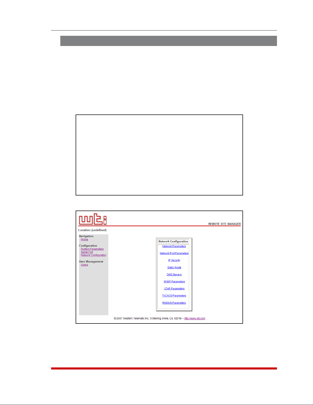
5.8. Network Configuration
The Network Parameters Menus are used to select parameters and options for the
Network Port and also allow you to implement IP Security features, which can restrict
access based on the user’s IP Address.
Although the Web Browser Interface and Text Interface allow definition of essentially
the same parameters, parameters are arranged differently in the two interfaces. In the
Text Interface, most network parameters are defined via one menu. But in the Web
Browser Interface, network parameters are divided between eight separate submenus
as described in this section.
NETWORK PARAMETERS:
COMMUNICATION SETTING SERVERS AND CLIENTS
1. IP Address: 192.168.168.168 21. Telnet Access: On
2. Subnet Mask: 255.255.255.0 22. SSH Access: On
3. Gateway Addr: (undefined) 23. Web Access: On
4. DHCP: Off 24. SYSLOG Addr: (undefined)
5. IP Security: Off 25. SNMP Access: Off
6. Static Route: Off 26. SNMP Trap: Off
7. DNS Servers: (undefined) 27. LDAP: Off
28. TACACS: Off
GENERAL PARAMETERS 29. RADIUS: Off
11. Supervisor Mode: Permit 30. PING Access: On
12. Logoff Char: ^X 31. Raw Socket Access: Off
13. Sequence Disc: One Char
14. Inact Timeout: 5 Min
15. Command Echo: On
16. Accept Break: On
Enter: #<CR> to change,
<ESC> exit ...
Configuration
Figure 5.9: Network Parameters Menu (Supervisor Mode Only)
Figure 5.10: Network Configuration Menu (Web Browser Interface)
5-24
Page 44

Configuration
To access the Network Parameters Menus, proceed as follows:
• Text Interface: Type /N and press [Enter]. The Network Parameters Menu shown
in Figure 5.9 will be displayed.
• Web Browser Interface: Click on the "Network Configuration" link on the left hand
side of the screen. The RSM will display the Network Configuration menu shown
in Figure 5.10, which allows you to access the various submenus used to configure
the network port.
Notes:
• Settings for network parameters depend on the configuration of your network.
Please contact your network administrator for appropriate settings.
• The Network Parameters Menu selects parameters for all 16 logical Network
Ports.
• When a new IP Address is selected, or the status of the DHCP feature is
changed, the unit will disconnect and reconfigure itself with the new values
when you exit the Network Parameters Menu. When configuring the unit via
Web or Telnet, make certain your DHCP server is set up to assign a known,
fixed IP address in order to simplify reconnection to the unit after the new
address has been assigned.
• The Network Parameters menu is only available when you have logged
into command mode using an account and port that permit Supervisor
commands.
The Network Parameters menu allows you to define the parameters that are discussed
in the following sections. Note that although the descriptions of network parameters are
arranged according to the Web Browser Interface, in the Text Interface, all parameters
(except IP Security configuration) are included in one menu.
5-25
Page 45

Configuration
Figure 5.11: Network Parameters Menu (Web Browser Interface)
5.8.1. Network Parameters
In the Text Interface, these parameters are accessed via the Network Configuration
menu (Figure 5.9.) In the Web Browser Interface, these parameters can be found by first
clicking the "Network Configuration" link, and then Clicking the "Network Parameters"
link to display the Network Parameters menu (Figure 5.11.)
• IP Address: (Default = 192.168.168.168.)
• Subnet Mask: (Default = 255.255.255.0.)
• Gateway Address: (Default = undefined.)
• DHCP: Enables/Disables Dynamic Host Configuration Protocol. When this option
is "On", the RSM will perform a DHCP request. Note that the MAC address for the
RSM is listed on the Network Status Screen. (Default = Off.)
Note: Before configuring this feature via Telnet or Web, make certain your
DHCP server is set up to assign a known, fixed IP address. You will need this
new IP address in order to reestablish a network connection with the RSM unit.
• Telnet Access: Enables/disables Telnet access. When Telnet Access is "Off," users
will not be allowed to establish a Telnet connection to the unit. (Default = On.)
• Web Access: Enables/disables the Web Browser Interface. When disabled, users
will not be allowed to contact the unit via the Web Browser Interface.
(Default = Off.)
• SSH Access: Enables/disables SSH communication. (Default = On.)
• SYSLOG Address: The IP Address or domain name (up to 64 characters) for the
Syslog Daemon that will receive log records generated by the RSM. For more
information, please refer to Section 9. (Default = 0.0.0.0.)
• Ping Access: Enables/Disables response to the ping command. When Disabled,
the RSM will not respond to Ping commands. (Default = On.)
• Raw Socket Access: Enables/Disables Raw Socket Protocol access to the
Network Port via Direct Connect. (Default = Off.)
5-26
Page 46

Configuration
Figure 5.12: Network Port Parameters Menu (Web Browser Interface)
5.8.2. Network Port Parameters
In the Text Interface, these parameters are found in the main Network Configuration
menu (Figure 5.9.) In the Web Browser Interface, these parameters are found by
first clicking the "Network Configuration" link, and then clicking the "Network Port
Parameters" link to display the Network Port Configuration Menu (Figure 5.12.)
• Supervisor Mode: Permits/denies access to Supervisor commands. If disabled,
the Network port is not allowed to invoke Supervisor commands. (Default =
Permit.)
Note: When Supervisor Mode for the Network Port is set to "Deny," accounts
that permit Supervisor commands will not be allowed to access command
mode via network.
• Logoff Character: Defines the Logoff Character for this port. This determines
which command(s) must be issued at this port in order to disconnect from a second
port. The Logoff Character does not apply to Telnet Direct Connections.
(Default = ^X ([Ctrl] plus [X]).)
• Sequence Disconnect: Enables/Disables and configures the Resident Disconnect
command. Offers the option to either disable the Sequence Disconnect, or select a
one character, or three character command format. (Default = One Character).
Notes:
• The One Character Disconnect is intended for situations where the
destination port should not receive the disconnect command. When the
Three Character format is selected, the disconnect sequence will pass
through to the destination port prior to breaking the connection.
• When Three Character format is selected, the Resident Disconnect uses the
format "[Enter]LLL[Enter]", where L is the selected Logoff Character.
5-27
Page 47

Configuration
• Inactivity Timeout: Enables and selects the Inactivity Timeout period for the
Network Port. If enabled, and the port does not receive or transmit data for the
specified time period, the port will disconnect. (Default = 5 Minutes).
Note: The Inactivity Timeout value is also applied to Direct Connections.
• Command Echo: Enables or Disables the command echo for the Network Port.
(Default = On).
• Accept Break: Determines whether the port will accept breaks received from the
attached device, and pass them along to a connected port. When enabled, breaks
received at this port will be passed to any port this port is connected to, and sent
to the device connected to the other port. When disabled, breaks will be refused at
this port. (Default = On.)
5-28
Page 48

IP SECURITY:
CLIENT LIST FOR “hosts.allow” FILE:
1.
2.
3.
4.
5.
6.
7.
8.
CLIENT LIST FOR “hosts.deny” FILE:
9.
10.
11.
12.
13.
14.
15.
16.
Enter: #<CR> to select menu,
<ESC> for previous menu ...
Figure 5.13: IP Security Menu (Text Interface)
Configuration
Figure 5.14: IP Security Menu (Web Browser Interface)
5.8.3. IP Security
The RSM can restrict unauthorized IP addresses from establishing an inbound Telnet
connection to the unit. This allows the user to grant Telnet access to only a specific
group of IP addresses, or block a particular IP address. In the default state, the RSM
accepts incoming IP connections from all hosts.
In the Text Interface, IP Security parameters are defined via item 5 in the Network
Configuration menu (Figure 5.9.) In the Web Browser Interface, these parameters are
found by clicking the "Network Configuration" link, and then Clicking the "IP Security"
link. In the default state, IP Security is disabled.
5-29
Page 49

Configuration
The IP Security Function employs a TCP Wrapper program which allows the use of
standard, Linux operators, wild cards and net/mask pairs to create a host based access
control list.
As shown in Figures 5.13 and 5.14, the IP Security configuration menus include
"hosts.allow" and "hosts.deny" client lists. Basically, when setting up IP Security, you
must enter IP addresses for hosts you wish to allow in the Allow list, and addresses for
hosts you wish to deny in the Deny list. Since Linux operators, wild cards and net/mask
pairs are allowed, these lists can indicate specific addresses, or a range of addresses to
be allowed or denied.
When the IP Security feature is properly enabled, and a client attempts to connect, the
RSM will perform the following checks:
1. If the client’s IP address is found in the "hosts.allow" list, the client will be granted
immediate access. Once an IP address is found in the Allow list, the RSM will not
check the Deny list, and will assume you wish to allow that address to connect.
2. If the client’s IP address is not found in the Allow list, the RSM will then proceed to
check the Deny list.
3. If the client’s IP Address is found in the Deny list, the client will not be allowed to
connect.
4. If the client’s IP Address is not found in the Deny list, the client will be allowed to
connect, even if the address was not found in the Allow list.
Notes:
• If the RSM finds an IP Address in the Allow list, it will not check the Deny list,
and will allow the client to connect.
• If both the Allow and Deny lists are left blank, then the IP Security feature will
be disabled, and all IP Addresses will be allowed to connect (providing that
the proper password and/or SSH key is supplied.)
• When the Allow and Deny lists are defined, the user is only allowed to specify
the Client List; the Daemon List and Shell Command cannot be defined.
5.8.3.1. Adding IP Addresses to the Allow and Deny Lists
To add an IP Address to the Allow or Deny list, and begin configuring the IP Security
feature, proceed as follows.
Notes:
• Both the Allow and Deny list can include Linux operators, wild cards, and
net/mask pairs.
• In some cases, it is not necessary to enter all four "digits" of the IP Address.
For example, if you wish to allow access to all IP addresses that begin with
"192," then you would only need to enter "192."
• The IP Security Configuration menu is only available when the Supervisor
Mode is active.
5-30
Page 50

Configuration
1. Access the IP Security Configuration Menu.
a) Text Interface: Type /N [Enter] to display the Network Configuration Menu.
From the Network Configuration Menu, type 5 [Enter] to display the screen
shown in Figure 5.13.
b) Web Browser Interface: Click on "Network Configuration" on the left hand
side of the screen. When the Network Configuration menu appears, click on
"IP Security" to display the screen shown in Figure 5.14.
2. Allow List: Enter the IP Address(es) for the clients that you wish to allow. Note that
if an IP Address is found in the Allow list, the client will be allowed to connect, and
the RSM will not check the Deny list.
a) Text Interface: Note the number for the first empty field in the Allow list, then
type that number at the command prompt, press [Enter], and then follow the
instructions in the resulting submenu.
b) Web Browser Interface: Place the cursor in the first empty field in the
parameters menu, then key in the desired IP Address, operators, wild cards,
and/or net/mask pairs.
3. Deny List: Enter the IP Address(es) for the clients that you wish to deny. Note that
if the client’s IP Address is not found in the Deny List, that client will be allowed to
connect. Use the same procedure for entering IP Addresses described in Step 2
above.
5-31
Page 51

Configuration
5.8.3.2. Linux Operators and Wild Cards
In addition to merely entering a specific IP address or partial IP address in the Allow or
Deny list, you may also use any standard Linux operator or wild card. In most cases,
the only operator used is "EXCEPT" and the only wild card used is "ALL," but more
experienced Linux users may note that other operators and wild cards may also be
used.
EXCEPT:
This operator creates an exception in either the "allow" list or "deny" list.
For example, if the Allow list includes a line which reads "192. EXCEPT 192.255.255.6,"
then all IP address that begin with "192." will be allowed; except 192.255.255.6
(providing that this address appears in the Deny list.)
ALL:
The ALL wild card indicates that all IP Addresses should be allowed or denied. When
ALL is included in the Allow list, all IP addresses will be allowed to connect; conversely,
if ALL is included in the Deny list, all IP Addresses will be denied (except for IP
addresses listed in the Allow list.)
For example, if the Deny list includes a line which reads "ALL EXCEPT 168.255.192.192,"
then all IP addresses except 168.255.192.192 will be denied (except for IP addresses
that are listed in the Allow list.)
Net/Mask Pairs:
An expression of the form "n.n.n.n/m.m.m.m" is interpreted as a "net/mask" pair. A host
address is matched if "net" is equal to the bitwise AND of the address and the "mask."
For example, the net/mask pattern "131.155.72.0/255.255.254.0" matches every address
in the range "131.155.72.0" through "131.155.73.255."
5-32
Page 52

Configuration
5.8.3.3. IP Security Examples
1. Mostly Closed: Access is denied by default and the only clients allowed,
are those explicitly listed in the Allow list. To deny access to all clients except
192.255.255.192 and 168.112.112.05, the Allow and Deny lists would be defined as
follows:
• Allow List:
1. 192.255.255.192
2. 168.112.112.05
• Deny List:
1. ALL
2. Mostly Open: Access is granted by default, and the only clients denied access,
are those explicitly listed in the Deny list, and as exceptions in the Allow list. To
allow access to all clients except 192.255.255.192 and 168.112.112.05, the Allow
and Deny lists would be defined as follows:
• Allow List:
1. ALL EXCEPT 192.255.255.192, 168.112.112.05
• Deny List:
1. 192.255.255.192, 168.112.112.05
Notes:
• When defining a line in the Allow or Deny list that includes several IP
addresses, each individual address is separated by either a space, a comma,
or a comma and a space as shown in Example 2 above.
• Take care when using the "ALL" wild card. When ALL is included in the Allow
list, it should always include an EXCEPT operator in order to allow the unit to
proceed to the Deny list and determine any addresses you wish to deny.
5-33
Page 53

STATIC ROUTES:
1.
2.
3.
4.
5.
6.
7.
8.
Enter: #<CR> to select menu,
<ESC> for previous menu ...
Figure 5.15: Static Route Menu (Text Interface)
Configuration
Figure 5.16: Static Route Menu (Web Browser Interface)
5.8.4. Static Route
The Static Route menu allows you to type in Linux routing commands that will be
automatically executed each time that the unit powers up or reboots. In the Text
Interface, the Static Route menu is accessed via item 6 in the Network Configuration
menu. In the Web Browser Interface, the Static Route menu is accessed by first clicking
the Network Configuration link and then clicking the Static Route link.
To access the Static Route Menus, proceed as follows:
• Text Interface: Type /N and press [Enter] to display the Network Parameters
Menu (Figure 5.9.) At the Network Parameters Menu, type 6 and press [Enter].
The Static Route Menu should appear as shown in Figure 5.15.
• Web Browser Interface: Click on the "Network Configuration" link on the left
hand side of the RSM Home screen to display the Network Configuration menu
(Figure 5.10). From the Network Configuration Menu, Click the Static Route link to
display the menu shown in Figure 5.16.
5-34
Page 54

DNS SERVER IP ADDRESSES:
1.
2.
3.
4.
Enter: #<CR> to select menu,
<ESC> for previous menu ...
Figure 5.17: Nomain Name Server Menu (Text Interface)
Configuration
Figure 5.18: Domain Name Server Menu (Web Browser Interface)
5.8.5. Domain Name Server
The Domain Name Server menu is used to select IP addresses for the Domain Name
Servers. When web and network addresses are entered, the Domain Name Server
interprets the domain name (e.g., www.wti.com), and translates it into an IP address.
Note that if you don't define at least one DNS server, then IP addresses must be used,
rather than domain names.
To access the Domain Name Server Menu, proceed as follows:
• Text Interface: Type /N and press [Enter] to display the Network Parameters
Menu (Figure 5.9.) At the Network Parameters Menu, type 7 and press [Enter].
The Static Route Menu should appear as shown in Figure 5.17.
• Web Browser Interface: Click on the "Network Configuration" link on the left
hand side of the RSM Home screen to display the Network Configuration menu
(Figure 5.10). From the Network Configuration Menu, Click the Domain Name
Server link to display the menu shown in Figure 5.18.
5-35
Page 55
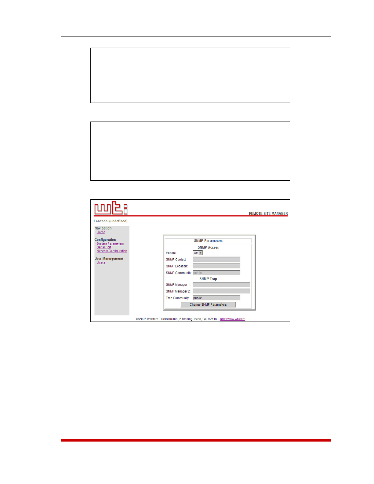
SNMP ACCESS:
1. Enable: Off
2. Contact: (undefined)
3. Location: (undefined)
4. Community: public
Enter: #<CR> to change,
<ESC> for previous menu ...
Figure 5.19: SNMP Access Menu (Text Interface)
SNMP TRAP:
Note: The SNMP trap feature is enabled by defining at least one manager.
1. Manager 1: (undefined)
2. Manager 2: (undefined)
3. Community: public
Enter: #<CR> to change,
<ESC> for previous menu ...
Figure 5.20: SNMP Trap Menu (Text Interface)
Configuration
Figure 5.21: SNMP Parameters Menu (Web Browser Interface)
5.8.6. SNMP Parameters
These menus are used to select parameters that will be used when an SNMP trap is
generated. To define or change SNMP parameters, proceed as follows:
• Text Interface: Type /N and press [Enter] to display the Network Parameters
Menu (Figure 5.9.) At the Network Parameters Menu, type 25 and press [Enter]
to display the SNMP Access Menu (Figure 5.19,) or type 26 and press [Enter] to
display the SNMP Trap Menu (Figure 5.20.)
• Web Browser Interface: Click on the "Network Configuration" link on the left
hand side of the RSM Home screen to display the Network Configuration menu
(Figure 5.10). From the Network Configuration Menu, Click the SNMP Parameters
link to display the menu shown in Figure 5.21.
5-36
Page 56

Configuration
In the Text Interface SNMP parameters are defined via two separate menus, The SNMP
Access Menu and the SNMP Trap Menu. In the Web Browser Interface, all SNMP
parameters are defined via a single menu. Both the Text Interface and Web Browser
Interface allow the following parameters to be defined:
• Enable: Enables/disables SNMP Polling. (Default = Off.)
Note: This item only applies to external SNMP polling of the RSM; it does not
effect the ability of the RSM to send SNMP traps.
• SNMP Contact: (Default = undefined.)
• SNMP Location: (Default = undefined.)
• SNMP Community: (Default = Public.)
• SNMP Manager 1: The IP Address for the first SNMP Manager. For more
information, please refer to Section 10. (Default = Undefined.)
Note: In order to enable the SNMP Trap feature, you must define at least one
SNMP Manager.
• SNMP Manager 2: (Default = Undefined.)
• Trap Community: (Default = Public.)
5-37
Page 57

LDAP:
1. Enable: Off
2. LDAP Port: 389
3. Primary Host: (undefined)
4. Secondary Host: (undefined)
5. Bind Type: Simple
6. Search Bind DN: (undefined)
7. Search Bind Password: (undefined)
8. User Search Base DN: (undefined)
9. User Search Filter: (undefined)
10. Group Membership Attribute: (undefined)
11. Group Membership Value Type: DN
12. Fallback: Off
13. LDAP Group Setup
Enter: #<CR> to change,
<ESC> for previous menu ...
Figure 5.22: LDAP Parameters Menu (Text Interface)
Configuration
Figure 5.23: LDAP Parameters Menu (Web Browser Interface)
5.8.7. LDAP Parameters
The RSM supports LADP (Lightweight Directory Access Protocol,) which allows
authentication via the "Active Directory" network Directory Service. When LDAP is
enabled and properly configured, command access rights can be granted to new users
without the need to define individual new accounts at each RSM unit, and existing users
can also be removed without the need to delete the account from each RSM unit.
This type of authentication also allows administrators to assign users to LDAP groups,
and then specify which ports the members of each group will be allowed to access at
each RSM unit.
5-38
Page 58

Configuration
In order to apply the LDAP feature, you must first define User Names and associated
Passwords and group membership via your LDAP server, and then access the RSM
command mode to enable and configure the LDAP settings and define port access
rights and command access rights for each group that you have specified at the LDAP
server.
To access the LDAP Parameters menu, access the command mode using a port and
password that permit access to Supervisor Level commands and then proceed as
follows:
• Text Interface: Type /N and press [Enter] to display the Network Parameters
Menu (Figure 5.9.) At the Network Parameters Menu, type 27 and press [Enter] to
display the LDAP parameters menu (Figure 5.22.)
• Web Browser Interface: At the Home Screen, click on the Network Configuration
link to display the Network Configure menu (Figure 5.10,) and then click on the
LDAP Parameters link to display the LDAP Parameters menu (Figure 5.23.)
Notes:
• Port access rights are not defined at the LDAP server. They are defined via
the LDAP Group configuration menu on each RSM unit and are specific to
that RSM unit alone.
• When LDAP is enabled and properly configured, LDAP authentication will
supersede any passwords and access rights that have been defined via the
RSM user directory.
• If no LDAP groups are defined on a given RSM unit, then access rights will
be determined as specified by the "default" LDAP group.
• The "default" LDAP group cannot be deleted.
The LDAP Parameters Menu (Figure 5.22 or Figure 5.23) allows you to define the
following parameters:
• Enable: Enables/disables LDAP authentication. (Default = Off.)
• LDAP Port: Defines the port that will be used to communicate with the LDAP
server. (Default = 389.)
• Primary Host: Defines the IP address or domain name (up to 64 characters) for
the primary LDAP server. (Default = undefined.)
• Secondary Host: Defines the IP address or domain name (up to 64 characters) for
the secondary (fallback) LDAP server. (Default = undefined.)
• Bind Type: Sets the LDAP bind request password type. Note that in the Text
Interface, when the Bind Type is set to "Kerberos" LDAP menu will include an
additional prompt (item 14) that is used to select Kerberos parameters as described
in Section 5.8.7.5. In the Web Interface, the link to the kerberos parameters menu
is located at the bottom of the LDAP Parameters Menu. (Default = Simple.)
• Search Bind DN: Selects the user name who is allowed to search the LDAP
directory. (Default = undefined.)
• Search Bind Password: Sets the Password for the user who is allowed to search
the LDAP directory. (Default = undefined.)
5-39
Page 59

Configuration
• User Search Base DN: Sets the directory location for user searches.
(Default = undefined.)
• User Search Filter: Selects the attribute that lists the user name. Note that this
attribute should always end with "=%S" (no quotes.) (Default = undefined.)
• Group Membership Attribute: Selects the attribute that list group membership(s).
(Default = undefined.)
• Group Membership Value Type: (Default = DN.)
• Fallback: Enables/Disables the LDAP fallback feature. When enabled, the RSM
will revert to it's own internal user directory (see Section 5.5) if no defined users are
found via the LDAP server. In this case, port access rights will then be granted as
specified in the default LDAP group. (Default = Off.)
5.8.7.1. Adding LDAP Groups
Once you have defined several users and passwords via your LDAP server, and
assigned those users to LDAP Groups, you must then grant command and port access
rights to each LDAP Group at each individual RSM unit.
To add LDAP groups to your RSM unit, access the command mode using a port and
password that permit access to Supervisor Level commands, and then proceed as
follows:
• Text Interface: Type /N and press [Enter] to display the Network Parameters
Menu (Figure 5.9.) At the Network Parameters Menu, type 27 and press [Enter] to
display the LDAP parameters menu (Figure 5.22), then type 13 and press [Enter] to
display the LDAP Group Menu (Figure 5.24.) At the LDAP Group Menu, type 2 and
press [Enter] to display the Add LDAP Group menu (Figure 5.25.)
• Web Browser Interface: At the RSM Home Screen, click on the Network
Configuration link to display the Network Configure menu (Figure 5.10,)
and then click on the LDAP Parameters link to display the LDAP Parameters
menu (Figure 5.23.) At the LDAP Parameters menu, click on the LDAP Group
Configuration link to display the LDAP Group Configuration menu, then click the
Add LDAP Group link to display the Add LDAP Group menu (Figure 5.26.)
LDAP GROUP:
1. View LDAP Groups
2. Add LDAP Group
3. Modify LDAP Group
4. Delete LDAP Group
Enter: #<CR> to select,
<ESC> for previous menu ...
Figure 5.24: LDAP Group Configuration (Text Interface)
5-40
Page 60

ADD LDAP GROUP:
1. LDAP Group
2. Access Level: User
3. Port Access:
PORT# PORT NAME ACCESS PORT# PORT NAME ACCESS
------------------------------- ------------------------------ 1 (undefined) Off 6 (undefined) Off
2 (undefined) Off 7 (undefined) Off
3 (undefined) Off 8 (undefined) Off
4 (undefined) Off 9 MODEM Off
5 (undefined) Off
Enter: #<CR> to select,
<ESC> to return to previous menu ...
Figure 5.25: Add LDAP Group Menu (Text Interface; RSM-8 Shown)
Configuration
Figure 5.26: Add LDAP Group Menu (Web Browser Interface; RSM-8 Shown)
The Add LDAP Group menus allow the following parameters to be defined:
• LDAP Group: Note that this name must match the LDAP Group names that you
have assigned to users at your LDAP server. (Default = undefined.)
• Access Level: Sets the command mode and port access level. When this
feature is "On", members of this group will be allowed to access Supervisor Level
commands and access all ports; when the feature is "Off", group members will not
be allowed to access Supervisor Level commands and will be restricted to the ports
that are specifically allowed for this group. (Default = Off.)
• Port Access: This prompt is used to determine which ports the user will be
allowed to create connections with. (Default = All Ports Off.)
Notes:
• On RSM-8 units, the internal modem port is Port 9.
• On RSM-16 units, the internal modem port is Port 17.
• On RSM-32 units, the internal modem port is Port 33.
5-41
Page 61

VIEW LDAP GROUP DETAILS:
1. LDAP Group default
2. Access Level: Admin
3. Port Access:
PORT# PORT NAME ACCESS PORT# PORT NAME ACCESS
------------------------------- ------------------------------ 1 (undefined) On 6 (undefined) On
2 (undefined) On 7 (undefined) On
3 (undefined) On 8 (undefined) On
4 (undefined) On 9 MODEM On
5 (undefined) On
Enter: <CR> or <ESC> to return to previous menu...
Figure 5.27: View LDAP Group Menu (Text Interface; RSM-8 Shown)
Configuration
Figure 5.28: View LDAP Group Menu (Web Browser Interface; RSM-8 Shown)
5.8.7.2 Viewing LDAP Groups
If you want to examine an existing LDAP group definition on an RSM unit, the "View
LDAP Groups" function can be used to review the group's Access Level and Port Access
Settings. To view an existing LDAP group, proceed as follows:
• Text Interface: Type /N and press [Enter] to display the Network Parameters
Menu (Figure 5.9.) At the Network Parameters Menu, type 27 and press [Enter] to
display the LDAP parameters menu (Figure 5.22), then type 13 and press [Enter]
to display the LDAP Group Menu (Figure 5.24), then type 1 and press [Enter]. The
RSM will prompt you to select the desired group; key in the name of the group and
press [Enter], the RSM will display the View LDAP Group screen (Figure 5.27.)
• Web Browser Interface: At the RSM Home Screen, click on the "Network
Configuration" link to display the Network Configure menu (Figure 5.10,) and
then click on the "LDAP Parameters" link to display the LDAP Parameters
menu (Figure 5.23.) At the LDAP Parameters menu, click on the "LDAP Group
Configuration" link to display the LDAP Group Configuration menu, then click the
"View/Modify LDAP Group" link to display the Choose LDAP Group menu; use the
drop down menu to select the desired group, select "View LDAP Group" and then
click the "Choose LDAP Group" button to display the screen shown in Figure 5.28.
5-42
Page 62
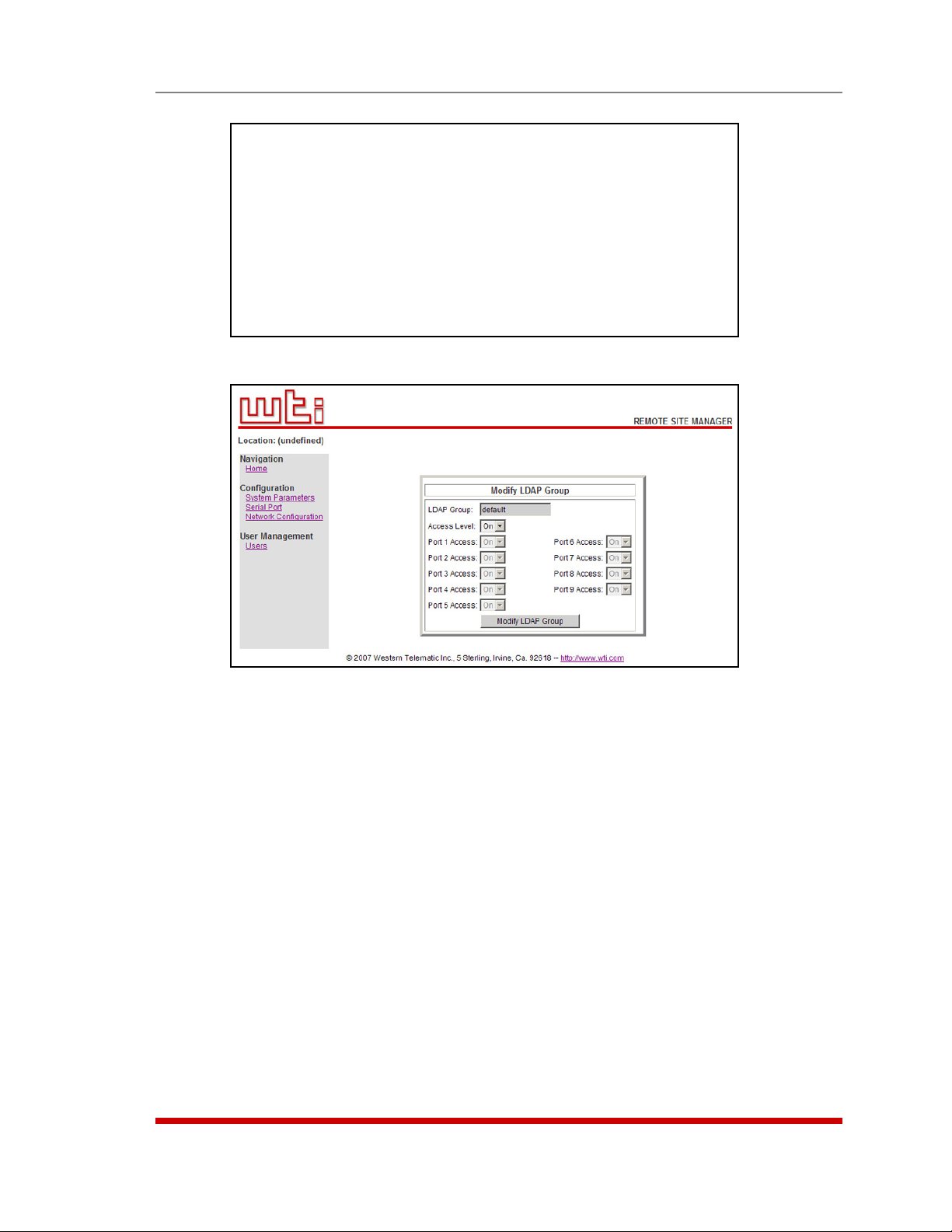
MODIFY LDAP GROUP DETAILS:
1. LDAP Group default
2. Access Level: Admin
3. Port Access:
PORT# PORT NAME ACCESS PORT# PORT NAME ACCESS
------------------------------- ------------------------------ 1 (undefined) On 6 (undefined) On
2 (undefined) On 7 (undefined) On
3 (undefined) On 8 (undefined) On
4 (undefined) On 9 MODEM On
5 (undefined) On
Enter: #<CR> to select,
<ESC> to return to previous menu ...
Figure 5.29: Modify LDAP Group Menu (Text Interface; RSM-8 Shown)
Configuration
Figure 5.30: Modify LDAP Group Menu (Web Browser Interface; RSM-8 Shown)
5.8.7.3. Modifying LDAP Groups
If you want to modify an existing LDAP Group in order to change command access
rights or port access rights, the "Modify LDAP Group" function can be used to edit group
parameters. To Modify an existing LDAP Group, proceed as follows:
• Text Interface: Type /N and press [Enter] to display the Network Parameters
Menu (Figure 5.9.) At the Network Parameters Menu, type 27 and press [Enter] to
display the LDAP parameters menu (Figure 5.22), then type 13 and press [Enter]
to display the LDAP Group Menu (Figure 5.24), then type 3 and press [Enter]. The
RSM will prompt you to select the desired group; key in the name of the group and
press [Enter], the RSM will display the Modify LDAP Group screen (Figure 5.29.)
• Web Browser Interface: At the RSM Home Screen, click on the "Network
Configuration" link to display the Network Configure menu (Figure 5.10,) and
then click on the "LDAP Parameters" link to display the LDAP Parameters
menu (Figure 5.23.) At the LDAP Parameters menu, click on the "LDAP Group
Configuration" link to display the LDAP Group Configuration menu, then click the
"View/Modify LDAP Group" link to display the Choose LDAP Group menu; use the
drop down menu to select the desired group, select "Modify LDAP Group" and then
click the "Choose LDAP Group" button to display the screen shown in Figure 5.30.
5-43
Page 63
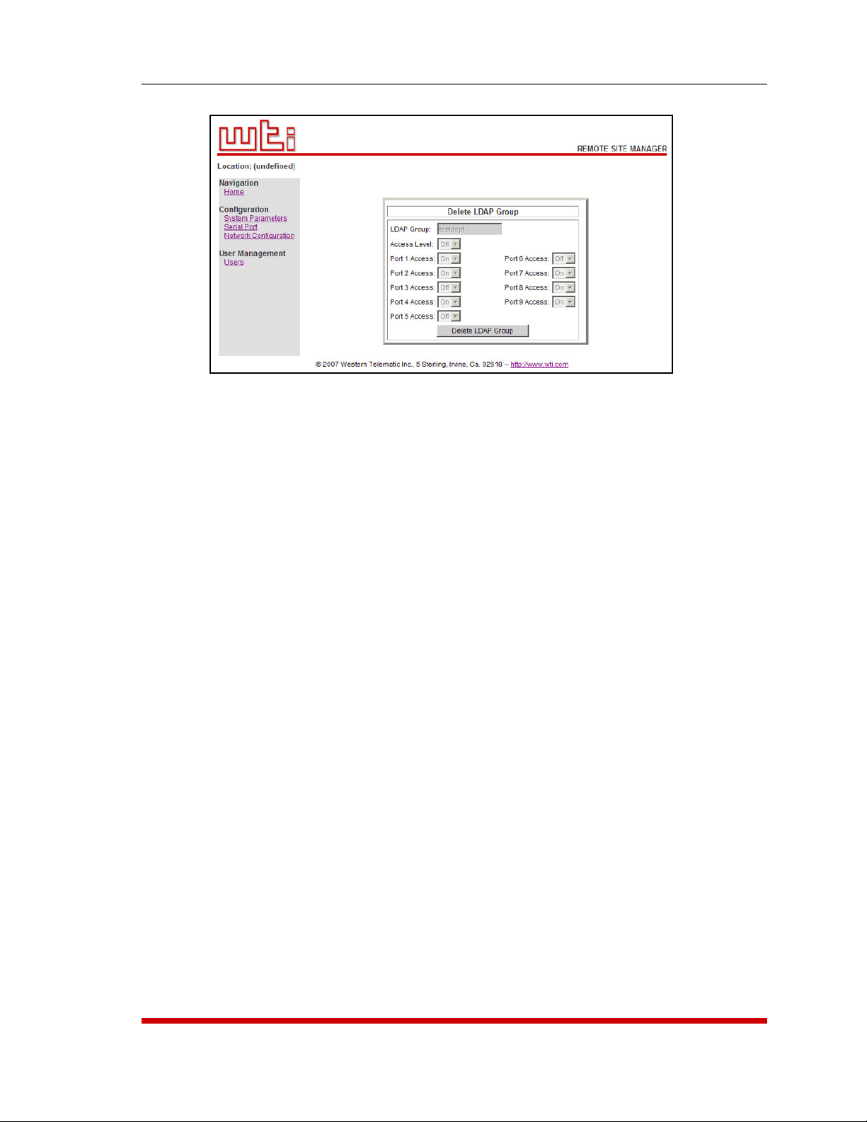
Configuration
Figure 5.31: Delete LDAP Group Menu (Web Browser Interface)
5.8.7.4. Deleting LDAP Groups
The Delete LDAP Group function is used to delete LDAP Groups that are no longer in
use. To delete an existing LDAP Group, proceed as follows:
• Text Interface: Type /N and press [Enter] to display the Network Parameters
Menu (Figure 5.9.) At the Network Parameters Menu, type 27 and press [Enter] to
display the LDAP parameters menu (Figure 5.22), then type 13 and press [Enter]
to display the LDAP Group Menu (Figure 5.24), then type 4 and press [Enter]. The
RSM will prompt you to select the desired group; key in the name of the group and
press [Enter], the RSM will delete the specified LDAP Group immediately.
• Web Browser Interface: At the RSM Home Screen, click on the "Network
Configuration" link to display the Network Configure menu (Figure 5.10,) and
then click on the "LDAP Parameters" link to display the LDAP Parameters
menu (Figure 5.23.) At the LDAP Parameters menu, click on the "LDAP Group
Configuration" link to display the LDAP Group Configuration menu, then click the
"View/Modify LDAP Group" link to display the Choose LDAP Group menu; use the
drop down menu to select the desired group, select "Delete LDAP Group" and then
click the "Choose LDAP Group" button to display the screen shown in Figure 5.31.
If the Delete LDAP Group menu shows the desired group, then click the "Delete
LDAP Group" button to immediately delete the group.
5-44
Page 64
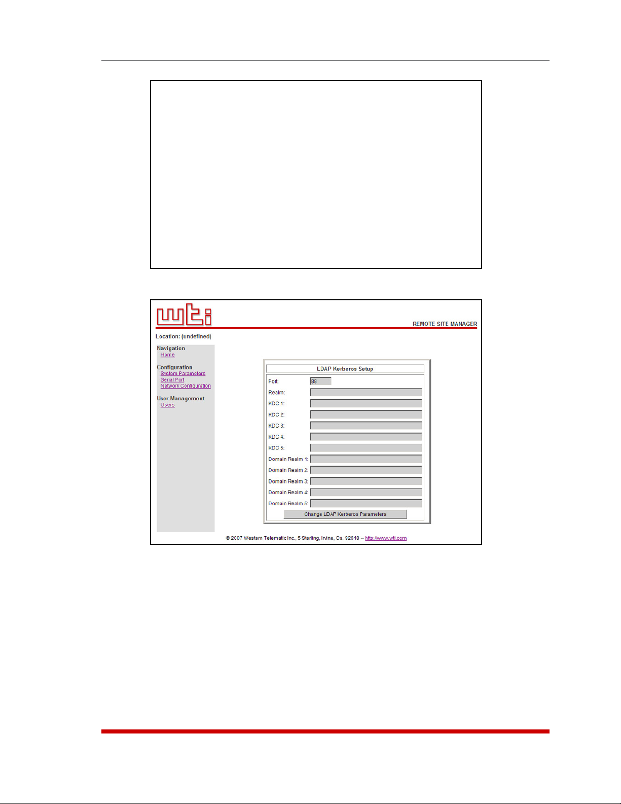
LDAP KERBEROS SETUP
1. Port : 88
2. Realm :
KDC (KDC1 - KDC5)
3.
4.
5.
6.
7.
Domain Realm (Domain Realm1 - Domain Realm5)
8.
9.
10.
11.
12.
Enter: #<CR> to select,
<ESC> for previous menu ...
Figure 5.32: LDAP Kerberos Set Up Menu (Text Interface)
Configuration
Figure 5.33: LDAP Kerberos Set Up Menu (Web Browser Interface)
5.8.7.5. LDAP Kerberos Set Up
Kerberos is a network authentication protocol, which provides a secure means of
identity verification for users who are communicating via an insecure network.
5-45
Page 65

Configuration
To access the LDAP Kerberos Set Up menu, access the command mode using a port
and password that permit access to Supervisor Level commands and then proceed as
follows:
• Text Interface: Type /N and press [Enter] to display the Network Parameters
Menu (Figure 5.9.) At the Network Parameters Menu, type 27 and press [Enter]
to display the LDAP Parameters menu (Figure 5.22.) At the LDAP Parameters
Menu, type 5 and press [Enter] and then use the resulting submenu to set the
Bind Type to Kerberos. Next, return to the LDAP Parameters menu. Note that the
LDAP Parameters Menu now includes a prompt which is used to select Kerberos
parameters. Type 14 and press [Enter] to display the Kerberos Set Up menu as
shown in Figure 5.32.
• Web Browser Interface: At the Home Screen, click on the Network Configuration
link to display the Network Configure menu (Figure 5.10,) and then click on the
LDAP Parameters link to display the LDAP Parameters menu (Figure 5.23.) At the
LDAP Parameters menu, click on the LDAP Kerberos Setup link to display the LDAP
Kerberos Setup menu as shown in Figure 5.33.
The LDAP Kerberos Setup menu allows you to define the following parameters:
• Port: (Default = 88.)
• Realm: (Default = Undefined.)
• Key Distribution Centers (KDC1 through KDC5): (Default = Undefined.)
• Domain Realms 1 through 5: (Default = Undefined.)
5-46
Page 66

TACACS:
1. Enable: Off
2. Primary address: (undefined)
3. Secondary address: (undefined)
4. Secret Word: (undefined)
5. Fallback Timer: 3 Sec
6. Fallback Local: Off
7. Authentication Port: 49
Enter: #<CR> to change,
<ESC> for previous menu ...
Figure 5.34: The TACACS Parameters Menu (Text Interface)
Configuration
Figure 5.35: The TACACS Parameters Menu (Web Browser Interface)
5.8.8. TACACS Parameters
To access the TACACS Configuration Menus, proceed as follows:
• Text Interface: Type /N and press [Enter] to access the Network Configuration
Menu. From the Network Configuration Menu, type 28 and press [Enter] to display
the TACACS Configuration Menu (Figure 5.34.)
• Web Browser Interface: Click on the "Network Configuration" link to display the
menu shown in Figure 5.10, then click the "TACACS Parameters" link to display the
TACACS Configuration Menu (Figure 5.35.)
The TACACS Configuration Menus offer the following options:
• Enable: Enables/disables the TACACS feature at the Network Port. (Default = Off.)
• Primary Address: Defines the IP address or domain name (up to 64 characters)
for your primary TACACS server. (Default = undefined.)
• Secondary Address: Defines the IP address or domain name (up to 64 characters)
for your secondary, fallback TACACS server (if present.) (Default = undefined.)
5-47
Page 67

Configuration
• Secret Word: Defines the shared TACACS Secret Word for both TACACS servers.
(Default = undefined.)
• Fallback Timer: Determines how long the RSM will continue to attempt to contact
the primary TACACS Server before falling back to the secondary TACACS Server.
(Default = 3 Seconds.)
• Fallback Local: Determines whether or not the RSM will fallback to its own
password/username directory when an authentication attempt fails. When enabled,
the RSM will first attempt to authenticate the password by checking the TACACS
Server; if this fails, the RSM will then attempt to authenticate the password by
checking its own internal username directory. (Default = Off.)
• Authentication Port: The port number for the TACACS function. (Default = 49.)
5-48
Page 68

RADIUS:
1. Enable: Off
2. Primary Address: (undefined)
3. Primary Secret Word: (undefined)
4. Secondary Address: (undefined)
5. Secondary Secret Word: (undefined)
6. Fallback Timer: 3 Sec
7. Fallback Local: Off
8. Authentication Port: 1812
9. Accounting Port: 1813
Enter: #<CR> to change,
<ESC> for previous menu ...
Figure 5.36: The RADIUS Parameters Menu (Text Interface)
Configuration
Figure 5.37: The RADIUS Parameters Menu (Web Browser Interface)
5.8.9. RADIUS Parameters
To access the RADIUS Configuration Menus, proceed as follows:
• Text Interface: Type /N and press [Enter] to access the Network Configuration
Menu. From the Network Configuration Menu, type 29 and press [Enter] to display
the RADIUS Configuration Menu (Figure 5.36.)
• Web Browser Interface: Click on the "Network Configuration" link to display the
menu shown in Figure 5.10, then click the "RADIUS Parameters" link to display the
RADIUS Configuration Menu (Figure 5.37.)
The RADIUS Configuration Menus offer the following options:
• Enable: Enables/disables the RADIUS feature at the Network Port. (Default = Off.)
• Primary Address Defines the IP address or domain name (up to 64 characters
long) for your primary RADIUS server. (Default = undefined.)
• Primary Secret Word: Defines the RADIUS Secret Word for the primary RADIUS
server. (Default = undefined.)
5-49
Page 69

Configuration
• Secondary Address: Defines the IP address or domain name (up to 64 characters
long) for your secondary, fallback RADIUS server (if present.)
(Default = undefined.)
• Secondary Secret Word: Defines the RADIUS Secret Word for the secondary
RADIUS server. (Default = undefined.)
• Fallback Timer: Determines how long the RSM will continue to attempt to contact
the primary RADIUS Server before falling back to the secondary RADIUS Server.
(Default = 3 Seconds.)
• Fallback Local: Determines whether or not the RSM will fallback to its own
password/username directory when an authentication attempt fails. When enabled,
the RSM will first attempt to authenticate the password by checking the RADIUS
Server; if this fails, the RSM will then attempt to authenticate the password by
checking its own internal username directory. This parameter offers three options:
◆
Off: Fallback Local is disabled (Default.)
◆
On (All Failures): Fallback Local is enabled, and the unit will fallback to it's
own internal user directory when it cannot contact the Radius Server, or when a
password or username does not match the Radius Server.
◆
On (Transport Failure): Fallback Local is enabled, but the unit will only fallback
to it's own internal user directory when it cannot contact the Radius Server.
• Authentication Port: The Authentication Port number for the RADIUS function.
(Default = 1812.)
• Accounting Port: The Accounting Port number for the RADIUS function.
(Default = 1813.)
5-50
Page 70

Configuration
COPY PORT PARAMETERS:
COMMUNICATION SETTING PORT MODE PARAMETERS
1. Baud Rate: 21. Port Name:
2. Bits/Parity: 22. Port Mode:
3. Stop Bits: 23. DTR Output:
4. Handshake: 24. Buffer Params: ---
25. Modem Params: ---
GENERAL PARAMETERS NETWORK SERVICES
11. Supervisor Mode: 31. Direct Connect:
12. Logoff Char:
13. Sequence Disc:
14. Inact Timeout:
15. Command Echo: 32. Syslog: ---
16. Accept Break: 33. SNMP Trap Lv: ---
Enter: #<CR> to define parameter.
Port 1 and internal modem port restricted values NOT changed,
-<CR> to remove all values set, X<CR> to exit WITHOUT copy,
<ESC> to copy to ports and exit ...
Figure 5.38: The Copy Port Parameters Menu
5.9. Copying Parameters to Several RS-232 Ports (Text Interface Only)
When the /CP command (Copy Port Parameters) is invoked, the unit will display a menu
which allows you to select parameters, and copy them to all or several RS-232 ports.
The Copy Port Parameters menu can set all parameters for the specified port(s), or
define only a select group of parameters for a specific group of ports.
Notes:
• The /CP command is not available via the Web Browser Interface.
• The /CP command will not copy parameters to the Network Port or Internal
Modem Port.
• The /CP command is only available to accounts and ports that permit
Supervisor commands.
• The /CP command cannot be used to set Ports 1 or 2 to Passive or Buffer
Mode, or to disable the Supervisor Mode at Ports 1 or 2.
To copy parameters to all or several RS-232 ports, proceed as follows:
1. Use the Text Interface to enter command mode via an account and port that permit
access to Supervisor commands.
5-51
Page 71

Configuration
2. Invoke the /CP command at the command prompt; the menu shown in Figure 5.38
will be displayed. The following options are available:
a) Copy to All Ports: Type /CP [Enter].
b) Copy to a Range of Ports: Type /CP m-n [Enter]. Where m and n are port
numbers that specify the desired range. For example, to copy parameters to
ports 3 through 7, type /CP 3-7 and press [Enter].
c) Copy to Several Ports: Type /CP m,n,x [Enter]. Where m, n and x are the
numbers of the desired ports. For example, to copy parameters to ports 3, 5,
and 7, type /CP 3,5,7 [Enter].
d) Combination: To invoke the /CP command in a manner where a range
of ports is specified, along with several ports outside the range, type /CP
m,n,x-z [Enter]. Where m, n, x, and z are port numbers. For example to
copy parameters to ports 3 and 5 plus ports 7 through 9, type
/CP 3,5,7-9 [Enter].
3. Selecting Parameters: To select parameters to be copied, key in the number for
the desired parameter, press [Enter], then follow the instructions in the submenu.
Note: The /CP command will only copy the parameters currently displayed by
the Copy Port Parameters menu.
4. Clear Menu: After defining several parameters, if you wish to clear the /CP menu
and start again, type - (dash) and press [Enter], the menu will be reset.
5. Exit Without Copy: To exit from the Copy Parameters menu without copying
selected parameters, type X [Enter]. The RSM will return to the command prompt.
6. Copy Parameters: When you have finished selecting parameters, press [Esc] to
copy the selected parameters.
5.10. Save User Selected Parameters
Although this step is optional, it is strongly recommended to save all user-defined
parameters to an ASCII file as described in Section 11. This will allow quick recovery in
the event of accidental deletion or reconfiguration of port parameters.
5-52
Page 72

6. The Status Screens
The Status Screens display connection status and communication parameters for the
RS232 ports and the Network Port. There are four different status screens; The Port
Status Screen (/S), the Port Diagnostics Screen (/SD), the Network Status Screen (/SN),
and the Port Parameters Screens (/W).
Note: The status screens discussed in this section are only available via the
Text Interface. The status screens cannot be accessed via the Web Browser
Interface.
6-1
Page 73

The Status Screens
PORT STATUS:
Site ID: (undefined) 02/07/2007 00:33:38 GMT (GMT+0000)
PORT | NAME | USERNAME | STATUS | MODE | BUFFER COUNT
-----+------------------+------------------+--------+--------+------------- 01 | (undefined) | | Free | Any | 0
02 | (undefined) | | Free | Any | 0
03 | (undefined) | | Free | Pass | 0
04 | (undefined) | | Free | Pass | 0
05 | (undefined) | | Free | Pass | 0
06 | (undefined) | | Free | Pass | 0
07 | (undefined) | | Free | Pass | 0
08 | (undefined) | | Free | Pass | 0
09 | MODEM | | Free | Modem | 0
Enter /H for command menu.
RSM>
Figure 6.1: Port Status Screen (Sample Data Shown - RSM-8 Unit Shown)
6.1. The Port Status Screen (/S)
The Port Status Screen lists the general status of the RSM’s sixteen RS-232 ports. To
display the Port Status Screen, access the Text Interface command mode and type /S
[Enter], the screen will appear as shown in Figure 6.1.
Note that the screen format will vary, depending upon whether the user account permits
or denies access to Supervisor commands. If the username entered at login does not
allow Supervisor commands, then the Port Status Screen will only display the status of
the ports allowed by that account.
The Port Status Screen lists the following items:
• Port: The Port Number.
Notes:
• On RSM-8 units, the internal modem port is Port 9.
• On RSM-16 units, the internal modem port is Port 17.
• On RSM-32 units, the internal modem port is Port 33.
• Name: The user-defined name for each port.
• Username: The username that was entered in order to access command mode via
this port.
• Status: The connect status of each port.
◆
If the port is connected to an RS232 port, this column will list the number of
the other RSM port in "c-nn" format, where "nn" is the number of the RSM port
connected to this port (for example, "C-07".)
◆
If the connected port is listed as "Nn" (where "n" is a number), this indicates that
the RSM RS232 port is connected to the Network port. The numbers indicate
which of the available Telnet sessions is being used (for example, "C-N5".)
• Mode: The user-selected Port Mode.
• Buffer Count: The amount of data (in bytes) stored in the buffer for this port.
6-2
Page 74
The Status Screens
PORT DIAGNOSTICS:
Site ID: (undefined) 02/07/2007 00:34:51 GMT (GMT+0000)
PORT | NAME | STATUS | BAUD | COM | HS | MODE | BUF | CTS
-----+------------------+--------+--------+-----+------+--------+-------+--- 01 | (undefined) | Free | 9600 | 8N1 | RTS | Any | 0 | H
02 | (undefined) | Free | 9600 | 8N1 | RTS | Any | 0 | L
03 | (undefined) | Free | 9600 | 8N1 | RTS | Pass | 0 | L
04 | (undefined) | Free | 9600 | 8N1 | RTS | Pass | 0 | L
05 | (undefined) | Free | 9600 | 8N1 | RTS | Pass | 0 | L
06 | (undefined) | Free | 9600 | 8N1 | RTS | Pass | 0 | L
07 | (undefined) | Free | 9600 | 8N1 | RTS | Pass | 0 | L
08 | (undefined) | Free | 9600 | 8N1 | RTS | Pass | 0 | L
09 | MODEM | Free | 57.6K | 8N1 | RTS | Modem | 0 | H
Enter /H for command menu.
RSM>
Figure 6.2: Port Diagnostics Screen (RSM-8 Shown)
6.2. The Port Diagnostics Screen (/SD)
The Port Diagnostics Screen provides more detailed information about each port. To
display the Port Diagnostics Screen, access the Text Interface command mode and type
/SD [Enter], the screen will appear as shown in Figure 6.2.
Note that the screen format will vary, depending upon whether your account permits
or denies access to Supervisor commands. If the username entered at login does not
allow Supervisor commands, then the Port Diagnostics Screen will only display the
status of the ports allowed by that account. Ports that are not assigned to the account
will not be displayed.
The Port Diagnostics Screen lists the following items:
• Port: The Port Number. If this column contains a plus sign (+) next to the port
number, this indicates that the port is allowed to invoke Supervisor commands,
providing the user account allows access to these commands.
• Name: The user-defined name for each port.
• Status: The connect status for each port.
◆
When the port is connected, this column will list the number of the other port
connected to this port. If the column contains an asterisk, this indicates the port
has accessed command mode.
◆
If the connected port is listed as "Nn" (where "n" is a number), this indicates that
the RS232 port is connected to the Network port. The numbers indicate which of
the available Telnet sessions is being used (for example, "C-06".)
• Baud: The baud rate selected for each port.
• COM: The Data Bits, Parity, and Stop Bits selected for each port. For example,
"8N1" indicates Eight data bits, No parity, and One stop bit.
• HS: The handshaking (flow control) mode for each port.
• Mode: The user-selected Port Mode.
• BUF: The amount of data (in bytes) currently stored in the buffer for this port.
• CTS: The High/Low status of the CTS line at the RS232 interface.
6-3
Page 75

The Status Screens
NETWORK STATUS: MAC Address: 00-09-9b-00-b7-fa
PORT|TCP PORT|STATUS| USERNAME |PORT|TCP PORT|STATUS| USERNAME |
---------------------------------------------------------------------------N1 | 23|Active|super |N17 | | Free | |
N2 | 23|Active|super |N18 | | Free | |
N3 | | Free | |N19 | | Free | |
N4 | | Free | |N20 | | Free | |
N5 | | Free | |N21 | | Free | |
N6 | | Free | |N22 | | Free | |
N7 | | Free | |N23 | | Free | |
N8 | | Free | |N24 | | Free | |
N9 | | Free | |N25 | | Free | |
N10 | | Free | |N26 | | Free | |
N11 | | Free | |N27 | | Free | |
N12 | | Free | |N28 | | Free | |
N13 | | Free | |N29 | | Free | |
N14 | | Free | |N30 | | Free | |
N15 | | Free | |N31 | | Free | |
N16 | | Free | |N32 | | Free | |
----------------------------------------------------------------------------
Enter <CR> to show more, <ESC> to quit...
Figure 6.3: Network Status Screen
6.3. The Network Status Screen (/SN)
This screen lists current conditions for the Network Port. To display the Network Status
Screen, type /SN and press [Enter]. The Network Status Screen is only available when
you have logged in using an account and port that permit Supervisor commands.
Note that the RSM will allow up to sixty four simultaneous inbound TCP connections,
and that the Network Status Screen will report the current status of all sixty four TCP
ports. The first screen shown will list ports N1 through N32; to display additional ports,
press [Enter].
As shown in Figure 6.3, the Network Status Screen lists the following:
• MAC Address: The permanent physical address assigned to the Network Card.
• Port: The Network Port Number for each logical TCP Port. For more information,
please refer to Section 8.1.
• TCP Port: The logical TCP port number to which each Telnet session is connected.
Normally, when a Telnet session has been established, this field will list port number
23, however, if the Direct Connect feature has been used to establish a connection,
the TCP Port number will be listed as described in Section 8.3.3.
• Status: The status for each TCP port.
◆
If the Status Column reads "Active," this indicates the port has accessed
command mode.
◆
If this Telnet session is connected to an RS232 Port, this column will read "C-nn,"
where "nn" indicates the connected port for each Telnet session.
• Username: The username that was entered at this port in order to access
command mode.
6-4
Page 76

PORT PARAMETERS #03:
COMMUNICATION SETTING PORT MODE PARAMETERS
1. Baud Rate: 9600 21. Port Name:
2. Bits/Parity: 8-None 22. Port Mode: Passive
3. Stop Bits: 1 23. DTR Output: Pulse
4. Handshake: RTS/CTS 24. Buffer Params: ---
25. Modem Params: ---
GENERAL PARAMETERS NETWORK SERVICES
11. Supervisor Mode: Permit 31. Direct Connect: Off
12. Logoff Char: ^X Telnet Port: ---
13. Sequence Disc: One Char SSH Port: ---
14. Inact Timeout: 5 Min Raw Port: ---
15. Command Echo: On 32. Syslog: ---
16. Accept Break: On 33. SNMP Trap Lv: ---
RSM>
Figure 6.4: Port Parameters Screen (RS232 Port Shown)
NETWORK PARAMETERS:
COMMUNICATION SETTING SERVERS AND CLIENTS
1. IP Address: 192.168.100.48 21. Telnet Access: On
2. Subnet Mask: 255.255.255.0 22. SSH Access: On
3. Gateway Addr: (undefined) 23. Web Access: On
4. DHCP: Off 24. SYSLOG Addr: (undefined)
5. IP Security: Off 25. SNMP Access: Off
6. Static Route: Off 26. SNMP Trap: Off
7. DNS Servers: (undefined) 27. LDAP: Off
28. TACACS: Off
GENERAL PARAMETERS 29. RADIUS: Off
11. Supervisor Mode: Permit 30. PING Access: On
12. Logoff Char: ^X 31. Raw Socket Access: Off
13. Sequence Disc: One Char
14. Inact Timeout: 5 Min
15. Command Echo: On
16. Accept Break: On
RSM>
Figure 6.5: Port Parameters Screen (Network Port Shown)
The Status Screens
6.4. The Port Parameters Screens (/W)
The /W (Who) command displays more detailed information about an individual
RSM port. Rather than listing general connection information for all ports, the Port
Parameters screen lists all defined parameters for a specific port.
The Port Parameters Screens are available to accounts that permit Supervisor
commands and accounts that do not permit Supervisor commands. Note however, that
if your account that does not permit Supervisor commands, the RSM will only display
information for the port from which you have logged in.
The /W command can be applied to either an RS232 Port or the Network Port. Figure
6.4 shows the screen displayed when the /W command is applied to an RS232 Port,
and Figure 6.5 shows the screen displayed when an account that permits Supervisor
commands applies the /W command to the Network Port.
6-5
Page 77

The Status Screens
The /W command uses the following format:
/W xx [Enter]
Where xx is the desired port number. If the /W command is invoked at a serial port, by
a user with access to Supervisor Level commands, then the letter "N" can be entered as
the command argument to display parameters for the Network Port.
Note: When command mode is accessed via the Network Port using an
account that does not permit Supervisor commands, the /W command will
only display the Sequence Disconnect, Logoff Character, and the status of the
Accept Break item.
6-6
Page 78

7. Operation
This section discusses the procedures for connecting and disconnecting ports, and
describes the various port modes.
Note: The Web Browser Interface cannot be used to connect or disconnect
ports. In order to connect or disconnect ports, you must access command
mode via the Text Interface.
7.1. Any-to-Any Mode
Any-to-Any Mode Ports can be connected to other Any-to-Any, Passive, Buffer, or
Modem Mode ports by accessing command mode via the Text Interface and issuing
the /C Command. All ports can be configured for +Any-to-Any Mode, and it is also the
default mode for Ports 1 and 2.
7.1.1. Port Connection and Disconnection
The RSM allows communication between devices without the requirement that both
ports use the same communication parameters.
7.1.1.1. Connecting Ports
Two different types of connections can be made between RSM ports; Resident
Connections and Third Party Connections.
• Resident Connections: Your resident port issues a /C command to connect to a
second port. For example, Port 4 issues the /C command to connect to Port 5.
• Third Party Connections: (Supervisor Only) Your resident port issues a /C
command to create a connection between two other ports. For example, Port 1 is
your resident port, and Port 1 issues a command to connect Port 2 to Port 3.
Notes:
• Third Party Connections can only be initiated by accounts and ports that
permit Supervisor commands.
• The RS232 Ports cannot employ the /C command to initiate a connection to
the Network Port.
• If your account does not permit Supervisor commands, you will only be able
to connect to ports allowed by your account. Accounts with Supervisor
access are allowed to connect to all RS232 ports.
7-1
Page 79

To Connect ports, proceed as follows:
1. Access command mode via the Text Interface.
2. Invoke the /C command to connect the desired ports.
a) Resident Connect: To connect your resident port to another port, type /C xx
[Enter]. Where xx is the number or name of the port you want to connect.
The RSM will display the numbers of the connected ports, along with the
command required in order to disconnect the two ports.
Example: To connect your resident port to Port 8, type /C 8 [Enter].
b) Third Party Connect: (Supervisors Only) To connect any two ports (other than
your resident port), type /C xx XX [Enter]. Where xx and XX are two port
names or numbers. The RSM will display the numbers of the two connected
ports.
Example: To connect Port 5 to Port 6, access command mode at a third
port that permits Supervisor commands (using an account that also permits
supervisor commands), and invoke the following command: /C 5 6 [Enter].
Notes:
• Resident Connections: RS232 Ports are not allowed to initiate a Resident
Connection to the Network Port.
• Third Party Connections: RS232 Ports are not allowed to connect another
port to the network port. For example, Port 1 is not allowed to connect Port 3
to the Network Port.
Operation
When the /C command specifies the port name, it is only necessary to enter enough
letters to differentiate the desired port from other ports. Type an asterisk (*) to represent
the remaining characters in the port name. For example, to connect your resident port
to a port named “SALES”, the connect command can be invoked as /C S*, providing
no other port names begin with the letter “S”.
7-2
Page 80

Operation
7.1.1.2. Disconnecting Ports
There are three different methods for disconnecting ports, the Resident Disconnect, the
Third Party Disconnect, and the No Activity Timeout. Providing the Timeout feature is
enabled, a No Activity Timeout will disconnect resident ports or third party ports.
Note: The "DTR Output" option in the Port Parameters menu determines how
DTR will react when the port disconnects. DTR can be held low, held high, or
pulsed and then held high.
1. Resident Disconnect: Disconnects your resident port from another port. For
example, if you are communicating via Port 3, and Port 3 is connected to Port 4,
a Resident Disconnect is used to disassociate the two ports. The RSM offers two
different disconnect command formats; the One Character Format and the Three
Character Format (for more information, please refer to Section 5.7.2.):
Note: The Resident Disconnect methods discussed here cannot be used to
terminate a Telnet Direct Connection. For more information, please refer to
Section 8.3.4.
a) One Character (Default): Enter the logoff character once
(Default = [Ctrl] plus [X]). It is not necessary to enter a carriage return before
or after the logoff character.
b) Three Characters: Uses the "[Enter]LLL[Enter]" format, where L is the logoff
character. For example, if the logoff character is "+", then the disconnect
sequence is [Enter]+++[Enter].
c) If the default disconnect command is not compatible with your application,
both the command format and logoff character can be redefined via the Port
Configuration menus, as described in Section 5.7.2.
2. Third Party Disconnect: (Supervisors Only) The /D command is issued from your
resident port to disconnect two other ports. For example, if your Resident Port is
Port 1, a Third Party Disconnect is used to disconnect Ports 3 and 4.
Note: The Third Party Disconnect method can be used to terminate a Telnet
Direct Connection. For more information, please refer to Section 8.3.4.
a) The /D command uses the format: /D xx XX [Enter], where xx and XX are
the numbers of the ports you wish to disconnect.
b) The /D (Disconnect) command can only be invoked by accounts and ports
that permit Supervisor commands.
7-3
Page 81

Operation
c) The /D command can specify both connected ports, or either of the two ports.
For example, if Port 1 is your resident port, any of the following commands can
be used to disconnect Port 3 from Port 4:
/D 3 4 [Enter]
or
/D 3 [Enter]
or
/D 4 [Enter]
d) The /D command can also disconnect a remote user from the Network Port.
This is useful in cases where a user has unsuccessfully disconnected via
Telnet, and you can’t wait for the RSM to timeout in order to free up the TCP
port. To disconnect a TCP port, type /D Nn and then press [Enter]. Where Nn
is one of the RSM’s logical TCP ports (e.g. /D N2 [Enter]).
3. No Activity Timeout: Providing the Timeout feature is enabled at either connected
port, the No Activity Timeout can disconnect Resident Ports, or Third Party Ports.
Note: The No Activity Timeout also applies to Telnet Direct Connections. For
more information, please refer to Section 8.3.
a) RS232 Ports: To select the timeout period for RS232 Ports, access the Port
Configuration Menu for the desired port as described in Section 5.7.2.
b) Network Port: To select the timeout period for the Network Port, access the
Network Port Configuration Menu as described in Section 5.8.
c) When the Timeout Feature is enabled, the port will automatically disconnect if
no data is received during the defined Timeout Period.
Notes:
• When two connected ports time out, both ports will exit command mode after
disconnecting.
• The Timeout value also applies to unconnected ports that are left in
command mode. When an unconnected port is left in command mode, and
no additional activity is detected, the port will automatically exit command
mode when its timeout value elapses.
7-4
Page 82

Operation
7.1.2. Defining Hunt Groups
A Hunt Group creates a situation where the RSM will scan a group of similarly named
ports and connect to the first available port in the group. Hunt Groups are created by
assigning identical or similar names to two or more ports. Hunt Groups can be defined
using Any-to-Any, Passive, Buffer, or Modem Mode Ports. Note that the Network Port
cannot be included in Hunt Groups.
1. Access command mode using a port and account that permit Supervisor
commands.
2. Access the Port Configuration Menu for the desired Port(s) as described in
Section 5.7.2.
3. From the Port Configuration Menu, define the Port Name.
4. Repeat steps 2 and 3 to assign identical names to the other ports in the Hunt
Group. For example, a series of ports in a group could all be named "SERVER".
5. To connect to the next available port in the hunt group, invoke the /C command
using the port name to specify the desired group. For example,
/C SERVER [Enter].
6. Your port will be connected to the first available port in the group. If all ports are
presently connected, the RSM will respond with the "BUSY" message.
7. It is only necessary to enter enough letters of the port name to differentiate Hunt
Group ports from other ports. Type an asterisk (*) to represent the remaining
characters in the name. For example, to connect to the first available port in a
group of ports named "SALES1", "SALES2", and "SALES3", the connect command
can be invoked as /C S* [Enter], providing no other port names begin with the
letter "S".
Notes:
• If the Hunt Group method is used by a port or account that does not permit
Supervisor commands, the /C command will only connect to the ports
allowed by that user account.
• Hunt Group port names must be unique. Otherwise, ports with similar names
will also be included in the Hunt Group.
Hunt Group Example 1:
1. Ports 1 and 2 are Modem Mode ports, and modems are installed at both ports. Port
1 is named "MODEM1" and Port 2 is named "MODEM2".
2. Your resident port is Port 4. To connect to the first available Modem, type
/C MODEM* [Enter].
Hunt Group Example 2:
1. Ports 3, 4, and 5 are Any-to-Any Mode ports. All three ports are named "SERVER".
2. Your resident port is Port 1. If you want to connect Port 2 to the first available
server, type /C 2 SERVER [Enter].
7-5
Page 83

7.2. Passive Mode
Passive Mode Ports function the same as Any-to-Any Mode Ports, but do not allow
access to command mode. A Passive Mode Port can communicate with other ports,
but cannot enter command mode, and therefore cannot redefine parameters, display
status, or connect or disconnect ports. The Passive Mode is the default at Serial Ports 3
and above.
Passive Mode Ports can be connected by accessing command mode from a free Anyto-Any or Modem Mode Port, and invoking the Third Party Connect or Resident Connect
Command as described in Section 7.1.1. Passive Mode ports will not buffer data,
except during baud rate conversion.
Note: In order to ensure Supervisor access to important command functions,
the Passive Mode is not available to Port 1 (the SetUp Port.)
Operation
7-6
Page 84

7.3. Buffer Mode
The Buffer Mode allows collection of data from various devices without the requirement
that all devices use the same communication parameters (e.g. baud rate, parity, etc.). In
addition, Buffer Mode ports can also be configured to support the SYSLOG and SNMP
Trap functions, as described in Sections 9 and 10.
Notes:
• Buffer Mode Ports cannot access command mode.
• Buffer Mode is not available to Port 1 (the SetUp Port) or the Network Port.
7.3.1. Reading Data from Buffer Mode Ports
To check port buffers for stored data, access command mode via the text interface,
using an account and port that permit Supervisor commands, and type /S [Enter] to
display the Port Status Screen. The "Buffer Count" column in the Port Status Screen
indicates how much data is currently being stored for each port.
To retrieve data from buffer memory, go to a free Any-to-Any or Modem Mode Port, then
issue the /R command using the following format: /R xx [Enter]. Where xx is the
number of the port buffer to be read.
Notes:
• In order to read data from a given port, your account must allow access to
that port.
• When the /R command is invoked, the counter for the SNMP Trap function
will also be reset.
Operation
If the buffer contains data, the RSM will display a prompt that offers the following
options:
• Display One Screen: To send data one screen at a time, press [Enter]. Each time
[Enter] is pressed, the next screen is sent.
• Display All Data: To send all data currently stored in the buffer,
type 1 and press [Enter].
• Erase Data on Screen: To erase the data currently displayed
on-screen, type 2 and press [Enter].
• Erase all Data: (Supervisor Only) To erase all data currently stored in the buffer,
type 3 and press [Enter].
• Exit: To exit from Read Buffer mode, press [Esc].
Note: Only one user can read from a port buffer at a time. If a second user
attempts to read from a port that is already being read, an error message will be
sent.
7-7
Page 85

Operation
To clear data from any port buffer (with or without reading it first), access command
mode via the text interface, using an account and port that permit Supervisor
commands, then issue the /E (Erase Buffer) command using the following format:
/E xx [Enter]
Where xx is the number of the port buffer to be cleared.
Note: The /E command cannot erase data from a port buffer that is currently
being read by another port.
7.3.2. Port Buffers
The Status Screen lists the amount of Buffer Memory currently used by each port. The
RSM uses buffer memory in two different ways, depending on the user-selected port
mode.
• Any-to-Any, Passive, and Modem Mode Ports: When two ports are
communicating at dissimilar baud rates, the buffer memory prevents data overflow
at the slower port.
• Buffer Mode Ports: Stores data received from connected devices. The user
issues a Read Buffer command (/R) from an Any-to-Any or Modem Mode port to
retrieve data.
If the Status Screen indicates an accumulation of data, the /E (Erase Buffer) command
can be invoked to clear the buffer.
Note: When a Buffer Mode port is reconfigured as an Any-to-Any, Passive,
or Modem Mode port, any data stored in the buffer prior to changing the port
mode will be lost.
7-8
Page 86

7.4. Modem Mode
The Modem Mode provides features specifically related to modem communication. A
Modem Mode Port can perform all functions normally available in Any-to-Any Mode.
The Modem Mode is available to all RSM ports except the Network Port, and is the
default port mode at the Internal Modem port.
When Modem Mode is selected, the Port Configuration menu will display three
additional prompts, which allow you to re-define the modem reset string, initialization
string, and hang-up string.
When a call is received, the unit will prompt the caller to enter a username and
password. The RSM allows three attempts to enter a valid username and password. If
a valid username and password is not entered within three attempts, or if the user does
not respond to the login prompt within 30 seconds, the modem will disconnect.
Notes:
• When a Modem Mode port exits command mode, or the DCD line is lost
while command mode is active, the RSM will pulse DTR to the modem. The
unit will then send the user-defined modem command strings to make certain
the modem is properly disconnected and reinitialized.
• When an external modem is installed at an RSM port, other ports can use the
modem for calling out. To call out, invoke the /C command to connect to the
port, then access the modem as you normally would.
• If desired, the Invalid Access Lockout feature can provide additional security
for Modem Mode ports. When properly configured, the Invalid Access
Lockout will automatically shut down a port whenever that port exceeds
the user defined number of invalid access attempts. For more information,
please refer to Section 5.4.2.
Operation
7-9
Page 87

8. Telnet & SSH Functions
8.1. Network Port Numbers
Whenever an inbound Telnet or SSH session connects to an RSM RS232 Port, the Port
Status Screen and Port Diagnostics Screen will indicate that the RS232 port is presently
connected to Port "Nn" (where "N" indicates a network connection, and "n" is a number
that lists the logical Network Port being used; for example, "N11".) This "Nn" number is
referred to as the logical Network Port Number.
8.2. SSH Encryption
In addition to standard Telnet protocol, the RSM also supports SSH connections, which
provide secure, encrypted access via network. In order to communicate with the RSM
using SSH protocol, your network node must include an appropriate SSH client.
Note that when the /K (Send SSH Key) command is invoked, the RSM can also provide
you with a public SSH key, which can be used to streamline connection to the RSM
when using SSH protocol.
Although you can establish an SSH connection to the unit without the public key,
the public key provides validation for the RSM, and once this key is supplied to the
SSH client, the client will no longer display a warning indicating that the RSM is not a
recognized user when the client attempts to establish a connection.
The /K command uses the following format:
/K <k> [Enter]
Where k is an argument that determines which type of public key will be displayed, and
the k argument offers the following options:
1. SSH1
2. SSH2 RSA
3. SSH2 DSA
For example, to obtain the public SSH key for an SSH2 RSA client, type
/K 2 and then press [Enter].
Note: Although the RSM does not support SSH1, the /K 1 command will still
return a key for SSH1.
8-1
Page 88

Telnet & SSH Functions
8.3. The Direct Connect Feature
The Direct Connect feature allows you to initiate a Telnet, SSH or Raw Socket session
with the RSM and make an immediate connection to a specific RS232 Port of your
choice, without first being presented with the command interface. This allows you to
connect to a TCP port that is mapped directly to one of the RSM's RS232 Serial Ports.
Direct Connect employs unique, pre-assigned TCP port numbers for each RS232 Port.
The user connects to the port of choice by including the associated TCP port number in
the Telnet or SSH connect command line.
The Direct Connect feature can be individually configured at each RS232 Port and can
be used to connect to Any-to-Any, Passive, Buffer, or Modem Mode ports.
8.3.1. Standard Telnet Protocol, SSH and Raw Socket
The Direct Connect feature allows you to establish port connections using either
Standard Telnet Protocol, SSH encryption or Raw Socket. When Standard Telnet
Protocol is used, the RSM will respond to all IACs.
When configuring a port to allow Direct Connections using SSH protocol, note that
the Direct Connect option (Port Configuration Menu, Item 31), must be set to "On Password" as described in Section 8.3.2.
When configuring a port to allow Direct Connections using either Standard Telnet or
Raw Socket Mode, note that the Direct Connect option (Port Configuration Menu,
Item 31) may be set to either "On - Password" or "On - No Password".
8.3.2. Configuration
The Direct Connect Function is configured on a per port basis using the Port
Configuration Menus (/P nn), item 13, "Direct Connect". The following options are
available:
1. Direct Connect OFF: Direct Connect disabled at this port. (Default)
2. Direct Connect ON - NO PASSWORD: The Direct Connect feature is enabled at
this port, but no password is required in order to connect to the port.
a) When the Telnet connection is established, the user is immediately connected
directly to the specified port, and the client is notified at the TCP level.
b) This option is intended for situations where security is provided by the attached
device.
Note: The SSH Direct Connection function is disabled when the
"On - No Password" option is selected.
8-2
Page 89

Telnet & SSH Functions
3. Direct Connect ON - PASSWORD: The Direct Connect feature is enabled at this
port, but a password must be entered before a Direct Connection is established.
a) Upon login, the RSM will prompt for a username and password. If a valid
username/password is entered, the RSM will return a message which confirms
the connection and lists the name and number of the port (providing the user
account allows access to the target port.)
b) If a valid username / password is not entered in 30 seconds or three attempts,
the port will timeout and disconnect.
Notes:
• If you intend to use SSH to establish direct connections to the RSM, the
"Direct Connect ON - PASSWORD option must be selected.
• If Supervisor commands are disabled at the Network Port, then accounts that
permit Supervisor commands will not be able to initiate a Direct Connection.
• If Supervisor commands are enabled at the Network Port, then accounts
with Supervisor access and accounts without Supervisor access will both be
allowed to establish Direct Connections.
• If your user account does not permit access to the target port, the connection
will be refused.
8-3
Page 90

8.3.3. Connecting to an RS232 Port using Direct Connect
Direct Connect TCP port numbers are as follows:
1. Standard Telnet Direct Connection (with Password):
a) RSM-8:
• Serial Ports: TCP port numbers 2101 through 2108.
• Internal Modem Port: TCP port number 2109.
b) RSM-16 & RSM-16DC:
• Serial Ports: TCP port numbers 2101 through 2116.
• Internal Modem Port: TCP port number 2117.
c) RSM-32 & RSM-32DC:
• Serial Ports: TCP port numbers 2101 through 2132.
• Internal Modem Port: TCP port number 2133.
2. Standard Telnet Direct Connection (without Password):
a) RSM-8:
• Serial Ports: TCP port numbers 2301 through 2308.
• Internal Modem Port: TCP port number 2309.
b) RSM-16 & RSM-16DC:
• Serial Ports: TCP port numbers 2301 through 2316.
• Internal Modem Port: TCP port number 2317.
Telnet & SSH Functions
c) RSM-32 & RSM-32DC:
• Serial Ports: TCP port numbers 2301 through 2332.
• Internal Modem Port: TCP port number 2333.
3. SSH Direct Connection (with Password):
a) RSM-8:
• Serial Ports: TCP port numbers 2201 through 2208.
• Internal Modem Port: TCP port number 2209.
b) RSM-16 & RSM-16DC:
• Serial Ports: TCP port numbers 2201 through 2216.
• Internal Modem Port: TCP port number 2217.
c) RSM-32 & RSM-32DC:
• Serial Ports: TCP port numbers 2201 through 2232.
• Internal Modem Port: TCP port number 2233.
8-4
Page 91

4. Raw Socket Direct Connection (with Password):
a) RSM-8:
• Serial Ports: TCP port numbers 3101 through 3108.
• Internal Modem Port: TCP port number 3109.
b) RSM-16 & RSM-16DC:
• Serial Ports: TCP port numbers 3101 through 3116.
• Internal Modem Port: TCP port number 3117.
c) RSM-32 & RSM-32DC:
• Serial Ports: TCP port numbers 3101 through 3132.
• Internal Modem Port: TCP port number 3133.
5. Raw Socket Direct Connection (without Password):
a) RSM-8:
• Serial Ports: TCP port numbers 3301 through 3308.
• Internal Modem Port: TCP port number 3309.
b) RSM-16 & RSM-16DC:
• Serial Ports: TCP port numbers 3301 through 3316.
• Internal Modem Port: TCP port number 3317.
Telnet & SSH Functions
c) RSM-32 & RSM-32DC:
• Serial Ports: TCP port numbers 3301 through 3332.
• Internal Modem Port: TCP port number 3333.
When establishing a Direct Connection, the correct TCP port number must be used. If
conditions are acceptable (e.g. Target Port must be free and properly configured), an
immediate connection will be made, with one possible exception; password entry may
first be required depending on configuration settings.
Note: When a Direct Connect attempt fails because the Port is busy, the call is
rejected at the TCP level.
Connection Example
1. Assume that Port 8 is configured as described in Section 8.3.2 If the RSM’s
IP address is "1.2.3.4", and you wish to establish a standard Telnet protocol
connection with port 8 (TCP Port Number 2108), then on a UNIX system, the
connect command would be invoked as follows:
$ telnet 1.2.3.4 2108 [Enter]
2. The RSM will first send the site ID, Port Number, Port Name, and Telnet Port number,
and then once a connection is established, the "Connected" message will be sent.
8-5
Page 92

Telnet & SSH Functions
8.3.4. Terminating a Direct Connect Session
To terminate a Direct Connect session, use the client program’s "disconnect" feature.
The following will occur immediately upon a client initiated disconnect:
1. The Network port is disconnected from the RS232 Port.
2. The Network session is terminated.
3. The RS232 Port is put to sleep.
Notes:
• The Sequence Disconnect Command, which is defined via the Port
Configuration menus, cannot be used to terminate a
Direct Connection.
• Any RSM port that allows Supervisor commands can terminate a direct
connection at another port by issuing the /D command as described in
Section 7.1.1.
• Acknowledgment of data received by the RSM network port does not
automatically indicate that the data has been completely sent out the serial
port. Data may still be queued in RSM buffers. Any data queued at the time
of a client initiated disconnect is discarded, and is not passed to the attached
device.
8-6
Page 93

9. The Syslog Feature
The Syslog feature can create time-stamped log records of each buffer event. As these
event records are created, they are sent to a Syslog Daemon, located at an IP address
defined via the Network Parameters menu.
• The Syslog Function is only available to Buffer Mode ports.
• This option is not available to RS232 Port 1, which is reserved as a System
SetUp Port, and therefore cannot be configured as a Buffer Mode Port.
9.1. Configuration
The Syslog function is individually configured for each RSM RS232 Port. If you wish to
employ this feature, it must be enabled at each desired port using the Port Parameters
menus. You must also set the real-time clock and calendar via the System Parameters
Menu, and define the IP address for the Syslog Daemon via the Network Port
Configuration menu.
To configure the Syslog function, please proceed as follows:
1. Access command mode. Note that the following configuration menus are only
available to accounts and ports that permit Supervisor commands.
Note:
2. System Parameters Menu: Type /F [Enter] to access the System Parameters
Menu. Set the following parameters:
a) Set Clock and Calendar: Use the Systems Parameters menu to set the Real
Time Clock and Calendar and/or configure and enable the NTP server feature.
If desired, the RSM can time stamp each Syslog message that is sent, as
described in Step 4.
3. Port Parameters Menu: Access the Port Parameters Menu for the desired port as
described in Section 5.7.2, and then set the following parameters:
a) Port Mode: Set the Port Mode to "Buffer."
b) Syslog Function: Enable the Syslog Function. The Syslog Function allows
you to select either "On - Not Connected" (messages are only sent when a user
is not connected to the Buffer port) or "On - Always" (all captured data is sent,
whether a user is connected to the Buffer port or not.)
c) Syslog Facility and Level: If desired, set the Facility and Level (priority) for
messages sent by this port.
9-1
Page 94

The Syslog Feature
4. Network Parameters Menu: Access the Network Parameters Menu as described
in Section 5.8, then set the following parameters:
a) Syslog IP Address: Determine the IP address for the device that will run the
Syslog Daemon, then use the Network Port Configuration menu to define the IP
Address for the Syslog Daemon.
b) Syslog Date-Time: If desired, you may wish to enable automatic time/date
stamping of all Syslog messages generated by the RSM. This is often useful if
your Syslog Daemon does not perform time/date stamping itself.
5. Syslog Daemon: In order to capture messages sent by the RSM, a computer must
be running a Syslog Daemon (set to UDP Port 514) at the IP address specified in
Step 4 above.
9.2. Criteria for Generating a Syslog Message
Once the RSM is properly configured, Syslog messages will be generated
as follows:
1. Data Terminated by NULL Character: Syslog will generate a message whenever
a properly configured Buffer Mode Port receives data or text terminated by a NULL
character (0x00). The message sent to the Syslog Daemon will contain header
information and the event (buffered data or text) captured by the RSM. Note that
the event written to the buffer port will also be retained.
If a Buffer Mode Port receives data or text that is not terminated by a NULL
character, it will not be sent out as a Syslog message, but will be retained by the
buffer, providing the maximum Syslog message size (described in item 2 below) is
not exceeded. This prevents the RSM from sending spurious characters that do not
represent actual text or data.
2. Maximum Syslog Message Size Reached: Syslog messages are limited to 1024
bytes (including the header). Therefore, if data or text in the buffer exceeds this
limit, the queued message will be sent immediately, and the rest of the data will be
accumulated and forwarded in another, subsequent message; either when a NULL
is detected, or when the accumulated data (plus header) again reaches
1024 bytes.
3. Audit Log: If the System Parameters menu has been used to set the Audit Log
feature for the "On - with Syslog" option, then a Syslog message will be sent each
time that an Audit Log record is generated. Audit Log records will be generated
whenever a user connects or disconnects from a port, whenever a user enters or
exits from command mode, and whenever a user session is disconnected due to a
time out.
4. The Port Parameters Menus are used to enable/disable the Syslog feature at each
port, and also to determine whether or not messages will be sent while a user is
connected to the port. As described in Section 5.7.2, the Syslog feature can be
set to either send all information captured by the port, or to stop sending messages
when a user is connected to that port.
9-2
Page 95
The Syslog Feature
TEST NETWORK OPTIONS:
1. SNMP Trap Test Manager 1
2. SNMP Trap Test Manager 2
3. Syslog Test
4. Ping
Enter: #<CR> to select,
<ESC> to exit ...
Figure 9.1: The Test Menu (Text Interface, Supervisor Mode Only)
9.3. Testing Syslog Configuration
After you have configured the RSM as described in Section 9.1, the /TEST command
can be used to make certain that the function is properly set up. To test the Syslog
function, access the RSM command mode via the text interface, then type /TEST and
press [Enter] to display the Test Menu shown in Figure 9.1.
When the Syslog Test feature is selected, the RSM will attempt to send a test Syslog
message, using the current Syslog configuration. If the test message is not received by
your Syslog Daemon, review the procedure outlined in Section 9.1 to make certain the
RSM and the Syslog Daemon are properly configured.
In addition to providing a means to test the Syslog and SNMP Trap features, the Test
Menu also includes a Ping command option, which can be used in a manner similar
to the DOS ping command to check to make certain that the unit is communicating
properly. Note that in order for the Ping command to function with domain names, you
must first configure Domain Name Server parameters as described in Section 5.8.5.
9-3
Page 96

10. SNMP Traps
SNMP is an acronym for "Simple Network Management Protocol". The SNMP Trap
function allows Buffer Mode Ports to send a message to two different SNMP Managers,
indicating the amount of data currently stored in buffer memory.
• The SNMP Trap function is only available to Buffer Mode Ports.
• This option is not available to RS232 Port 1, which is reserved as a "System
SetUp Port", and therefore, cannot be configured as a Buffer Mode Port.
• The SNMP feature cannot be configured via the SNMP Manager.
• SNMP reading ability is limited to the System Group.
• The SNMP feature includes the ability to be polled by an SNMP Manager.
• When the /R command is invoked, the counter for the SNMP Trap function
will automatically be reset.
10.1. Configuration:
The SNMP Trap function is individually configurable for RS232 Ports 2 and above. If you
wish to employ this feature it must be enabled at each desired port. To configure the
SNMP Trap function, proceed as follows:
Note:
1. Access command mode using an account and port that permit Supervisor
commands.
2. Port Parameters Menu: Access the Port Parameters Menu for the desired port as
described in Section 5.7.2, and then set the following parameters:
a) Port Mode: Set the Port Mode to "Buffer".
b) SNMP Trap Level: Enable the SNMP Trap function and select the byte level.
The byte level determines the number of bytes the buffer must contain in order
to cause an SNMP trap to be sent. Note that when the byte level is set to "0"
(zero), the SNMP Trap function is disabled.
10-1
Page 97

3. Network Parameters Menu: Access the Network Parameters Menu as described
in Section 5.8. Set the following:
a) Enable: SNMP Access must be enabled in order for SNMP traps to function.
b) SNMP Contact: (Optional.)
c) SNMP Location: (Optional.)
d) SNMP Community: Consult your network administrator, and then use the
Network Parameters menu to set the SNMP Community.
e) SNMP Managers 1 and 2: Consult your network administrator to determine
the IP address(es) for the SNMP Manager(s), then use the Network Parameters
menu to set the IP address for each SNMP Manager. Note that it is not
necessary to define both SNMP Managers.
f) Trap Community: Consult your network administrator, and then use the
Network Parameters menus to set the Trap Community.
10.2. SNMP Trap Message
The trap messages which are sent to the SNMP Managers will appear
as follows:
SNMP Traps
RSM Port Buffer. RSM Site ID: [site id], Port: [port number], [byte level]
byte trigger level reached.
10.3. How and When SNMP Traps are Sent
1. When the buffer port reaches the trigger level, SNMP Traps are immediately sent
to each defined SNMP manager. SNMP uses the UDP protocol (an "unreliable"
protocol). Successful manager receipt of traps are assisted by the following:
a) The RSM verifies that the ARP table is updated completely before sending a
trap to each manager defined.
b) The user may choose to use the 2nd manager as a "backup" in the event that
the 1st manager fails.
2. When an SNMP trap is sent to a manager for a particular port, the RSM also sets a
one hour timer for that port:
a) If, during the hour, the buffer never drops below the trap level, then SNMP
Traps are resent and the timer is reset.
b) If, during the hour, the buffer does drop below the trap level, the timer is
immediately cleared. No more traps will be sent unless the buffer level once
again exceeds the trap trigger level.
10-2
Page 98

10.4. Testing the SNMP Trap Function
After you have finished setting up the SNMP Trap function, it is recommended to test the
configuration to ensure that it is working correctly. To test configuration of the SNMP
Trap function, proceed as follows:
1. Configure the SNMP Trap function as described in Section 10.1.
2. Access the Text Interface command mode using an account and port that permit
Supervisor commands, then invoke the "/TEST" command at the RSM command
prompt. Note that the /TEST Command is only available in Supervisor Mode.
3. Select Item 1 or 2 to send an SNMP test trap to Manager 1 or 2, respectively. It is
possible that the ARP table will not be properly setup. If this occurs a message to
that effect is displayed and the RSM immediately refreshes the ARP table. Repeat
steps 2 and 3 to try again.
SNMP Traps
For more information on the
Section 9.3.
/TEST command and the Test Menu, please refer to
10-3
Page 99

11. Saving and Restoring Configuration Parameters
Once the RSM is properly configured, parameters can be downloaded and saved as an
ASCII text file. Later, if the configuration is accidentally altered, the saved parameters
can be uploaded to automatically reconfigure the unit without the need to manually
assign each parameter.
Saved parameters can also be uploaded to other RSM units, allowing rapid set-up when
several units will be configured with the same parameters.
The "Save Parameters" procedure can be performed from any terminal emulation
program (e.g. HyperTerminal, TeraTerm, etc.), that allows downloading of ASCII files.
Note: The Save and Restore features described in this section are only
available via the Text Interface.
11.1. Sending Parameters to a File
1. Start your terminal emulation program (e.g. HyperTerminal) and access the Text
Interface command mode using an account and port that permit Supervisor
commands.
2. When the command prompt appears, type /U and press [Enter]. The RSM will
prompt you to configure your terminal emulation program to receive an ASCII
download.
a) Set your terminal emulation program to receive an ASCII download, and the
specify a name for a file that will receive the saved parameters (e.g. RSM.PAR).
b) Disable the Line Wrap function for your terminal emulation program. This will
prevent command lines from being broken in two during transmission.
3. When the terminal emulation program is ready to receive the file, return to the
RSM’s Save Parameter File menu, and press [Enter] to proceed. RSM parameters
will be saved on your hard drive in the file specified in Step 2 above.
4. The RSM will send a series of ASCII command lines which specify currently
selected parameters. The last line of the file should end with a "/G-00" command.
When the download is complete, press [Enter] to return to the command prompt.
11-1
Page 100

Saving and Restoring Configuration Parameters
11.2. Restoring Saved Parameters
This section describes the procedure for using your terminal emulation program to send
saved parameters to the RSM.
1. Start your terminal emulation program and access the RSM’s Text Interface
command mode using an account and port that permit Supervisor commands.
2. Configure your terminal emulation program to upload an ASCII text file.
3. Upload the ASCII text file with the saved RSM parameters. If necessary, key in the
file name and directory path.
4. Your terminal emulation program will send the ASCII text file to the RSM. When the
terminal program is finished with the upload, make certain to terminate the Upload
mode.
Note: If the RSM detects an error in the file, it will respond with the "Invalid
Parameter" message. If an error message is received, carefully check the
contents of the parameters file, correct the problem, and then repeat the Upload
procedure.
5. If the parameter upload is successful, the RSM will send a confirmation message,
and then return to the command prompt. Type /S and press [Enter], the Status
Screen will be displayed. Check the Status Screen to make certain the unit has
been configured with the saved parameters.
11-2
 Loading...