

Page 1

Digital Conversion Imager
User's
Guide
Western Sensor, Inc.
.
Page 2

December
2,1993
This equipment has been tested and found to comply with the limits for
Class
A
digital devices, pursuant to Part
15
of the Federal Commun
ications Commission (FCC) Rules. These limits are designed to provide
reasonable protection against harmful interference in a residential
installation. This equipment generates, uses, and can radiate radio
frequency energy and, if not installed and used in accordance with the
instructions, may cause harmful interference to radio communications.
However, there is no guarantee that interference will not occur in a
particular installation.
If
this equipment does cause harmful interference
to radio or television reception, which can be determined by
turning the
equipment off and on, the user is encouraged to
try
to correct the
interference by one of ore of the following measures:
Reorient or relocate the receiving antenna
Increase the separation between the equipment and recpiver
Consult the supplier or an experienced radio/TV technician for help.
For additional information, refer. to the booklet prepared by the FCC
entitled
How to Identify and Resolve Radio-TV Interference Problems,
(Stock
Number
004-000-00345-4).
This booklet is available form the U.S.
Government Printing Office, Washington DC
20402.
Western Sensor reserves the right
to
make changes and improvements at
any time to the product described here.
Copyright
O
1993
Western Sensor, Inc. All rights reserved.
Dlgital Conversion Imager
User's
Guide
digital
Page 3
December
2.
1993
Contents
..............................................................................................
Read This First iv
........................................................
Warnings. Cautions. and Notices iv
..............................................................................
Argon gas cylinders v
...................................................................................
Gas requirements v
......................................................................................
Battery Charger vi
...................................................................................................
Batteries vi
......................................................................................................
Optics vi
...................................................................................................
Introduction
1
...................................................................................................
Features
2
Inspection
................................................................................................
3
..........................................................................
Attaching the cylinder 3
Operation
......................................................................................................
4
DCI Controls
..........................................................................................
5
Brightness and Contrast Controls
.......................................................
5
.........................................................
Starting and Operating the DCI
6
......................................
.............................................
Selecting Ranges
!
8
........................................................................................
Selecting Scale 8
.
.
..............................................................................
Selecting Emiswvtty 8
.....................................................
Adjusting Brightness and Contrast 8
Batteries
...................................................................................................
9
Replacing Discharged Batteries
...........................................................
9
Shut down
..............................................................................................
9
................................................................................................
FrameGrabber 10
...................................................................
Connect the DCI to the PC
10
...............................................................................
Start FrameGrabber 11
................................................................................................
XI Setup 12
........................................................................
Reset DCI Frame Count 13
......................................
Uploading Frames From the
DCI
to the PC
15
...................................................................................
Haskel Booster Pump 18
..............
.........
Refilling a Cylinder with the Haskel booster Pump
:
18
.....................
Removing a Cylinder from the Haskel booster Pump
19
................................................................
Appendix A Emissivity Settings 20
Digital Conversion imager User's Guide
lii
Page 4

December
2,1993
Read
This
First
To avoid injuring yourself or damaging your equipment, read this
manual, especially this first section. It is important to become familiar
with the Digital Conversion Imager
(DCI)
before you operate it. First
time users, in particular, must become familiar with the procedures for
handling argon cylinders.
Warnings, Cautions, and Notices
Warnings inform you of potential life threatening hazards. Cautions
inform you of potential hazards that may cause serious injury or damage
to the equipment. Notices provide information to ensure the proper care
and operation of the equipment.
Warning: Argon cylinders: Do not fill the cylinder in a single fast charge.
Doing so may cause the gas line or fittings to fail. Follow accepted
practices for safe handling and use of gas cylinders.
Warning: Argon cylinders: Ensure that the valve knob is closed
(clockwise rotation) before storing the
DCI.
Caution: Argon cylinders: Cylinders must
be
inspected and recertified
by Western Sensor every five years (three years for the large cylinder
accessory).
Caution: Argon cylinders: Leave a small amount of argon in the cylinder.
This prevents air and moisture from entering the cylinder.
Caution: Argon
cylinaers:
Do
not rotate the valve knob on a cylinder
until it has been properly attached. The argon gas is under pressure.
Caution: Argon cylinders: Do not use excess torque to tighten the valve
knob. The pressure seal
may
become damaged.
Caution: Argon cylinders: Do not use excess torque to
tighten the
coupling nut that attaches the cylinder the
DCI. The pressure seal may
become damaged.
Caution: Battery:
Use
only approved battery packs. Other types of
battery packs may burst causing personal injury or damage to the
equipment.
Caution: Battery Charger: To prevent electric shock, dispose of the
charger if the cord becomes defective.
Caution:
DCI Case: Except for replacing the nicad batteries, opening the
case voids the Warranty. Refer all internal repairs to Western Sensor.
Notice: Argon cylinders: Repeatedly opening and closing the valve will
significantly reduce the four
-
hour supply of argon gas in each cylinder.
Close the valve
if
the DCI will remain idle for more than
20
minutes.
Notice: Optics: Avoid scratching the silicon window or the eyepiece lens.
Digital Conversion Imager
User's
Guide
Page 5
December
2.1993
Argon gas cylinders
Fill only with dry, oil free argon gas.
Use the
Haskel booster pump refilling system or a system approved
by
Western Sensor.
Do not fill the standard cylinder to over
5000
psi
(4500
psi for the large
cylinder accessory) at
70°F
(21
'0.
Do not drop, dent, or dismantle the cylinder and valve assembly.
Store cylinders at temperatures between
0
to 120'F (-17
to
48%).
Keep cylinders away from heat or flame.
Do not open the valve when the outlet is pointed at
a
person.
Provide adequate ventilation when storing and using argon gas.
Use only cylinders intended for use with the
DCI.
Use care when handling pressurized cylinders.
If the cylinder is completely empty of argon gas (listen for hissing when
you open the valve slightly), moisture may have entered the cylinder
which can damage the cryostat. Return the cylinder to Western Sensor
for service.
Use only cylinders that have been tested and certified within the past
five years (three years for the large cylinder accessory). Note the date
stamped on the neck of each cylinder.
Gas requirements
.
Use only argon gas with a minimum purity rating of
99.998%
and a
maximum dew point of
-
76°F.
For most industrial suppliers this is a pre-
purified grade.
To ensure that the cryostat functions properly, use only gas that consists
of no more than 2 ppm water vapor.
If argon gas is unavailable, dry nitrogen gas may
be
used temporarily.
With nitrogen gas, operating time is cut in half.
Digital Conversion Imager User's Gulde
Page 6
December
2,1993
Battery Charger
Use only approved chargers and attachments.
Do not expose to rain or snow.
Use 110
Vac 50/60
Hz
power.
In foreign countries install the battery charger into a universal charging
adapter and adjust the adapter for the local voltage.
Do not operate the charger
if
it has received a sharp blow, been dropped,
or otherwise
been
damaged. Return to Western Sensor for testing.
Do
not attempt to disassemble the charger.
Do not allow the batteries to short circuit. This will blow the internal
battery fuse.
Batteries
The
DCI
comes with two standard 12-volt nicad batteries. The pair of
batteries will last for up to three hours. The batteries are removable and
can recharged over night.
An
optional portable, external battery pack is also available. The
optional battery pack will last for up to six hours.
Removing the nicad batteries will not affect the frames
stod
in the DCI.
Optics
The silicon window is coated. Clean the window and eyepiece with lens
tissue or a soft, lint
-
free cloth. Remove the
rubber
eye cup to clean the
lens in the eyepiece.
Digital Conversion Imager Usei's Guide
Page 7
Introduction
Digital Conversion Imager
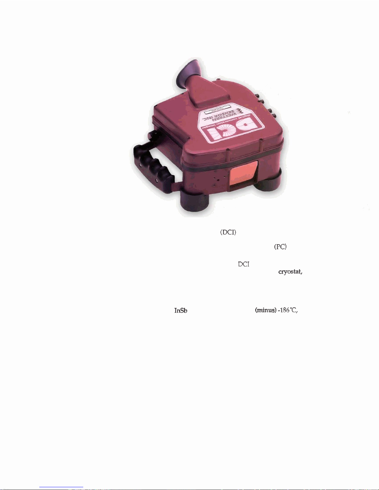
The Digital Conversion Imager
(DCI)
is a hand-held infrared imager
used to view and store frames of infrared images. At a later time, the
frames can
be
downloaded
to
a personal computer
(PC)
for viewing,
converting to other formats, and printing.
To view and collect infrared data, the
DCI
uses a sensor array system
consisting of a mirror scanner, infrared detector and
cryostat, signal
processing electronics, and visual display. Rechargeable nicad battery
packs power the electronics and a motor drive that rotates a ten
-
sided
mirror assembly at
1200
rpm.
Argon gas provides the cooling for the infrared detector. This array of
linear infrared
InSb detectors, gas-cooled to (minus)
-186C
converts
infrared radiation received by the optical system into electrical signals.
After processing and amplification, these signals produce visible images
that are reconstructions of the infrared patterns of the scene.
The coolant for the detector is supplied from a refillable argon cylinder
attached to the bottom of the case.
Page 8
December
2,1993
Features
In addition to the standard features of a hand-held, infrared imager,
specific features of the DCI include:
Snap-shot storage
-
30
frames of frame data with battery backup,
On-screen readouts - temperature target sight, frame
#,
auto or
manual temperature range setting, range, and battery monitor.
Snapshot data storage - Ambient temperature, time, date, frame
number, emissivity, and target temperature are stored with the
infrared frame.
On-screen temperature readout - auto and manual readouts of
temperature ranges.
Download data -serial transmission of frame image data to a PC.
The features of the DCI
FrameGrabber program ~nning on the PC
include:
Disk storage of data.
Conversion of snapshots to
TIFF,
the industry standard graphics file
format for graphics programs and word processors.
Conversion of data to PCL-5TM grayscale laser printer format.
Conversion of data for B&W/Color video monitors.
Print gray scale image plus a data file with ambient temperature,
time, date, framenumber, emissivity, and target temperature.
Dlgltal Conversion Imager User's Gulde
Page 9
December
2,1993
Inspection
Open the carrying case and examine the contents for any evidence of
damage. In addition to the DCI, the contents include:
Argon cylinders
Battery charger(s) with spliters
Safety strap
Nicad batteries
Pressure gauge
Wrench
The argon cylinders are fully pressurized. Do not open a cylinder until it
has been securely attached to the DCI.
Attaching the cylinder
Before operating the DCI, become familiar with the Warnings, Cautions,
and Notices at the beginning of this manual.
1.
Open the case and remove the DCI.
2.
Place the unit upside down on a smooth level surface (padded if
possible).
3.
Check the pressure of the argon cylinder with a gauge.
4.
Attach the cylinder to the unit.
a.
Open the latch on the stainless steel strap and lay the cylinder in
the cradle.
b. Align the cylinder so that the valve outlet is engaged with the
high
-
pressure nut.
c.
Close the stainless steel band and
&cure.
d. Finger tighten the high-pressure fitting nut to the cylinder.
5.
Tighten the high-pressure fitting nut.
CAUTION:
Do not over tighten the high
-
pressure fitting nut.
For a compression-type (gyrolok value), use a 9/16inch wrench to
tighten the high
-
pressure fitting nut 1/4 turn (snug only).
For an O
-
ring fitting, tighten with 11/16-inch wrench
6.
Open the argon gas valve one turn counter clockwise and listen for a
hissing
(DCI cool down period).
7.
Ensure that the hissing stops after 6 to
20
seconds and that no frost
forms on the valve assembly.
8.
Attach half of the safety strap to the unit, loop the strap around your
neck, and attach the second half of the strap.
CAUTION:
Do not use the
DCI
without the safety strap.
Dropping the unit may cause serious damage.
Go to the Startup instructions.
Digital Conversion Imager User's Gulde
Page 10

December
2,1993
Operation
The
DCI
has two modes for viewing temperature ranges:
Manual
allows you to select one of seven settings that range from
+10'C (50°F) to +500eC (900-F) above ambient temperature.
Auto
automatically selects the temperature range based on the
temperature
in
the target at the centex of the screen.
Each range has 255 levels that are recorded in the image snapshot. Along
with the image the following data is also captured
and
stored:
Frame number
Ambient Temperature
Target Temperature
Date
Time
Digital
Conversion
Imager User's Guide
Page 11
December
2,1993
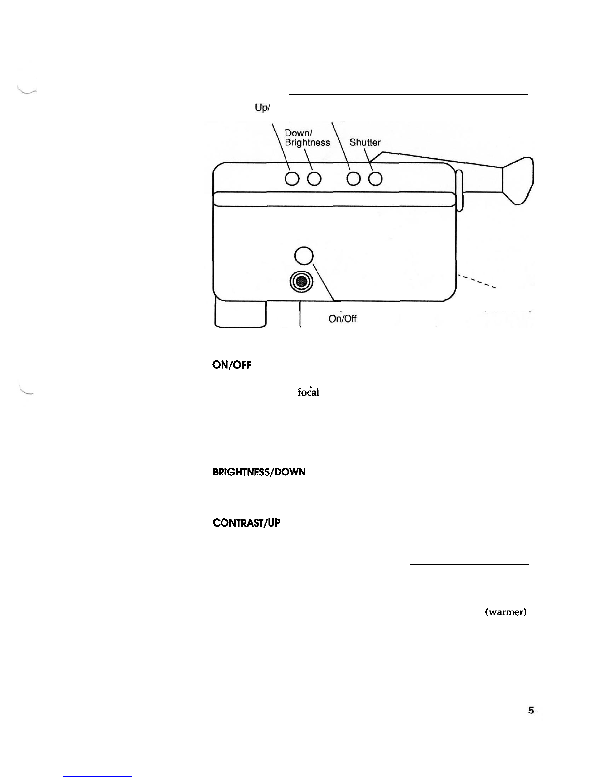
DCI Controls
UP/
Contrast
Menu
I
J
F
O
CUS
I
\
(not
shown)
Connector
for
cable
from
PC
ON/OFF
connects and disconnects the batteries to the scanning drive
motor and the electronics of the
DCI.
FOCUS
adjusts the foGa1 length of the infrared imager to sharpen the
image on the screen.
SHUTTER
captures the infrared snapshot in the viewer. Also brings you
back to the scanning screen.
MENU
brings up the Main Menu where you can select the temperature
range; Celsius, Fahrenheit, or view only; and emissivity.
BRIGHTNESSIDOWN
adjusts the image threshold for the current
temperature range. Brightness can
be
adjusted to include or exclude a
temperature level within the ranges. Also used to make range, scale,
emissivity settings.
CONTRASTIUP
adjusts the intensity of the infrared image in the viewer.
Also
used to make range, scale, emissivity settings.
Brightness and Contrast Controls
Here's an example of how to use the Brightness and Contrast keys to
look for heat leaks on a roof. Set the Contrast to its lowest setting and
then adjust the Brightness until the roof just begins to appear in the
viewer. At this range of brightness only those objects brighter
(warmer)
than the roof will show in the viewer. To intensify the temperature
readings in the view that are slightly higher than the roof, increase the
Contrast.
Digital Conversion imager
User's
Guide
Page 12
December
2,1993
Starting and Operating
the
DCI
1.
Turn the ON/OFF switch to ON and check for unusual noises or
clicking. (The whining noise of the motor is normal.)
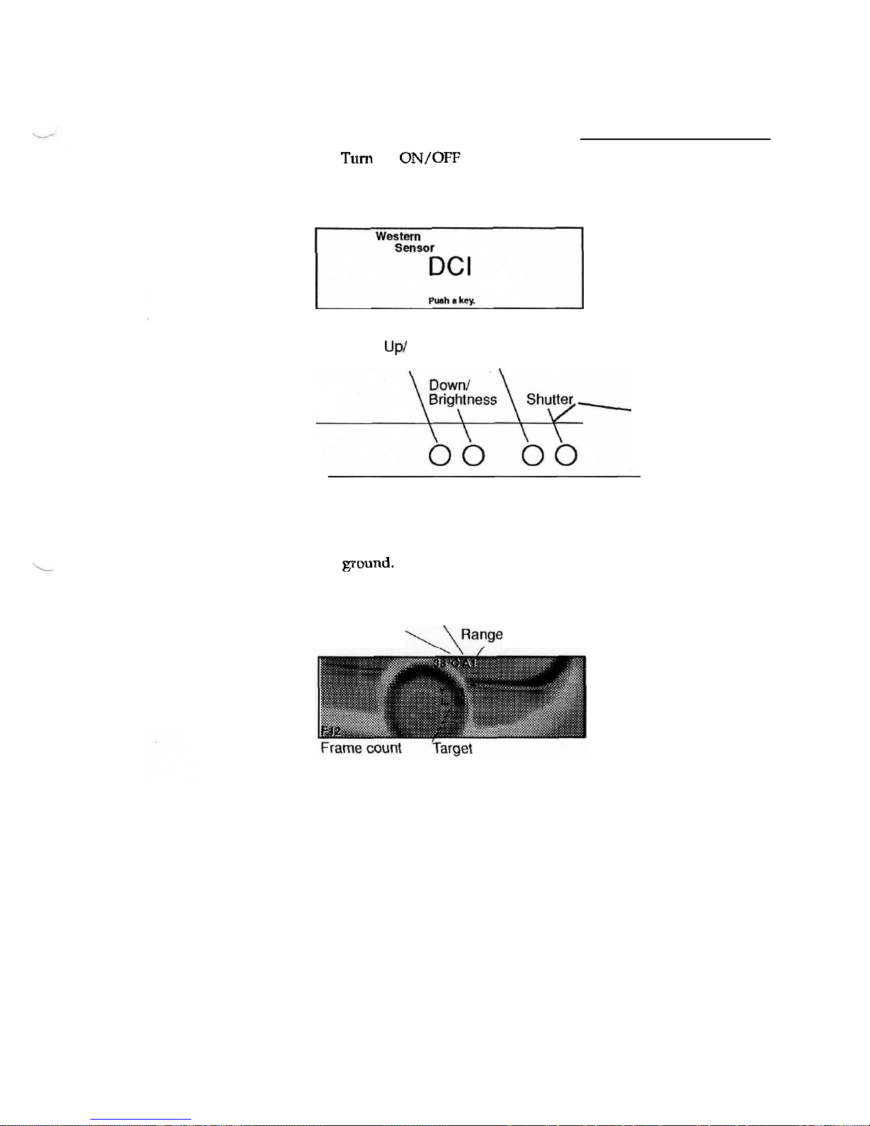
When you look through the eyepiece, you will
see
the initialization
screen. The initialization screen looks like this.
Western
Sensor
rT7-l
Push.
Lev
2.
Push any of the keys to bring up the scanning screen.
u
PI
Contrast
Menu
-
-
3.
Select a target (such as a person or distinct object) and focus until the
image becomes sharp.
In this example, a car tire is being scanned. The white area under the
car is the heat from the engine that has been deposited on the
vound.
Auto or
Manual
Target mode The target temperature, the
temperature
mode, and the range appear at
the top center of the frame.
The frame number appears in
the lower left corner. The
target in the center of the
screen locates the target
temperature
If an up or down arrow appears instead of the temperature, then the
temperature reading is above or below the range that has been
set
in
manual mode.
Dlgltal Converslon Imager User's Gulde
Page 13
December
2,1993
4.
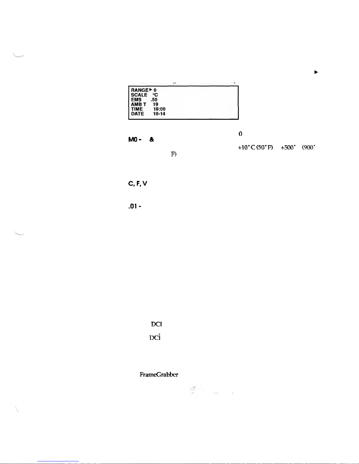
Push the Menu key to bring up the Main Menu screen which
contains range, scale, emissivity, ambient temperature, time and
date.
With the Main Menu on the screen, the Menu key cycles the arrow
'
between Range, Scale, and Emissivity.
Range
Temperature ranges with 0 being the lowest
and
6
MO
-
6,
(L
A
being the highest. In manual mode, there are seven
temperature ranges from
+IO'C
(50'
F)
to
+500e
C
(9CHS
Fl
above ambient. In auto mode, the range is selected
automatically based on the temperature in the target at
the center of the screen.
Scale
Celsius, Fahrenheit, and View. In View mode there is
c,
F,
v
no target and no temperature readout on the screen.
Frames will have temperature data when printed.
Emissivity
The ratio of radiation intensity from a surface to the
.01 - 1.00
radiation intensity at the same wavelength from a
blackbody at the same temperature.
5.
With the arrow pointing
to
Range, use the Up and Down keys to
cycle through the temperature ranges, or select Auto mode.
With the arrow pointing to Scale or Emissivity, use the
Up
and
Down keys to cycle through the available selections.
6.
Push the Shutter key to return to the scanning screen.
7.
Push the Shutter button to freeze the image in the viewer.
The word SAVE? appears above the frame number.
8.
Review the image to ensure that it contains the
data
you want.
9.
Press the Shutter button again. The frame number increments and
the image is saved. If you don't want to save the image, press the
Menu button.
The
DCI goes back to scanning and the image is not saved to
memory. The frozen screen has a time
-
out and
if
no action is taken,
the
DC~
returns to scanning.
After
30
frames have been saved, the word Full appears on the
screen. You can continue to scan, but you can not save frames.
Before you can save additional frames, you must download the
frames to a
PC
and reset the frame counter. Refer to the section on
FrameGrabber for more information.
Digital Conversion imager User's Guide
Page 14
December
2.1993
Selecting Ranges
When you select the Auto mode, the
DCI
uses the appropriate range for
correct temperature calculations based on the source inside the target
area of the scanning screen. To select one of the seven ranges
(0
-
6),
move the arrow with the Menu key until it points to Range. Then use the
Up and Down keys to select the temperature range of the area you want
to scan.
Selecting Scale
Select C for Celsius temperature readout, F for Fahrenheit temperature
readout, or V for View mode which removes the temperature readout
from the scanning screen.
Selecting Emissivity
Select the emissivity reading that is appropriate for the material you are
looking at. Refer to Appendix A for emissivity readings for common
materials.
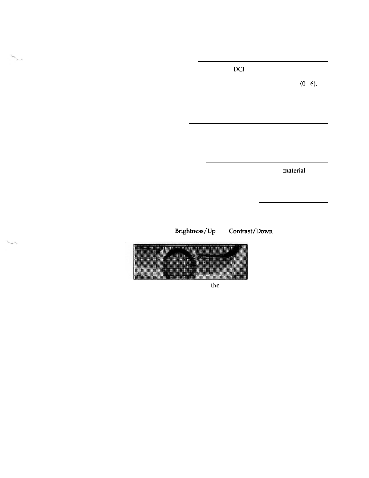
Adjusting Brightness and Contrast
When you push the Brightness or Contrast button in the scanning screen,
a scale appears along the top of the viewer with a B to indicate
Brightness or a C to indicate Contrast. With the scale at the top of the
screen, use the
Brightness/Up and Contrast/Down keys to adjust the
scale. As you press the buttons a small indicator moves across the scale.
To return to scanning, press
the Shutter key. The Brightness and Contrast
screens have time
-
outs, and if no action is taken, the DCI returns to
scanning.
Digital Conversion Imager User's Guide
Page 15
December
2,1993
Batteries
When the battery (Batt) indicator appears in the lower right comer of the
screen, the batteries are nearing the end of their useful charge. The
DCI
will continue to operate, however the rechargeable batteries should be
replaced soon.
Replacing discharged batteries
1.
Set the ON/OFF switch to OFF.
2. Place the
DCI
on its top, upside down.
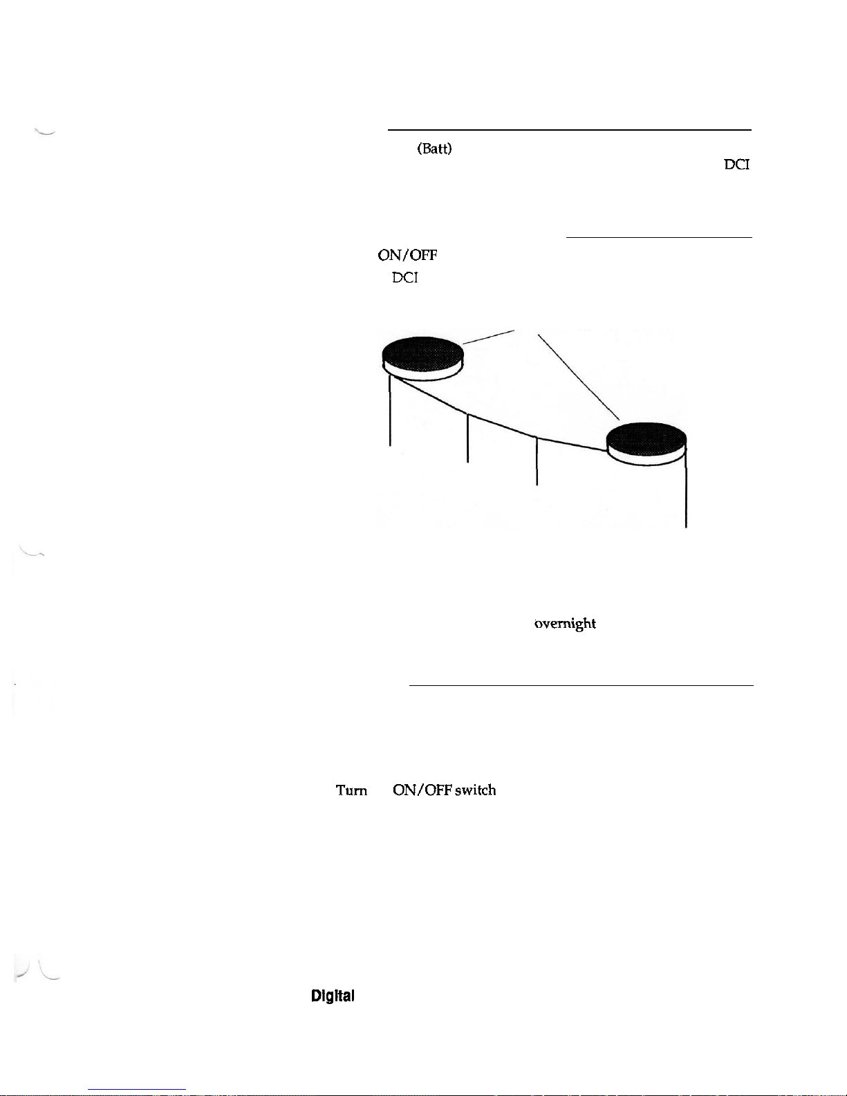
3.
Remove the covers on the batterycompartments.
Access to rechargeable batteries
4.
Carefully remove the batteries and disconnect them.
5.
Connect a fully charged set of batteries and carefully lower them into
the battery compartments.
6.
Replace the battery covers.
7.
Charge the discharged batteries overnight (12
-
14
hours maximum).
Do not overcharge the batteries.
Shut down
At the end of operations or when the picture begins to fade, shut down
the
DCI.
When the picture begins to fade, it indicates that the argon
cylinder is nearing empty. Do not allow the argon cylinder to become
completely empty. This permits air and moisture to enter the cylinder
which can damage the cryostat.
1.
Turn the ON/OFFswitch OFF.
2.
Shut off the gas supply by turning the valve knob clockwise until the
valve is firmly seated.
Ensure that the gas supply is shut off completely before storing the
unit.
Dlgltal Conversion Imager User's Gulde
Page 16
December
2,1993
FrameGrabber
FrameGrabber is the program that
runs
on your PC. Use FrameGrabber
to set the time and date for the
DCI, and to upload, print, and view the
frames captured with the DCI.
Connect the DCI to the PC
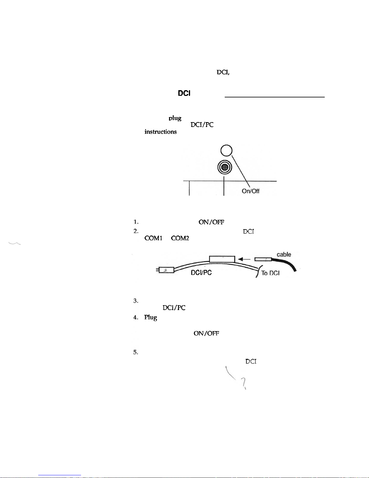
NOTE:
The steps in the following procedure must be performed in
numerical order. Do not plug the AC adapter plug into a wall outlet
until the
oluz on the wall transformer cable is inserted into the
.
-
connector on the DCI/PC serial cable. Failure to follow these
instmctions could cause the connectors to arc and cause personal
injury and/or damage your equipment.
connector
for cable
from PC
Ensure that the DCI
ON/OFF switch is set to OFF.
Connect the serial cable between the
DCI
cable connector and the
COMl or COM2 port on the back of the PC.
AC
adapter
DCIIPC serial cable
25
-
pin
D
connector
to PC
Insert the plug at the end of the AC adapter cable into the connector
on the
DCI/PC serial cable.
Plug the AC adapter plug into a wall outlet.
Power is automatically supplied to the DCI. You do not need to
switch on the DCI
ON/OFF switch.
Do not turn on the argon gas cylinder.
At the
DCI
initialization screen, press any key.
You must be at the view screen of the
DCI
to
download the frames or
set the DCI time and date.
Digital Conversion Imager
User's
Guide
Page 17
December 2,1993
Start
FrameGrabber
Turn
on
the
PC
and
start the
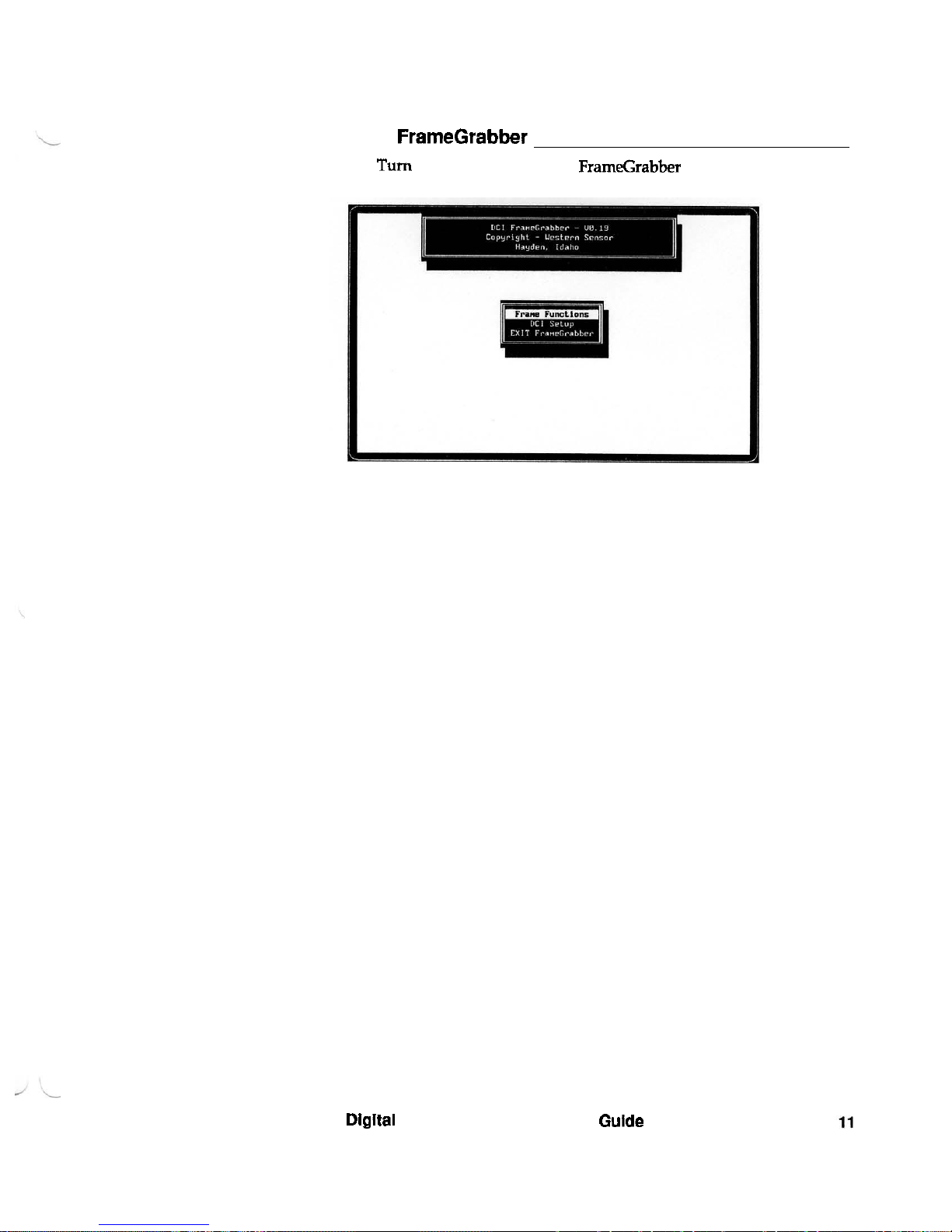
FrameGrabber program.
The
Main Menu looks like
this.
Dlgltal Conversion Imager User's Guide
Page 18
December
2,1993
DCI
Setup
Use the DCI Setup functions to set the time and date on the
DCI
and to
setup the COM port. You may need to set the time and date the first
time you use the DCI.
A
backup battery will keep the time and date
current after that.
When you select the COM port, the communications settings on the PC
such as baud rate and parity are set automatically to match the
DCI.
You
may have to re
-
select the
COM
port
if
you've used that port
on
you PC
for
a
modem or printer since the last time you downloaded files.
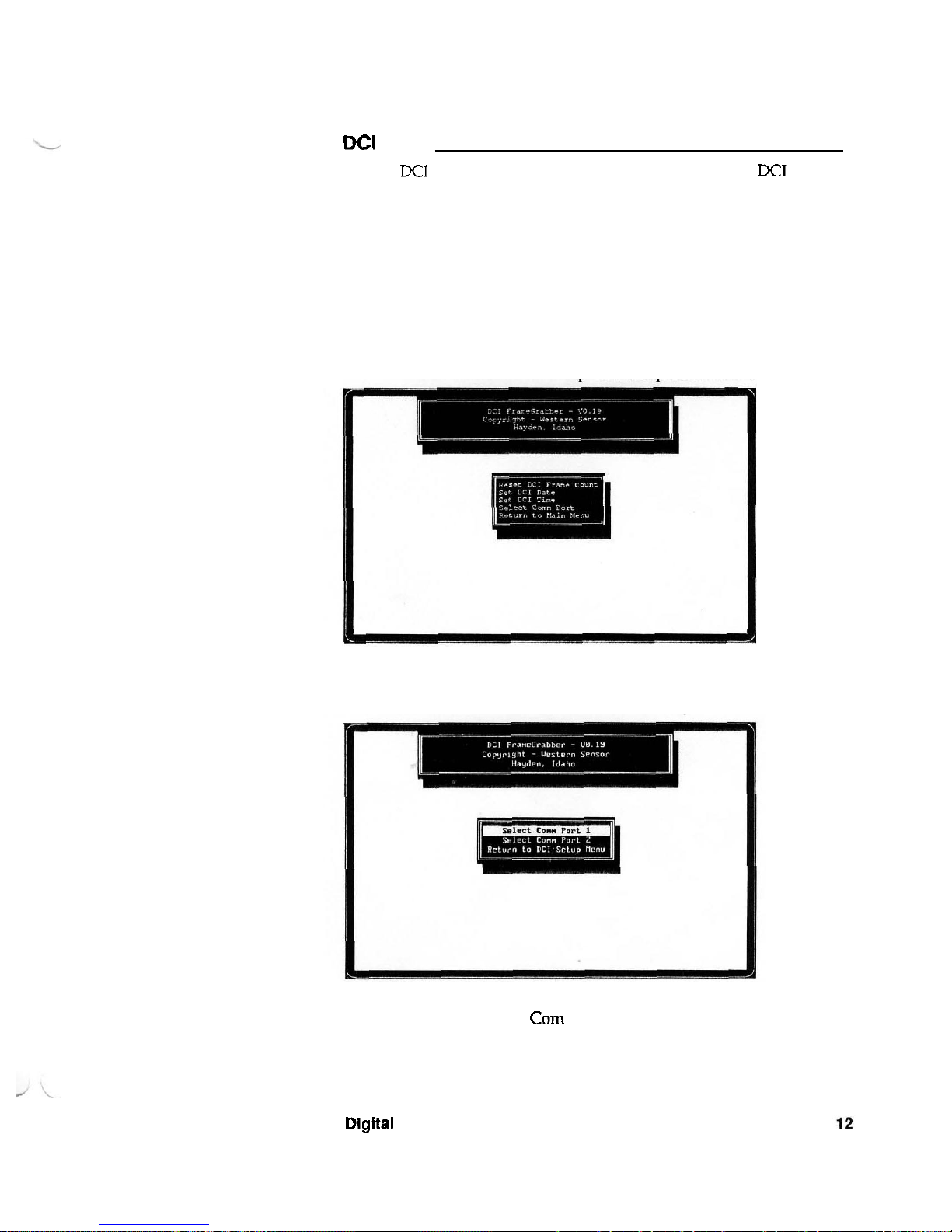
1.
Use the cursor (arrow) keys to move the highlight on the menu to
DCI Setup.
2.
Press Enter to select DCI Setup. The Setup Menu looks like this.
3.
Select the Com Port. The Com Port Menu looks like this.
4.
Select the appropriate Corn port.
5.
Return to the Setup Menu and set the date and the time.
Dlgttal Converslon Imager User's Gulde
Page 19
December
2,1993
Reset
DCI
Frame Count
Before you reset the
DQ
frame, ensure that you have uploaded the
frames
from the DCI
to
the PC that you want to save. Resetting the frame
count sets the frame number back to
1.
The frames are still there,
however, when you save a new frame in that slot number, it overwrites
the existing frame.
1.
Connect the serial cable between
the DCI cable connector and the
COMl or COM2 port on the
back of the PC.
2.
Turn the Power button on the
DCI
to
ON.
Do not
turn
on the
argon gas cylinder.
3.
At the DCI initialization screen,
Connector
for
cable
press any key.
igi74@
from
P
C
@I
%4<@&
f
6%
You must be at the view screen of the DCI
to
download the frames or
set the
DCI time and date.
4.
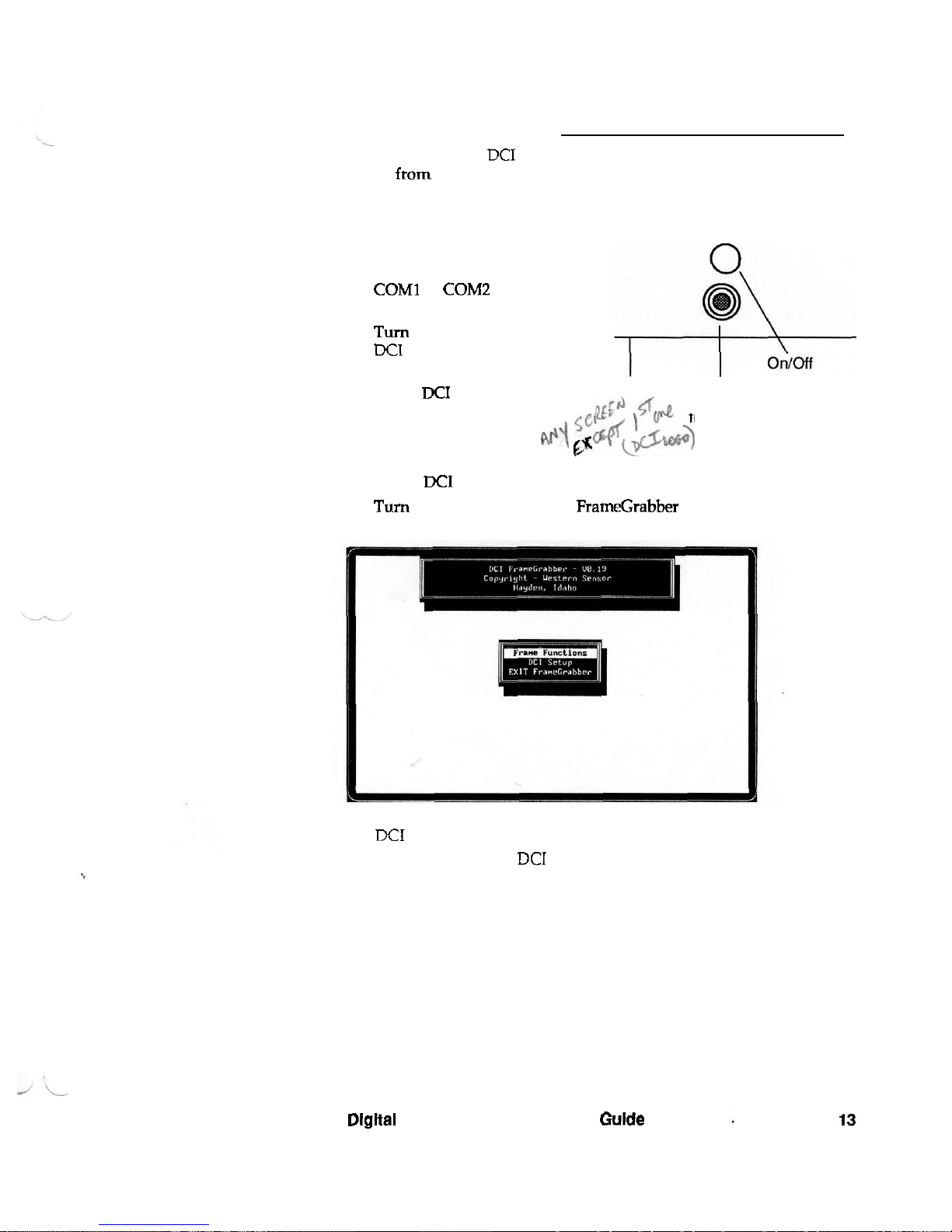
Turn on the PC and start the FrameGrabber program.
The Main Menu looks like this.
5.
Use the cursor (arrow) keys to move the highlight on the menu to
DCI
Setup.
6.
Press Enter to select
DCI
Setup. The Setup Menu looks like this.
Digltal Converslon Imager User's Guide
Page 20
December
2,1993
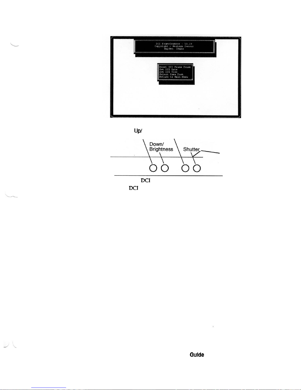
7.
Press Enter with the highlight on the Reset
DCI
Frame Count.
u
PI
Contrast Menu
8.
Go to the
DCI
and press the Shutter key.
The
DCI
prompts
SAVE?.
9.
Press the
DCI
Menu key.
The frame count rolls back
to
01.
Digital Conversion imager User's Gulde
Page 21
December
2,1993
Uploading
Frames
From
the
DCI
to the
PC
When a frame is uploaded from the
DCI
to a PC, it is stored in the PC's
memory.
If
power to your PC is interrupted, or if you leave the
FrameGrabber program, the frame stored in
memory
is lost.
You can print or view a stored frame, or you
can
save it to disk. When
the frame is stored to disk, the image is saved as a
.TIFF
file and the
ambient temperature, time, date, frame number, and target temperature
are saved
to
a data file with a
.HDR
extension or file
type.
Once frames are saved to disk, they must
be
recalled from disk and
placed back in memory before they
canbe viewed or printed with
FrarneCrabber.
1.
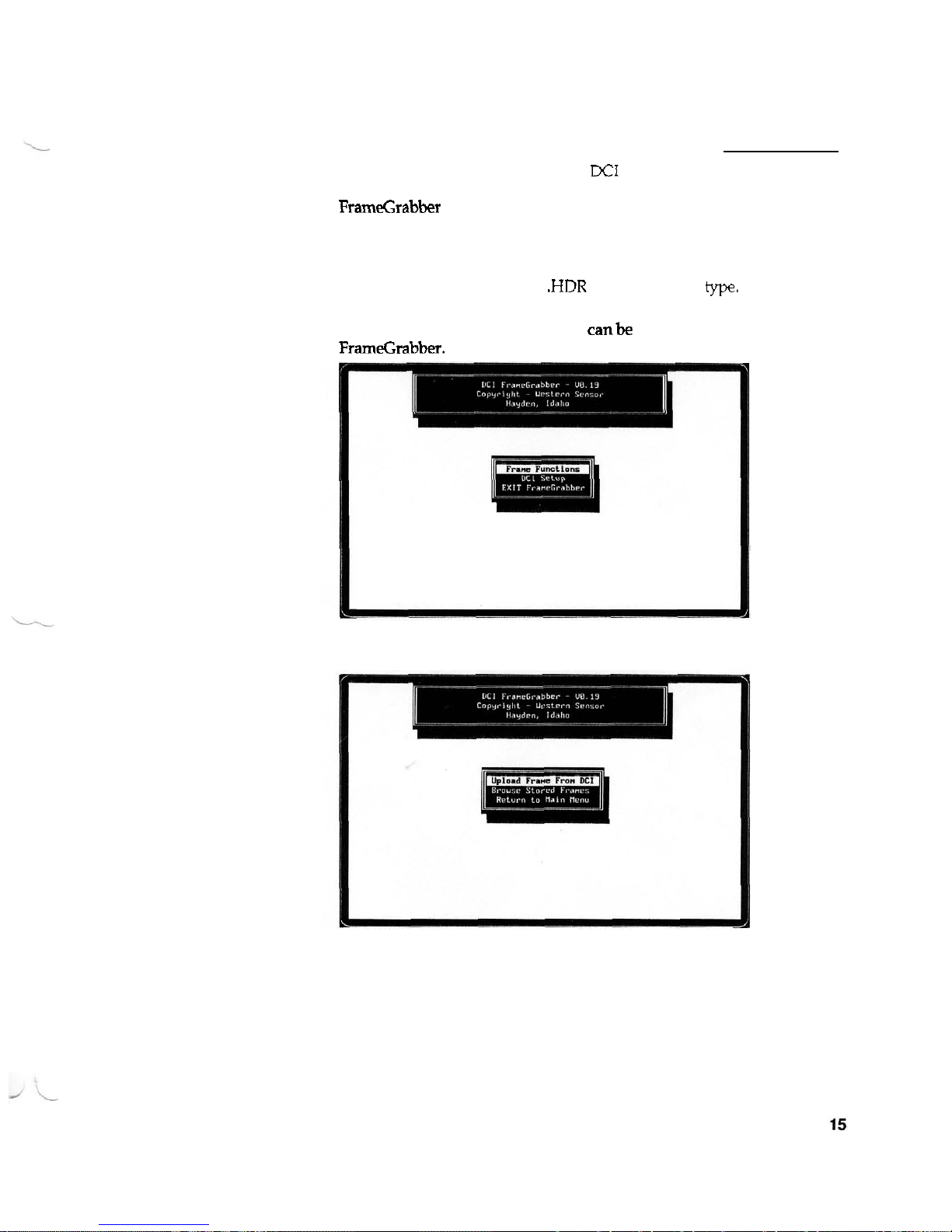
Select Frame Functions from the Main Menu.
The Frame Functions Menu looks like this.
2.
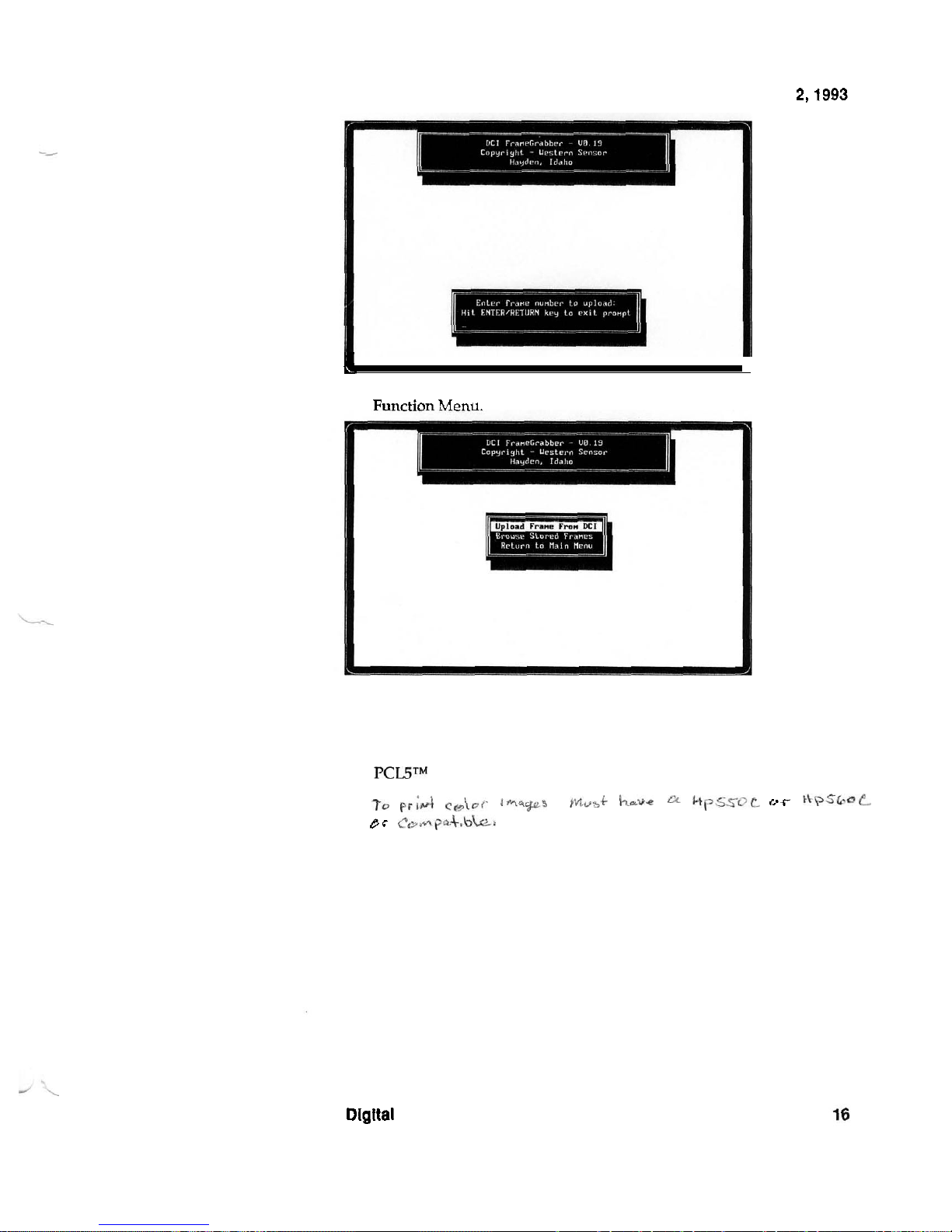
Select Upload Frame From
DCI.
3.
Enter the frame number of the image you want to upload to the PC,
and then press Enter.
Digital Conversion Imager User's Guide
Page 22
December
2,1993
n
a
4.
Press Enter instead of typing a frame number to return to the Frame
R~nrtion
Menu.
5.
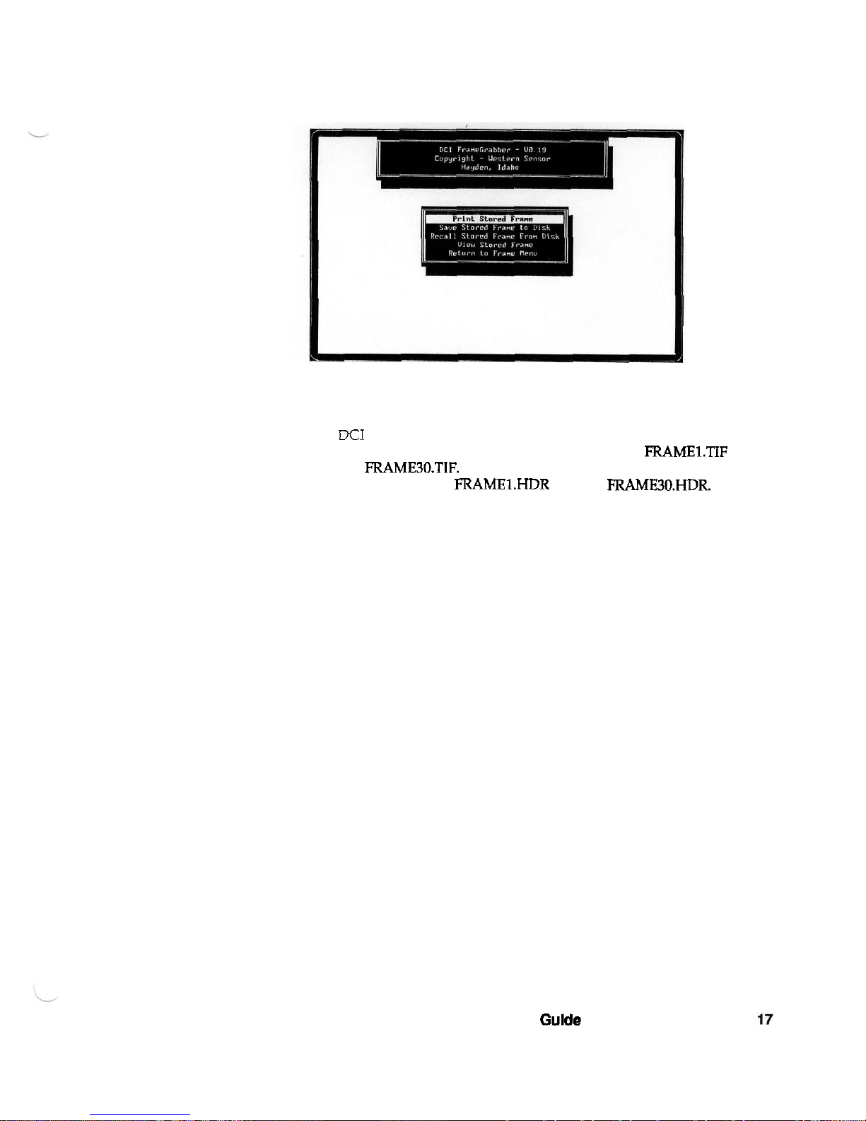
Select Browse Store Frames to print
or
view a frame, or to save a
frame to disk or recall a frame from disk.
To print the image files on a laser printer, the laser printer must be
PCLP
compatible.
to
pr;&
Ce\or
1m~~9-s
-
JMv~~
~UC
hpSSOL
oc
KPS~~L
gr
~w~fip*+.bb-
Dlgltal Conversion imager User's Guide
Page 23
December
2,1993
The Browse Stored Frames Menu looks like this.
After viewing a frame, press any key to return
to
the Browse Stored
Frame menu.
The
DCI
holds up to 30 frames. When the frames are uploaded and
saved to disk, the image data is saved in files named
FRAME1.TIF
through FRAME30.TIF. The time and temperature data associated with
each frame is saved as
FRAMELHDR through FRAME30.HDR. When
these files are saved to disk on the
PC,
make sure that you copy them to
another directory or to another floppy disk before you save files to disk
again.
Notice: If you save the image and header data to
a
directory with
existing frame data, the new files will replace the existing ones with the
same name.
Digital Conversion Imager User's Gulde
Page 24
December
2,1993
Haskel Booster
Pump
Refilling a cylinder with the Haskel booster
pump
-
The Haskel booster pump refilling system is the most commonly used
system to refill argon gas cylinders. Check with Western Sensor before
using another
type
of pump.
1.
Check the gas supply in an argon cylinder by opening the valve
slightly and listen for hissing (escaping gas).
The hissing means that the cylinder is refillable.
If
there is no
hissing, the cylinder needs evacuation. Send it to Western Sensor.
2.
Place the empty argon cylinder in the white holder.
3.
Thread the pressure line nut into the argoncylinder. Hand tighten
the nut, but allow it to
be
loose to enable argon gas to escape during
the bleeding sequence.
4. To bleed the high
-
pressure line, open the source tank valve slowly
and allow a small amount of gas to escape for
2
to
3
seconds.
5.
Close the in-line silver valve (from the source
tank
to the argon
cylinder) if the pump is
so
equipped.
6.
Firmly tighten the argon cylinder nut on the pressure line using a
9116
-
inch wrench for gyrolok-type valve; a 5/8-inch wrench for the
O
-
ring
type.
7.
Turn the pump ON/OFF switch to ON.
8. Open the in
-
line silver valve if the pump is so equipped.
9.
Open the empty argon cylinder valve.
10.
Using a 5/8-inch wrench, carefully tighten the packing nut under the
handle on the argon cylinder valve.
11.
Using a 3/8-inch wrench, tighten the acomnut
on
top
of
the argon
cylinder valve handle.
12.
During this time, the pump runs to
5,000
psi (cylinder full mark).
With a full Source tank
(2,400 psi), this takes
3
to
5 minutes. Refill
takes longer as the source pressure drops.
Digital Conversion Imager User's Guide
Page 25

December 2,1993
Removing a cylinder from the Haskel booster
pump
-
1.
Close the argon cylinder valve on the filled cylinder.
2.
Turn the ON/OFF switch on the pump to OFF.
3.
Close the in-line silver valve (if pump is
so
equipped.), or close the
source tank valve.
4.
Using a 9/16-inch wrench for a gyrolok-type valve and a 518-inch
wrench for an
O-ring type valve, loosen the nut on the high-pressure
line. (Some gas will escape.)
5.
Unthread the pressure line nut, freeing the filled argon cylinder from
the high
-
pressure line.
6. Mark the argon cylinder with a sticker showing
5,000 psi and the
date.
7.
Remove the filled cylinder from the white holder.
8.
Screw the protective cap on the valve fitting tbads to prevent
damage.
9.
When all cylinder refilling is complete, insert the protective plug in
the pump high
-
pressure line to prevent contamination.
10. Close the source
tank
value when you have finished.
Digital Conversion Imager User's Guide
Page 26
December
2,1993
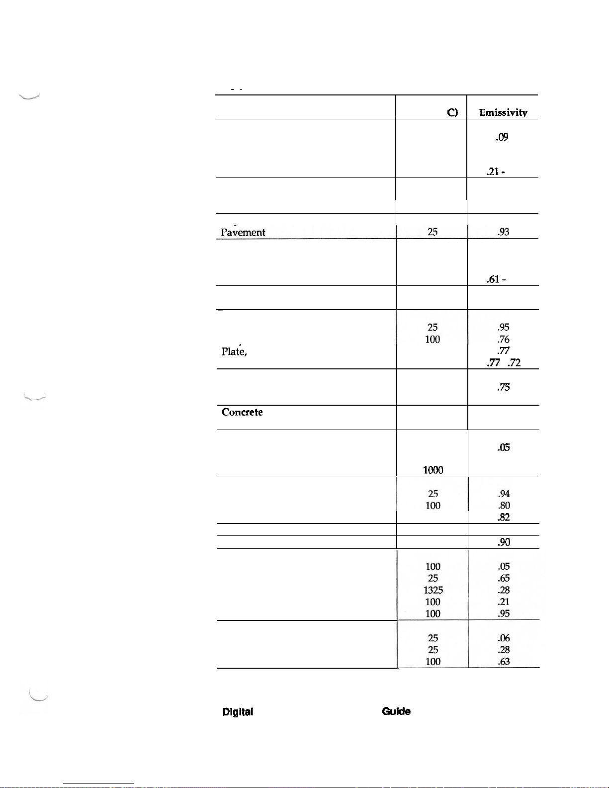
Appendix A Emissivity Settings
-
~
Paper
Approximate
Emissivity
.09
.55
.21
.21- .31
.%
Material
Aluminum
Commercial Sheet
Anodized Sheet
Heavily Oxidized
Increase with temperature
Asbestos
Board
Brass
Polished
Oxidized
Constant with temperature
-
Carbon
Lampblack
Graphite
Temperature
(Degrees
C)
100
100
100
100
-
500
25
Asphalt
25
Brick
Red
rough
.94
100
100
100
-
500
.61
.61
.61- .61
25
Plat'e, rough
Decrease slightly with temperature
Cloth
Cotton
Silk
.93
Concrete
Rough
Glass
Smooth
Convex
D
100
100
-
500
25
25
Copper
Polished
Heavily oxidized
Molten
.77
77
-
72
.75
.76
25
Iron
Polished
Rusted
Molten
Cast iron polished
Cast iron oxidized
Lead
Pure polished
Gray oxidized
Oxidized
.94
100
25
10M)
Nonex
Gravel
Gypsum
Dlgital Conversion Imager User's Gulde
20
.05
.78
.16
100
25
25
.82
.30
.90
Page 27
December
2,1993
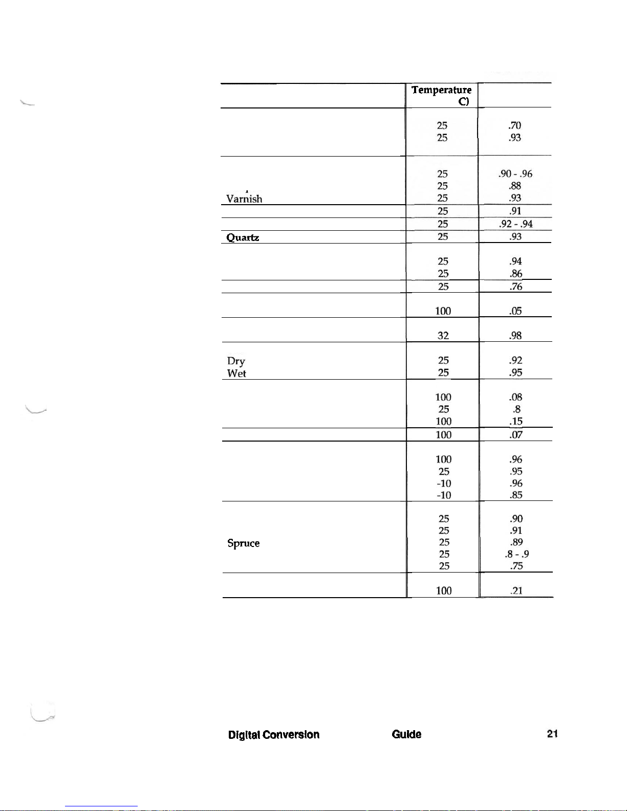
Material
Marble
Smooth
Polished
Paints
All kinds
Lacauers
vanhsh
Plaster
Paper
Quartz
Rubber
Hard black
Soft gray
Sand
Silver
Polished
Skin
Human
Soil
wet
Steel
Polished
Oxidized
Stainless
Tin
Water
Boiling
Drinking
Ice
Snow
Wood
Oak
Beech
Spmce
Plywoods
Sawdust
Zinc
Galvanized
Temperature
(Degrees
C)
Dlgltal
Conversion
Imager
User's Gulde
Approximate
Emissivity
 Loading...