

Page 1
Page 2

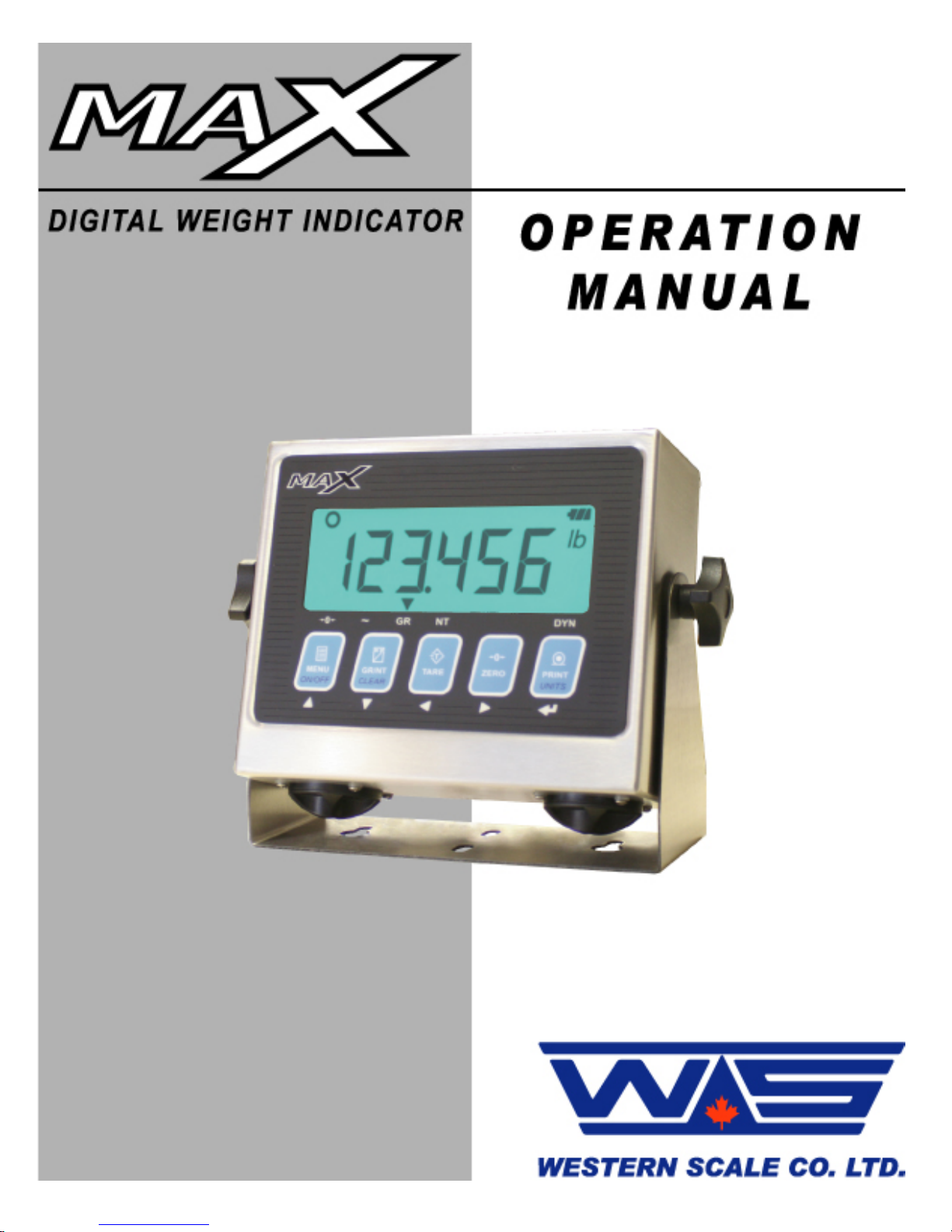
MAX DIGITAL WEIGHT INDICATOR
OPERATION MANUAL
SOFTWARE RELEASE 5.03, 04/2011
Copyright © 2007 - 2011 Western Scale Co. Limited. All rights reserved.
Published by: Western Scale Co. Limited.
Information in this Operation Manual is subject to change without notice due to
correction or enhancement. The information described in this manual is the
property of Western Scale Co. Ltd. No part of this manual may be reproduced or
retransmitted in any form without the expressed written permission of Western
Scale Co. Ltd.
Western Scale Co. Limited
1670 Kingsway Avenue
Port Coquitlam, B.C.
CANADA
V3C 3Y9
Tel: (604) 941-3474
Fax: (604) 941-4020
FOR TECHNICAL SUPPORT REGARDING THIS PRODUCT, PLEASE CALL
YOUR AUTHORIZED WESTERN DEALER:
Page 3

l
Operation Manua
TABLE OF CONTENTS
TABLE OF CONTENTS .................................................................................................................. 1
INTRODUCTION ............................................................................................................................. 2
Safety .......................................................................................................................................... 2
Features ...................................................................................................................................... 3
Specifications .............................................................................................................................. 3
DISPLAY & ANNUNCIATORS ........................................................................................................ 4
Weight Display ............................................................................................................................ 4
Arrow Annunciators ..................................................................................................................... 4
Display Annunciators................................................................................................................... 5
KEYPAD & SCALE FUNCTIONS.................................................................................................... 6
INSTALLATION ............................................................................................................................... 8
Pre-Installation ............................................................................................................................ 8
Mounting Instructions .................................................................................................................. 8
Plugging In .................................................................................................................................. 8
Loading Batteries ........................................................................................................................ 9
OPERATION (WEIGHING MODE)................................................................................................ 10
Start-Up ..................................................................................................................................... 10
Basic Weighing.......................................................................................................................... 10
Weigh Using a Tare (Containers, Pallets, etc.)......................................................................... 11
COMMUNICATIONS ..................................................................................................................... 12
Print a Ticket ............................................................................................................................. 12
User Menu................................................................................................................................. 13
Livestock Shrinkage .................................................................................................................. 14
TIME & DATE ................................................................................................................................ 15
OPERATION (REMOTE DISPLAY MODE) .................................................................................. 16
Display & Annunciators ............................................................................................................. 16
Start-Up ..................................................................................................................................... 16
Remote Keypad Functions........................................................................................................ 17
TROUBLESHOOTING & ERROR MESSAGES............................................................................ 18
1
Page 4
Digital Indicator
INTRODUCTION
The MAX digital weight indicator has been specifically designed for mobile
weighing applications. Multiple power inputs, a versatile display, and a weatherproof enclosure allow for efficient and trouble-free scale operation in any location.
Sophisticated filtering algorithms and display modes offer the best solution
available for vibration issues and dynamic applications such as livestock
weighing.
Built from the ground up with battery-friendly components, the MAX incorporates
Western’s unique PowerMAX operating platform that intelligently identifies when
to supply or conserve power resources. This industry leading power efficiency
stretches battery life to over 500 hours! Designed with the durability,
functionality, and versatility expected from Western, the MAX is truly engineered
for the diversity of the weighing industry.
The following information is for the exclusive use of WESTERN Dealers and
Customers.
Safety
Installation, configuration, and servicing are only to be done by qualified Scale
Service Technicians as authorized by Western.
Power must be disconnected before servicing the unit. Disconnection from the
line voltage is done by disconnecting the mains plug.
This equipment must be connected to a socket-outlet with a protective earthing
connection. The socket outlet shall be installed near the equipment, and shall be
easily accessible.
This equipment is intended for connection to multiple RATED VOLTAGES or
FREQUENCIES. The switchover to the corresponding voltage is done
automatically by the equipment.
CAUTION! HIGH VOLTAGES are present inside the MAX
indicator enclosure.
Scale Service Technicians handling MAX PCBs must observe
proper electrostatic discharge (ESD) handling procedures.
ATTENTION! Unauthorized installation and service of this unit
may void the warranty.
2
Page 5

l
Features
Mobile & Versatile
• Large LCD display
• Easy to read in low light and direct light conditions
• Weather-proof, stainless steel enclosure suitable for outdoor use
• MENU key accesses tickets and macro functions
Multiple Power Inputs
• Direct AC Power
• 4 “D” cell alkaline batteries (Up to 500 hours)
• 12 Volt input terminal for car batteries and power adapters
Easy to Use & Service
• Flashlight style battery compartments
• Easy to navigate software menu and calibration
• Calibrate to any test weight value
• Terminal wiring
Advanced Capabilities & Quality
• DYNArrest digital filtering system for fast and stable dynamic weighing
• MACRO II Ticket System for customized scale tickets
• Made In Canada with 2 Year Warranty.
Specifications
1-1/8
Excitation: 5 VDC, Up to 4 x 350 Ω load cells (8 x 700 Ω)
Analog Input Range: 0 - 39 mV
Resolution: 1 million (Internal counts)
10,000d Class III / IIIL (NTEP);
10,000d Class III; 20,000d Class IIIHD (M. Can.)
Measurement Speed: 10 - 80 weight samples/sec. (Automatic)
Power: Battery: 4 "D" cell alkaline batteries
AC Input: 90 - 240 VAC
DC Input: 12 VDC
Consumption: 500 mW (Rated 5W)
Display: 6 digit, 7 segment, LCD display with backlight
th
inch digits (29 mm)
Communications: Full duplex RS-232 serial port
Configurable data format
Selectable output strings & tickets
Temperature Range: 14°F to 104°F / -10°C to 40°C
Approvals: NTEP & Measurement Canada Approved
Operation Manua
3
Page 6
Digital Indicator
DISPLAY & ANNUNCIATORS
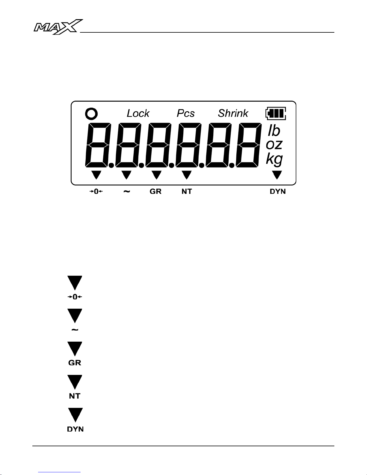
The MAX uses a Liquid Crystal Display (LCD) with an LED backlight. HTN
technology gives the display better contrast over wider viewing angles. LCD
arrow and display annunciators communicate scale status and mode information
to the user.
MAX Display
Weight Display
• 6 digits (7 segments each). Up to 3 decimal points.
• Negative weights are indicated by a minus sign (-) on the far left character.
Arrow Annunciators
CENTRE ZERO: The scale is within ±0.2 graduations of TRUE
ZERO.
MOTION: The scale is IN MOTION (the weight is changing).
GROSS: The scale is in GROSS weighing mode.
NET: The scale is in NET weighing mode (a tare weight is stored).
DYNAMIC: The scale is weighing in DYNAMIC mode (if enabled).
4
Page 7
l
Operation Manua
Display Annunciators
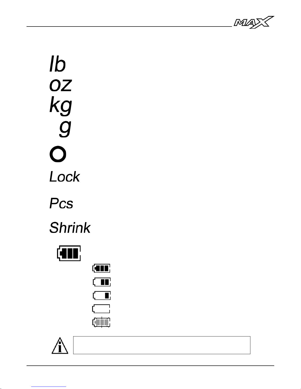
Scale is weighing in POUNDS.
Scale is weighing in OUNCES.
Scale is weighing in KILOGRAMS.
Scale is weighing in GRAMS.
The weight on the scale is STABLE.
The averaged scale weight has been LOCKED on the
display (only if dynamic weighing is enabled).
The indicator is displaying a PIECE COUNT. Not available at
this time.
The indicator is displaying a SHRINKAGE weight.
Indicates that the BATTERY IS IN USE & BATTERY LIFE
3 segments = Full battery life
2 segments = Med battery life
1 segment = Low battery
0 segments = Change batteries as soon as possible
Flashing = Batteries are too low for indicator to run
Some annunciators may not function the same way in Remote
Display Mode. For more information, see page 16.
5
Page 8
Digital Indicator
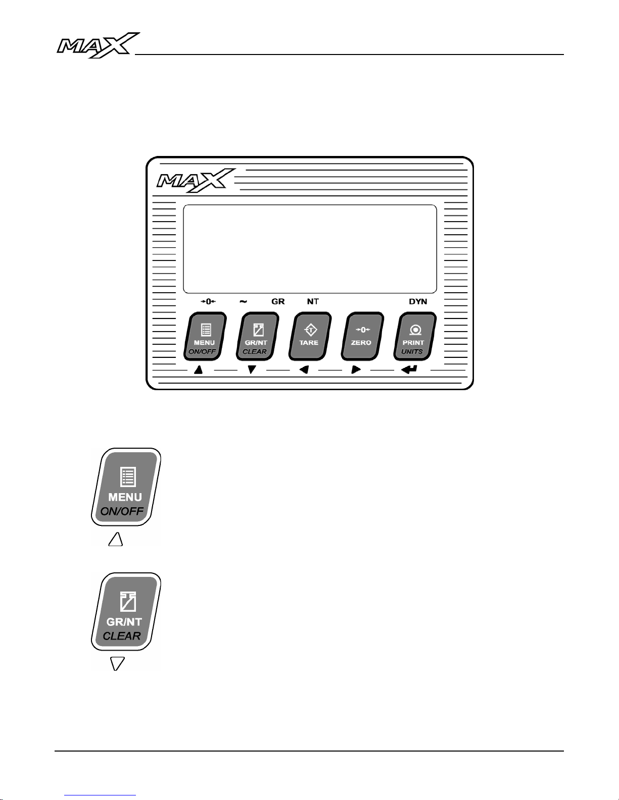
KEYPAD & SCALE FUNCTIONS
The MAX indicator utilizes 5 keys for operator interfacing. To maximize indicator
functionality, some keys perform multiple functions.
MAX Keypad
Press the key:
MENU - Cycles through the USER MENU to
access additional Scale Tickets and
functions (See page 13).
Press & hold
POWER - Turns the indicator ON and OFF
the key (2 sec):
Press the key:
GR/NT - Toggles between GROSS and NET
weighing modes if a tare value is stored.
Press & hold
the key (2 sec):
CLEAR - Clears any previously acquired tare
values. When used in Legal for Trade
applications, tares can only be cleared when
GROSS weight is at no load.
Clears Peak Hold (locked weight) values
when Peak Hold function is enabled.
6
Page 9
l
Operation Manua
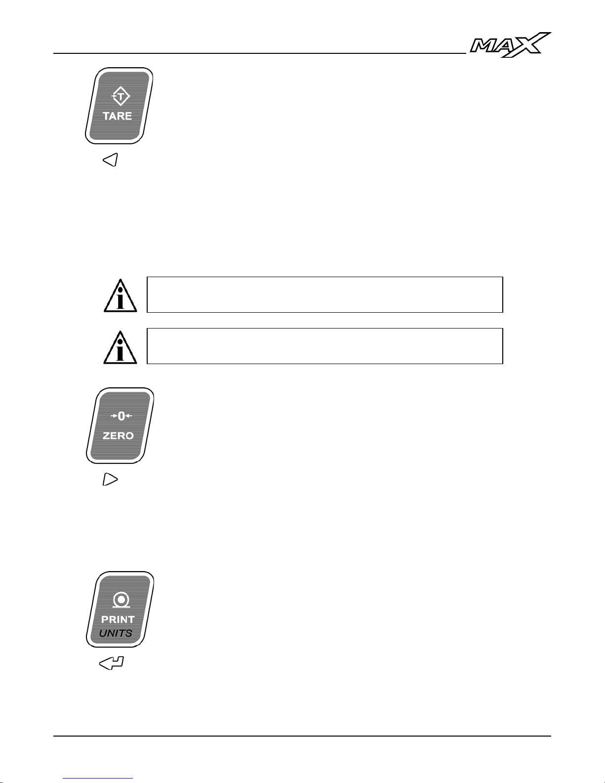
Press the key:
TARE - Acquires a tare value from weight on the
scale (Container, Box, etc.).
The indicator will not tare if:
• Scale weight is in MOTION;
• Scale weight is zero, negative or over capacity;
“Err 2” is briefly displayed when one of these
tare errors occurs.
Press & hold
the key (2 sec):
CLOCK – Display / Set the time and date. For
more information, see Time & Date (page 15).
The TARE button may be disabled in Calibration Mode by
Qualified Technicians.
In Canadian Legal for Trade applications, previous tare weights
must be cleared before a new tare weight can be acquired.
ZERO:
Sets the weight display to ZERO.
The indicator will not zero if:
• Scale weight exceeds the allowed ZERO RANGE;
• Scale weight is in MOTION or over capacity;
“Err 4” is briefly displayed when one of these zero
errors occurs.
Press the key:
PRINT - Transmits a scale ticket or data string.
NOTE: If multiple tickets are programmed, Ticket 1 is
always assigned to the PRINT key.
Press & hold
the key (2 sec):
UNITS - Toggles between Primary, Secondary and
Tertiary Weighing Units (if enabled).
Alternate Units may be selected or disabled in
Calibration Mode by Qualified Technicians.
7
Page 10
Digital Indicator
INSTALLATION
Pre-Installation
It is always good practice to verify that your Western MAX indicator is complete
and undamaged upon receipt.
• Check over packaging for any signs of damage.
• Remove the MAX from protective packaging and check for damage.
• Verify that the box includes the MAX indicator complete with:
o User Manual;
o Mounting bracket and thumb screws;
o Note: Batteries not included.
Mounting Instructions
1. The MAX can be mounted to horizontal or vertical surfaces using the
mounting bracket.
2. Ensure that mounting structures (walls, posts, etc.) will bear the weight of
the indicator (Approx. 3 kg / 7 lb with batteries).
3. Use proper hardware, including wall anchors where necessary, when
mounting the bracket and indicator.
Plugging In
1. Plug the AC power cord into a power outlet.
2. Installers must take proper steps to prevent noise, static, or other power
problems.
ATTENTION! In noisy industrial environments, powerconditioning filters are a requirement to ensure a fail-safe
operation under all conditions. Indicators should not share AC
power with electrical motors and switchgear. Consult the site
engineer for clean AC power.
CAUTION! HIGH VOLTAGE! Only trained personnel should
access any internal wiring and/or components.
8
Page 11
l
Operation Manua
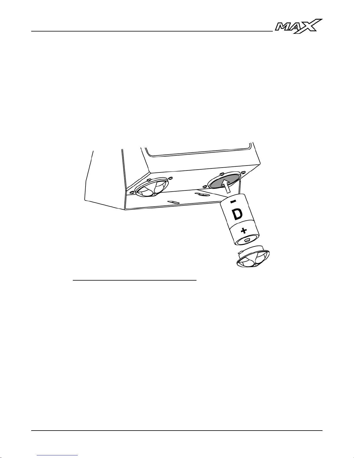
Loading Batteries
1. To open the battery compartments, turn compartment caps 90 degrees
counter clockwise.
2. Insert 2 “D” cell alkaline batteries in each compartment, checking for
correct polarity.
3. Replace battery compartment caps and turn 90 degrees clockwise to lock
the compartment closed.
PowerMAX Power Management System
The PowerMAX system automatically detects and prioritizes available
power sources to conserve batteries.
• If AC power is plugged in, it is the primary source with no draw on
the external 12 VDC power or the internal batteries.
• With no AC power, the external 12 VDC power is utilized with no
draw on the internal batteries.
• If AC and external 12 VDC power sources are not available, the
internal batteries are used.
9
Page 12
Digital Indicator
OPERATION (WEIGHING MODE)
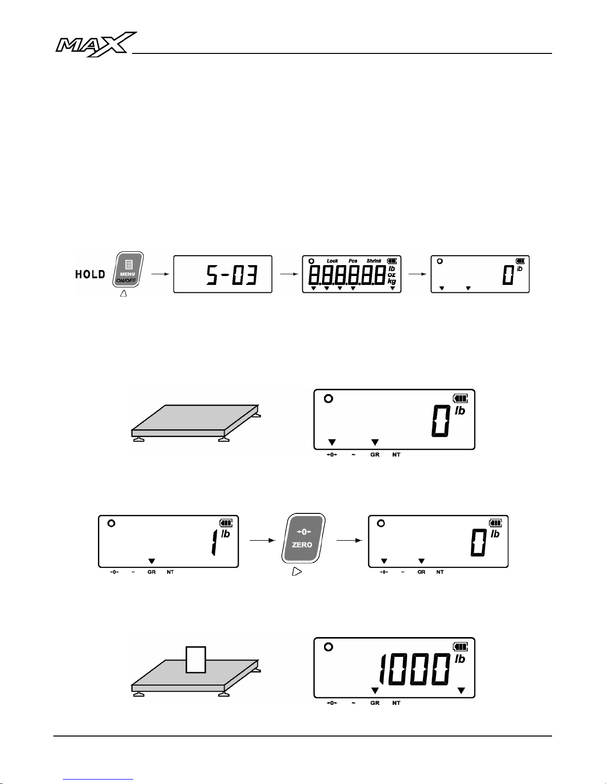
Start-Up
1. Ensure AC, external 12 volt, or battery power is being applied.
2. Press and hold the ON/OFF key.
3. The indicator will perform a short start-up sequence including the software
version number and a display segment test before entering Weighing
Mode (displaying the scale weight).
Basic Weighing
1. Ensure the weighing platform (scale) is empty and the indicator reads ‘0’.
2. If the indicator does not read ‘0’, press the ZERO key.
3. Load product on the scale and read the weight data on the indicator.
10
Page 13
l
Operation Manua
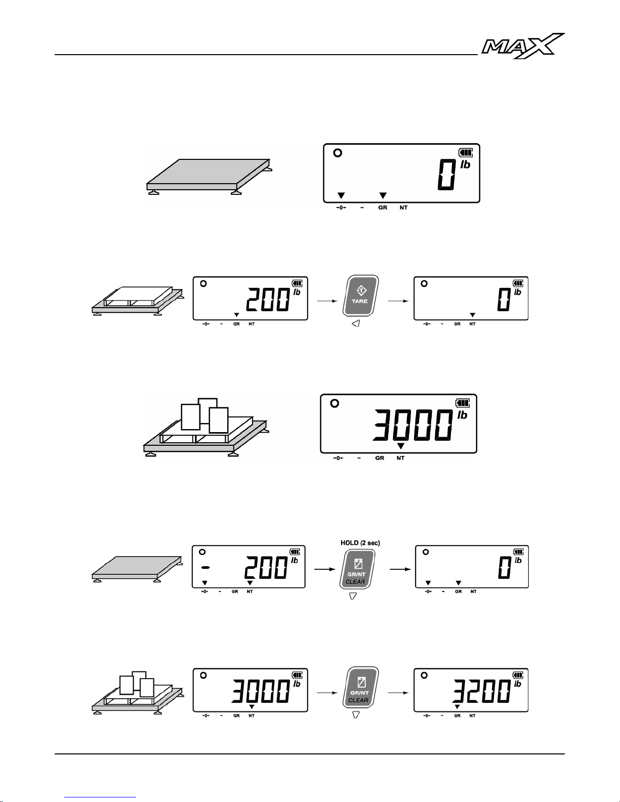
Weigh Using a Tare (Containers, Pallets, etc.)
1. Ensure the weighing platform (scale) is empty and the indicator reads ‘0’.
2. Load the container on the scale and press the TARE key. The indicator
will read ‘0’ and the NT annunciator (net weight) will be illuminated.
3. Load commodities into the container on the scale and read weight data on
the indicator.
4. To clear the tare, remove all weight from the scale. Press and hold the
CLEAR key until the indicator reads ‘0’ and the GR annunciator (gross
weight) is illuminated.
5. To view the gross weight when the scale is in net mode without clearing
the tare, press the GR/NT key.
11
Page 14
Digital Indicator
COMMUNICATIONS
Scale communications with peripheral devices such as serial printers, remote
displays and/or Personal Computers are configured by qualified Scale Service
Technicians during scale set-up and calibration.
Default Communications Settings:
• 9600 Baud • 1 Stop Bit
• No Parity • No Hardware Handshaking
• 8 Data Bits • Continuous Transmit
Default Communications Format:
Western Data String (DF1500)
<STX><P><W><W><W><W><W><W><W><S><U><U><S><M><M><S><ST><CR><LF>
STX: Start of Text (ASCII 02) M: Mode Character (GR or NT)
P: Polarity (- or Spc) ST: Status Character (Spc, O, M, or -)
W: Weight Character (# or Spc) CR: Carriage Return (ASCII 13)
S: Space (ASCII 32) LF: Line Feed (ASCII 10)
U: Units Characters (KG or LB)
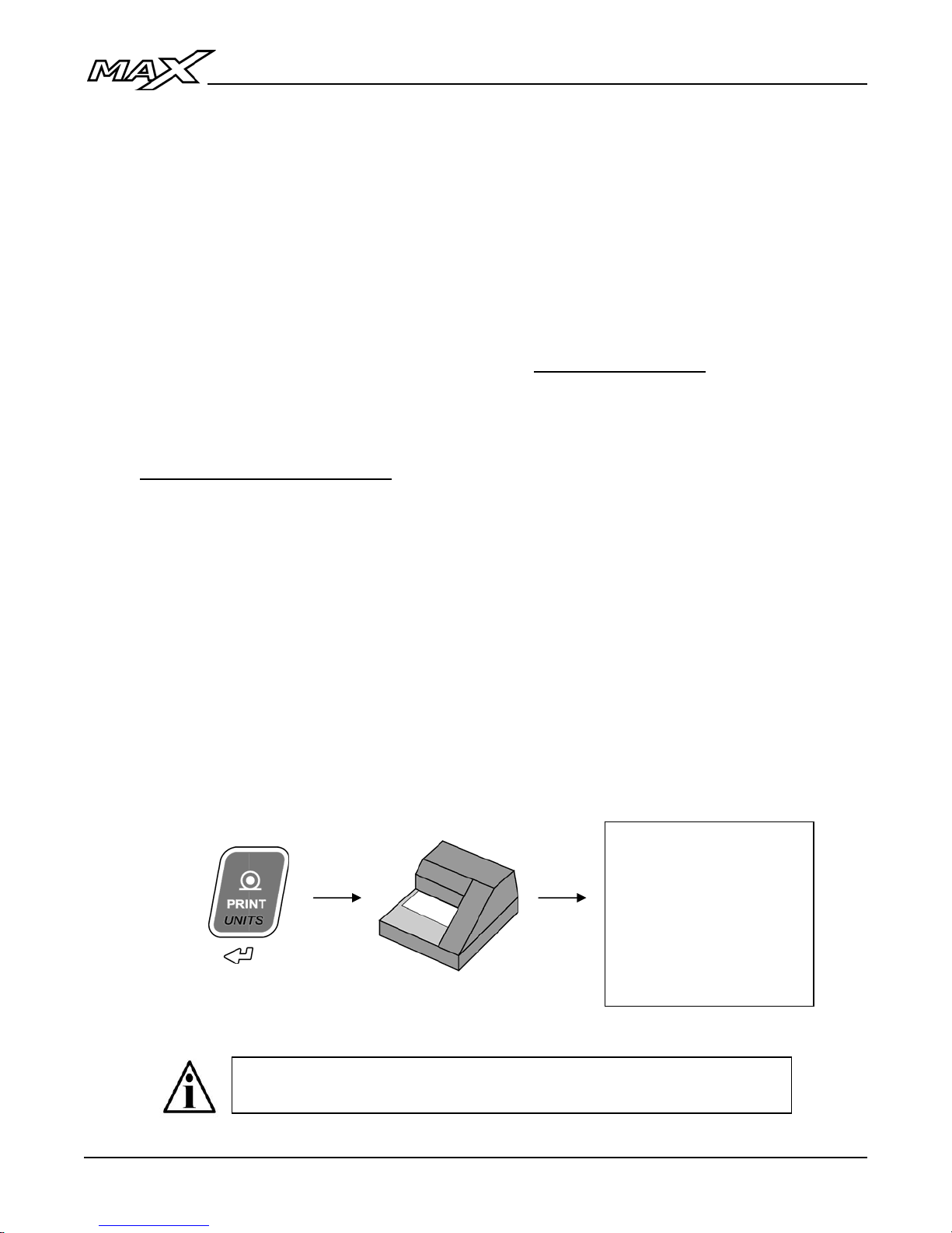
Print a Ticket
(If enabled)
1. Ensure the scale weight is stable.
2. Press the PRINT key to transmit a scale ticket to the printer.
10:36:10AM 04/22/11
Gross: 3200 lb
Tare: 200 lb
Net: 3000 lb
If multiple tickets are programmed, press the MENU key to enter
the User Menu to access these tickets and/or functions.
12
Page 15
l
Operation Manua
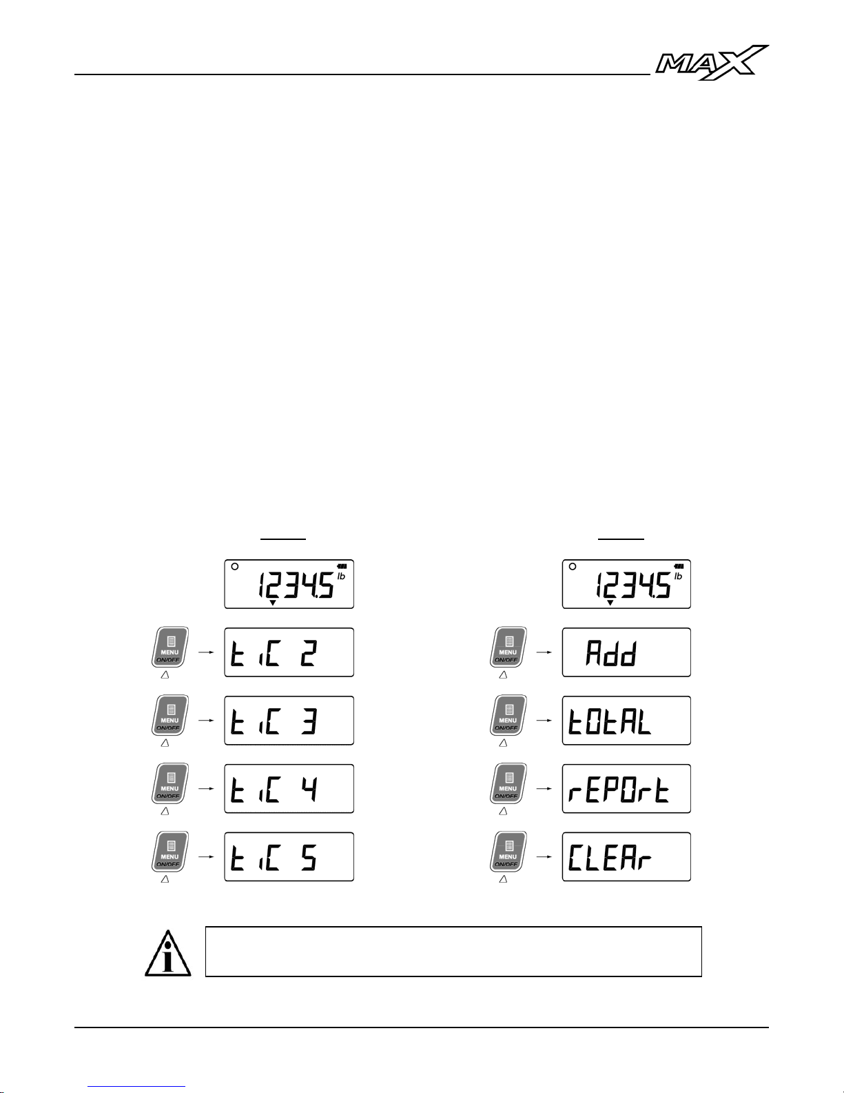
User Menu
The User Menu gives the Operator access to additional scale tickets and/or
indicator functions.
1. In Weighing Mode, press the MENU key to enter the User Menu.
• User Menu options (tickets) are numbered by default as in Fig. A.
• Tickets may be named to describe functions as in Fig. B.
• If there are no active tickets or functions, the User Menu will be
empty and the display will remain in Weighing Mode.
2. Use the UP & DOWN ARROW keys to cycle through the User Menu
functions.
3. When the desired menu item is displayed, press ENTER to activate it.
Once the function is complete, the display returns to Weighing Mode.
To return to Weighing Mode without activating a ticket or function, press
the LEFT ARROW key or wait 8 seconds for the User Menu to time out.
Fig. A Fig. B
User Menu options (tickets, functions, etc.) must be programmed
in Calibration Mode by qualified Technicians.
13
Page 16
Digital Indicator
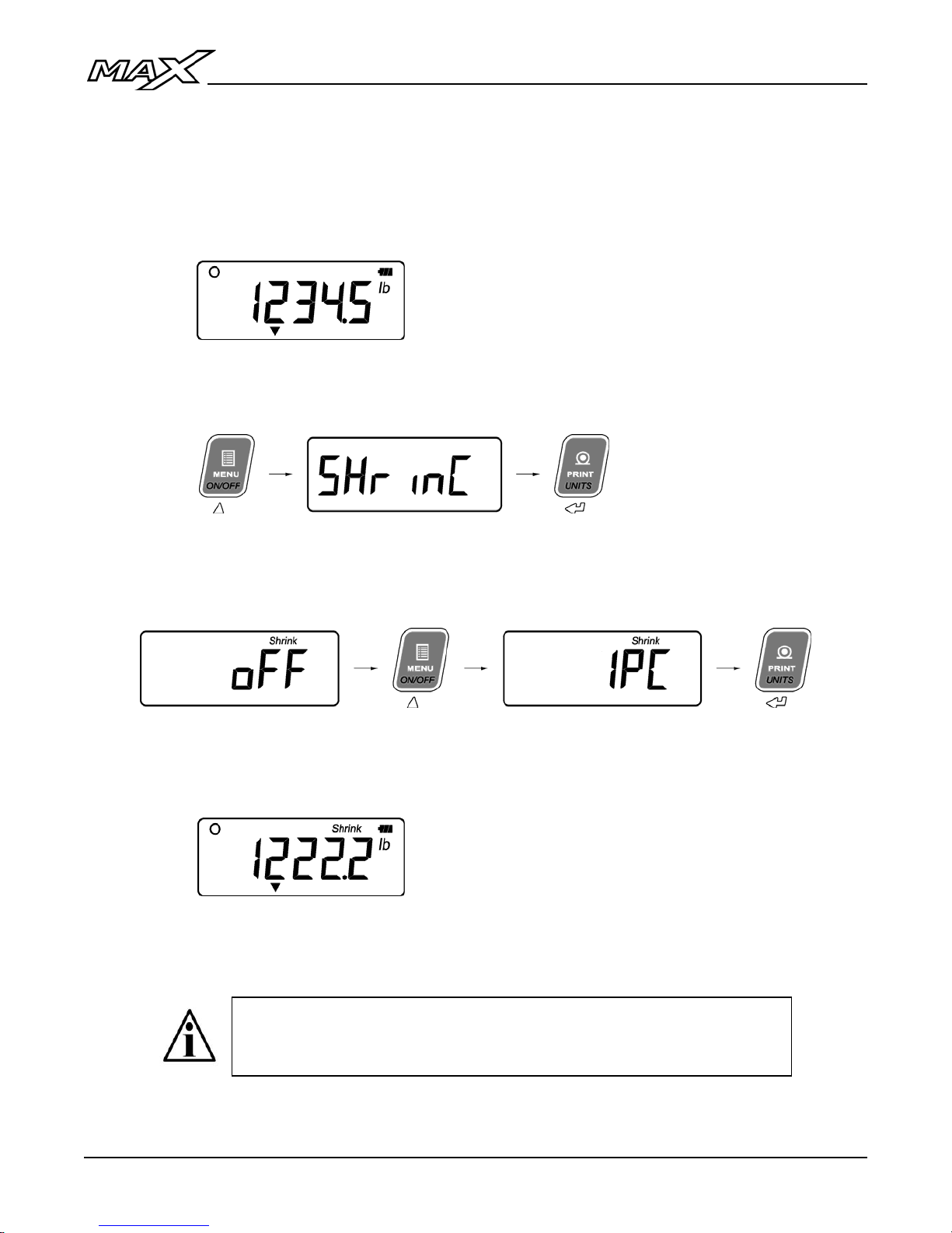
Livestock Shrinkage
The MAX features a livestock shrinkage program to compensate for potential
“weight loss” experienced during transport.
1. Load the livestock on the scale. The actual weight is displayed.
2. Press the MENU key until “SHrinC” is displayed. Press ENTER to
confirm.
3. Use the UP & DOWN ARROW keys to select the percentage to be used
for shrinkage (1 to 5%).
4. The display will show the shrinkage weight (actual weight minus the
percentage) and the “Shrink” annunciator will be illuminated.
5. To return to actual weight, set “SHrinC” to “OFF”. The “Shrink”
annunciator will be turned off.
The Shrinkage option will appear in the User Menu after the
tickets if enabled in Calibration Mode by qualified Technicians. If
not enabled, it will not appear in the User Menu at all.
14
Page 17
l
Operation Manua
TIME & DATE
1. From Weighing Mode, press and hold the TARE key until “CLOC” is
displayed, followed by the time.
• If 12 Hour Clock is selected, the time will appear HH.MM.A/P
• If 24 Hour Clock is selected, the time will appear HH.MM
2. Adjust the time using the LEFT & RIGHT ARROW keys to select digits
and the UP & DOWN ARROW keys to alter digits.
3. Press ENTER to confirm and the date will be displayed
• If International Date is selected, the date will appear DD.MM.YY
• If US Date is selected, the date will appear MM.DD.YY
4. Adjust the date using the LEFT & RIGHT ARROW keys to select digits
and the UP & DOWN ARROW keys to alter digits.
5. Press ENTER to confirm and return to Weighing Mode.
Time & Date must be enabled and the format (12 Hr, 24 Hr, etc.)
selected in Calibration Mode by qualified Technicians.
If the MAX is disconnected from AC power or another power
source, batteries must be installed for the clock to keep time.
15
Page 18
Digital Indicator
OPERATION (REMOTE DISPLAY MODE)
The MAX may function as a Remote Display when connected to other Western
indicators (Models M2000, MAX, Lightspeed & M1) by qualified Technicians. In
Remote Display Mode, the MAX displays the connected indicator’s weight and
scale status information.
Display & Annunciators
• The weight display should show the same weight numbers as the
connected indicator (complete with minus signs and decimals).
• Units and Mode annunciators will work. DYN, Centre of Zero, Pieces,
Shrinkage, Lock and battery level annunciators are not supported in
Remote Display Mode.
• Gram and Ounce annunciators will only work with M1, MAX or Lightspeed
indicators.
Start-Up
1. Ensure the AC power cord is plugged into a power outlet or that external
12 volt or battery power is being applied, then press and hold the ON/OFF
key.
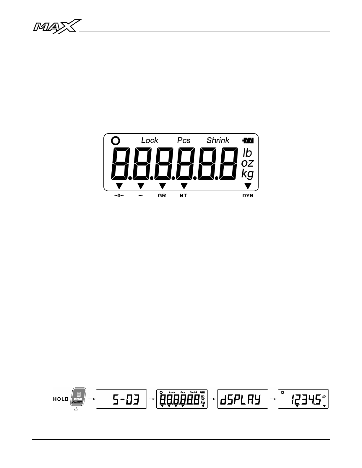
2. The start-up sequence displays the software version then the word
‘dSPLAY’ on the screen to indicate Remote Display Mode. The scale
weight from the connected indicator is then displayed.
16
Page 19
l
Operation Manua
Remote Keypad Functions
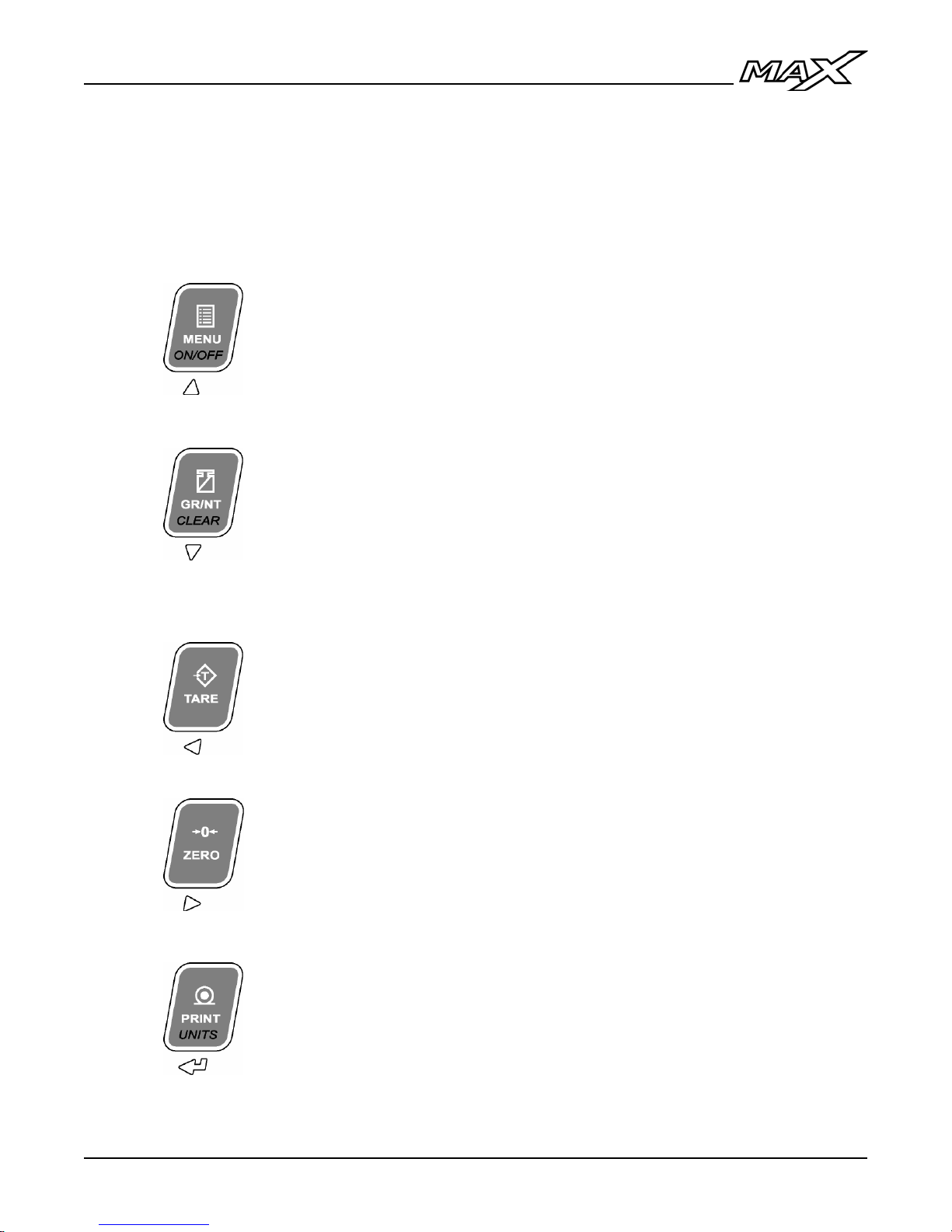
Remote Display Mode utilizes the keypad to send serial commands for remote
operation of indicator functions. To maximize functionality, some keys perform
multiple functions.
Press the key:
MENU – NO FUNCTION
Press & hold
the key (2 sec):
Press the key:
Press & hold
the key (2 sec):
TARE:
ZERO:
Press the key:
Press & hold
the key (2 sec):
ON / OFF – NO FUNCTION
GR/NT - Sends a serial command to toggle between
GROSS and NET weighing modes if a tare value is
stored (M2000 only).
CLEAR - Sends a serial command to clear any
previously stored tare values.
Sends a serial command to acquire a tare value from
the weight on the scale (Container, Box, etc.).
Sends a serial command to set the weight display to
ZERO.
PRINT - Sends a serial command to the indicator to
print a scale ticket.
UNITS - Sends a serial command to toggle between
Primary and Secondary Weighing Units.
17
Page 20
Digital Indicator
TROUBLESHOOTING & ERROR MESSAGES
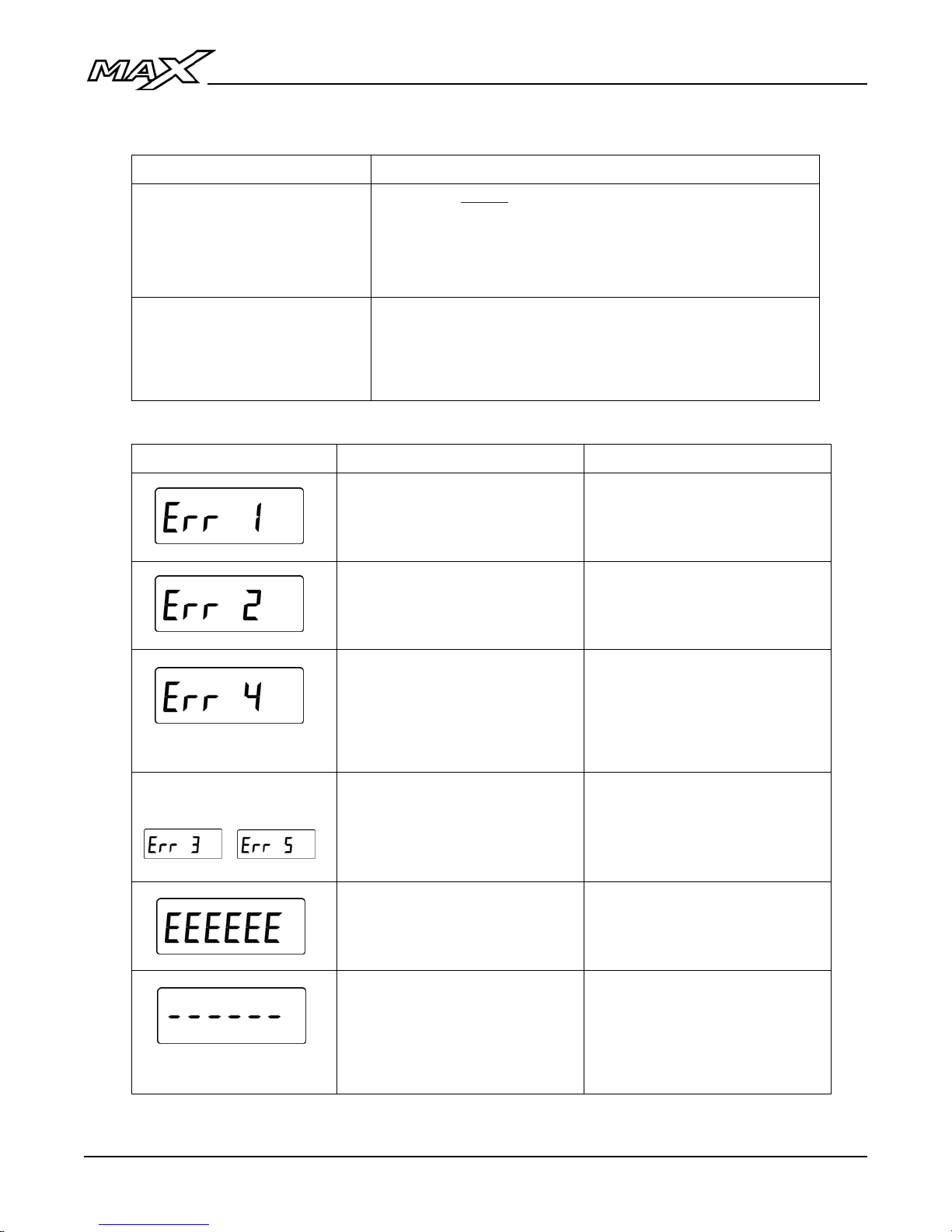
Unit won’t power up:
No Display:
Blank Display with
BLINKING battery symbol:
When using D Cell batteries (or C cells in older versions)
Press and HOLD the POWER key until indicator turns
on.
If the indicator does not turn on, verify the power source
(power outlet, batteries, etc.).
Battery power is too low for the indicator to function
properly.
• Replace batteries.
• Use alternate power source.
Error Message Condition Solution
Other Errors
Cannot print on motion or if
scale is overloaded.
Cannot TARE on motion or if
gross weight is at zero or
below zero.
Cannot ZERO scale outside
of zero range.
Scale Service Required
Scale Overload Error: Scale
weight is greater than scale
capacity.
Remote Display Mode:
Communications lost.
Wait for scale weight to settle
before attempting to print. If
overloaded, remove weight.
Place a weight on the scale
and wait for weight to settle
before attempting to tare.
Clean scale (debris may have
accumulated).
If problem persists, call your
local Scale Service Company.
Call your local Scale Service
Company.
Remove weight from scale.
Verify wiring/cable between
remote display and indicator.
If problem persists, call your
local Scale Service Company.
18
 Loading...