

Page 1
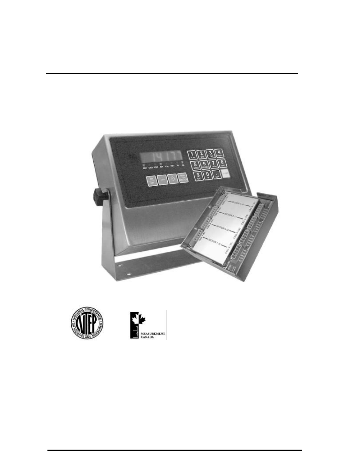
m2000D technical manual
high speed 3 channel digital indicator
Manual Release for V1.03D of software
We are continuously improving the manual and will send out updated versions as
soon as the manual has been finalized. More examples and features will be added.
JUNE 2002
Page 2

m2000D technical manual
M2000D WEIGHT INDICATOR TECHNICAL MANUAL
Copyright © 2002 Western Scale. All rights reserved.
Published by:
Western Scale
1670 Kingsway Avenue
Port Coquitlam B.C.
Canada
V3C 3Y9
Information in this technical manual is subject to change without notice due to
correction or enhancement. The information described in this manual is the property of
Western Scale. No part of this manual may be reproduced or transmitted in any form,
without the express written permission of Western Scale.
Western Scale Locations
Western Scale Co. Ltd.
1670 Kingsway Avenue
Port Coquitlam B.C.
Canada
V3C 3Y9
Wescale Inc.
Division of Western Scale
3873 Airport Way
Bellingham, WA.
98227 - 9754
INTERNET ADDRESS: www.westernscale.ca
Page I
Page 3

m2000D technical manual
GENERAL CABLE
DIGITAL SCALE ALLOCATION
GUIDE
q INTRODUCTION TO DLC SCALE ALLOCATION ……….
q GENERAL INSTALLATION GUIDE ………………………..
INTRODUCTION
GENERAL
INSTALLATION
q SECTIONAL SCALE INSTALLATONS……………………...
q HOPPER SCALE INSTALLATIONS ………………………..
q GENERAL ALLOCATION RELATED COMMANDS……...
q GENERAL CABLE CONNECTION GUIDE…………………
q GENERAL DIAGNOSTICS……………………………………
SECTION SCALE
INSTALLATIONS
HOPPER SCALE
INSTALLATIONS
GENERAL DLC
COMMANDS
CONNECTIONS
GENERAL
DIAGNOSTICS
Page II
Page 4

m2000D technical manual
CONTENTS
M2000D SYSTEM INTRODUCTION.......................................................................................................1
GENERAL OVERVIEW..........................................................................................................................1
MAIN FEATURES ..................................................................................................................................1
M2000D SYSTEM SPECIFICATIONS....................................................................................................2
M2000D DIGITAL SYSTEM DIAGRAM................................................................................................3
TYPES OF SCALE SYSTEMS SUPPORTED..........................................................................................4
DLC CHANNEL ALLOCATION.............................................................................................................4
SCALE SETUP USER INTERFACE........................................................................................................6
GENERAL INSTALLATION GUIDE......................................................................................................9
INTRODUCTION AND OVERVIEW......................................................................................................9
POWER SUPPLY CONNECTION...........................................................................................................9
LOAD CELL CONNECTION................................................................................................................10
SERIAL PORT CONNECTIONS...........................................................................................................10
DLC COMMUNICATIONS CABLE CONNECTIONS ..........................................................................10
SYSTEM GROUNDING ........................................................................................................................11
SECTIONAL SCALE INSTALLATION GUIDE................................................................................... 13
521 Assign a Sectional Scale: calibration command.........................................................................14
SECTIONAL EXAMPLE (1)...............................................................................................................15
SECTIONAL EXAMPLE (2)...............................................................................................................16
HOPPER SCALE INSTALLATION GUIDE..........................................................................................19
520 Assign a Hopper Scale: calibration command.............................................................................20
HOPPER EXAMPLE (1) .....................................................................................................................21
HOPPER EXAMPLE (2) .....................................................................................................................22
GENERAL ALLOCATION RELATED COMMANDS .........................................................................25
500 Clear All Remote DLC scale allocations : calibration command................................................25
501 Clear Scale 1 Allocation: calibration command........................................................................25
502 Clear Scale 2 Allocation: calibration command........................................................................25
503 Clear Scale 3 Allocation: calibration command......................................................................... 25
525 DLC Load Cell Masking: calibration command........................................................................26
530 Reset Corner Field adjustment entries: calibration command.....................................................27
531 Corner / Section Manual Span Adjustment: calibration command.............................................. 28
532 Auto Corner Span Adjustment: calibration command................................................................ 29
551 DLC communications Error Counter: Calibration command...................................................... 30
552 DLC Packet Counter: Calibration command..............................................................................30
Page III
Page 5

m2000D technical manual
555 DLC Software Upgrade Download: calibration command .........................................................31
556 Obtain DLC BIOS Firmware version information: calibration command ...................................31
557 Obtain DLC BOOT Firmware version information: calibration ................................................31
558 DLC Set AD Range For Active Corner: calibration command................................................... 32
592 Restore System Setup From DLC slave: calibration command...................................................33
591 Backup System Setup To a DLC slave: calibration command....................................................34
594 Reload Scale Allocation (field replacements): calibration command.......................................... 34
600 Scale Status/Diagnostics Information: non-calibration command...............................................36
620 DLC Slave Line Status: non-calibration command ....................................................................37
GENERAL CABLE CONNECTION GUIDE.........................................................................................39
M2000D INDICATOR CONNECTIONS ...............................................................................................39
DLC CONNECTIONS ...........................................................................................................................40
SINGLE DLC SLAVE CONNECTION.................................................................................................. 41
DUAL DLC SLAVE CONNECTION – TYPE 1.....................................................................................42
DUAL DLC SLAVE CONNECTION – TYPE 2.....................................................................................43
GENERAL DIAGNOSTICS.................................................................................................................... 44
DLC STATUS INDICATORS ................................................................................................................44
ERROR MESSAGES.............................................................................................................................47
Page IV
Page 6

m2000D technical manual
M2000D SYSTEM INTRODUCTION
GENERAL OVERVIEW
A M2000D weighing system consists of an indicator connected remotelly to one or two
DLC remote digital intelligent load cell terminal boxes, supporting up to 16 load cells.
A digital M2000D scale system provides for a high level of data integrity between the
scale platform and indicator for up to a 1000 feet apart. Because the analog scale data is
converted to digital data inside the remote DLC slave and send, as digital data to the
indicator, there is no data degradation across long cable runs. The digital system has a high
level of resistance to RFI /EMI interference, as required by industrial installations.
The M2000D system consists of an indicator and one or two DLC slave units. The DLC
slaves consist of 8 load cells per DLC. The digital system has no AD converters inside the
indicator itself. The M2000D supports 3 scale channels and calibration commands allow
the user to assign any or all of the load cells on the DLCs to a particular scale. A scale
assignment might consist of either a hopper or sectional scale configuration. These hopper
/ sectional scale groupings are then allocated to the 3 scales provided for by the M2000D
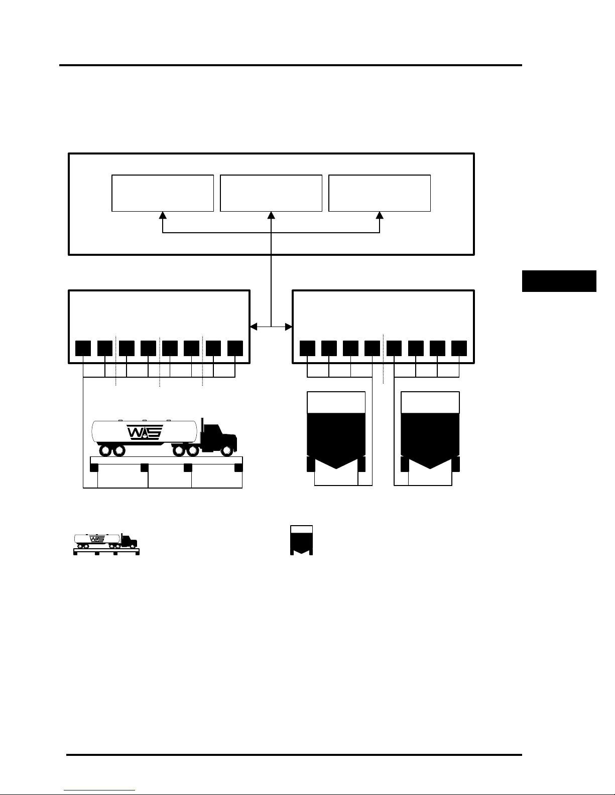
indicator – see Figure 1 for more detail.
INTRODUCTION
MAIN FEATURES
The M2000D Digital Indicator features include:
q Each DLC slave unit has 8 load cells that can be grouped to make up a scale
configuration. The M2000 Digital indicator supports up to 16 load cells.
q The system allows for a combination of hopper type and /or sectional scale allocations
q A DLC slave can be up to a 1000 feet from the indicator with no data degradation
q Each load cell converter has a programmable input range of 10,20,40 or 80mV
q Each load cell can produce a maximum of ±512 000 raw counts per converter
q The M2000 Digital system has an optically isolated communications interface
q The system has complete galvanic isolation between indicator and DLC remote slaves
for lightning protection
q Load cell inputs are factory matched for field interchangeability of DLC units
F
Page 1
Page 7

m2000D technical manual
M2000D SYSTEM SPECIFICATIONS
INDICATOR PERFORMANCE (Approved for Canada and USA )
Unit Conversion
Zero Tracking
Resolution
Sampling Rate
Span Stability
Zero Stability
Linearity Correction
Calibration Method
Calibration Sealing
Filtering
Modes
Firmware Upgrading
DLC remote load cells
Display
DLC LOAD CELL INPUTS
DLC Remote Load cells
Full Scale
Excitation
Resolution
DLC cable length
DLC current
Lbs/kg
1-99% of d or 1,2,3d
+/- 512 000 A/D counts per load cell
100 times a second per AD/ channel
2ppm/ Celsius
5nV/Celsius
5 span entries
Calibration through software stored in Flash memory
Class 1 Audit Trail System, password protected
FAST STEP quick response
Display from CH1,CH2,CH3 and Total of all Channels
Flash Memory - In field Firmware upgrading without affecting calibration data
16 Load cells using two DLC slaves
Red 0.75” 6 digit 7 Segment Display
8 AD converters per DLC remote slave
4 ranges 0-9mV, 0-19mV,0-39 and 0-79V
5VDC,16x350,32x700 ohm in total
+/- 512 000 A/D counts per load cell
500ft nominal or @ 1000 ft (22 AWG 2 pair / each pair shielded) with remote power
500mA per slave with 8 *350 ohm load cells connected per DLC slave
COMMUNICATIONS
Serial Outputs
IO Interface
External IO – Setpoints
External IO- Analog Output
External IO- Digital inputs
Networking
2 full duplex RS232/RS422
SMART WIRE perhiperal expansion - RS485 multidrop
6 channel setpoint via SMART WIRE (optional)
4-20mA board via SMART WIRE (optional)
6 optically isolated inputs via SMART WIRE (optional)
RS485 Multidrop Networking of up to 32 indicators as slaves
ELECTRICAL
Power Requirements
Temperature Range
12VDC 1.5A maximum
-10C to +40C
ENCLOSURES
M2000D-DT 6x9.75x2.5 Stainless Steel Desktop (External Power Supply)
M2000D-NSB Swivel Stand 7.25x10x3 Stainless Steel NEMA with mounting for one option board
M2000DNSS Light Weight 8x10x4 Stainless Steel NEMA with option board mounting plan
M2000D-NSS-1 Heavy Duty 8x10x4 Stainless Steel NEMA4 with option board mounting plan
APPROVALS
Canada
USA
Class III 10 000 Class IIIHD 25 000
NTEP Class III/IIIL 10 000
Page 2
Page 8
m2000D technical manual
Œ • Ž •
Œ • Ž •
1 2 3 4 5 6 7 8
1 2 3 4 5 6 7 8
M2000D DIGITAL SYSTEM DIAGRAM
M2000D DIGITAL INDICATOR
SCALE 1
Sectional (4 sections)
SCALE 2
Hopper(4 corners)
SCALE 3
Hopper (4 corners)
DLC (P)RIMARY DLC (S)ECONDARY
INTRODUCTION
SCALE 1
Figure 1: A M2000D Scale Configuration
SCALE 3SCALE 2
HOPPER SCALESECTIONAL SCALE
Page 3
Page 9

m2000D technical manual
TYPES OF SCALE SYSTEMS SUPPORTED
The M2000D targets two main types of industry scales, hopper and sectional scales.
Hopper scales consist of 2, 3 or 4 cells. In a hopper system each cell is usually referred to
as a corner. Each corner represents a load cell channel on the DLC slave. A hopper scale
can be assigned to any of the 3 scale channels of the M2000D indicator.
The service personnel have the ability to perform corner corrections (field corrections)
during calibration to compensate for small non-linear offsets in load cell values.
No access to the junction boxes are required to setup the system. All load cell corrections
are done in software as part of a calibration setup, from the M2000D indicator keyboard.
The system stores information in the DC slaves as part of a calibration.
The other type of scale targeted by the M2000D is the sectional scale as implemented in
vehicle scales. A sectional scale consists of 2 or more sections, of which each section
consists of two paired load cell channels. The service personnel have the ability to perform
corrections on a section by section basis or even on a corner basis if required.
DLC CHANNEL ALLOCATION
There can be a total of 2 DLC slaves in a digital system, referred to as the (P)rimary and
(S)econdary DLC slaves. The status LED on each slave indicates whether it is the
primary or secondary slave. Please consult the section on general diagnostics for more
information on the status LEDs .
The slaves are configured as (P)rimary or (S)econdary slave using the ID select jumper on
the DLC terminal box respectively.
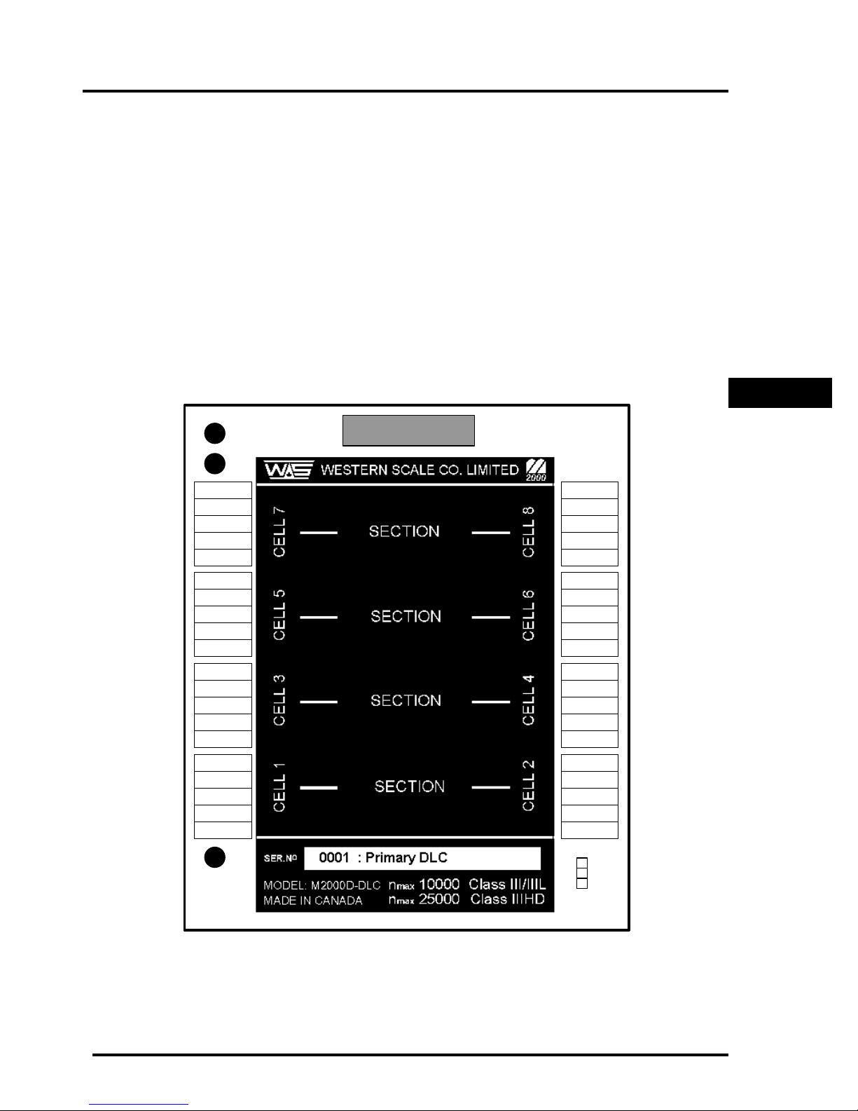
The slaves are labeled as outlined in Figure 2. If the DLC board is set to be a secondary
slave, then the load cell channel numbering will be assigned as (S)econdary 1-8, and
(P)rimary 1-8 if the slave was configured for the primary slave. As outlined in Figure 2,
the analog to digital converter terminals are refered to as cells. Each cell will represent a
corner as part of a scale allocation. The allocation process of a scale that involves
multiple load cells are automatically assigned to unallocated cell terminals. The user does
not have to manually select and allocate cells for a scale setup.
Page 4
Page 10
m2000D technical manual
ID
The following restrictions apply to allocating cells for hopper or sectional scales:
q Hopper Scales
Hopper scale corners can be grouped on a single DLC, they cannot be spread across
two DLC terminal boxes. Hopper scales can be grouped from any of the cells on a
particular DLC slave terminal box.
q Sectional Scales
A scale that uses sections will function in such a way that sections must be paired
together, across from each other as outlined in Figure 2. Two DLCs may be used for a
sectional scale allocation. Sections are allowed to span across DLC slaves. For
instance, the user might apply all 16 cells as a sectional scale which will provide 4
sections on the Primary DLC and 4 sections on the Secondary DLC, etc.
INTRODUCTION
+SIG
- SIG
SHLD
+EXC
- EXC
+SIG
- SIG
SHLD
+EXC
- EXC
+SIG
- SIG
SHLD
+EXC
- EXC
+SIG
- SIG
SHLD
+EXC
- EXC
LINK
TX
DIGITAL LINK
- EXC
+EXC
SHLD
- SIG
+SIG
- EXC
+EXC
SHLD
- SIG
+SIG
- EXC
+EXC
SHLD
- SIG
+SIG
- EXC
+EXC
SHLD
- SIG
+SIG
STATUS
Figure 2: Remote DLC slave Corner & Section grouping
PRM
SEC
SELECT
Page 5
Page 11
m2000D technical manual
Œ
•
Ž
SCALE SETUP USER INTERFACE
The indicator is calibrated using the numeric keypad. There are no potentiometers or
switches to set. The M2000D consists, like its analog counterpart, of 3 scale channels. To
enter calibration mode, type in the scale channel number 19, 29 or 39.
The following keys are assigned special function modes during calibration. The [ON/OFF]
key does not allow power down during calibration. This key is used to select the type of
information to be displayed as outlined below.
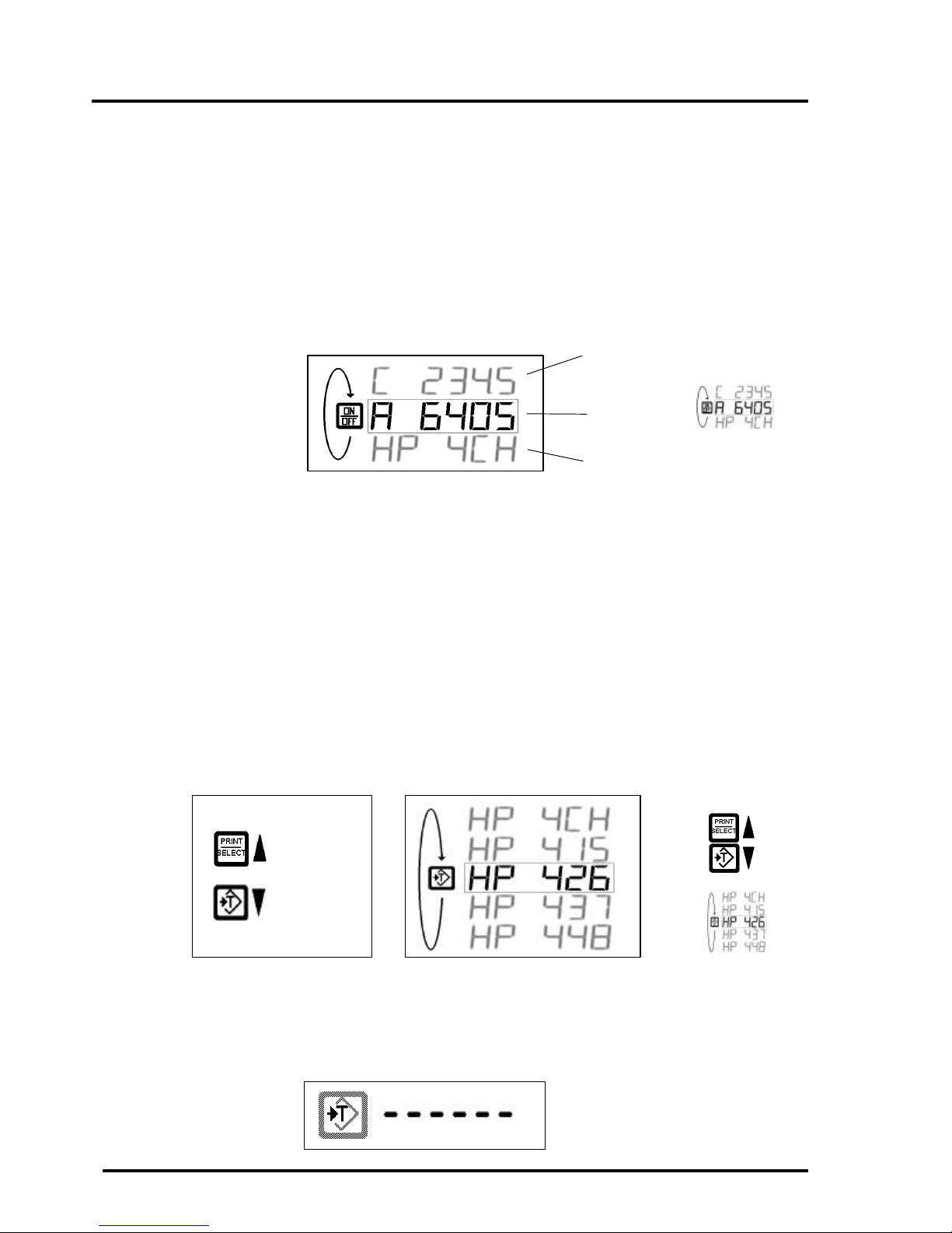
The [ON/OFF] key is used to select between graduated counts Œ, raw counts • (currently
displayed) or status information Ž. The status information shows the user what type of
scale was allocated, how many load cells are involved and to which terminal block they are
assigned. The status information window also shows the current load cell that is selected as
part of the calibration process.
The tare key is also assigned a special function and is used to select the current corner or
section. Most allocation calibration commands pertain to the currently selected load cell as
selected using the [TARE] key. As an example - assume a 4-corner hopper scale assigned
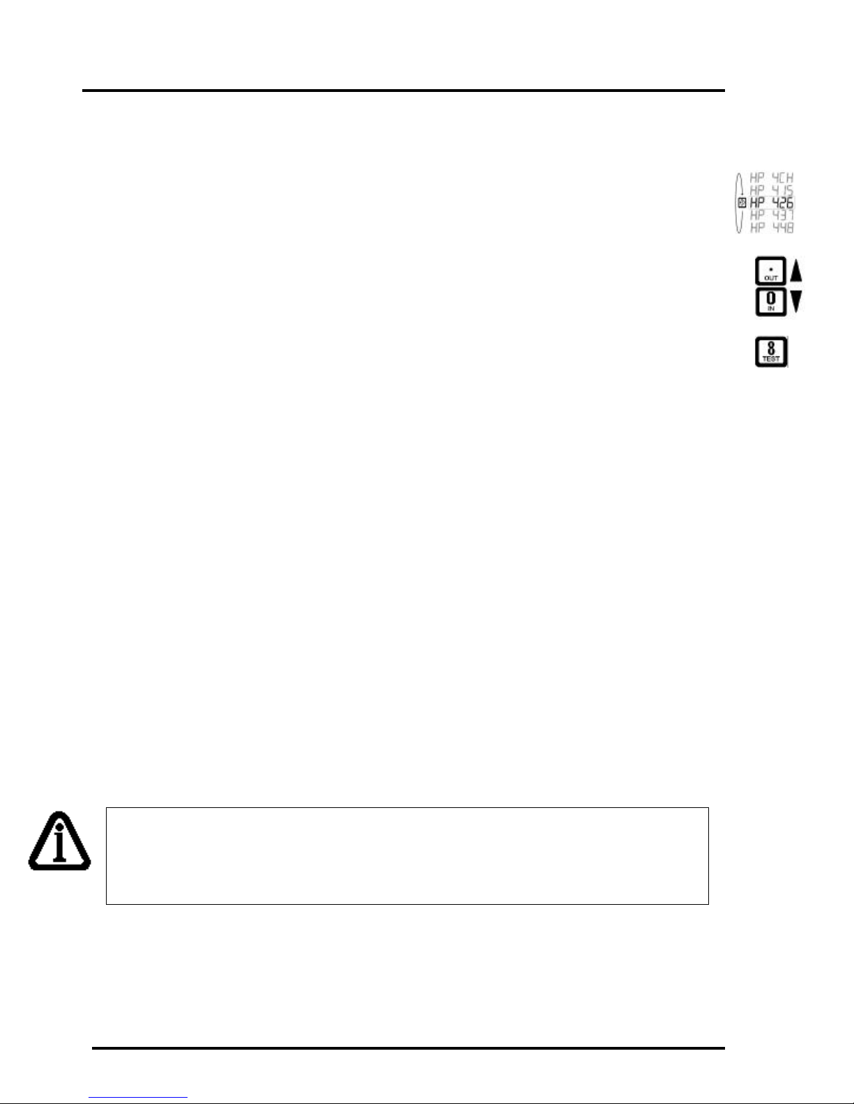
on the primary DLC as shown below. Using the [TARE] key, we can scroll and check one
corner at a time and also the sum total of the individual corners in terms of raw counts or
graduated counts:
SCROLL
UP
SCROLL
DOWN
If no load cells were allocated to a particular scale, or if an invalid scale allocation exists,
the following window will be displayed on the LED display:
Page 6
Page 12
m2000D technical manual
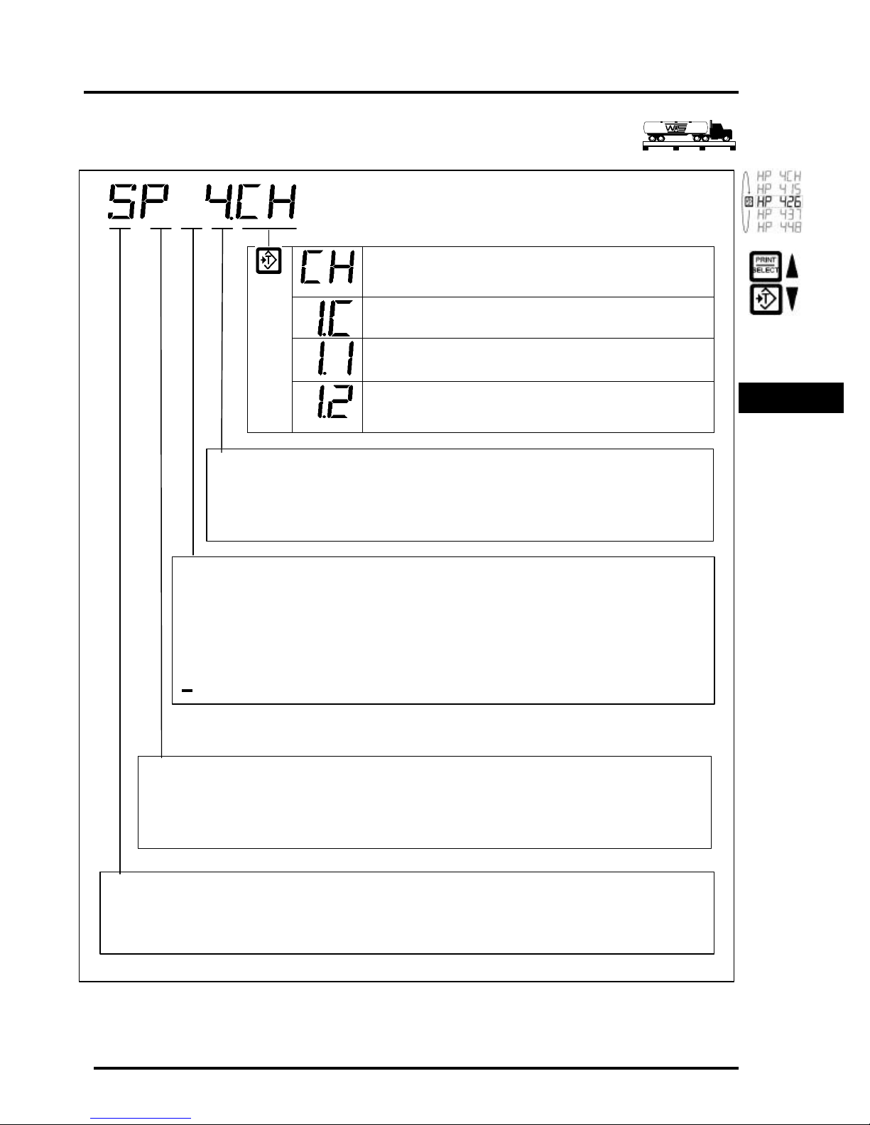
Table 1: Scale Status Information (Sectional Scales)
S – (S)ectional scale allocation
P – (P)rimary DLC slave selected
Number of Sections allocated to the scale
to a single cell on a DLC terminal box.
Channel Status Information
SECTIONAL SCALES
SECTIONAL SCALE - This scale allocation is a 4 Channel
scale consisting of 4 sections starting on the Primary DLC – Press the
[TARE] key to start scrolling through the sections
This is the Combination of the section 1 (in this case section 1 of 4 )
– Press the [TARE ] key to look at the first corner of the section
The first corner of section 1 goes to cell 1 on the Primary DLC terminal
box – Press the [TARE ] key to look at the second corner of the section
The second corner of section 1 goes to cell 2 on the Primary DLC
terminal box – Press the [TARE ] key to move on to the next section
This number indicates the number of sections allocated to the sectional scale.
In this case, the scale consists of 4 sections. Each section represents 2 load cells
referred to as corners. A section consists of two corners where each corner, equates
E - Faulty corner/cell . Only the faulty corner will have a flashing ‘E’ in its status field.
This way the user can scroll through the corners/sections to find out which corners are
diagnosed as faulty. Use the TARE key to scroll through the corners.
D - Corner/cell disabled
A - Corner / Section Adjustment mode activated.
- Cell allocated to another scale – or not accessible to the user
Indicator to show that the section scale is located on the primary DLC
S – (S)econdary DLC slave selected
Indicator to show that the section on this sectional scale is located on the secondary DLC
INTRODUCTION
Indicator to show that a Sectional scale was allocated for this scale channel
H – (H)opper scale allocation
Indicator to show that a Hopper scale was allocated for this scale channel
Page 7
Page 13
m2000D technical manual
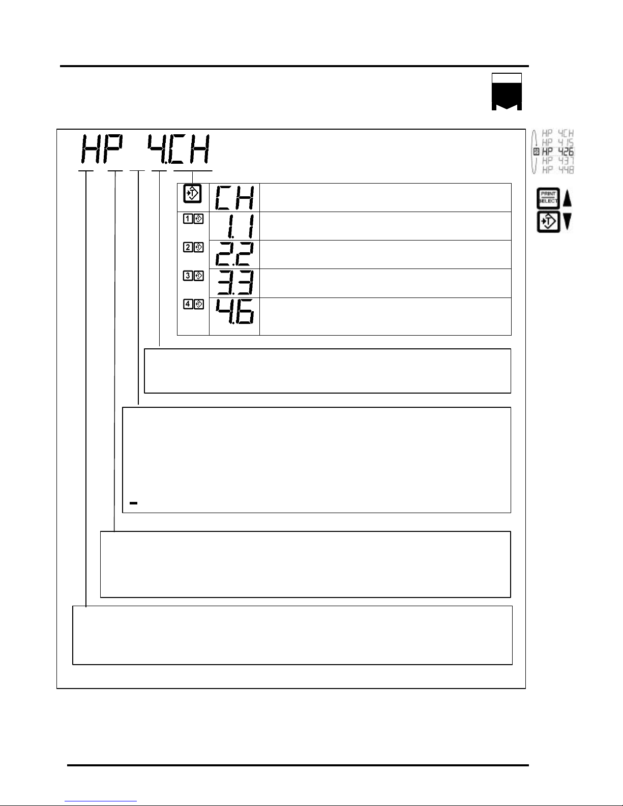
Table 2: Scale Status Information (Hopper Scales)
H – (H)opper scale allocation
P – (P)rimary DLC slave selected
Number of Corners allocated to the scale(1-8)
Channel Status Information
HOPPER SCALES
HOPPER SCALE - This scale allocation is a 4 Channel
Hopper scale consisting of 4 corners on the Primary DLC
corner 1 goes to cell 1 on the Primary DLC terminal box – Press the
[TARE ] key to move to the next corner
corner 2 goes to cell 2 on the Primary DLC terminal box box – Press the
[TARE ] key to move to the next corner
corner 3 goes to cell 3 on the Primary DLC terminal box box – Press the
[TARE ] key to move to the next corner
corner 4 goes to cell 6 on the Primary DLC terminal box
(In this example – cell 4 and 5 were disabled by the user due to damaged
cells using calibration command 525)
This number indicates the number of corners allocated to the hopper scale. A corner
equates to a single cell on a DLC terminal box.
E - Faulty corner/cell . Only the faulty corner will have a flashing ‘E’ in its status field.
This way the user can scroll through the corners to find out which corners are
diagnosed as faulty. Use the TARE key to scroll through the corners.
D - Corner/cell disabled
A - Corner / Section Adjustment mode activated.
- Cell allocated to another scale – or not accessible to the user
Indicator to show that the corners for this hopper scale are located on the primary DLC
S – (S)econdary DLC slave selected
Indicator to show that the corners for this hopper scale are located on the secondary DLC
Indicator to show that a Hopper scale was allocated for this scale channel
S – (S)ectional scale allocation
Indicator to show that a Sectional scale was allocated for this scale channel
Page 8
Page 14

m2000D technical manual
GENERAL INSTALLATION GUIDE
INTRODUCTION AND OVERVIEW
The following information provides a general guide to a successful installation. Please
review these instructions before installing your unit.
High voltages may exist inside the enclosure. To prevent the risk of electrical shock, please
unplug the indicator when opening the enclosure. Installation and servicing of the M2000D
system should be performed only by qualified service personnel.
Complete the wiring of the external devices before connecting the indicator. Wiring should
comply with local area electrical codes. Wherever possible cables should be in conduit or
be otherwise protected from physical damage. Devices mounted outside should be
mounted in suitable enclosures away from direct sunlight. Once the external wiring is
completed, connect the indicator to the remote devices. Use the strain relief fittings
provided to route the cables in the indicator.
GENERAL
INSTALLATION
POWER SUPPLY CONNECTION
The M2000D indicator requires a regulated input with an external source of 10-35 VDC. A
120VAC to 12 VDC adapter is supplied with the indicator. Please pay close attention to
polarity of the power cord. It is important to note that in very noisy industrial
environments, power-conditioning filters would be a requirement to ensure a fail-safe
operation under all conditions. Indicators should not share AC power with electrical
motors and switchgear. Consult with the site engineer for clean AC power.
q Line filters and surge protection for minor static environments
q Constant voltage transformer for typical industrial installations
q UPS protection for highly unstable power sources
In cases where the M2000D unit might be installed in a vehicle or truck, it is important to
provide for power conditioning between the vehicle’s power plant and the indicator. Please
consult with your factory representative for more detail.
NOTE: The M2000D do not include an [ON/OFF] switch. The [ON/OFF] key does
not connect /disconnect the line voltage. The key “ awakens ” the M2000D from a
“sleep” mode.
Page 9
Page 15

m2000D technical manual
LOAD CELL CONNECTION
The main characteristic of a digital system is to prevent long analog load cell cable
connections between the load cell and the indicator. The installation strategy for a digital
system is to have the DLC junction box mounted as close as possible to the weighing
platform, to keep load cell cable runs between load cells and the DLC junction box as short
as possible, to eliminate contamination of load cell analog signals by RFI and EMI
interference.
Because the DLC junction box will be in close approximation to the load cells, losses in
load cell cabling will be kept to a minimum, and so the need for SENSE lines is
eliminated. For this reason, the DLC junction box do not include sense line terminals for
load cells. The load cell interface only requires EXCITATION and SIGNAL lines for a
total of 4 wires. Connecting a 6 conductor load cell cable to a DLC terminal recommends
the +SENSE and +EXCITATION conductors to be joined together and the –SENSE and –
EXCITATION conductors to be joined together respectively.
SERIAL PORT CONNECTIONS
Serial ports can be configured in the normal RS232 modes and to RS485 or RS422 multi
drop modes. Before connecting to the serial port, consideration should be given to the
communications protocol and to any remote requirements to prevent damaging serial ports.
The recommended cable to be used with serial communication is 20 to 28 AWG with a
braided or foil shield. The maximum recommended cable length is 15 meters or 50 feet.
However much longer connections are possible if using a properly shielded, lowcapacitance cable. The shield on a serial cable should only be connected to the M2000D
indicators shield terminal for the serial port in question. Do not connect the shield on both
ends of the cable – one end should be floating (not connected).
DLC COMMUNICATIONS CABLE CONNECTIONS
The DLC communications cable is the heart of the M2000D system. This cable conveys
high-speed digital packetized data between DLC slaves and the M2000D indicator. This
data is error corrected and although some packets might be rejected, the overall system
provides a zero loss data path over a maximum of a 1000 feet of cable. The DLC digital
cable provides optical isolation between the indicator and each of the remote DLC slaves.
The cable should have 4 conductors, one pair for power delivery and one pair for data
communications. The cable should provide a separate foil shield for each pair plus a drain
wire to be connected to the M2000D shield terminal. Do not connect the shield on the
other end of the cable to anything. The recommended cable to be used is type 22 AWG
(0.32 sq. mm), with each pair of conductors foil shielded.
Page 10
Page 16
m2000D technical manual
Œ•Ž•‘’“
•
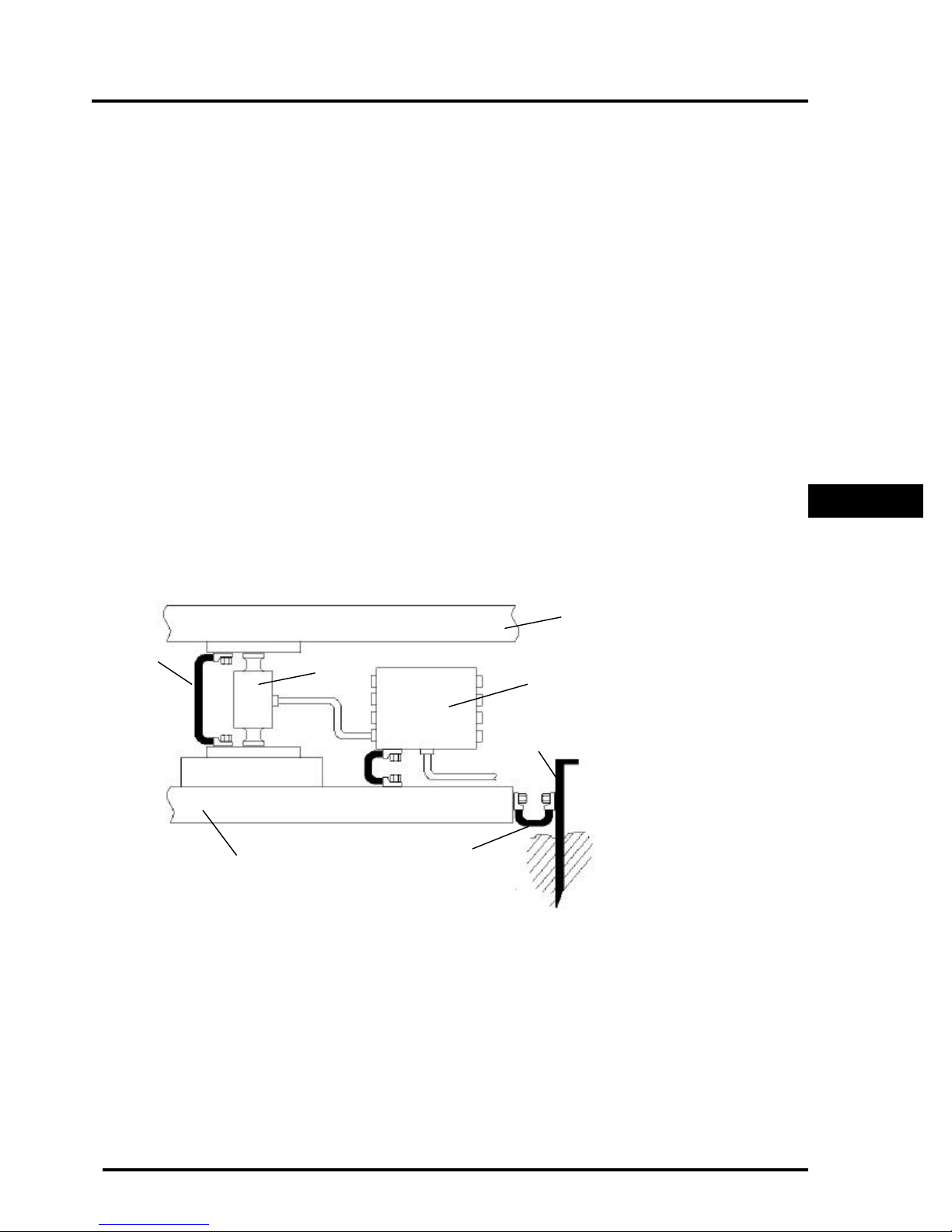
SYSTEM GROUNDING
The following information deals with grounding as it relates to lightning and electrostatic
discharges to earth ground. The M2000D provides for surge protection, however in order
for surge conditions to be diverted properly, a good earth ground path should be in place.
Surge protection components by themselves will not absorb all electrostatic discharge – it
should simply divert charges safely to an earth ground path. Because the indicator is
galvanically isolated from the remote DLC slaves, both ends should be grounded to a good
earth connection.
Normally the DLC terminal box will be mounted onto the steel chassis of the weigh
platform with a braided earth strap to the steel structure of the weighing platform. The steel
frame should be connected to a metal rod planted in the earth close by the weighing
platform. Earth straps should be at least 8 AWG thick and preferably no longer than 2 feet.
The earth strap should be kept as straight as possible - kinks in the earth straps induce
inductive resistances to the discharge path to earth ground.
GENERAL
INSTALLATION
Earth Strap
Œ
Load Cell
•
Platform Chassis
Ž
Earth Strap
•
DLC Junction Box
•
Weigh Platform
‘
Earthing Rod
’
Earth Strap
“
Page 11
Page 17

m2000D technical manual
(Intentionally Left Blank)
Page 12
Page 18
m2000D technical manual
SECTIONAL SCALE INSTALLATION GUIDE
Sectional scale installations do allow sections across multiple DLC slaves. The following
set of instructions is a general guideline on how to allocate and calibrate sectional scales:
1. Install load cell cables to DLC slave units starting from the lowest cell number on the primary
slave as labeled on the DLC boxes. Numbering should be incremental from one end of the
platform to the other end.
2. Once all load cells are connected, choose the scale to which you would like to allocate the
sectional scale, using commands 19, 29 or 39 to enter the calibration mode for the setup
procedure.
3. Note, if this is a new installation, normally the first command in calibration mode before
allocating the load cells, is to clear all existing allocations using calibration command 500, else
use commands 501,502 or 503 respectively
4. You are now ready to execute the sectional scale allocation command 521. This command
requires you to enter the number of sections you would like to assign to the scale (a section
consists of two load cells referred to as corners) as outlined in Figure 2.
5. Once command 521 is executed, you can view the raw counts of the scale on a section by
section basis. Use the [ON/OFF] key to select raw counts, and then use the [TARE] key to
move incrementally from one section/corner to another. This is an initial test to see if all load
cells are responding.
6. Note, if this is a new installation, command 530 needs to be executed to clear any existing
corner correction factors that might be resident in the remote DLC slave – very important.
7. At this point (as an optional step), the user can use command 11 to set the desired AD range
value for all the converters associated with the scale, to optimize the resolution of the AD
converters. Each AD converter can produce 512 000 raw counts at full AD input range.
8. Press the [ON/OFF] key until you see graduated counts (prefixed by the letter C). Graduated
counts always represent the sum of all the corners/cells.
9. The scale is now ready to be dead loaded using command 12 (this might take about 3 to 5
seconds). Do not disturb the platform(s) while the process is in progress. If the graduated
counts do not display zero counts, repeat the process.
10. The scale is now ready to be spanned using command 13. Place a graduated weight of ±1/3 of
the scale capacity in the center of the scale (if practical) and execute command 13 to span the
scale.
11. You are now ready to do section/corner corrections where needed, moving a graduated weight
from the center of one section to another or to a corner of a section. Press the [ON/OFF] key
until you see graduated counts (prefixed by the letter C). Use the [TARE] key to select the
summed display of a section or a corner (post fixed with the letter C on the display) of interest.
12. Once the section/corner is selected, use command 532/531 (default 532) to adjust the
section/corner weight to the expected weight - if required. When using command 532 you must
type in a target weight - command 532 will automatically adjust the section/corner to the target
weight. When using command 531, you must use the [IN/OUT] keys to increase or decrease
the weight. Command 532 is normally the first method used to correct sections/corners. If the
results are not satisfactory, command 531 can be used for a final correction. If required, the
user may correct on a corner by corner basis.
13. Press the [ON/OFF] key until graduated counts are displayed (prefixed by the letter C).
14. If the results are not satisfactory, move back to step 10 and repeat.
SECTION SCALE
INSTALLATIONS
NOTE: Saving calibration data on a regular basis using calibration command 99 is a
good calibration practice.
Page 13
Page 19
m2000D technical manual
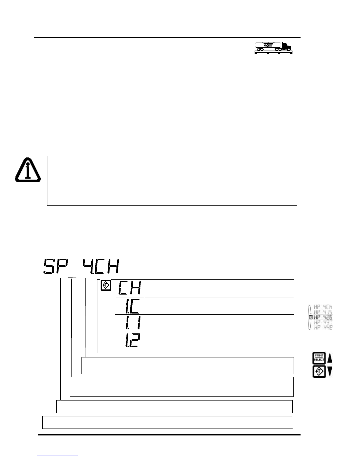
The sectional scale assigned consists of a total of 4 sections. This parameter indicates
the number of sections assigned to the sectional scale.
Status information : Please consult the general status info table for a detailed list of
521 Assign a Sectional Scale: calibration command
This command allocates the number of sections specified as the parameter to allocate a
sectional scale for the current scale under calibration (a section consists of 2 corners –
each corner gets assigned to a cell on the DLC box). For example, if a 4 sectional scale
is required, 4 will be entered at the keypad.
It is the task of the indicator to find the number of sections to assign for a sectional scale.
Sections will always be assigned incrementally starting from the first section on the
primary DLC slave 1/2, 3/4, 5/6, 7/8 through to the secondary slave etc., as required. If the
user does not want a section to be assigned (due to damage of the cell in question) the
user should first disable the cells using calibration command 525 before assigning the
scale
NOTE: If the system could not find any allocation space on either the primary or secondary DLC, it
will return with an error message. If this is a new system and this is the first scale assignment, it is
recommended to first perform a command 500 to clear all existing scale allocation information (all scale
information will be lost). If the allocation was unsuccessful and other scales do exist that need to stay
active, use Commands 501, 502 or 503 to clear only the current scale allocation information. Keep in
mind that the M2000D indicator has 3 scales.
The following examples illustrate how to interpret the assignment information displayed
on the LED display while in calibration mode for a sectional scale. Use the [ON/OFF] key
to select the status display window. Taking the example of a sectional scale with 4 sections
– the status information provides the following allocation information. It displays how
many sections were assigned to this scale, and to which terminals each corner of each
section is assigned to. The status information is displayed as follows:
scale consisting of 4 sections starting on the rimary DLC – Press the
This is the C
– Press the [TARE first corner of the section
– Press the [ ] key to look at the second corner
The second corner of section 1 cell 2 on the rimary DLC terminal
Press the [TARE ] key to move on to the next section
- This scale allocation is a 4 annel
1 goes to on the P DLC terminal box
possible status information indicators.
The section scale starts on the Primary DLC box and might expand to the secondary DLC.
This is a sectional scale allocation S =(S)ECTIONAL
Page 14
Page 20
m2000D technical manual
Œ • Ž •
Œ • Ž •
1 2 3 4 5 6 7 8
1 2 3 4 5 6 7 8
SECTIONAL EXAMPLE (1)
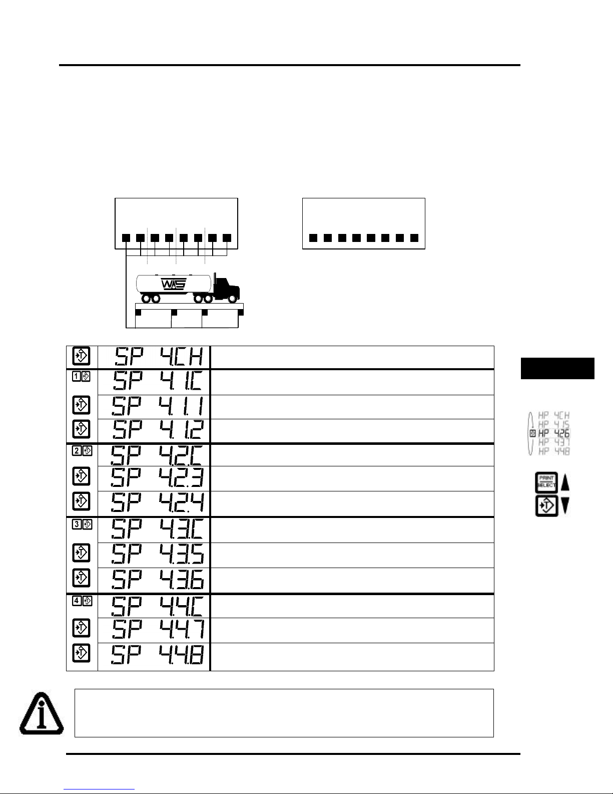
Once the 4-section scale is allocated, the allocation information pertaining to each section
of the sectional scale can be viewed by pressing the [TARE] key to scroll through all the
sections and related corners. At any time we can look at the raw counts of a corner or
section using the [ON/OFF] key. When viewing the status information window on the
LED display, using the [ON/OFF] key, we can see the related status information as
follows:
DLC (P)RIMARY DLC (S)ECONDARY
SECTIONAL SCALE - The allocation information indicates that we are
looking at the sum of all 4 sections of a sectional scale starting on the Primary DLC
ΠSection as the C
The first corner of section 1 cell 1 on the rimary DLC terminal box
1 goes to on the P DLC terminal box
• 2 as the ombination of the two associated corners
The first corner of section goes to cell 3 Primary
The second corner of section 2 cell 4 on the rimary DLC terminal box
Section 3 Combination of the two associated corners
3 goes to on the P DLC terminal box
The second corner of section 3 goes to cell 6 on the Primary DLC terminal box
• Section 4 as the Combination of the two associated corners
The first corner of section 4 goes to cell 7 on the Primary DLC terminal box
SECTION SCALE
INSTALLATIONS
NOTE: At any time the user can press the [ON/OFF] key to view the raw counts
related to the corner in question.
The second corner of section 4 goes to cell 8 on the Primary DLC terminal box
Page 15
Page 21
m2000D technical manual
Œ • Ž •
• ‘
Œ • Ž •
• ‘
Œ
•
Ž
•
•
‘
Œ
•
Ž
•
•
‘
1 2 3 4 5 6 7 8
1 2 3 4 5 6 7 8
SECTIONAL EXAMPLE (2)
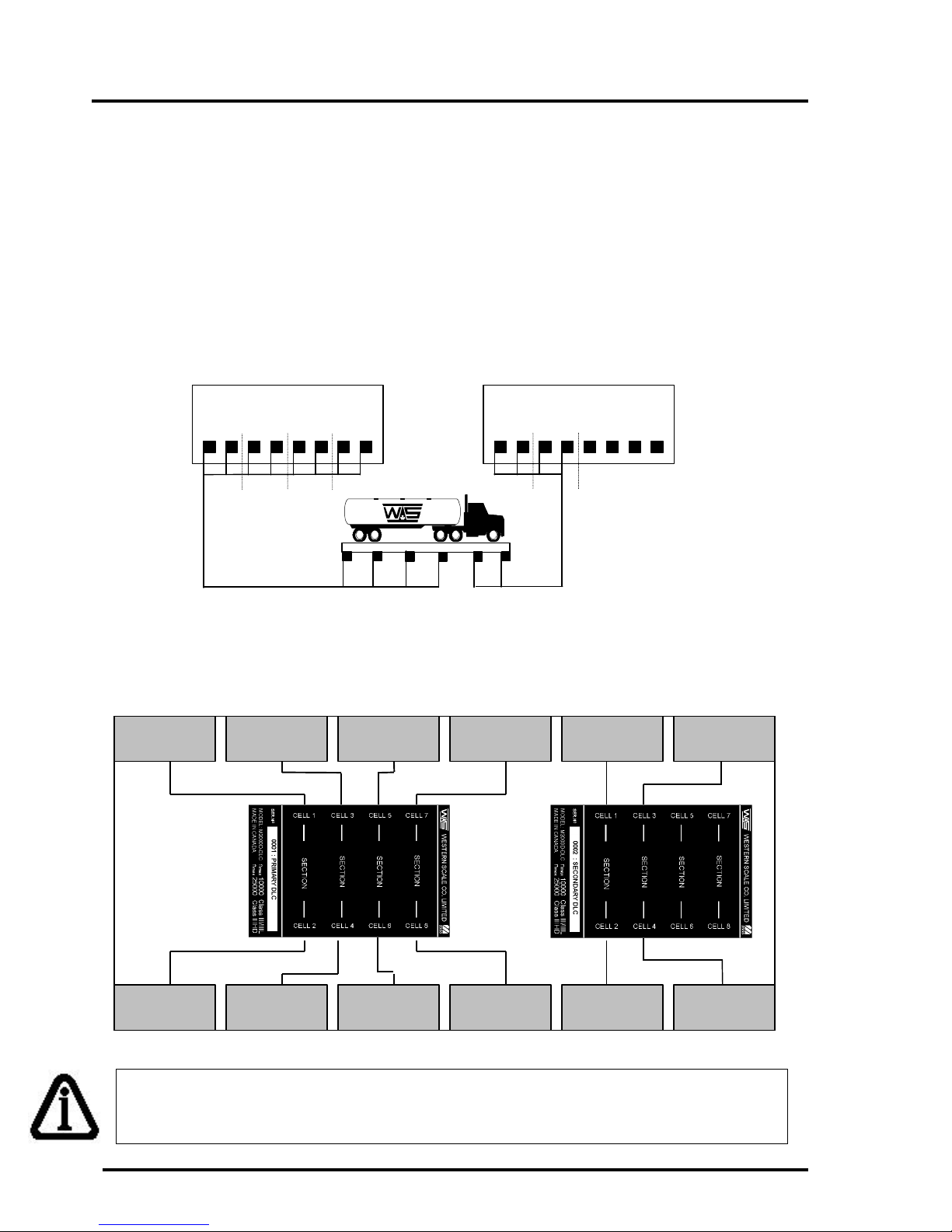
The next example of a sectional scale allocation illustrates the allocation of sections across
two DLC slaves, which is valid for sectional scales. We assume the following setup
scenario:
q We have two 8 channel DLC slaves for a total of 16 cells
q We have both Primary and Secondary DLC units connected to the M2000D
q We require a sectional scale with 6 sections ( total of 12 load cells)
DLC (P)RIMARY DLC (S)ECONDARY
The diagram below outlines the connection diagram of the 6 sectional scale, starting with
section Πon the Primary DLC terminal box and ending on the Secondary DLC.
Section
Section
Section
Section
Section
Section
Section
Section
Section
Section
Section
Section
NOTE: At any time the user can press the [ON/OFF] key to view the raw counts
related to the corner in question.
Page 16
Page 22
m2000D technical manual
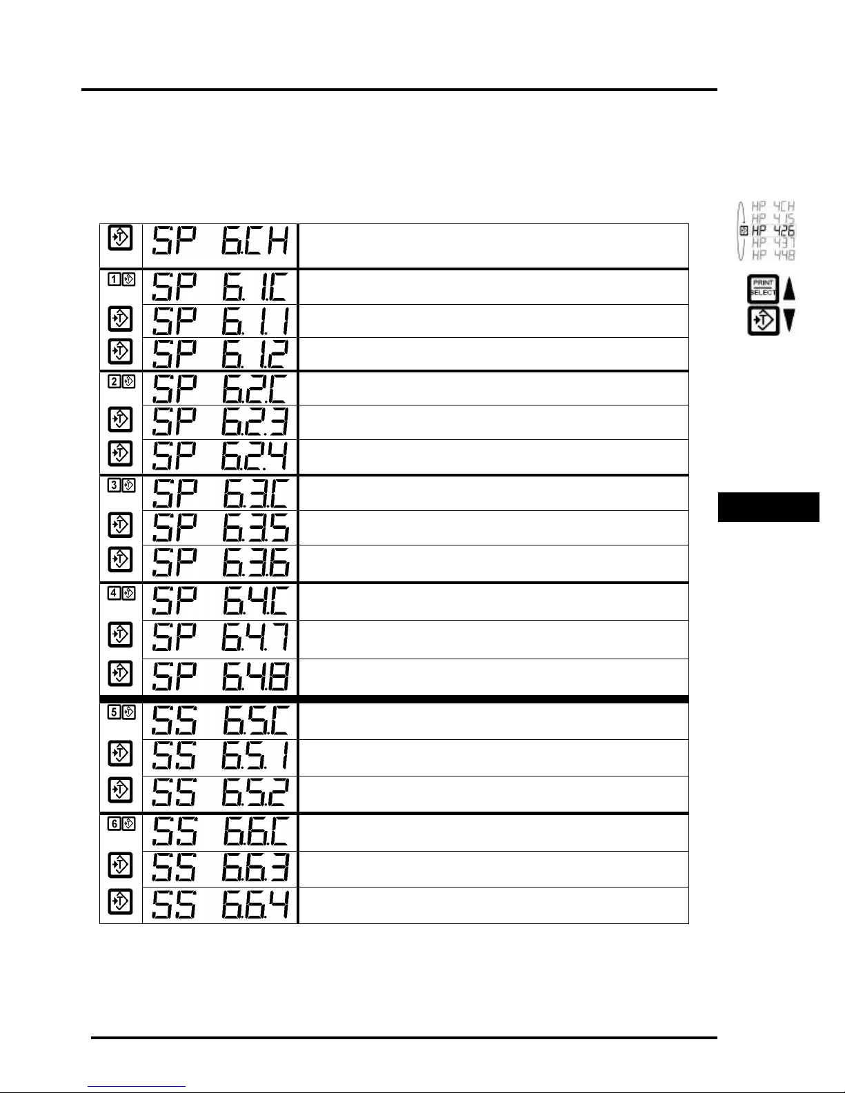
Once we have allocated the sectional scale using command 521, we can use the [TARE]
key in calibration mode to scroll through all the sections and related corners and use the
[ON/OFF] key to observe the raw counts as required. The table below outlines and
explains the status information as we scroll through the sections and corners using the
[TARE] key.
SECTIONAL SCALE - The allocation information indicates that we are
looking at the sum of all 6 sections of a sectional scale starting on the Primary DLC
ΠSection 1 as the Combination of the two associated corners/cells
The first corner of section 1 goes to cell 1 on the Primary DLC terminal box
The second corner of section 1 goes to cell 2 on the Primary DLC terminal box
• Section 2 as the Combination of the two associated corners /cells
The first corner of section 2 goes to cell 3 on the Primary DLC terminal box
The second corner of section 2 goes to cell 4 on the Primary DLC terminal box
Ž Section 3 as the Combination of the two associated corners/cells
The first corner of section 3 goes to cell 5 on the Primary DLC terminal box
The second corner of section 3 goes to cell 6 on the Primary DLC terminal box
• Section 4 as the Combination of the two associated corners/cells
The first corner of section 4 goes to cell 7 on the Primary DLC terminal box
The second corner of section 4 goes to cell 8 on the Primary DLC terminal box
• Section 5 as the Combination of the two associated corners/cells
The first corner of section 5 goes to cell 1 on the Secondary DLC terminal box
The second corner of section 5 goes to cell 2 on the Secondary DLC terminal box
‘ Section 6 as the Combination of the two associated corners/cells
The first corner of section 6 goes to cell 3 on the Secondary DLC terminal box
SECTION SCALE
INSTALLATIONS
The second corner of section 6 goes to cell 4 on the Secondary DLC terminal box
Page 17
Page 23

m2000D technical manual
(Intentionally Left Blank)
Page 18
Page 24
m2000D technical manual
HOPPER SCALE INSTALLATION GUIDE
The following set of instructions is a general guideline on how to allocate and calibrate a
hopper scale with no more than 4 load cells per hopper scaled.
1. Install load cell cables to DLC slave unit starting from cell 1 as labeled on the DLC slave. The
first corner is always assigned to the cell with the lowest number.
2. Once all load cells are connected, choose the scale to which you would like to allocate the
hopper scale, using commands 19, 29 or 39 to enter the calibration mode for the setup
procedure.
3. Note, if this is a new installation, normally the first command in calibration mode before
allocating the load cells, is to clear all existing allocations using calibration command 500.
4. You are now ready to execute the hopper scale allocation command 520. This command
requires you to enter the number of corners you would like to assign to the scale.
5. Once command 520 is executed, you can view the raw counts of the scale on a corner by
corner basis first, using the [ON/OFF] key to select raw counts, and then using the [TARE] key
to move incrementally from one corner to another – each corner is assigned to a cell on the
DLC terminal box. This is an initial test to see if all load cells are responding.
6. Note, if this is a new installation, command 530 needs to be executed to clear any existing
corner correction factors that might be resident in the remote DLC slave – very important.
7. At this point (as an optional step), the user can use command 11 to set the desired AD range
value for all the cells/corners associated with the scale, to optimize the resolution of the AD
converters. Each cell can produce 512 000 raw counts at full input range.
8. Press the [ON/OFF] key until you see graduated counts (prefixed by the letter C). Graduated
counts always represent the sum of all the corners/cells.
9. The scale is now ready to be dead loaded using command 12 (this might take about 3 to 5
seconds). Do not disturb the platform while the process is in progress. If the graduated counts
do not display zero counts, repeat the process.
10. The scale is now ready to be spanned using command 13. Place a graduated weight of ±1/3 of
the scale capacity in the center of the scale and execute command 13 to span the scale.
11. You are now ready to do corner/cell corrections where needed, moving a graduated weight
from one corner to another. Use the [TARE] key to select the corner of interest. Once the
corner is selected, use command 532/531 ( default 532) to adjust the corner weight to the
expected weight - if required. When using command 532 you must type in a target weight command 532 will automatically adjust the corner to the target weight. When using command
531, you must use the [IN],[OUT] keys to increase or decrease the weight. Command 532 is
normally the first method used to correct corners. If the results are not satisfactory, command
531 can be used for a final correction.
12. Press the [ON/OFF] key until graduated counts are displayed (prefixed by the letter C).
Graduated counts always represent the sum of all the corners/cells.
13. If the results are not satisfactory, move back to step 10 and repeat
14. Once calibration is finished, you can use command 600 outside calibration mode to inspect the
scale behavior without violating the government certification.
HOPPER SCALE
INSTALLATIONS
NOTE: A hopper scale is not allowed to have load cells spread across multiple DLC
slaves terminal boxes – must be grouped on a single DLC slave . A sectional scale does
not have this limitation. Saving calibration data on a regular basis using calibration
command 99 is a good calibration practice.
Page 19
Page 25
m2000D technical manual
HOPPER SCALE
on the Primary DLC – Press the [TARE] key to start scrolling through the scale corners
The hopper scale allocated consists of a total of 4 corners. This parameter indicates the
number of corners assigned to the hopper scale.
Status information: Please consult the general status info table for a detailed list of possible
status information indicators.
520 Assign a Hopper Scale: calibration command
This command allocates the number of corners typed in as a parameter for a hopper scale
allocation for the current scale under calibration. For example - if a 4-corner hopper scale
is required, 4 will be entered. A corner equates to a single cell on the DLC terminal
box. The M2000D has 3 scales, to enter calibration mode for any one, use commands 19,
29 or 39.
It is the task of the indicator to find the number of cells not disabled or assigned to other
scales. The available cells will then be mapped to the corners. The indicator will scan the
online DLC slaves available and enabled cells starting on the primary DLC and ending on
channel 8 on the secondary DLC.
NOTE: If the system could not find any allocation space on either the primary or
secondary DLC, it will return with an error message. If this is a new system and this is
the first scale assignment, it is recommended to first perform a command 500 to clear
all existing scale allocation information (all scale information will be lost). If the
allocation was unsuccessful and other scales do exist that need to stay active, use
Commands 501, 502 or 503 to clear only the current scale allocation information.
Command 501-503 only clears the current scale under calibration. Keep in mind that
the M2000D indicator has 3 scales.
The following examples illustrate how to interpret the assignment information displayed
on the LED display while in calibration mode for a hopper scale. Taking the example of a
4-corner hopper scale – we will look at the following aspects. First we specified 4 (the
logical) corners as part of the hopper scale. Secondly, we need to know to which of the
cells on the DLC boxes these 4 corners were assigned to (the physical cell terminal
numbers). This information is displayed as follows:
- This scale allocation is a 4 Channel hopper scale consisting of 4 corners
Primary DLC - the corner in question is assigned on the Primary DLC unit
H – (H)opper scale allocation - the user allocated a Hopper type scale
Page 20
Page 26
m2000D technical manual
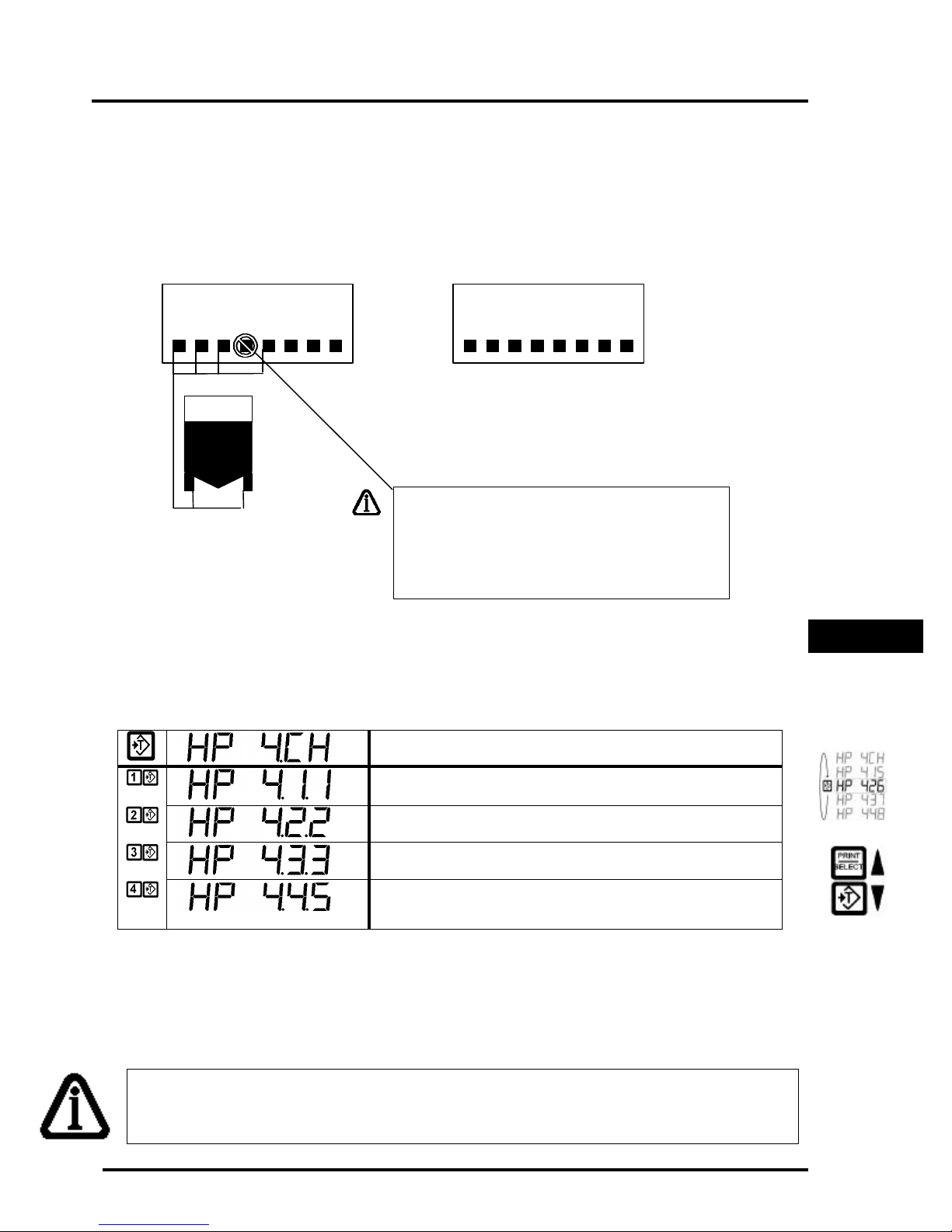
Œ•Ž••
HOPPER EXAMPLE (1)
Once the 4-corner hopper scale is allocated (in calibration mode), the allocation
information pertaining to each corner of the hopper scale can be viewed as follows by
pressing the [TARE] key while in calibration mode:
DLC (P)RIMARY
DLC (S)ECONDARY
NOTE: As illustrated in this example the user
can disable a cell that is damaged. Please see
calibration command 525 on how to disable cells.
Disabling cells should be done before assigning
the scale.
HOPPER SCALE
INSTALLATIONS
HOPPER SCALE - This scale allocation is a 4 Channel Hopper
scale consisting of 4 corners on the Primary DLC
Πcorner 1 goes to cell 1 on the Primary DLC terminal box
• corner 2 goes to cell 2 on the Primary DLC terminal box
NOTE: At any time the user can press the [ON/OFF] key to view the raw counts
related to the corner in question.
Ž corner 3 goes to cell 3 on the Primary DLC terminal box
• corner 4 goes to cell 5 on the Primary DLC terminal box
(In this example cell 4 was disabled due to damage)
Page 21
Page 27
m2000D technical manual
Œ•Ž••‘’“
•‚ƒ„
1 2 3 4 5 6 7 8
1 2 3 4 5 6 7 8
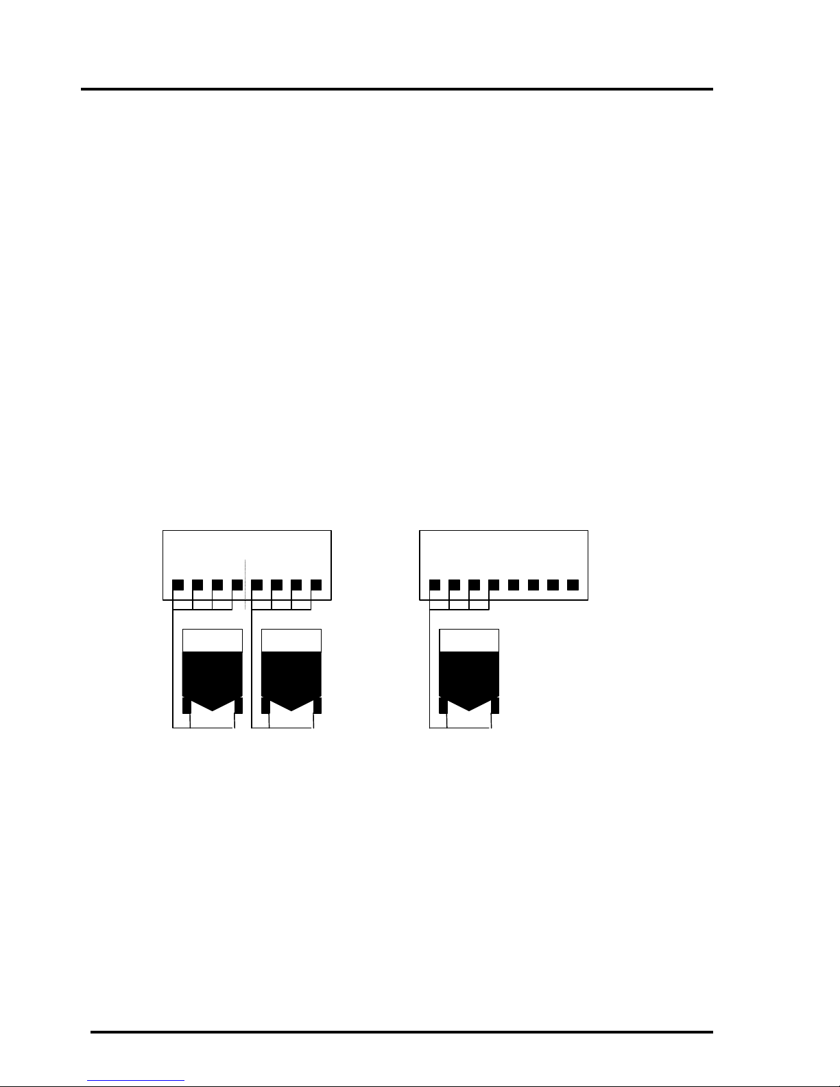
HOPPER EXAMPLE (2)
The next example of hopper scale allocation assumes the following scenario:
q We have two 8 channel DLC slaves for a total of 16 cells
q We have both Primary and Secondary DLC units connected to the indicator
q We require 3 hopper scales of 4 corners each
The M2000D supports 3 scale channels. We must allocate a single hopper scale per scale
channel. First we enter calibration mode for scale 1 by executing command 19, and after
entering a password we allocate the first hopper scale using calibration command 520.
After completing the first scale allocation, we exit calibration mode. The next step is to
allocate hopper scale 2 by entering calibration mode for scale 2, the executing command
29. After entering a password we allocate hopper scale 2 using calibration command 520.
Once we complete the hopper scale installation, we exit calibration mode. The final step is
to enter calibration mode executing command 39 to allocate the third hopper scale. Once
in calibration mode we use calibration command 520 to allocate the third hopper scale.
Once all 3 the hopper scales are allocated based on the above criteria using calibration
command 520, we may observe the following allocation setup information:
DLC (P)RIMARY
SCALE 1 SCALE 2 SCALE 3
DLC (S)ECONDARY
Page 22
Page 28
m2000D technical manual
scale 1
primary
scale 2
primary
scale 3
secondary
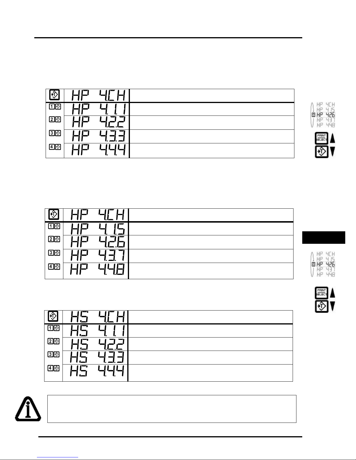
The following information can be viewed by entering calibration mode for each of the 3
scales respectively, and using the [TARE] key to scroll through the status information.
The hopper scale allocation information for
would look as follows:
HOPPER SCALE 1 - The allocation information indicates that we are
looking at the sum of 4 corners of a hopper scale on the primary DLC
Πcorner 1 goes to cell 1 on the Primary DLC terminal box
• corner 2 goes to cell 2 on the Primary DLC terminal box
Ž corner 3 goes to cell 3 on the Primary DLC terminal box
• corner 4 goes to cell 4 on the Primary DLC terminal box
The hopper scale allocation information for
would look as follows:
HOPPER SCALE 2 - The allocation information indicates that we are
looking at the sum of 4 corners of a hopper scale on the primary DLC
• corner 1 goes to cell 5 on the Primary DLC terminal box
‘ corner 2 goes to cell 6 on the Primary DLC terminal box
on the
on the
DLC slave
DLC slave
HOPPER SCALE
INSTALLATIONS
’ corner 3 goes to cell 7 on the Primary DLC terminal box
“ corner 4 goes to cell 8 on the Primary DLC terminal box
The hopper scale allocation information for
on the
DLC slave
would look as follows:
HOPPER SCALE 3 - The allocation information indicates that we are
looking at the sum of 4 corners of a hopper scale on the secondary DLC
• corner 1 goes to cell 1 on the Secondary DLC terminal box
‚ corner 2 goes to cell 2 on the Secondary DLC terminal box
ƒ corner 3 goes to cell 3 on the Secondary DLC terminal box
„ corner 4 goes to cell 4 on the Secondary DLC terminal box
NOTE: At any time the user can press the [ON/OFF] key to view the raw counts
related to the corner in question.
Page 23
Page 29

m2000D technical manual
(Intentionally Left Blank)
Page 24
Page 30
m2000D technical manual
GENERAL ALLOCATION RELATED COMMANDS
500 Clear All Remote DLC scale allocations : calibration command
This command will reset and invalidate any scales allocated to scale channels 1, 2 and 3.
All information will be erased. This command is typically used for a new installation to
clear any existing scale allocations. This command is also recommended as the first
command to be executed during a new, first time configuration.
To perform a remote reset function, press 1 followed by the [TARE] key. The indicator
will clear all scale allocations locally and remotely inside the DLC slaves.
NOTE: All scale calibration data for all 3 scales will be cleared and erased. All data will be lost. This
command is of use typically in new installations where the installation and calibration process needs to
be performed.
A
C
501 Clear Scale 1 Allocation: calibration command
502 Clear Scale 2 Allocation: calibration command
503 Clear Scale 3 Allocation: calibration command
This command will reset and invalidate the current calibrated scale. The M2000D has 3
scales, to enter calibration mode for any one, use commands 19, 29 or 39. All information
will be erased. This command is typically used for a new installation to clear any existing
scale allocations to scale 1.
To perform a remote clear function on scale 1, press 1 followed by the [TARE] key. The
indicator will clear the scale allocated locally and remotely inside the DLC slaves.
GENERAL DLC
COMMANDS
Page 25
Page 31
m2000D technical manual
525 DLC Load Cell Masking: calibration command
The purpose of this command is to disable/enable cell channels to be allocated to a scale.
This is an advanced feature, for normal scale allocations using commands 520/521 this
command would not be necessary. This command is of use where a cell inside a DLC box
is not operational or for a custom setup as required.
Use the [TARE]/[ZERO] or the [IN/OUT] keys to scroll through the available cells in the
DLC system.
Every time the user enters calibration mode, the cell mask table will be cleared to enable
all unallocated cells for possible allocation. It is then up to the user to exclude cells that
should not be part of the scale allocation process, using 520/521 for possible scale
allocation.
The scale allocation commands 520/521 always start looking for available analog
channels, starting at the first cell on the primary DLC slave and ending the search at
the last cell on the secondary slave. If the user would not want a cell to be included
during this scale allocation search, command 525 allows cells to be disabled to be
excluded from a scale allocation.
Use the [PRINT/SELECT] key to toggle between enabled state and disabled state for the
corner in question. If nothing happens when the [PRINT/SELECT] key is pressed, it means
that the corner that is currently selected is in use by another scale channel.
Once all the preferred mask settings are made, press the [CLEAR] key to exit the
command. The mask settings will be cleared once calibration mode is exited. Please
consult the table in Table 1 - scale status information.
This command works closely with scale allocation commands 520 and 521. This command
will display the status information on the LED display.
Page 26
Page 32

m2000D technical manual
530 Reset Corner Field adjustment entries: calibration command
Field adjustment entries are the corner span corrections applied to corners during
calibration, these entries would be cleared for new scale installations. Normally command
530 is performed directly after a scale was allocated using commands 520 or 521.
This command only affects the selected scale under calibration.
This command will reset the field span and zero adjustment entries for the scale in
question.
In scales containing multiple load cells it is often required to do small corrections to
selected load cells in order to make the scale’s response consistent for any weight
placement. Commands 532/531 are used to make these small corrections to the corner/cell
selected by the user using the [TARE] key. If the user is not satisfied with the current span
adjustment values, command 530 can be used to clear the correction values and the user
can then repeat the adjustment process using commands 532/531 if required.
GENERAL DLC
COMMANDS
Page 27
Page 33
m2000D technical manual
Channel Status Information
531 Corner / Section Manual Span Adjustment: calibration command
This command allows the field personnel to adjust for small linearity discrepancies on a
corner or section basis for a hopper or sectional scales.
This command will act on the currently selected corner or section as outlined in the
status display. Before executing this command, use the [TARE] key to select the corner /
section to be adjusted for span corrections. Place a reference weight on the corner/section
to be adjusted.
Execute command 531 followed by [PRINT/SELECT], the display will flash the currently
selected corner/section to be adjusted – press [PRINT/SELECT] to confirm the corner to
be adjusted or [CLEAR] to abort the command.
The adjustment mode is now activated. The correction can be viewed in real time, use the
[ON/OFF] key to view either scale-graduated counts (default) or the raw counts related to
the corner under correction. The following keys are assigned special functions while in
adjustment mode:
q Use the [IN] key to increase the weight of the corner or section
q Use the [OUT] key to decrease the weight of the corner or section
q Use keys 1, 2, 3 and 4 to select the coarseness of the correction increments, where 4 is
very coarse and 1 very small increments (default to 4)
q Use the [CLEAR] or [PRINT/SELECT] or [TARE] key to exit corner / section
adjustment mode
q Use the [ON/OFF] key to toggle between display modes, raw counts, graduation counts
or status display as shown in the example below
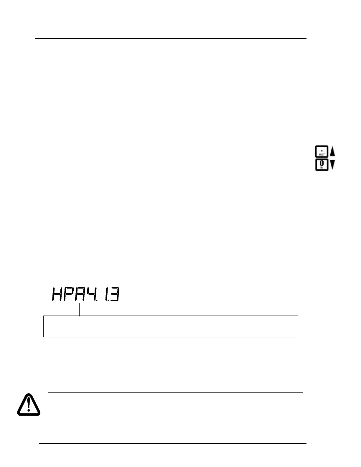
A – This field will flash while in Corner / Section Adjustment mode
While in corner or section adjustment mode, the allocation information will indicate that
we are correcting a corner or section. While in corner/section adjustment mode, switching
to a new corner or section will not have any effect. Use [CLEAR] or [PRINT/SELECT] to
exit corner correction mode.
The new correction values will only be saved to permanent storage once calibration
mode is exited.
Page 28
Page 34
m2000D technical manual
Channel Status Information
532 Auto Corner Span Adjustment: calibration command
This command allows the field personnel to adjust for small linearity discrepancies on a
corner or section basis for a hopper or sectional scales. This command serves the same
purpose as command 531 but instead of adjusting weight in a manual way, we simply type
in the weight and the system will automatically span the selected corner/section to the
target weight.
This command will act on the currently selected corner or section as outlined in the status
display. The instructions below outline the steps for corner/section adjustments:
q Before executing this command, use the [TARE] key to select the corner / section to be
adjusted for span corrections.
q Use the [ON/OFF] key to display graduated weight counts before executing the
command – display prefixed with a flashing letter ‘C’.
q Place a reference weight on the corner/section to be adjusted.
q Execute command 532 followed by [PRINT/SELECT], the display will flash the
currently selected corner/section to be adjusted – press [PRINT/SELECT] again to
confirm the corner to be adjusted or [CLEAR] to abort the command.
q Enter the value of the weight currently on the scale (gross) followed by pressing the
[TARE] key. Once the user pressed [TARE] the adjustment to the target weight will
take place. This command remembers the last weight entered, so the user can just press
the [TARE] key in stead of repeatedly having to enter the weight value.
If you are not happy with the correction you can clear it using command 530, please see
command 530 for details. Command 530 clears all correction entries for all section and
corners.
While the adjustment is in progress the following information will be displayed as shown
in the example below:
A – This field will flash while in Corner / Section Adjustment mode
GENERAL DLC
COMMANDS
Page 29
Page 35

m2000D technical manual
551 DLC communications Error Counter: Calibration command
This command is accessible from within or outside calibration mode.
This command displays the number of aborted packets on the DLC communications line in
real time. If this error count seems to increase abnormally high over a short period of time,
it may indicate a noisy communications path or a general communications hardware
failure.
552 DLC Packet Counter: Calibration command
This command is accessible from within or outside calibration mode.
This command displays the number of successful transmitted packets on the DLC
communications line. This command keeps track of the number of packets received in real
time. The throughput of the system can be measured by sampling this counter over 1
minute. Dividing the packet counter by 60 will yield the number of packets received per
second.
In the case of only one scale being allocated, the through put of the system will simply be
the samples per second as calculated above. With two scales attached to the system, the
throughput of the system will be the packets per second divided by 2. In the case where
there are 3 scales allocated to the system, the throughput will be the packets per second
divided by 3.
Page 30
Page 36

m2000D technical manual
555 DLC Software Upgrade Download: calibration command
This command prepares the indicator for a software upgrade to one of the remote DLC
slave units. The software is downloaded via the M2000D indicator to one of the DLC slave
units using the M2000 download software. For a DLC slave to be upgraded, it must be
registered with the system – use command 620 to register slaves or to check their online
status.
The download sequence takes place over COM1 of the M2000D indicator and
communicates with a PC, using the M2000 download software supplied by the factory.
Upgrading the firmware of a DLC remote unit should in most cases not influence the
calibration information and scale allocation settings.
The DLC to be upgraded should be specified by supplying a parameter to indicate which
DLC unit to upgrade.
q 1 – Primary DLC
q 2 – Secondary DLC
After entering the parameter the command should be completed by pressing 1, followed by
the [TARE] key.
556 Obtain DLC BIOS Firmware version information: calibration command
This command will require a parameter to obtain the firmware version of the DLC in
question:
q 1 – Primary DLC
q 2 – Secondary DLC
557 Obtain DLC BOOT Firmware version information: calibration
This command will require a parameter to obtain the firmware version of the DLC in
question:
q 1 – Primary DLC
q 2 – Secondary DLC
GENERAL DLC
COMMANDS
Page 31
Page 37
m2000D technical manual
558 DLC Set AD Range For Active Corner: calibration command
This command is similar to calibration command 11 but has some distinctions.
Command 558 will change the currently displayed corner/section or scale as a whole,
depending on which corner the user scrolled to in calibration mode. Use the [TARE] key to
scroll to the corner in question while in calibration mode – please see the table on scale
status information for more detail.
When entering command 558, it will return with the current setting of the corner/section. If
the value displayed on the screen is zero, it implies that the AD range settings for the
individual corners in a section are not the same.
NOTE: Changing the AD range will require a mandatory dead load and span
The input range values are as follows:
q 0 Indicate AD range not the same for the grouping of corners
q 1 for 0 to +/- 9mV
q 2 for 0 to +/- 19mV
q 3 for 0 to +/- 39mV (default)
q 4 for 0 to +/- 79mV
Page 32
Page 38

m2000D technical manual
592 Restore System Setup From DLC slave: calibration command
This command is a calibration command. It will restore a previous backup from any one of
the two DLC slaves to the master indicator. This command goes hand in hand with
calibration command 591 – used to backup the system data. This process will overwrite
any existing setup information with that provided by the backup stored in the DLC slave.
The information affected is the calibration information and the action tables. For this
command to work correctly, the correct number of DLC slaves should be connected to the
network in order to facilitate a correct system configuration. This command is of use in the
following scenarios:
q After a typical calibration session, it is recommended to back up the calibration and
action table information, for possible disaster recovery scenarios.
q It might be useful to provide a user with a pre-configured DLC in the field, in order to
speed up the installation process.
q The user would like to revert to a backup due to a setup failure or corruption of system
data during installation or maintenance.
This command requires a parameter to specify the slave from which the backup should be
obtained, as follows:
q 1 – restore system data from Primary Slave
q 2 – restore system data from Secondary Slave
To exit this command press the [CLEAR] key.
GENERAL DLC
COMMANDS
Page 33
Page 39
m2000D technical manual
591 Backup System Setup To a DLC slave: calibration command
This command is a calibration command. This command will back up the current system
setup to any one of the two DLC slaves from the master indicator. This command goes
hand in hand with calibration command 592.
It is important to note that the backup will be generated from the last saved calibration
and action table information as stored in the M2000D indicator. The user should first
exit calibration mode to make sure that the information is saved to backup memory.
The user should then enter calibration mode and issue command 591 to backup to one
of the DLC slaves in question.
The information included in the backup image of the system data is the calibration
information and the action tables. This command is of use in the following scenarios:
q After a typical calibration session, it is recommended to back up the calibration and
action table information, for possible disaster recovery scenarios.
q It might be useful to provide a user with a pre-configured DLC in the field in order to
speed up the installation process, by just issuing a restore command to configure the
system.
q The user would like to revert to a backup due to a setup failure or corruption of system
data during installation or maintenance.
To exit this command press the [CLEAR] key.
594 Reload Scale Allocation: calibration command
This command is a calibration command. This command is typically used for field DLC
replacements. This command can be used to download the latest scale allocation to a DLC.
This is handy when performing a field replacement of a DLC unit. This command will
download the original setup to the new DLC. This command assumes that a valid
calibration and scale allocation is available to be downloaded to the new DLC. Once down
loaded the user can save the settings by exiting calibration mode -command (99).
All DLCs are factory calibrated to give the same counts per millivolt input for all DLC
cells. This allows the user to replace a faulty DLC in the field without having to
recalibrate the scale. The user simply install the new DLC and in calibration mode
execute command 594 to download the previously stored calibration data to the new
DLC. Exiting calibration mode (99) will save the calibration data in the new DLC
slave.
Page 34
Page 40
m2000D technical manual
576 Query Active DLC Cells on Slaves: calibration command
This command is a calibration command. This command provides a means of first
obtaining the current active cells per DLC slave, and secondly providing the option of
changing the number of active AD converters per slave. If the user does not know the
number of active cells per slave, the user may simply count the number of installed load
cell connectors on the DLC slave. Enter this number as a parameter to set the number of
active converters for the DLC slave in question.
The command first requires the user to enter the slave to be queried. Please enter one of the
following values:
q 1 - Query the primary slave for active cells
q 2 - Query the secondary slave for active cells
The indicator will return number from the slave in the range from 1-8 representing the
number of active cells on that slave. The user may enter a new AD converter number
between 1-8 followed by [PRINT/SELECT] or simply press the [CLEAR] key to exit the
command. Only the factory is allowed to make permanent changes to this setting – the
user may only look at the setting.
The factory can supply 3 variations of DLC slaves
q 4 channel DLC slave
q 6 channel DLC slave
q 8 channel DLC slave
Every time the user allocates a scale, the indicator will query the slave for its active
AD converter number in order to know how many load cells to make available to the
user for a scale allocation. When using calibration command 525 in conjunction with
commands 520 and 521, command 525 will prevent the user from selecting
corners/sections outside the boundaries as reflected by command 576. For instance, if
command 576 returns an active number of 4, then corners 5,6,7 and 8 will not be made
available to the user for a scale allocation. Also, if command 576 returns an active
number of 6 corners, then corners 7 and 8 will not be made available to the user for a
scale allocation, and so on.
GENERAL DLC
COMMANDS
Page 35
Page 41
m2000D technical manual
600 Scale Status/Diagnostics Information: non-calibration command
This command displays the status information pertaining to the currently selected scale.
This is a non-calibration command executed outside of calibration mode.
First select the scale for which status information is desired from, by using 1, 2 or 3
followed by [PRINT/SELECT].
This command has the following important information:
q The primary purpose of this command is to show what type of scale was allocated to
the scale in question.
q The user can scroll through all the corners and sections to obtain status information on
each corner using the [IN]/[OUT] keys. Please consult the table on Scale Status
Information for more details on how to interpret this status information.
q The command allows us to look at each of the corner’s error timeout counters by
pressing the [TEST] key.
q The command allows the user to look at each of the corner’s raw counts in real time by
pressing the [TEST] key.
After entering the command, use the [IN/OUT] keys to scroll through the allocation
information pertaining to the scale in question. If at any point the user wishes to look at the
error timeout counter or raw counts of a particular corner, just press the [TEST] key once.
Pressing the [TEST] key will toggle the display between the timeout display and the raw
counts display until the user presses the [CLEAR] key. The error counter should under
normal operating conditions stay at zero, if this number fluctuates heavily it is an
indication of a possible hardware problem.
To exit the error counter information, press [CLEAR] key once. To exit this command,
press the [CLEAR] key once more.
The user can scan through all corners/sections of the system to check the error status
field for each corner/cell of the DLC. A flashing “E” in the status screen for a
particular cell will indicate a fault condition related to the cell. The user can then
inspect the raw counts of the cell and do a physical inspection on the load cell in
question.
Page 36
Page 42
m2000D technical manual
620 DLC Slave Line Status: non-calibration command
This command can be executed in or outside of calibration mode. This command will
indicate to the user how many slaves were found to be online. The results can be
interpreted as follows:
q 0 – no slaves found to be online
q 1 – only Primary slave found
q 2 – only Secondary slave found
q 3 – both Primary and Secondary slaves found
TIP: If both slaves are configured for the same slave ID, no slaves will be detected. If
the user has only one DLC installed, it should be configured as the primary slave. If
the user has two DLC slaves installed, the slave with the largest number of cells should
be configured as the primary slave.
GENERAL DLC
COMMANDS
Page 37
Page 43

m2000D technical manual
(Intentionally Left Blank)
Page 38
Page 44
m2000D technical manual
3.3V Li
BATTERY
DLC LINK
Œ•Ž
Œ•Ž••
Œ•Ž••
Œ•Ž••
•
GENERAL CABLE CONNECTION GUIDE
M2000D INDICATOR CONNECTIONS
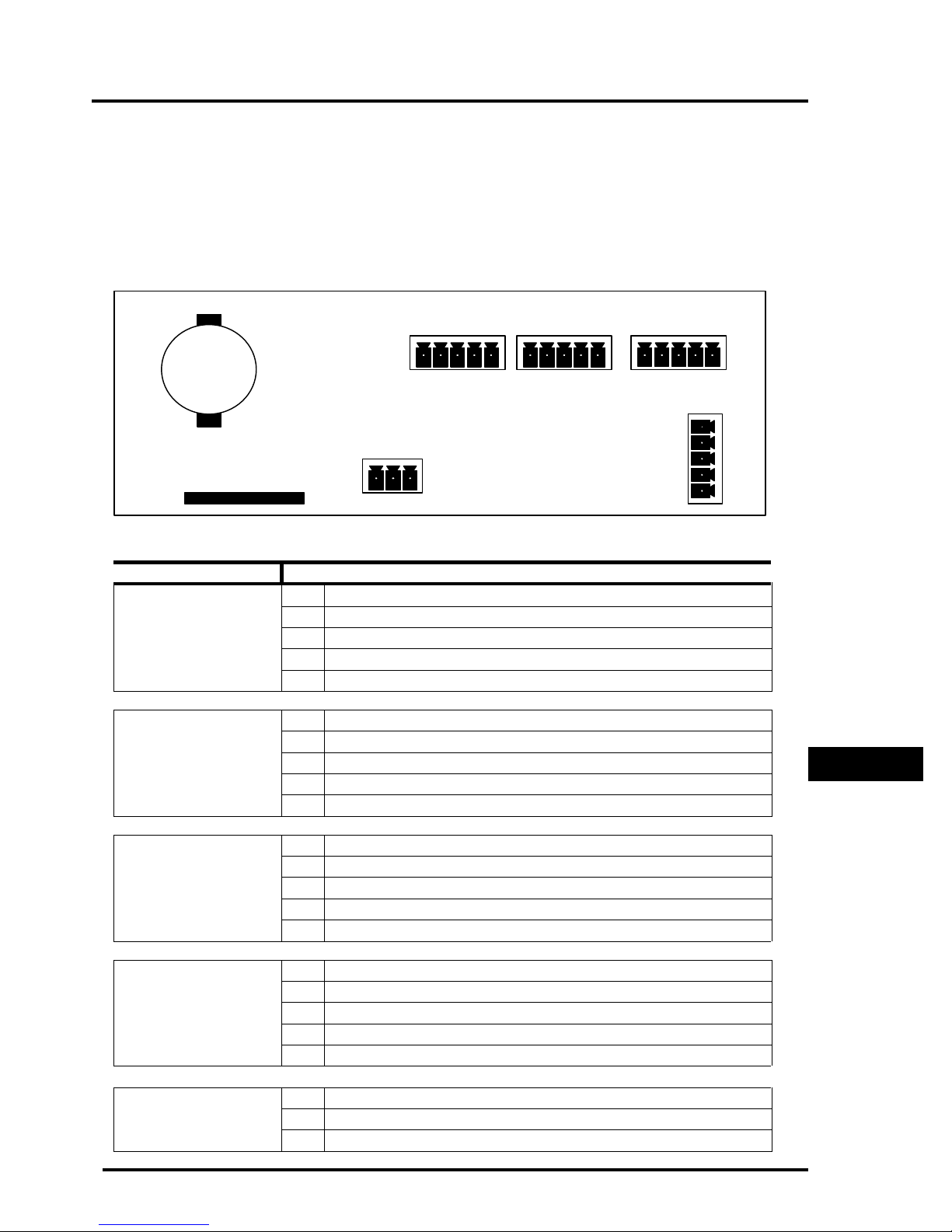
The diagram below is a general outline of the connectors as seen on the back of the circuit
board for the M2000D indicator:
COM2
POWER
KEY PAD
M2000D Indicator External Connections
CONNECTOR PIN DESCRIPTION
DLC LINK (SCALE)
COM 1
CTL - (DLC network cable)
•
CTL + (DLC network cable)
•
SHL (Ground)
Ž
V - (DLC slave power supply)
•
V + (DLC slave power supply)
Œ
CTS (Input –Printer telling the Indicator to send more data RTS)
Œ
RX (Input – data received by the Indicator)
•
TX (Output – data transmitted by the Indicator)
Ž
RTS (Output – Indicator signal readiness to receive data
•
COM (Ground)
•
COM1
SMARTWIRE
•
Ž
•
Œ
GENERAL CABLE
CONNECTIONS
COM 2
Œ
•
Ž
•
•
SMART WIRE
Œ
•
Ž
•
•
POWER
Œ
•
Ž
CTS (Input –Printer telling the Indicator to send more data RTS)
RX (Input – data received by the Indicator)
TX (Output – data transmitted by the Indicator)
RTS (Output – Indicator signal readiness to receive data
COM (Ground)
NC (No connection)
B (RS485 differential signal)
A (RS485 differential signal)
V+ (SMARTWIRE Power supply)
V- (SMARTWIRE Power supply)
V- (negative )
GND (earth ground)
V+ (positive power)
Page 39
Page 45
m2000D technical manual
Œ
Œ
Œ
Œ
•
•
•
•
Œ
DLC CONNECTIONS
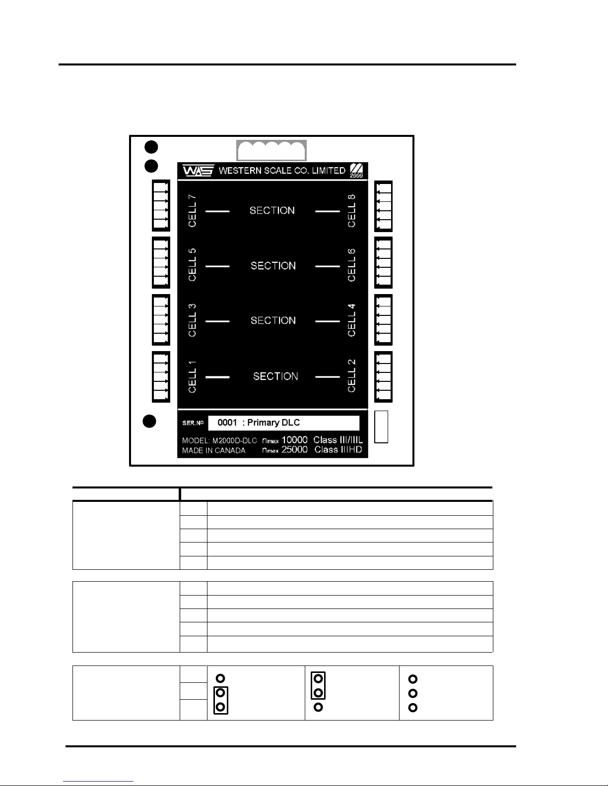
The diagram below is a general outline of the connectors as seen on the remote DLC
terminal boxes:
LINK
TX
•
•
Ž
•
•
•
Ž
•
•
•
Ž
•
•
•
Ž
•
STATUS
DIGITAL LINK
Œ
•
Ž
•
Œ
•
Ž
•
Œ
•
Ž
•
Œ
•
Ž
•
•
Ž
ID SELECT
DLC External Connections
CONNECTOR PIN DESCRIPTION
CELL 1-8
DIGITAL LINK
ID SELECT
(JUMPER SELECT)
EXC - ( 0VDC excitation voltage for load cells)
Œ
EXC+ (+5VDC excitation voltage for load cells)
•
SHL (Ground)
Ž
SIG - ( - Load cell signal )
•
SIG+ (+ Load cell signal)
•
V+ (DLC Power supply)
Œ
V- (DLC Power supply)
•
Spare terminal
Ž
+ CTL (Current loop network input)
•
•
- CTL (Current loop network output)
Œ
SECONDARY DLC
•
SLAVE
PRIMARY DLC
SLAVE
Ž
Page 40
MAINTENANCE
MODE
Page 46
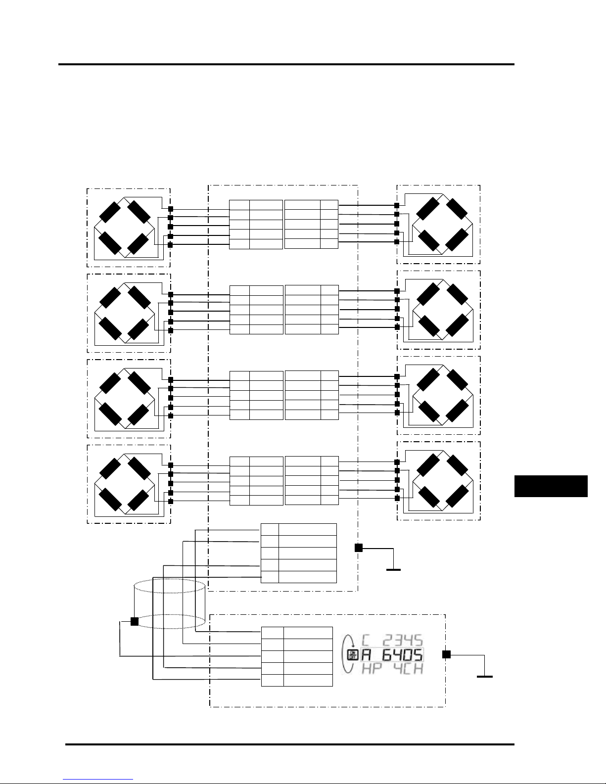
m2000D technical manual
SINGLE DLC SLAVE CONNECTION
The diagram below demonstrates a typical wiring diagram of load cells to the slave DLC
and the DLC slave to the M2000D indicator:
DLC SLAVE
CORNER2 CORNER1
1 - EXC
2 +EXC
3 SHLD
4 - SIG
5 +SIG
CORNER4 CORNER3
1 - EXC
2 +EXC
3 SHLD
4 - SIG
5 +SIG
- EXC 1
+EXC 2
SHLD 3
- SIG 4
+SIG 5
- EXC 1
+EXC 2
SHLD 3
- SIG 4
+SIG 5
CORNER6 CORNER5
1 - EXC
2 +EXC
3 SHLD
4 - SIG
5 +SIG
CORNER8 CORNER7
1 - EXC
2 +EXC
3 SHLD
4 - SIG
5 +SIG
- EXC 1
+EXC 2
SHLD 3
- SIG 4
+SIG 5
- EXC 1
+EXC 2
SHLD 3
- SIG 4
+SIG 5
DLC LINK
1 CTL2 CTL+
3
4 V5 V+
M2000D INDICATOR
DLC LINK
5 CTL4
3 SHL
2 V1 V+
GENERAL CABLE
CONNECTIONS
CTL+
Page 41
Page 47
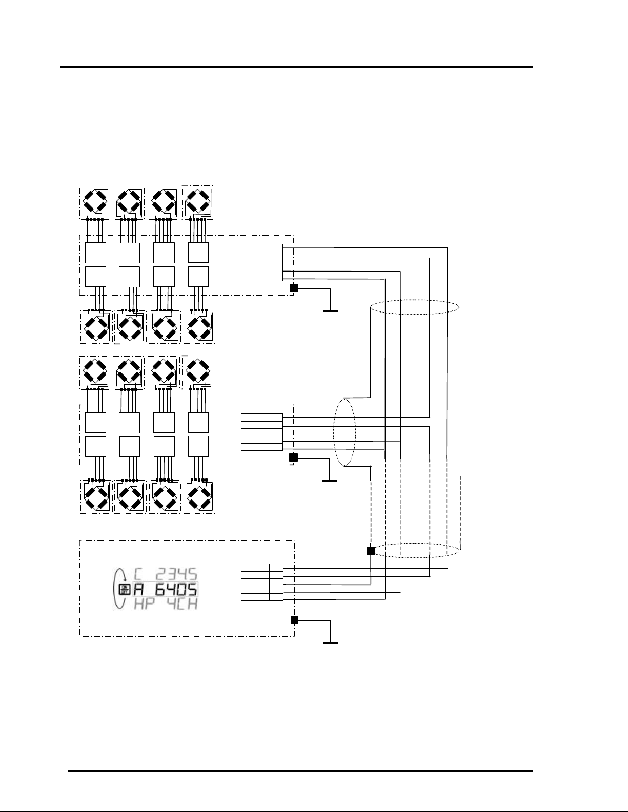
m2000D technical manual
DUAL DLC SLAVE CONNECTION – TYPE 1
The diagram below demonstrates a wiring diagram for instances where the two DLC slaves
are grouped close to one another but far from the indicator. Please pay attention to the
current loop cable configuration when connecting two DLC slaves:
DLC SLAVE
CL- 1
CL+ 2
3
V- 4
V+ 5
DLC SLAVE
CL- 1
CL+ 2
3
V- 4
V+ 5
M2000D INDICATOR
CTL- 5
CTL+ 4
SHLD 3
V- 2
V+ 1
Page 42
Page 48
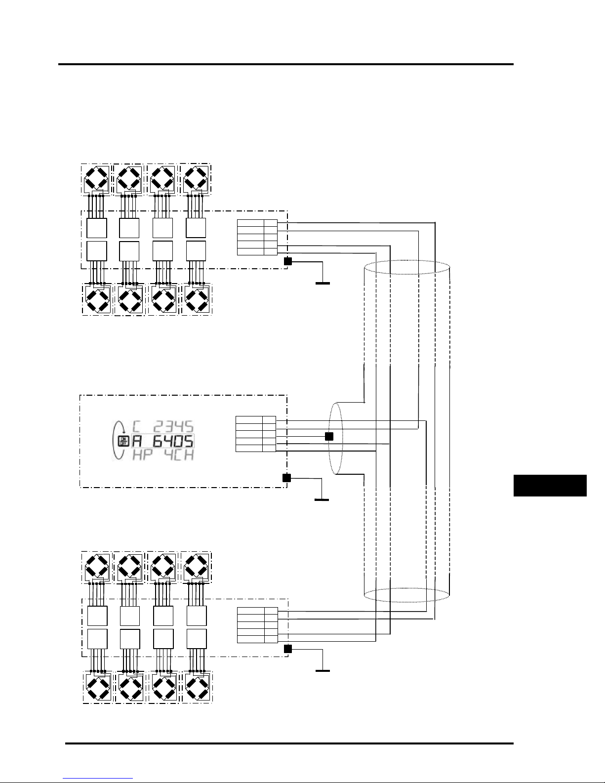
m2000D technical manual
DUAL DLC SLAVE CONNECTION – TYPE 2
The diagram below demonstrates an alternative wiring diagram for instances where the two
DLC slaves are far removed from each other. Please pay attention to the current loop cable
configuration when connecting two DLC slaves:
DLC SLAVE
CL- 1
CL+ 2
3
V- 4
V+ 5
M2000D INDICATOR
CL- 5
CL+ 4
SHLD 3
V- 2
V+ 1
DLC SLAVE
CL- 1
CL+ 2
3
V- 4
V+ 5
GENERAL CABLE
CONNECTIONS
Page 43
Page 49
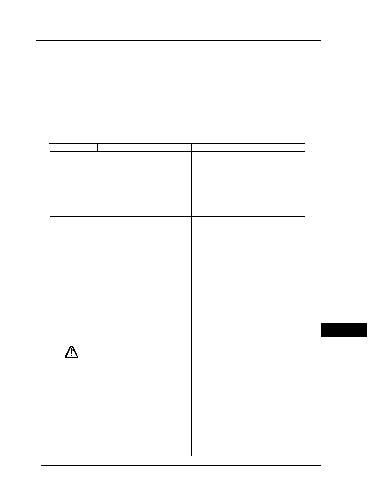
m2000D technical manual
GENERAL DIAGNOSTICS
DLC STATUS INDICATORS
The following information describes the use of the 3 status LEDs located on the DLC slave
boards as a means of making a meaningful diagnosis of the state of the DLC
communications link.
DLC - STATUS LED
LED STATE INTERPRETATION REMEDY
Œ
Blinking
consistently
once every
second
•
Blinking
consistently
10 times a
second
Ž
Blinking one
short
followed by
one long
consistently
DLC slave is configured to operate as
the primary slave in normal run mode.
CONDITION – normal
DLC slave is configured to operate as
the secondary slave in normal run
mode CONDITION – normal
DLC slave is in firmware upgrade
mode and configured as the primary
slave. CONDITION – abnormal
OPTIONAL: To operate the DLC as secondary
slave, change the slave ID jumper to the
secondary position. This jumper is located on
the DLC slave board.
Changing the slave ID jumper should only
be done in calibration mode. The jumper
setting gets stored with the calibration data.
This state is entered when the user removed the
ID select jumper from the DLC slave before
power up. This state is used in conjunction with
calibration command 555 to update the
firmware in the DLC slave.
•
Blinking two
short
followed by
one long
consistently
•
Non of the
above
sequences
DLC slave is in firmware upgrade
mode and configured as the secondary
slave. CONDITION – abnormal
CONDITION - abnormal
This mode might also be entered automatically
during bootup if the DLC slave detects an
invalid code image of the firmware.
If this mode was entered intentionally, proceed
with firmware upgrading. Else, power down
and up again to alleviate the condition. If
condition persists, perform a firmware upgrade.
When two DLC slaves are connected, one DLC
should be in state Πand the other slave in
state • Slaves should never be in the same
state, which will cause communication failures.
In such a case, make sure that the ID select
jumpers on the slaves are not set to the same
position.
Changing the slave ID jumper should only
be done in calibration mode. The jumper
setting gets stored with the calibration data.
GENERAL
DIAGNOSTICS
Page 44
Page 50
m2000D technical manual
DLC – LINK LED
LED STATE INTERPRETATION REMEDY
Œ
PermanentlyonIndicates that network communications
link is valid.
•
Ž
Flickering
but mostly
on
Non of the
above
Indicates that network commands are
send to the slaves.
CONDITION - abnormal If the LINK LED does not light up at all, a
If the LINK LED does not light up at all, a
communications error exist. Check DLC
communications cabling. Consult the section on
general wiring diagrams for proper connection
of communications lines.
Normal while in calibration mode, however
outside calibration mode it should be in state Œ
communications error exist. Check DLC
communications cabling. Consult the section on
general wiring diagrams for proper connection
of communications lines.
Page 45
Page 51

m2000D technical manual
DLC – TX LED
LED STATE INTERPRETATION REMEDY
Œ
PermanentlyonIndicates that slave in question is
responding to commands send by the
indicator and is valid - normal
•
Flickering
but mostly
on
Indicates that network commands are
send to the slaves - normal
If the TX led does not light up at all, diagnosis
might be one of the following:
• The DLC slave has no corners assigned to
any scale by the indicator – this is not an
error condition
• If the user intended to allocate corners on
the slave in question and the TX LED does
not light up, slave has a serious operating
error. Try to clear all scale allocations and
re-assign the scale allocations using
commands 501,502,503 or 500.
NOTE: Command 500 erases all calibration
data for all three scales.
Normal while in calibration mode, however
outside calibration mode it should be in state
Πif the DLC has corners assigned to a
particular scale.
Ž
Permanently
off
Indicates that the indicator does not
require any runtime data from the slave
outside calibration mode - normal
If the DLC in question does not contribute to
any scale allocations, the TX led on the slave in
question should be permanently off, outside
calibration mode.
Normal while in calibration mode, however
outside calibration mode it should be in state
Πif the DLC has corners assigned to a
particular scale.
If the DLC in question does not contribute to
any scale allocations, the TX led on the slave in
question should be permanently off, outside
calibration mode.
GENERAL
DIAGNOSTICS
Page 46
Page 52

m2000D technical manual
Error Messages
1 Invalid parameter number for calibration mode
2 Graduation size invalid
3 Decimal Position Invalid
4 Flag values must be 1 for ‘ON’ and 0 for ‘OFF’
5 Push to Zero Window must be 0-99
6 Zero tracking must be 1-99 or 100, 200, 300.
7 Only 1 will reset parameters
8 Only 1 will reset span table
9 Span exceeds maximum capacity or span too small
10 IZSM value can be 1 for ON and 0 for OFF
11 Test Weight units must be 0=lb or 1=kg.
12 Motion settle time out of range 1-100
13 Power on units may only be 0=lb, 1=kg.
14 Invalid Time entry HH.MM.SS
15 Invalid Date entry YY.MM.DD
16 Motion value is out of range
17 Press tare to increment span table, any other key invalid
18 Press tare to decrement span table, any other key invalid
19 Span table cannot be decremented past 1
20 Parameter memory write error, indicator requires service
21 Parameter checksum error, parameters have been lost.
22 Program check fault, indicator requires service
23 Invalid Serial Port speed setting
24 Invalid Serial Port Parity parameter
25 Cannot increment Span Table any further
26 Entered offset larger than Capacity
27 Invalid String mode for com port
28 Power on Zero warning 0=Off, 1=On
29 Channel enable is 0=Off and 1=On
30 Only 1 will set the deadload
31 Sound Volume can be between 0-3
32 Keypress feedback can be 0=OFF or 1=ON
33 Invalid Com String mode parameter
34 Invalid Com Port Interface value
35 *
36 *
37 Channel 1 cannot be disabled
38 Invalid Print Select Function Number
39 *
40 Scale channel is not enabled
41 Pushbutton Tare is invalid (Over, Motion,or disabled)
42 Keyboard tare available on channel 1 only
43 Tare greater than capacity
44 Invalid Password number range, can only be 0000-9999.
45 Only a value of 0, 1 or 80 is accepted as a parameter
Page 47
Page 53

m2000D technical manual
46 *
47 Invalid Filter value
48 Invalid Filter Fast step value
49 Invalid Fast step Sensitivity
50 Invalid Fast step on/off
51 Invalid Tare Function Parameter 0-4
52 Invalid input for AD voltage range
90 Calibration checksum failed
100 SRAM failure
110 RTC RAM failure
112 Clock Reset
115 Clock Failed
120 Battery flat or does not exist
121 Battery must be removed
130 COM1 loop back test failed
131 COM2 loop back test failed
133 COM driver chip failed
140 FLASH memory erase failed
141 FLASH memory write failed
151 Database CRC failed
152 CAL copy CRC failed
153 Ticket Buffer CRC failed
150 Audit trail CRC failed
154 DPAGE stack overflow
185 SMART wire COM link not responding
186 SMART wire set-point checksum failed
191 Channel 1 AD converter not responding
192 Channel 2 AD converter not responding
193 Channel 3 AD converter not responding
GENERAL
DIAGNOSTICS
Page 48
Page 54

m2000D technical manual
DLC communications related errors
160 DLC slaves not detected communications failure
161 Scale 1 allocation action table does not verify with slave entries
162 Scale 2 allocation action table does not verify with slave entries
163 Scale 3 allocation action table does not verify with slave entries
165 Slave assigned to a scale but not detected by system
170 Scale 1 allocation action table does not verify with slave entries
171 Scale 2 allocation action table does not verify with slave entries
172 Scale 3 allocation action table does not verify with slave entries
200 General communications timeout – non critical
210 Scale allocation was not successful
215 Scale validity checksum failed - restart system if persist, inspect system
Page 49
 Loading...