

Western Reserve Controls W5-JEM1 Quick Start Guide
PUB007-20190314-A01
Software Quick Start Guide
W5-JEM1
EtherNet/IP to RS-232/485
Serial Device Gateway
Cost-optimized, multi-protocol, ASCII gateway
perfect for RS-232/485 Serial Device Integration
© Western Reserve Controls, Inc.

Western Reserve Controls
W5-JEM1 Software Quick Start
Revision 1.0
2
PUB007-20190314-A01
Document PUB007-20190314-A01
The material in this document is for information purposes only. The content and the product it describes are
subject to change without notice. WRC makes no representation or warranties with respect to this
document. In no event shall WRC be held liable for technical or editorial omissions or mistakes in this
document, nor shall it be liable for any damages, direct or incidental, arising out of or related to the use of
this document. No part of this document may be reproduced in any form or by any means without the prior
written permission from WRC.
Rev 1.00
March 2019
Copyright © 2019 WRC
Western Reserve Controls, Inc.
WRC SerTek and the WRC logo are trademarks of Western Reserve Controls, Inc.
All other trademarks are property of their respective companies.
EtherNet/IP is a trademark of the ODVA.

Western Reserve Controls
W5-JEM1 Software Quick Start
Revision 1.0
3
PUB007-20190314-A01
1 Software Quick Start
These instructions assume that the device is at its factory default IP address of 192.168.1.10. See section
2.7 “Setting the Device IP Address” for instructions on how to change the W5-JEM1’s IP address.
1.1 Installing the Device EDS file in RSLogix or Studio 5000
1. Go to the device’s webpage (192.168.1.10 by default) and click the EDS link on the webpage to
download the EDS file for the device.
2. Open Studio 5000 and navigate to Tools->EDS Hardware Installation Tool in the main menu bar.
3. Navigate to the “Register an EDS File” option and click next
4. Click “Register a single file”
5. Select the EDS file that was downloaded from the device using the browse button and click next
6. Click next until the Finish button appears and click Finish
1.2 Loading the Example Program
The example program transmits and receives the string “Hello World!” at 9600 baud 8N1 once per second
when the RX and TX pins are connected together on the W5-JEM1.
1. Download the example program from the W5-JEM1 product page on wrcakron.com
2. Open the example program in Studio 5000 or RS Logix 5000
a. The controller type and IP address may need changed.
3. Ensure the W5-JEM1 is connected to the PLC with an Ethernet cable (possibly through an ethernet
switch if necessary)
a. The program assumes the W5-JEM is at the default IP address of 192.168.1.10
4. Download the project to the PLC, go online, and set the PLC to Run Mode
5. The I/O LED in Studio 5000 should be solid green. If it is not then it will be necessary to verify that
the W5-JEM1 is connected to the PLC with an Ethernet cable and that W5-JEM1’s IP address is
192.168.1.10.
a. Quick tip: The Reset button can be used to reset the devices IP address to the default (See
section 2.6 “Reset Button Operation”). It may be necessary to power cycle the device.
6. The TX LED on the W5-JEM1 should flicker once per second
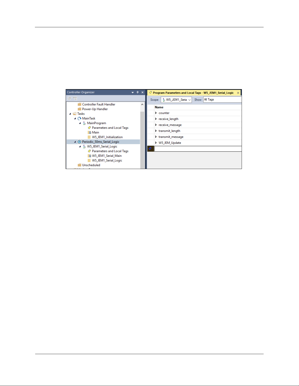
7. Navigate to the Tasks->Periodic_50ms_Serial_Logic->W5_JEM1_Serial_Logic->Parameters and
Local Tags window.
a. The tag “transmit_data” and “transmit_length” contain the message to be transmitted
Western Reserve Controls
W5-JEM1 Software Quick Start
Revision 1.0
4
PUB007-20190314-A01
b. The tag “receive_data” and “receive_length” contain the message that was received
i. Be aware that for production applications it is recommended to check the device’s
status bits (Controller Tags->W5_JEM1_Object->Receive_Message_Status and
Module_Status) prior to transmission and reception. This step has been omitted
from the demo for simplicity.
Figure 1. Parameters and Local Tags section in the example program showing the
transmit_* and receive_* tags
Note: The example program can easily be modified to serve as a starting point for applications using
the W5-JEM1
Western Reserve Controls
W5-JEM1 Software Quick Start
Revision 1.0
5
PUB007-20190314-A01
2 Software Configuration and Set-Up
2.1 Adding the Device to RSLogix or Studio 5000
Prior to adding the device to a project, it is necessary to install the device’s EDS file in Studio 5000.
See section 1.1 “Installing the Device EDS file in RSLogix or Studio 5000” for more details
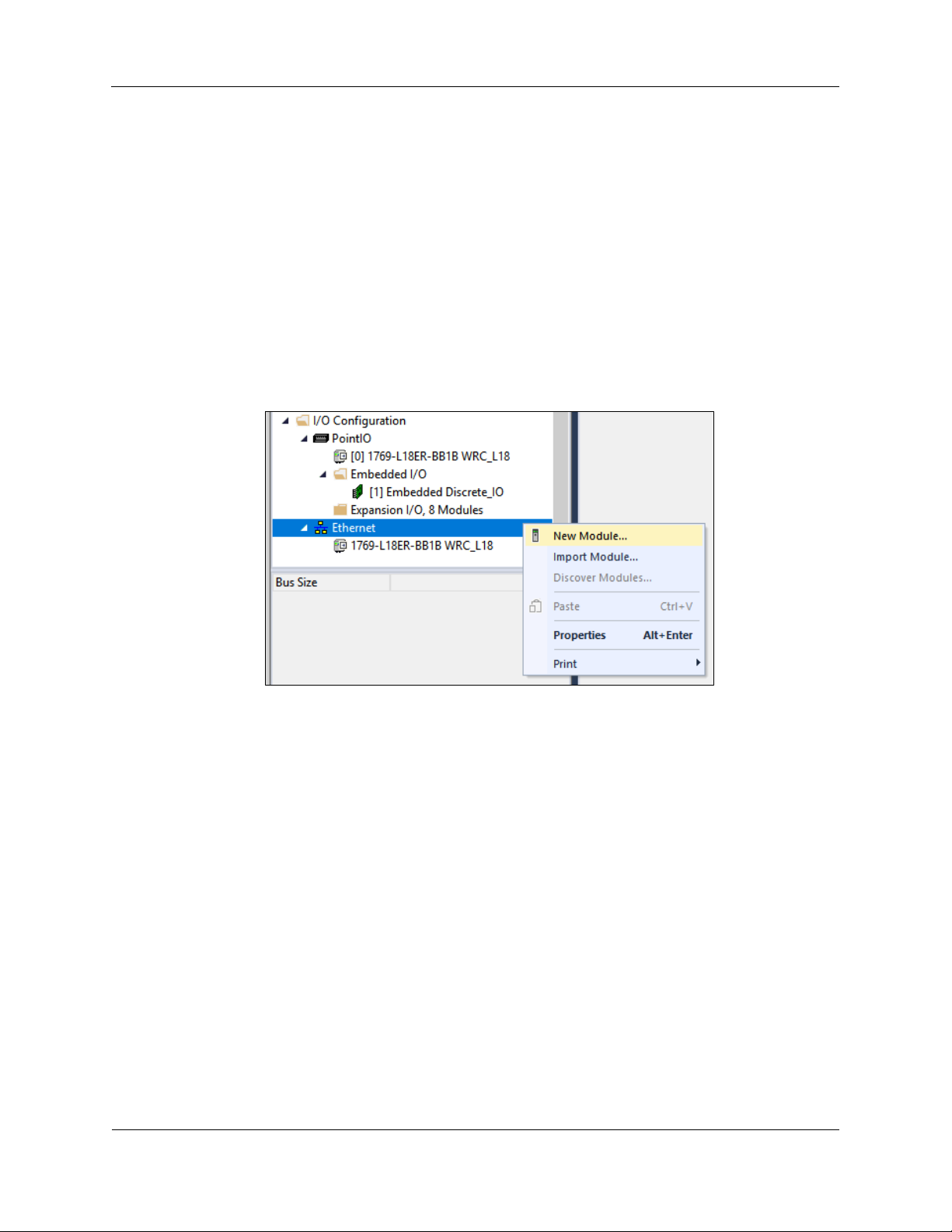
1. In the Controller Organizer Pane navigate to “I/O Configuration”
2. This part changes depending on your controller: typically, one can right-click under “Ethernet”
and select “New Module”. On some models of PLC that use an external ethernet adapter it
may be necessary to navigate and right click on the Ethernet Adapter.
Figure 2. Adding a new Module to the I/O Configuration
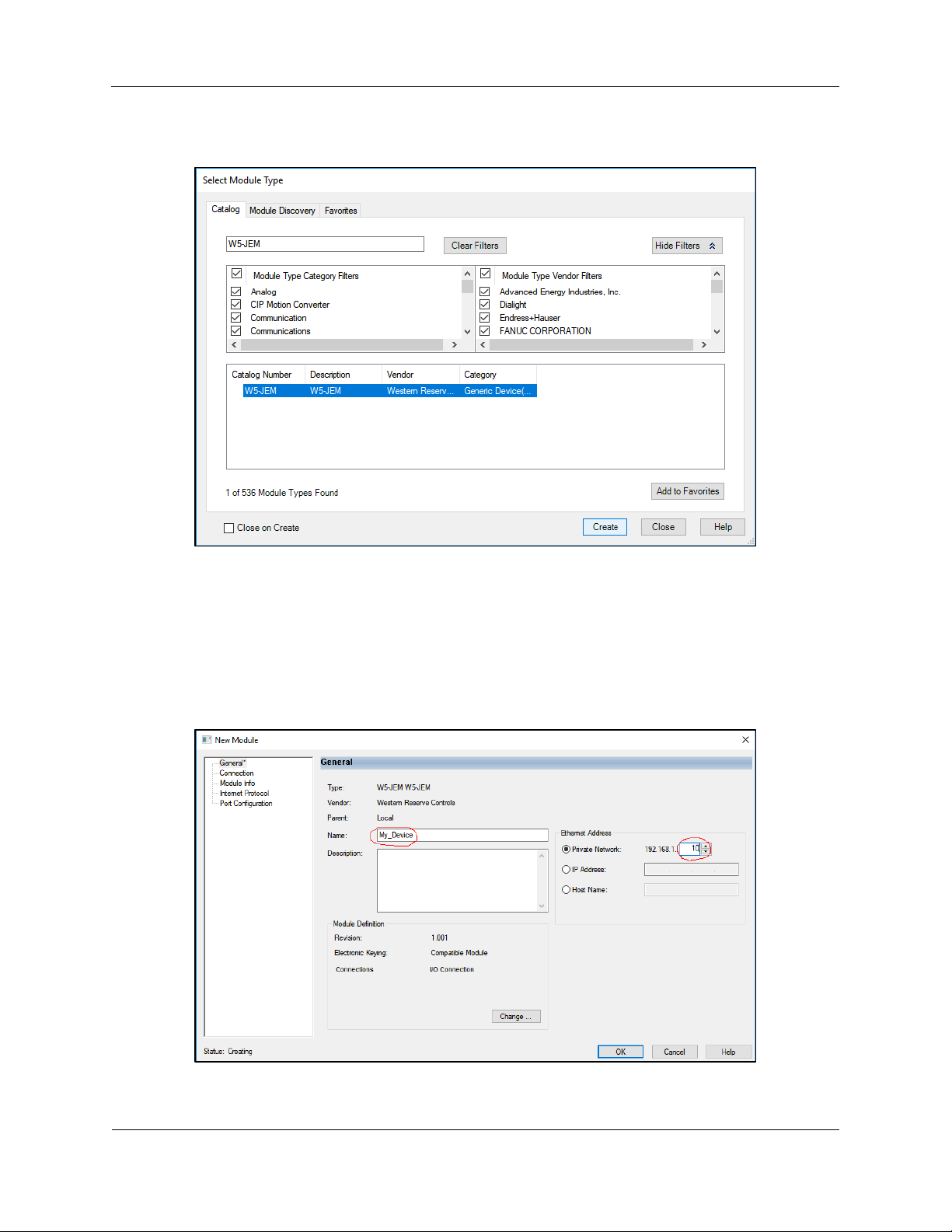
3. The “Select Module Type” dialog will open. Type in “W5-JEM” into the filter bar and select
the W5-JEM1 from the list. Click Create.
Western Reserve Controls
W5-JEM1 Software Quick Start
Revision 1.0
6
PUB007-20190314-A01
Figure 3. Finding the W5-JEM1 in the Select Module Type Dialog
4. The “New Module” dialog will open.
o Under the General Tab enter a device name such as “My_Device”
o Select the “Private Network” radio button and enter “10” in to the private address
textbox. This will tell the controller to look for the device at 192.168.1.10
Figure 4. Setting the device name and IP address
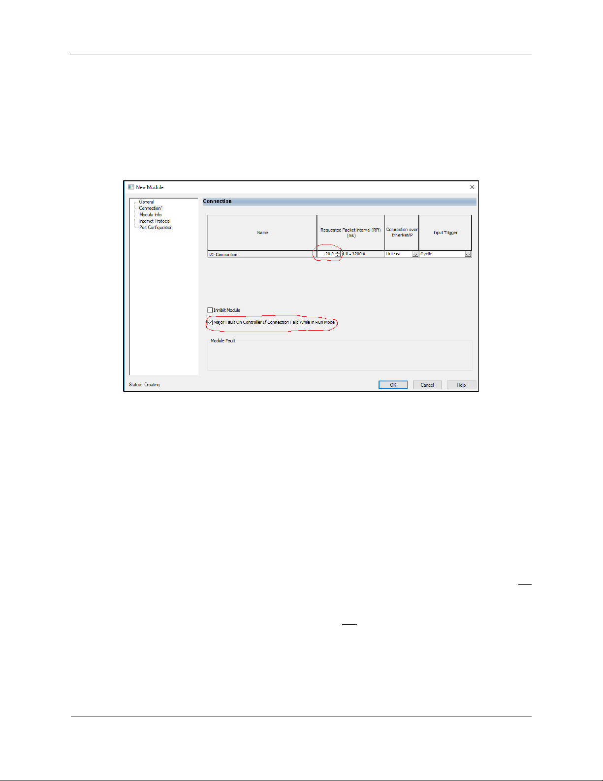
5. Under the Connection Tab inspect the Requested Packet Interval (RPI) field. The value of
the field controls how fast the controller can communicate with the W5-JEM1. The default
Western Reserve Controls
W5-JEM1 Software Quick Start
Revision 1.0
7
PUB007-20190314-A01
value of 20ms is fine for most applications. See section 2.2 “Determining Module RPI” for
more information about this field
6. Also under the Connection Tab (optionally) check the box “Major Fault On Controller If
Connection Fails While in Run Mode.” Most applcations using the W5-JEM1 need to be
aware if the EtherNet/IP link between the PLC and the device has been broken. A fault
handler can be implemented if required by the applcation.
Figure 5. Setting the RPI and Enabling Fault Upon I/O Connection Failure
2.2 Determining Module RPI
The RPI (Requested Packet Interval) is that rate at which the PLC and the W5-JEM1 communicate.
As a rule of thumb, it takes up to two RPI intervals for the command to transmit to propagate from the PLC
program to the W5-JEM1 over EtherNet/IP. When the W5-JEM1 receives a packet, it takes up to two RPI
intervals for the packet to be transferred over EtherNet/IP and recognized by the PLC program.
Characterizing the maximum throughput of the connection is achieved by connecting the W5-JEM1 in
loopback (ie. connect RX and TX pins). In this configuration the time T required to transmit and receive a
packet (steady state, one at a time, not using the FIFO buffers) is roughly where RPI is the
packet interval in seconds and S is the time it takes to transmit the serial packet on the serial bus.
The RPI required to send a packet and receive a packet every T seconds can be calculated via:
where S is the time the packet occupies on the serial bus
The value of S can be calculated by the following formula
where N is the number of bits per serial
frame (either 10 or 11 bits), M is the number of bytes per serial packet (typically 1-255 bytes) and B is the
baud rate (typically 1200-115200 baud).
Shown below is a table of time required to transmit and received a single packet versus baud rate at a 5ms
RPI. This table assumes a 16 byte packet in loopback using the 8N1 frame format.

Western Reserve Controls
W5-JEM1 Software Quick Start
Revision 1.0
8
PUB007-20190314-A01
Table 1. Loopback performance for 16 byte packets, 8N1, and RPI=5ms
Baud Rate
Time for transmit
command to
transfer over
EtherNet/IP (2x
RPI)
Time it takes to
transmit packet
over serial bus
Time for received
packet to transfer
over EtherNet/IP
(2x RPI)
Total Time to Transmit and
Receive in Loopback
115200
10ms
2ms
10ms
22ms
19200
10ms
9ms
10ms
29ms
9600
10ms
17ms
10ms
37ms
Baud
Rate
Time for
transmit
command to
transfer over
EtherNet/IP (2x
RPI)
Time it takes to
transmit packet
over serial bus
Time for received
packet to transfer
over EtherNet/IP (2x
RPI)
Total Time to Transmit
and Receive in Loopback
115200
40ms
2ms
40ms
82ms
19200
40ms
9ms
40ms
89ms
9600
40ms
17ms
40ms
97ms
Table 2. Loopback performance for 16 byte packets, 8N1, and RPI=20ms
NOTE: The throughputs demonstrated here are more than sufficient for most applications. However, if
faster times are required the W5-JEM1 supports RPIs as low as 1ms. Verify that your PLC controller
supports low RPI values before using an RPI below 5ms.
 Loading...