

Western Reserve Controls W5-JEM1 Installation Instructions

Wiring & Installation Instructions
W5-JEM1
EtherNet/IP to RS-232/485
Serial Device Gateway
Cost-optimized, multi-protocol, ASCII gateway
perfect for RS-232/485 Serial Device Integration
Document PUB005-20190314-A01
Rev 1.00
March 2019
Copyright © 2019 WRC
Western Reserve Controls, Inc.
© Western Reserve Controls, Inc.
PUB005-20190314-A01

Western Reserve Controls
W5-JEM1 Wiring & Installation
Revision 1.0
2
1 General Specifications
EtherNet/IP Device Profile:
Generic Device Type 0x2B (2B hex)
EtherNet/IP: Conformance:
Conforms to the ODVA EtherNet/IP Specification Version 1.23
Ethernet Link Speed:
10/100 MBits
IP Address selection:
Static IP configured via web browser (Factory Default: 192.168.1.10)
Power Supply:
5.0 – 28.0 Vdc
1A user replaceable fuse (spare fuse included)
Maximum Power:
2.4W, 100mA @ 24Vdc supply, 480mA @ 5Vdc supply
Minimum RPI:
4ms*
Serial Port Isolation
1000V DC Isolation
Size:
W5-JEM1-DH2: 2.000”x2.575”x 4.950” without connectors attached
Operating Temp:
-40 to +70 C
Humidity:
0-95% RH, non-condensing
RoHS:
Yes (RoHS 2)
CE Mark:
No
1.1 Table of Specifications
* Faster RPI values may be supported by certain PLC controllers.
PUB005-20190314-A01
Western Reserve Controls
W5-JEM1 Wiring & Installation
Revision 1.0
3
Hardware Installation and Set-Up
1.2 Installation
Follow the steps below:
1. In most cases it is recommended to set the device’s IP address prior to installation. See W5-JEM1
User Manual for complete instructions.
a. Note: factory default IP address is 192.168.1.10 for all units
2. Mount unit onto DIN rail
3. Wire up power (24VDC typical), common, and chassis ground to the power connector. See
“Connector Pinouts” for a diagram.
a. If there is no chassis ground connection, or the power supply is connected to chassis
ground, jumper the chassis ground connection to the common connection
4. Connect the device to the controlling PLC with an Ethernet cable
a. The device may be connected directly or through an ethernet switch
5. Connect the W5-JEM1 to the serial device using a compatible serial cable
a. This device requires serial cables with a special pinout. See section 1.8 “Serial Wiring
Diagrams” and section 1.7 “Connector Pinouts” for further information.
6. Apply power, device is ready for use with PLC.
7. Also see W5-JEM1 User Manual for an explanation of how to use the W5-JEM1 with a PLC
1.3 Power Supply
The device is intended to be used with standard 24V DC industrial power supplies. However, any voltage
between 5V and 28V may be supplied to the device assuming sufficient current is provided.
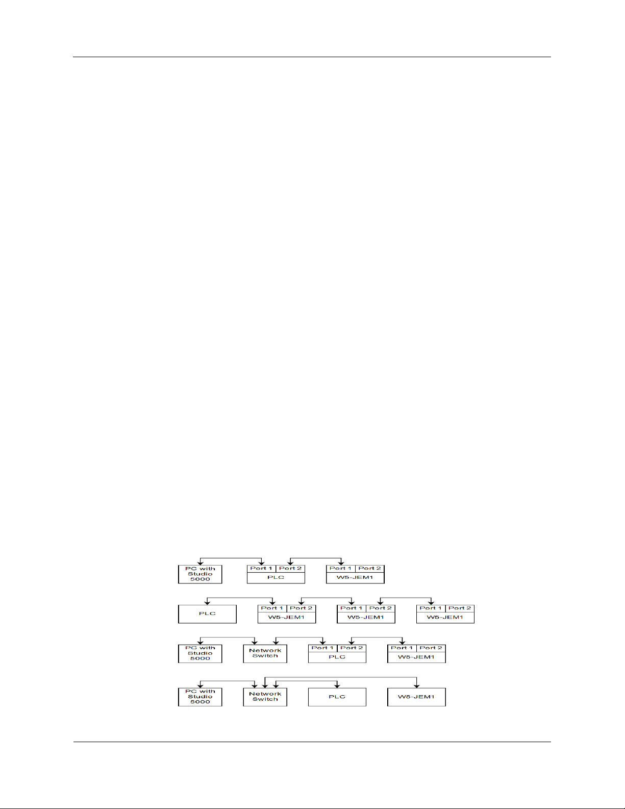
1.4 Network Connection
The device must be connected to the controlling PLC either directly with a cable or through your local
network Ethernet switch.
Figure 1. Several possible ethernet network configurations
PUB005-20190314-A01
 Loading...