

Western Reserve Controls W5-JEM Users Manual
User Manual
W5-JEM1
EtherNet/IP to RS-232/485
Serial Device Gateway
Cost-optimized, multi-protocol, ASCII gateway
perfect for RS-232/485 Serial Device Integration
© Western Reserve Controls, Inc.
PUB006-20190314-A01

Western Reserve Controls
W5-JEM1 User’s Manual
Revision 1.0
ii
PUB006-20190314-A01
Document PUB006-20190314-A01
The material in this document is for information purposes only. The content and the product it describes are
subject to change without notice. WRC makes no representation or warranties with respect to this
document. In no event shall WRC be held liable for technical or editorial omissions or mistakes in this
document, nor shall it be liable for any damages, direct or incidental, arising out of or related to the use of
this document. No part of this document may be reproduced in any form or by any means without the prior
written permission from WRC.
Rev 1.00
March 2019
Copyright © 2019 WRC
Western Reserve Controls, Inc.
WRC SerTek and the WRC logo are trademarks of Western Reserve Controls, Inc.
EtherNet/IP is a trademark of the ODVA.
All other trademarks are property of their respective companies.

Western Reserve Controls
W5-JEM1 User’s Manual
Revision 1.0
iii
PUB006-20190314-A01
Revision History
Revision
Date
Author
Section
Comments
1.0
3/14/2019
Jason White
John
Weisenberger
All
Initial Release
Western Reserve Controls

W5-JEM1 User’s Manual
Revision 1.0
iv
PUB006-20190314-A01
TABLE OF CONTENTS
1 OVERVIEW ................................................................................................................................................ 1
1.1 FEATURES ............................................................................................................................................... 2
1.2 TYPICAL APPLICATIONS ............................................................................................................................ 2
2 GENERAL SPECIFICATIONS ................................................................................................................... 3
2.1 TABLE OF SPECIFICATIONS ....................................................................................................................... 3
2.2 PRODUCT DRAWING, DIMENSIONS, AND PHOTOGRAPHS ............................................................................ 4
2.3 CONNECTOR PINOUTS ............................................................................................................................. 5
3 HARDWARE INSTALLATION AND SET-UP ............................................................................................ 7
3.1 INSTALLATION .......................................................................................................................................... 7
3.2 POWER SUPPLY ...................................................................................................................................... 7
3.3 NETWORK CONNECTION .......................................................................................................................... 7
3.4 LED INDICATORS ..................................................................................................................................... 8
3.5 SERIAL WIRING DIAGRAMS ..................................................................................................................... 10
4 SOFTWARE QUICK START ................................................................................................................... 12
4.1 INSTALLING THE DEVICE EDS FILE IN RSLOGIX OR STUDIO 5000 ............................................................ 12
4.2 LOADING THE EXAMPLE PROGRAM ......................................................................................................... 12
5 SOFTWARE CONFIGURATION AND SET-UP ...................................................................................... 14
5.1 ADDING THE DEVICE TO RSLOGIX OR STUDIO 5000 ................................................................................ 14
5.2 DETERMINING MODULE RPI ................................................................................................................... 16
5.3 THE AOI (ADD-ON-INSTRUCTION) FOR ROCKWELL PLCS ........................................................................ 18
5.3.1 Provided Add-On Instructions ....................................................................................................... 18
5.3.2 Provided Add-On Datatypes.......................................................................................................... 19
5.3.3 Configuration of the W5-JEM1 using the AOI ............................................................................... 24
5.3.4 Transmitting using the AOI ............................................................................................................ 25
5.3.5 Receiving using the AOI ................................................................................................................ 26
5.3.6 Setting up a PLC Project to use the W5-JEM1 AOIs and UDTs ................................................... 26
5.3.7 Troubleshooting the Add-On Instruction provided with the Example Program ............................. 30
5.4 USING THE MSG INSTRUCTION ON ROCKWELL PLCS .............................................................................. 31
5.5 INTERFACING THE DEVICE WITH OTHER PLCS ......................................................................................... 31
5.6 RESET BUTTON OPERATION ................................................................................................................... 31

Western Reserve Controls
W5-JEM1 User’s Manual
Revision 1.0
v
PUB006-20190314-A01
5.7 SETTING THE DEVICE IP ADDRESS ......................................................................................................... 32
5.7.1 Configuring your PC with a Static IP Address ............................................................................... 32
5.7.2 Setting Device IP Address Using Webpage .................................................................................. 34
5.8 UPGRADING FIRMWARE ......................................................................................................................... 35
6 ETHERNET/IP INTERFACE .................................................................................................................... 39
6.1 IMPLEMENTED OBJECTS ......................................................................................................................... 40
6.2 ASSEMBLY OBJECT INSTANCES .............................................................................................................. 40
6.3 CONFIGURATION ASSEMBLY FORMAT ..................................................................................................... 40
6.4 TRANSMIT ASSEMBLY FORMAT ............................................................................................................... 42
6.5 RECEIVE ASSEMBLY FORMAT ................................................................................................................. 42
6.6 DEVICE PARAMETERS ............................................................................................................................ 42
6.6.1 Idle Bit ............................................................................................................................................ 44
6.6.2 Mode Parameter ............................................................................................................................ 45
6.6.3 Frame Format ................................................................................................................................ 46
6.6.4 Baud Rate ...................................................................................................................................... 46
6.6.5 Hardware Flow Control .................................................................................................................. 46
6.6.6 RX Max Length .............................................................................................................................. 46
6.6.7 TX Record Number ....................................................................................................................... 46
6.6.8 RX Record Number ....................................................................................................................... 47
6.6.9 TX Data ......................................................................................................................................... 47
6.6.10 RX Data ....................................................................................................................................... 48
6.6.11 RX Timeout.................................................................................................................................. 48
6.6.12 TX Delay ...................................................................................................................................... 49
6.6.13 RX Maximum Intercharacter Spacing ......................................................................................... 50
6.6.14 TX Start Delimiter and TX End Delimiter ..................................................................................... 51
6.6.15 RX Start Delimiter and RX End Delimiter .................................................................................... 51
6.6.16 Status Bits ................................................................................................................................... 52
7 MODELS AND PART NUMBERS ........................................................................................................... 53

Western Reserve Controls
W5-JEM1 User’s Manual
Revision 1.0
vi
PUB006-20190314-A01
TABLE OF FIGURES
FIGURE 1. W5-JEM1 ....................................................................................................................................... 1
FIGURE 2. PRODUCT DRAWINGS, DIMENSIONS AND PHOTOGRAPHS ................................................................... 4
FIGURE 3. POWER CONNECTOR PINOUT ........................................................................................................... 5
FIGURE 4. MALE DE-9 SERIAL CONNECTOR PINOUT.......................................................................................... 5
FIGURE 5. SEVERAL POSSIBLE ETHERNET NETWORK CONFIGURATIONS .............................................................. 8
FIGURE 6. RS-232 WIRING DIAGRAM – MODULE TO DTE DEVICE (HARDWARE HANDSHAKING DISABLED). ........ 10
FIGURE 7. RS-232 WIRING DIAGRAM – MODULE TO PRINTER (HARDWARE HANDSHAKING ENABLED, STANDARD PRINTER
ADAPTER CABLE.). ................................................................................................................................. 10
FIGURE 8. RS-422 WIRING DIAGRAM.............................................................................................................. 11
FIGURE 9. RS-485 WIRING DIAGRAM.............................................................................................................. 11
FIGURE 10. PARAMETERS AND LOCAL TAGS SECTION IN THE EXAMPLE PROGRAM SHOWING THE TRANSMIT_* AND RECEIVE_*
TAGS ..................................................................................................................................................... 13
FIGURE 11. ADDING A NEW MODULE TO THE I/O CONFIGURATION .................................................................... 14
FIGURE 12. FINDING THE W5-JEM1 IN THE SELECT MODULE TYPE DIALOG ..................................................... 15
FIGURE 13. SETTING THE DEVICE NAME AND IP ADDRESS................................................................................. 15
FIGURE 14. SETTING THE RPI AND ENABLING FAULT UPON I/O CONNECTION FAILURE ..................................... 16
FIGURE 15. CONFIGURING THE W5_JEM1_RECONFIGURE TAG ....................................................................... 26
FIGURE 16. SELECTING MODULE RECONFIGURE IN THE MESSAGE CONFIGURATION DIALOG .............................. 27
FIGURE 17. SELECTING THE W5-JEM1 MODULE IN THE MESSAGE PATH BROWSER DIALOG .............................. 27
FIGURE 18. IMPORTING THE ADD-ON INSTRUCTIONS ....................................................................................... 28
FIGURE 19. SETTING THE PARAMETERS FOR THE W5_JEM1_INITIALIZE ADD-ON INSTRUCTION ......................... 29
FIGURE 20. SETTING THE PARAMETERS FOR THE W5_JEM1_UPDATE ADD-ON INSTRUCTION ........................... 29
FIGURE 21. OPEN NETWORK CONNECTIONS .................................................................................................. 32
FIGURE 22. SELECT INTERNET PROTOCOL VERSION 4 IN ETHERNET PROPERTIES ............................................ 33
FIGURE 23. SELECT AND SPECIFY STATIC IP ADDRESS ................................................................................... 33
FIGURE 24. DEVICE HOME PAGE .................................................................................................................... 34
FIGURE 25. REBOOT AFTER CLICKING SUBMIT ................................................................................................. 35
FIGURE 26. FIRMWARE UPDATE MODE WEBPAGE ........................................................................................... 36
FIGURE 27. SELECT FIRMWARE FILE .............................................................................................................. 37
FIGURE 28. DOWNLOADING FIRMWARE FILE ................................................................................................... 38
FIGURE 29. FIRMWARE DOWNLOAD COMPLETE .............................................................................................. 38
FIGURE 30. PROGRAM MODE/ RUN MODE/TEST MODE .................................................................................... 45
FIGURE 31. PLC MODE VERSUS IDLE BIT BEHAVIOR ....................................................................................... 45

Western Reserve Controls
W5-JEM1 User’s Manual
Revision 1.0
vii
PUB006-20190314-A01
FIGURE 32. TX BUFFERING SETUP ................................................................................................................. 47
FIGURE 33. RX BUFFERING SETUP ................................................................................................................. 48
FIGURE 34. GRAPH SHOWING HOW THE TIMING IS MEASURED FOR RX TIMEOUT ................................................ 49
FIGURE 35. GRAPH SHOWING THE OPERATION OF THE RX TIMEOUT FEATURE ................................................... 49
FIGURE 36. GRAPH SHOWING HOW THE TIMING IS MEASURED FOR TX DELAY .................................................... 50
FIGURE 37. GRAPH SHOWING HOW THE TIMING IS MEASURED FOR RX MAXIMUM INTERCHARACTER SPACING ..... 51
FIGURE 38. GRAPH DEFINING THE TIMING WINDOWS AND BEHAVIORS FOR RX MAXIMUM INTERCHARACTER SPACING
............................................................................................................................................................. 51
LIST OF TABLES
TABLE 1. POWER CONNECTOR PINOUT ............................................................................................................. 5
TABLE 2. SERIAL CONNECTOR PINOUT .............................................................................................................. 6
TABLE 3. OVERVIEW OF LED INDICATORS ......................................................................................................... 8
TABLE 4. MODULE STATUS LED (LABELED MS) ................................................................................................. 9
TABLE 5. ETHERNET/IP NETWORK STATUS LED (LABELED NS) ......................................................................... 9
TABLE 6. D-SUB CONNECTOR PINS ................................................................................................................. 10
TABLE 7. LOOPBACK PERFORMANCE FOR 16 BYTE PACKETS, 8N1, AND RPI=5MS ............................................. 17
TABLE 8. LOOPBACK PERFORMANCE FOR 16 BYTE PACKETS, 8N1, AND RPI=20MS ........................................... 17
TABLE 9. PROVIDED ADD-ON-INSTRUCTIONS .................................................................................................. 18
TABLE 10. PROVIDED ADD-ON DATATYPES ..................................................................................................... 19
TABLE 11. W5_JEM1_OBJECT DATATYPE..................................................................................................... 19
TABLE 12. W5_JEM1_CONFIGURATION DATATYPE ........................................................................................ 20
TABLE 13. W5_JEM1_MESSAGE_STATUS DATATYPE .................................................................................... 22
TABLE 14. W5_JEM1_MODULE_STATUS DATATYPE ...................................................................................... 22
TABLE 15. CONFIGURING THE DEVICE THROUGH THE W5_JEM1_OBJECT.CONFIGURATION TAG ....................... 25
TABLE 16. TROUBLESHOOTING THE AOI/EXAMPLE PROGRAM .......................................................................... 30
TABLE 17. RESET BUTTON FUNCTIONS ........................................................................................................... 32
TABLE 18. IMPLEMENTED ETHERNET/IP OBJECTS ........................................................................................... 40
TABLE 19. SUPPORTED ASSEMBLY OBJECT INSTANCES ................................................................................... 40
TABLE 20. CONFIGURATION ASSEMBLY FORMAT ............................................................................................. 41
TABLE 21. TRANSMIT ASSEMBLY FORMAT ....................................................................................................... 42
TABLE 22. RECEIVE ASSEMBLY FORMAT ......................................................................................................... 42
TABLE 23 DEVICE PARAMETERS ..................................................................................................................... 43

Western Reserve Controls
W5-JEM1 User’s Manual
Revision 1.0
viii
PUB006-20190314-A01
TABLE 24. EFFECTS OF THE MODE PARAMETER .............................................................................................. 45
TABLE 25. RX RECORD BEHAVIOR WHEN A PACKET IS RECEIVED .................................................................... 47
TABLE 26. RX RECORD BEHAVIOR WHEN RX RECORD NUMBER IS UPDATED ................................................... 47
TABLE 27. EXPLANATION OF STATUS BIT BEHAVIORS ...................................................................................... 52
Western Reserve Controls
W5-JEM1 User’s Manual
Revision 1.0
1
PUB006-20190314-A01
1 Overview
The W5-JEM1 is a single-channel EtherNet/IP to Serial Device Gateway that provides a flexible EtherNet/IP
interface to one or more ASCII or Modbus devices. This permits it to interface with a wide variety of TIA/EIA232 (RS-232), TIA/EIA-422 (RS-422), and TIA/EIA-485 (RS-485) devices.
The W5-JEM1 does not interpret the data being transmitted across it, and so the transferred messages
may contain data of any nature or definition. This allows you to use the same gateway for many different
serial protocols.
The W5-JEM1 permits communication with serial peripheral devices in the same fashion as the other
EtherNet/IP products in the system. Data may be read/written using either I/O messaging or explicit
messaging.
The W5-JEM1 has a 9-pin D-sub connector for connection to the serial interface port on your devices, two
RJ45 connectors for connections to the EtherNet/IP network, and one 3-pin connector for power and
grounding. The W5-JEM1 serial parameters are software-configurable. Each W5-JEM1 has 2 standard
green/red EtherNet/IP LED’s for module status and network status and two green LED’s for each serial port
to indicate transmit and receive activity.
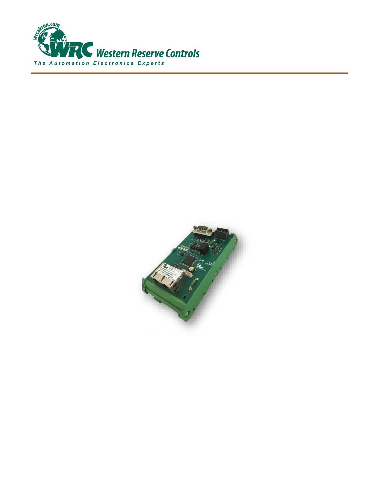
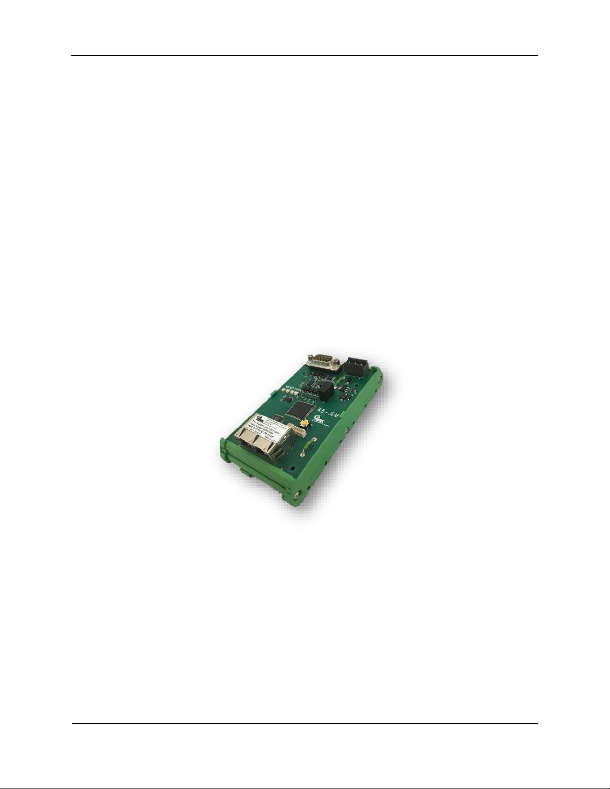
Figure 1. W5-JEM1

Western Reserve Controls
W5-JEM1 User’s Manual
Revision 1.0
2
PUB006-20190314-A01
1.1 Features
The W5-JEM1 has the following features:
• Translates between serial and EtherNet/IP permitting devices to be controlled via PLC or PC
• EtherNet/IP Conformance Tested by ODVA
• Embedded Ethernet switch with two RJ45 connectors for cost-saving daisy-chain network
topologies
• Embedded web server for easy IP address configuration and device status via web browser
• Configurable serial port supports generic ASCII/serial, Modbus ASCII or Modbus RTU
protocols
• Supports RTS/CTS hardware flow control for RS-232
• Configurable parameters for baud rate and frame format
• Serial Baud rates from 1200 to 115.2K baud
• Ethernet/IP packet ACK support for TX/RX between PLC and JEM
• Add on Instruction (AOI) for Rockwell PLCs
• 5-year Hardware Warranty
• WRC Evergreen™ Life Cycle Support Program
1.2 Typical Applications
• Weigh scales
• Power Monitors
• Torque Guns
• Barcode Scanners
• Printers
• SCADA Systems
• Mass Flow Controllers
• Lighting Controllers
• Variable Frequency Drives
• LED Message Signs
• HVAC Roof Top Units
• Dehumidification Units
• Robots
• Operator stations / HMI

Western Reserve Controls
W5-JEM1 User’s Manual
Revision 1.0
3
PUB006-20190314-A01
2 General Specifications
2.1 Table of Specifications
EtherNet/IP Device Profile:
Generic Device Type 0x2B (2B hex)
EtherNet/IP: Conformance:
Conforms to the ODVA EtherNet/IP Specification Version 1.23
Ethernet Link Speed:
10/100 MBits
IP Address selection:
Static IP configured via web browser (Factory Default: 192.168.1.10)
Power Supply:
5.0 – 28.0 Vdc
1A user replaceable fuse (spare fuse included)
Maximum Power:
2.4W, 100mA @ 24Vdc supply, 480mA @ 5Vdc supply
Minimum RPI:
4ms*
Serial Port Isolation
1000V DC Isolation
Size:
DH2: 2.000”x2.575”x 4.950” without connectors attached
Operating Temp:
-40 to +70 C
Humidity:
0-95% RH, non-condensing
RoHS:
Yes (RoHS 2)
CE Mark:
No
* Faster RPI values may be supported by certain PLC controllers.

Western Reserve Controls
W5-JEM1 User’s Manual
Revision 1.0
4
PUB006-20190314-A01
2.2 Product Drawing, Dimensions, and Photographs
Show below are the overall dimensions of the product when installed on a piece of standard DIN rail (DIN
rail not included with product). This drawing does not include the height or length added by the Power,
Serial, or Ethernet cables or their connectors.
Side View
Top View
Figure 2. Product Drawings, Dimensions and Photographs
Western Reserve Controls
W5-JEM1 User’s Manual
Revision 1.0
5
PUB006-20190314-A01
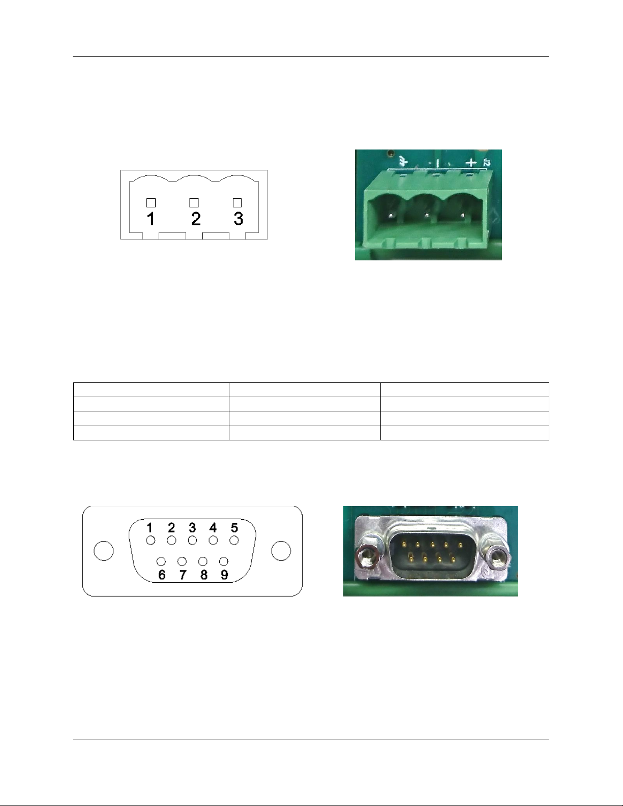
2.3 Connector Pinouts
Figure 3. Power Connector Pinout
Table 1. Power Connector Pinout
Pin
Name
Description
1
GND
Chassis Ground
2
V- (COM)
Power Common
3
V+
Power In, 5V-28V
Figure 4. Male DE-9 Serial Connector Pinout

Western Reserve Controls
W5-JEM1 User’s Manual
Revision 1.0
6
PUB006-20190314-A01
ATTENTION: You must use a cable that matches the specifications shown in the
table below.
Table 2. Serial Connector Pinout
DE9 Pin #
RS-232
RS-422
RS-485
1
Do Not Connect
Transmit Data –
Transmit/Receive Data –
2
Receive Data
Do Not Connect
Do Not Connect
3
Transmit Data
Do Not Connect
Do Not Connect
4
Do Not Connect
Receive Data –
Do Not Connect
5
Common
Common
Common
6
Do Not Connect
Receive Data +
Do Not Connect
7
Request to Send
Request to Send*
Request to Send*
8
Clear to Send
Clear to Send*
Clear to Send*
9
Do Not Connect
Transmit Data +
Transmit/Receive Data +
*RTS and CTS are not supported in RS-422 and RS-485. These connections must be connected together at the JEM1 Device

Western Reserve Controls
W5-JEM1 User’s Manual
Revision 1.0
7
PUB006-20190314-A01
3 Hardware Installation and Set-Up
3.1 Installation
Follow the steps below:
1. In most cases it is recommended to set the device’s IP address prior to installation. See section
5.7 “Setting the Device IP Address” if required.
a. The factory default IP address is 192.168.1.10 for all units
2. Mount unit onto DIN rail
3. Wire up power (24VDC typical), common, and chassis ground to the power connector. See section
2.3 “Connector Pinouts” for a diagram.
a. If there is no chassis ground connection or the power supply is connected to chassis
ground, jumper the chassis ground connection to the common connection
4. Connect the device to the controlling PLC with an Ethernet cable
a. The device may be connected directly or through an ethernet switch
5. Connect the W5-JEM1 to the serial device using a compatible serial cable
a. This device requires serial cables with a special pinout. See section 3.5 “Serial Wiring
Diagrams” and section 2.3 “Connector Pinouts” for further information.
6. Apply power, device is ready for use with PLC.
7. Also see section 4 “Software Quick Start” for an explanation of how to use the W5-JEM1 with a
PLC
3.2 Power Supply
The device is intended to be used with standard 24V DC industrial power supplies. However, any voltage
between 5V and 28V may be supplied to the device assuming sufficient current is provided.
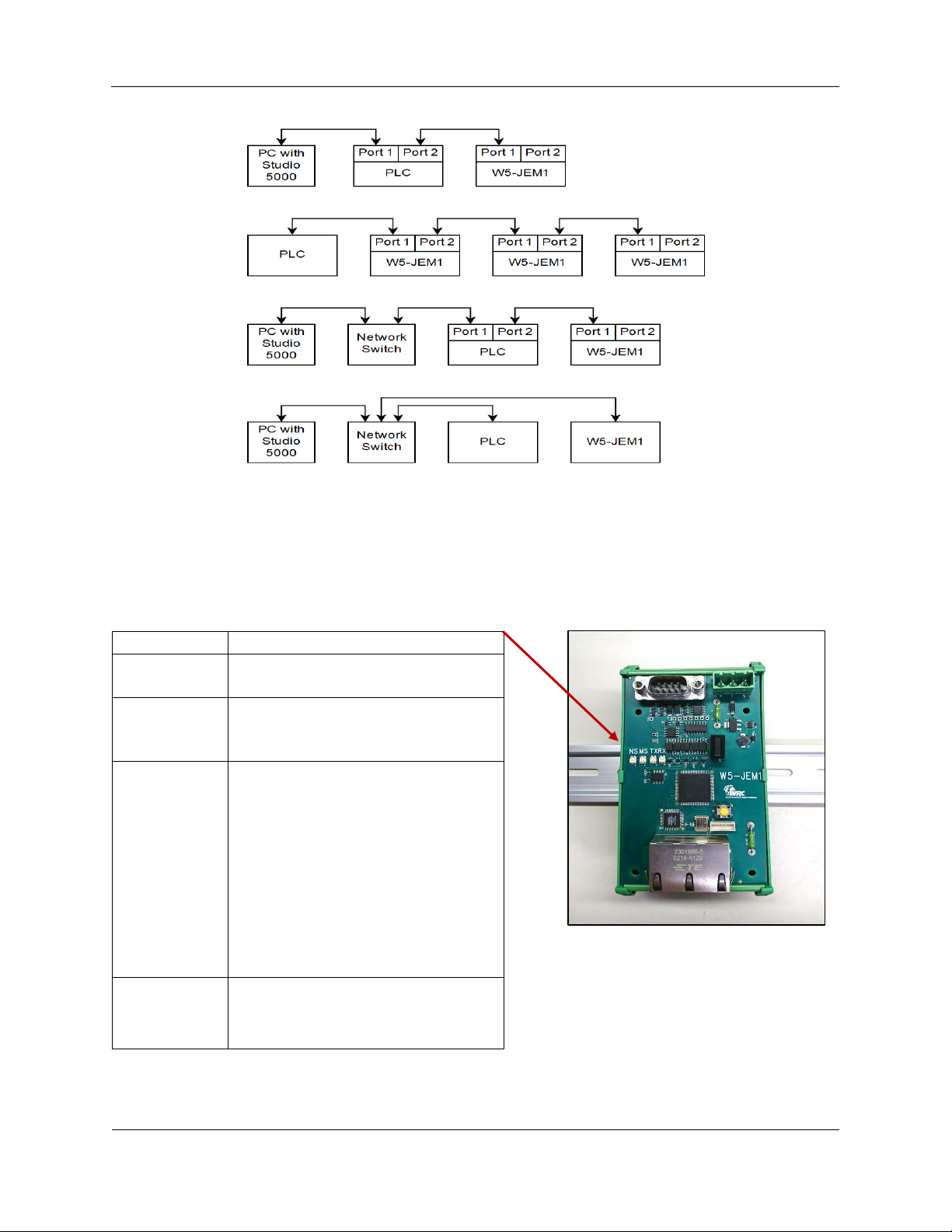
3.3 Network Connection
The device must be connected to the controlling PLC either directly with a cable or through your local
network Ethernet switch. Shown below is a diagram of some typical network setups when using a Rockwell
PLC.
Western Reserve Controls
W5-JEM1 User’s Manual
Revision 1.0
8
PUB006-20190314-A01
Figure 5. Several possible Ethernet network configurations
LED Name
Description
RX
Indicates when data is being
received on the serial line
TX
Indicates when data us being
transmitted by the W5-JEM1 onto the
serial line
MS
Indicates if the module is okay or if
there is an error. See
Table 4 below.
NS
Indicates if the network status. See
Table 5 below.
3.4 LED Indicators
Table 3. Overview of LED Indicators

Western Reserve Controls
W5-JEM1 User’s Manual
Revision 1.0
9
PUB006-20190314-A01
Table 4. Module Status LED (labeled MS)
LED State
Module Status
Meaning
Off
No Power
Device is not powered.
Green
Device Operational
W5-JEM1 is operating normally.
Flashing Red
Minor Fault
Recoverable fault.
Solid Red
Critical Fault
Device will automatically reboot to clear a
critical fault after 30 seconds.
Table 5. EtherNet/IP Network Status LED (labeled NS)
LED State
Network Status
Meaning
OFF
No Power
W5-JEM1 has no power
Flashing Green
Online, not connected
W5-JEM1 is online but is not connected to a
PLC.
Green
Online, connected
W5-JEM1 is operating normally and is
connected to a PLC
Flashing Red
Connection time-out
One or more connections are timed out.
Western Reserve Controls
W5-JEM1 User’s Manual
Revision 1.0
10
PUB006-20190314-A01
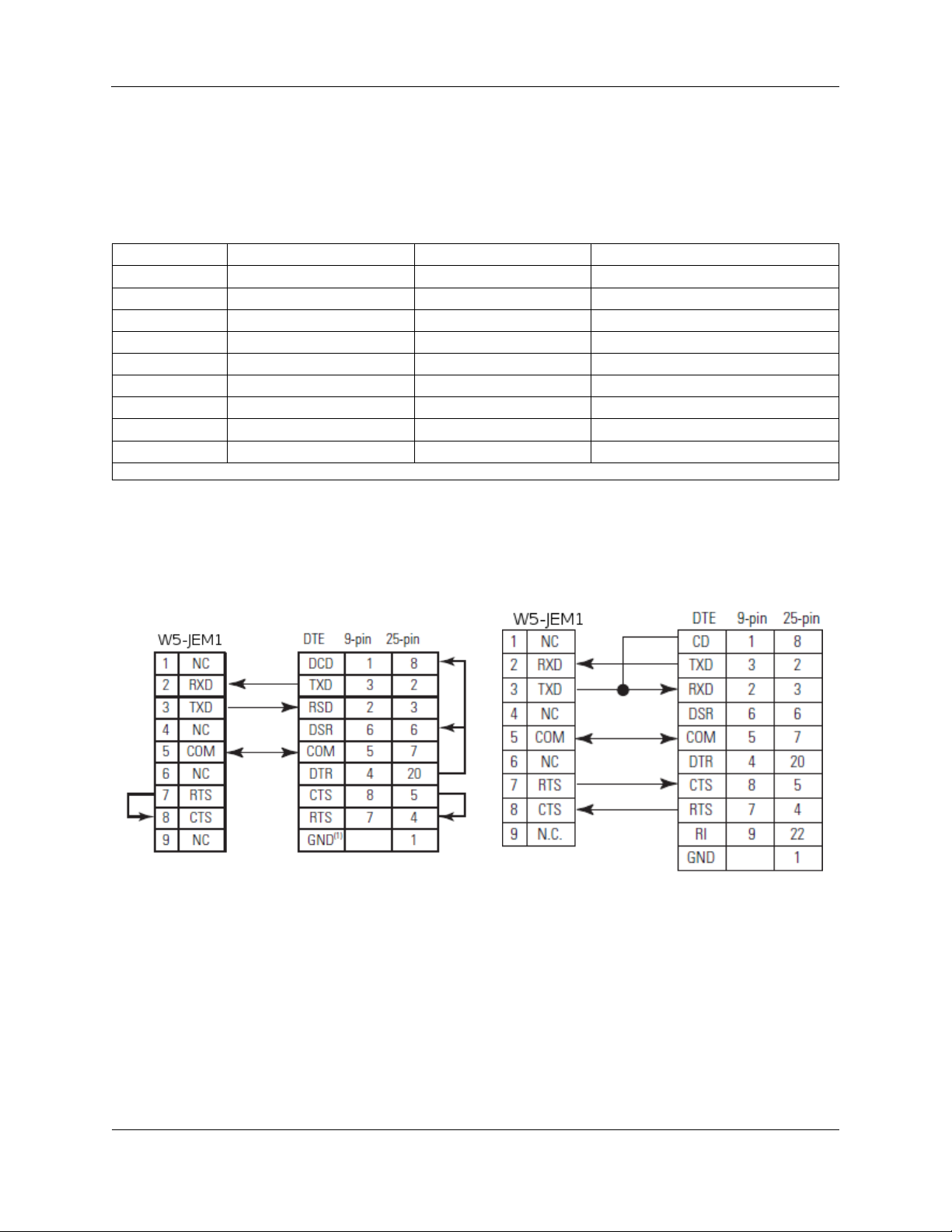
3.5 Serial Wiring Diagrams
The serial port can be operated as RS-232, RS-422, or RS-485 connection. Selection among RS-232, 422
or 485 is made by using the correct cable for the desired RS specification.
ATTENTION: You must use a cable that matches the specifications shown in the table below.
Table 6. D-sub Connector Pins
DB9 Pin #
RS-232
RS-422
RS-485
1
Do Not Connect
Transmit Data –
Transmit/Receive Data –
2
Receive Data
Do Not Connect
Do Not Connect
3
Transmit Data
Do Not Connect
Do Not Connect
4
Do Not Connect
Receive Data –
Do Not Connect
5
Common
Common
Common
6
Do Not Connect
Receive Data +
Do Not Connect
7
Request To Send
Request to Send*
Request to Send*
8
Clear To Send
Clear to Send*
Clear to Send*
9
Do Not Connect
Transmit Data +
Transmit/Receive Data +
*RTS and CTS are not supported in RS-422 and RS-485. These connections must be connected together at the JEM1 Device
Note: Pay attention to distance limitations based upon RS standards and baud rate.
Figure 6. RS-232 Wiring Diagram – Module to
DTE Device (Hardware Handshaking Disabled).
Figure 7. RS-232 Wiring Diagram – Module to
Printer (Hardware Handshaking Enabled,
Standard Printer Adapter Cable.)
Western Reserve Controls
W5-JEM1 User’s Manual
Revision 1.0
11
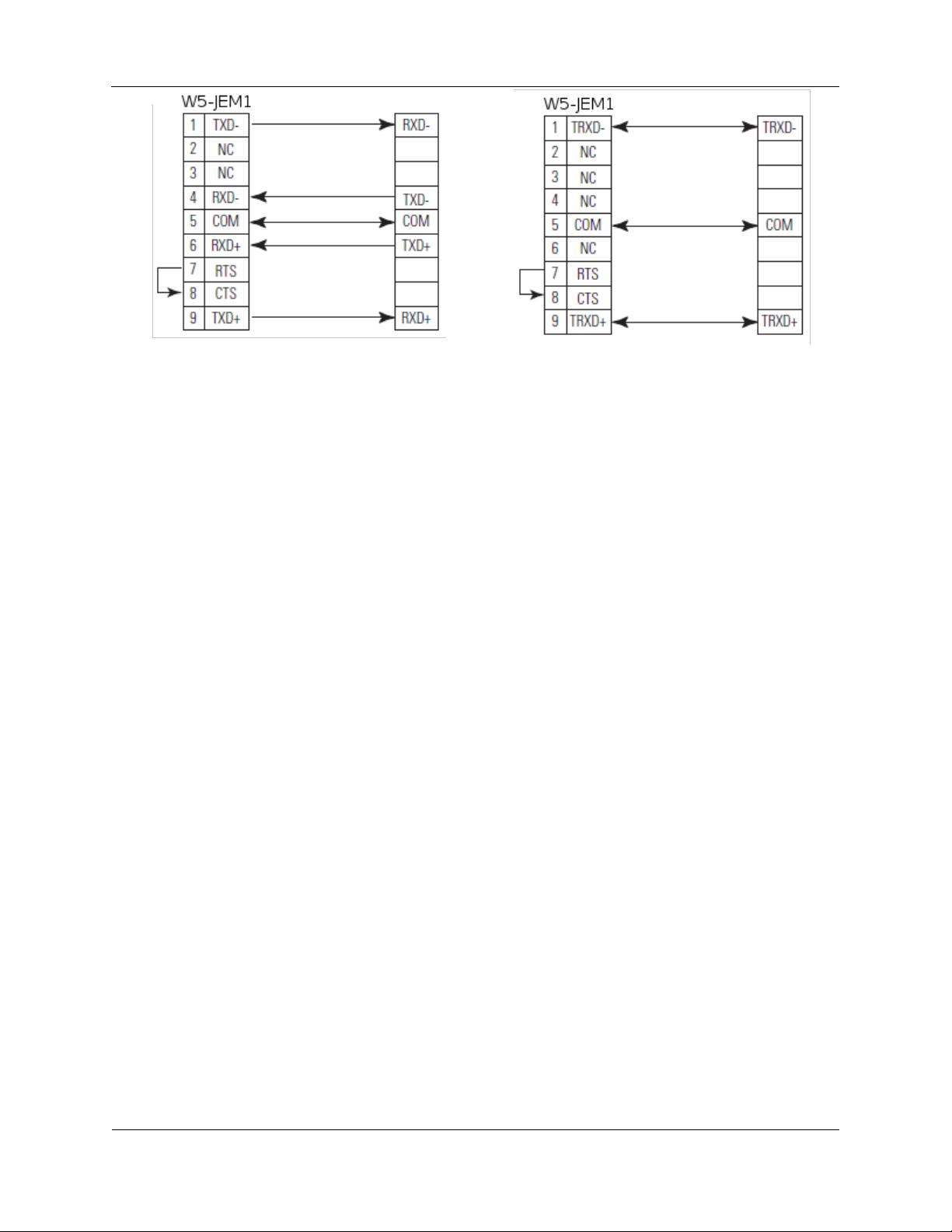
PUB006-20190314-A01
Figure 8. RS-422 Wiring Diagram
Figure 9. RS-485 Wiring Diagram
 Loading...