

Western Reserve Controls W5-JDC4 User Manual

W5-JDC4
Revision 1.02
4-Channel DeviceNet Serial
Gateway
User’s Manual
Western Reserve Controls

Western Reserve Controls W5-JDC4 User’s Manual
Revision 1.02
Although every effort has been made to insure the accuracy of this document, all information is subject
to change without notice. Western Reserve Controls Inc. assumes no liability for any errors or
omissions in this document or for direct, indirect, incidental or consequential damage resulting from the
use of this document.
Document PUB 32.0
Rev 1.02
March 2003
Copyright © 2003 Western Reserve Controls
Western Reserve Controls
1485 Exeter Rd.
Akron, Ohio 44306
http://www.wrcakron.com
DeviceNet is a trademark of the Open DeviceNet Vendor Association (“ODVA”).
All other trademarks are property of their respective companies.
i

Western Reserve Controls W5-JDC4 User’s Manual
Revision 1.02
TABLE OF CONTENTS
1 OVERVIEW...................................................................................................................................................................................1
1.1 FEATURES .................................................................................................................................................................................2
1.2 TYPICAL APPLICATIONS .......................................................................................................................................................3
1.3 BASIC OPERATION...................................................................................................................................................................3
1.3.1 Polled I/O ..........................................................................................................................................................................3
1.3.2 Cyclic Input Message.....................................................................................................................................................3
1.3.3 Change-of-State, or C.O.S.............................................................................................................................................4
1.3.4 Explicit Messages............................................................................................................................................................4
1.4 MAJOR OPTION SELECTIONS................................................................................................................................................4
1.4.1 Maximum Transmit and Receive Characters Parameters........................................................................................4
1.4.2 Master-Slave Handshake vs. Immediate Option........................................................................................................4
2 QUICK START.............................................................................................................................................................................5
2.1 HOW TO INSTALL AND ESTABLISH DEVICENET COMMUNICATIONS............................................................................5
2.2 DEFAULT SETTINGS................................................................................................................................................................6
2.3 HOW TO INSTALL A SERIAL NETWORK..............................................................................................................................7
2.4 HOW TO READ SERIAL DEVICE DATA FROM THE W5-JDC4..........................................................................................7
2.4.1 Example Assembly for Serial Receive..........................................................................................................................8
2.4.2 The Receive Max Character Length............................................................................................................................8
2.5 HOW TO WRITE SERIAL OUTPUT DATA TO THE W5-JDC4..........................................................................................9
2.5.1 Example Assembly for Serial Transmit........................................................................................................................9
2.5.2 The Transmit Max Character Length..........................................................................................................................9
3 GENERAL SPECIFICATIONS ................................................................................................................................................10
4 HARDWARE INSTALLATION AND SET-UP.....................................................................................................................12
4.1 OVERVIEW...............................................................................................................................................................................12
4.2 LED OPERATION....................................................................................................................................................................13
4.2.1 DeviceNet LEDs.............................................................................................................................................................13
4.2.2 Serial Port LEDs............................................................................................................................................................14
4.3 SERIAL PORT CONNECTOR ..................................................................................................................................................14
4.4 ROTARY SWITCHES...............................................................................................................................................................15
4.5 DEVICENET CONFIGURATION.............................................................................................................................................15
4.5.1 Network Termination...................................................................................................................................................16
4.5.2 DeviceNet Connection Wiring....................................................................................................................................16
5 SOFTWARE CONFIGURATION AND SET-UP ..................................................................................................................18
5.1 DEVICE PARAMETERS...........................................................................................................................................................18
5.2 SETTING UP THE SERIAL LINK...........................................................................................................................................18
5.3 RECEIVING SERIAL DATA FROM THE ASCII DEVICE......................................................................................................18
5.3.1 Overview.........................................................................................................................................................................18
5.3.2 Setting up the Receive Character Buffer Length.....................................................................................................18
5.3.3 Setting up and Using Pad Mode................................................................................................................................19
5.3.4 Setting Up and Using the Swap Bytes Mode............................................................................................................20
5.3.5 Setting Up and Using Delimiter Operation..............................................................................................................21
5.3.6 Receive String Data Type............................................................................................................................................21
5.3.7 Setting Up the Scanner I/O Receive Size..................................................................................................................22
5.3.8 Explicit Messages to Receive the Serial Data String.............................................................................................22
5.3.9 Status Byte Description................................................................................................................................................22
5.4 TRANSMITTING SERIAL DATA TO THE ASCII DEVICE..................................................................................................25
ii

Western Reserve Controls W5-JDC4 User’s Manual
Revision 1.02
5.4.1 Overview.........................................................................................................................................................................25
5.4.2 Setting up the Transmit Character Buffer Length...................................................................................................25
5.4.3 Setting Up and Using the Transmit Delimiter..........................................................................................................25
5.4.4 Setting up and using the TX Byte Swap Mode.........................................................................................................25
5.4.5 Transmitting from the Master to the W5-JDC4 ........................................................................................................26
5.4.6 Transmit String Data Type..........................................................................................................................................26
5.4.7 Transmitting Serial Data.............................................................................................................................................26
5.4.8 Setting Up the Scanner I/O Transmit Size................................................................................................................26
5.4.9 Master-Slave Handshake vs. Immediate Mode........................................................................................................27
5.4.10 Explicit Messages to Transmit Serial Data String...............................................................................................28
5.5 SETTING UP DEVICENET COMMUNICATIONS..................................................................................................................28
5.5.1 Polled I/O ........................................................................................................................................................................28
5.5.2 Cyclic and Change-of-State I/O.................................................................................................................................28
5.5.3 Setting up the DeviceNet I/O Connections ...............................................................................................................29
5.5.4 Setting up the Connection Timer (EPR)...................................................................................................................29
5.5.5 Setting up the DeviceNet Baudrate...........................................................................................................................29
6 ASSEMBLY OBJECT FORMATS .........................................................................................................................................30
6.1 SHORT STRING DATA TYPE ASSEMBLIES .........................................................................................................................30
6.1.1 Immediate Mode............................................................................................................................................................30
6.1.2 Handshake Mode..........................................................................................................................................................30
6.2 ARRAY (DATA BLOCK) DATA TYPE ASSEMBLIES ..........................................................................................................31
6.2.1 Immediate Mode............................................................................................................................................................31
6.2.2 Handshake Mode..........................................................................................................................................................31
6.3 STRING DATA TYPE ASSEMBLIES......................................................................................................................................31
6.3.1 Immediate Mode............................................................................................................................................................31
6.3.2 Handshake Mode..........................................................................................................................................................31
7 THEORY OF OPERATION......................................................................................................................................................33
7.1 THE TRANSMIT RECORD ALGORITHM..............................................................................................................................33
7.1.1 Basic Theory of operation...........................................................................................................................................33
7.2 THE RECEIVE RECORD ALGORITHM ..................................................................................................................................33
7.2.1 Basic Theory of operation...........................................................................................................................................33
8 DEVICENET PROFILE, OBJECTS AND SERVICES .........................................................................................................36
8.1 W5 -JDC4 DEVICENET PROFILE..........................................................................................................................................36
8.2 IDENTITY OBJECT (CLASS 1)...............................................................................................................................................37
8.3 DEVICENET OBJECT (CLASS 3)............................................................................................................................................38
8.4 ASSEMBLY OBJECT (CLASS 4)..............................................................................................................................................40
8.4.1 Instance 101 (Consume) Assembly Object Description.........................................................................................40
8.4.2 Instance 102 (Produce) Assembly Object Description...........................................................................................41
8.4.3 Disabling channels.......................................................................................................................................................41
8.5 CONNECTION (CLASS 5) OBJECT ........................................................................................................................................42
8.6 ACKNOWLEDGE (CLASS 43) OBJECT ..................................................................................................................................42
8.7 SERIAL PORT OBJECT CLASS 112 (70
)...........................................................................................................................42
HEX
8.7.1 Serial Port Class Attributes........................................................................................................................................42
8.7.2 Serial Port Class Services...........................................................................................................................................42
8.7.3 Serial Port Instance Attributes...................................................................................................................................42
8.7.4 Instance Services...........................................................................................................................................................44
8.8 TRANSMIT RECORD OBJECT CLASS 113 (71
)................................................................................................................44
HEX
8.8.1 Transmit Record Object Class Attributes..................................................................................................................44
8.8.2 Transmit Record Object Class Services.....................................................................................................................44
8.8.3 Transmit Record Object Instance Attributes............................................................................................................45
iii

Western Reserve Controls W5-JDC4 User’s Manual
Revision 1.02
8.8.4 Transmit Record Object Instance Services...............................................................................................................47
8.9 RECEIVE RECORD OBJECT CLASS 114 (72
)....................................................................................................................47
HEX
8.9.1 Receive Record Object Class Attributes....................................................................................................................47
8.9.2 Receive Record Object Class Services.......................................................................................................................47
8.9.3 Receive Record Object Instance Attributes..............................................................................................................47
8.9.4 Receive Record Object Instance Services.................................................................................................................51
8.10 COMMON DEVICENET SERVICES......................................................................................................................................51
TABLE OF FIGURES
FIGURE 1-1 W5 -JDC4........................................................................................................................................................................1
FIGURE 4-1 W5 -JDC4 OUTLINE DRAWING – TOP VIEW..........................................................................................................12
FIGURE 4-2 W5 -JDC4 OUTLINE DRAWING – RIGHT SIDE VIEW ............................................................................................13
FIGURE 4-3 DEVICENET CONNECTORS ........................................................................................................................................17
FIGURE 5-1 RECEIVE ARRAY DATA FORMAT............................................................................................................................22
FIGURE 5-2 RECEIVE SHORT_STRING DATA FORMAT.............................................................................................................22
FIGURE 5-3 RECEIVE STRING DATA FORMAT............................................................................................................................22
FIGURE 7-1 TRANSMIT RECORD ALGORITHM FUNCTIONAL FLOWCHART..........................................................................33
FIGURE 7-2 RECEIVE RECORD ALGORITHM FUNCTIONAL FLOWCHART .............................................................................34
iv

Western Reserve Controls W5-JDC4 User’s Manual
Revision 1.02
LIST OF TABLES
TABLE 1-1 I/O MESSAGE TYPES......................................................................................................................................................3
TABLE 2-1 INSTANCES OF THE SERIAL CHANNELS.....................................................................................................................5
TABLE 2-2 DEFAULT INPUT (SERIAL RECEIVE) ASSEMBLY FORMAT ....................................................................................8
TABLE 2-3 DEFAULT OUTPUT (SERIAL TRANSMIT) ASSEMBLY FORMAT ............................................................................9
TABLE 4-1 MODULE STATUS LED (LABELED MS)...................................................................................................................13
TABLE 4-2 NETWORK STATUS LED (LABELED NS).................................................................................................................14
TABLE 4-3 RS232 CONNECTOR SIGNALS.....................................................................................................................................14
TABLE 4-4 BAUD RATE SWITCH (RATE) ...................................................................................................................................15
TABLE 4-5 DEVICENET ADDRESS SWITCHES.............................................................................................................................15
TABLE 4-6 MAXIMUM NETWORK CABLE LENGTHS.................................................................................................................16
TABLE 5-1 SERIAL STATUS BYTE................................................................................................................................................23
TABLE 5-2 W5 -JDC4 CONSUME ASSEMBLY OBJECT WITH HANDSHAKE MODE ................................................................27
TABLE 6-1 IMMEDIATE MODE CONSUME SHORT STRING......................................................................................................30
TABLE 6-2 IMMEDIATE MODE PRODUCE SHORT STRING.......................................................................................................30
TABLE 6-3 HANDSHAKE MODE CONSUME SHORT STRING.....................................................................................................30
TABLE 6-4 HANDSHAKE MODE PRODUCE SHORT STRING......................................................................................................30
TABLE 6-5 IMMEDIATE MODE CONSUME DATA BLOCK .........................................................................................................31
TABLE 6-6 IMMEDIATE MODE PRODUCE DATA BLOCK..........................................................................................................31
TABLE 6-7 HANDSHAKE MODE CONSUME DATA BLOCK ........................................................................................................31
TABLE 6-8 HANDSHAKE MODE PRODUCE DATA BLOCK.........................................................................................................31
TABLE 6-9 IMMEDIATE MODE CONSUME STRING....................................................................................................................31
TABLE 6-10 IMMEDIATE MODE PRODUCE STRING ..................................................................................................................31
TABLE 6-11 HANDSHAKE MODE CONSUME STRING.................................................................................................................31
TABLE 6-12 HANDSHAKE MODE PRODUCE STRING .................................................................................................................32
TABLE 8-1 DEVICENET OBJECTS..................................................................................................................................................36
TABLE 8-2 IDENTITY OBJECT CLASS ATTRIBUTES (INSTANCE 0).........................................................................................37
TABLE 8-3 IDENTITY OBJECT INSTANCE ATTRIBUTES (INSTANCE 1).................................................................................37
TABLE 8-4 IDENTITY OBJECT COMMON SERVICES..................................................................................................................38
TABLE 8-5 CLASS 3 CLASS ATTRIBUTES....................................................................................................................................38
TABLE 8-6 CLASS 3 INSTANCE ATTRIBUTES.............................................................................................................................39
TABLE 8-7 INSTANCE 101 CONSUME DATA (ASCII TRANSMIT STRING)..............................................................................40
TABLE 8-8 INSTANCE 102 PRODUCE DATA (ASCII RECEIVE STRING)..................................................................................41
TABLE 8-9 CHANNEL 2 DISABLED................................................................................................................................................41
TABLE 8-10 CLASS 112 (70
TABLE 8-11 CLASS 113 (71
TABLE 8-12 CLASS 114 (72
) SERIAL PORT OBJECT INSTANCE ATTRIBUTES...................................................................42
HEX
) TRANSMIT RECORD OBJECT INSTANCE ATTRIBUTES .......................................................45
HEX
) RECEIVE RECORD OBJECT INSTANCE ATTRIBUTES...........................................................47
HEX
v
Western Reserve Controls W5-JDC4 User’s Manual
Revision 1.02
1 Overview
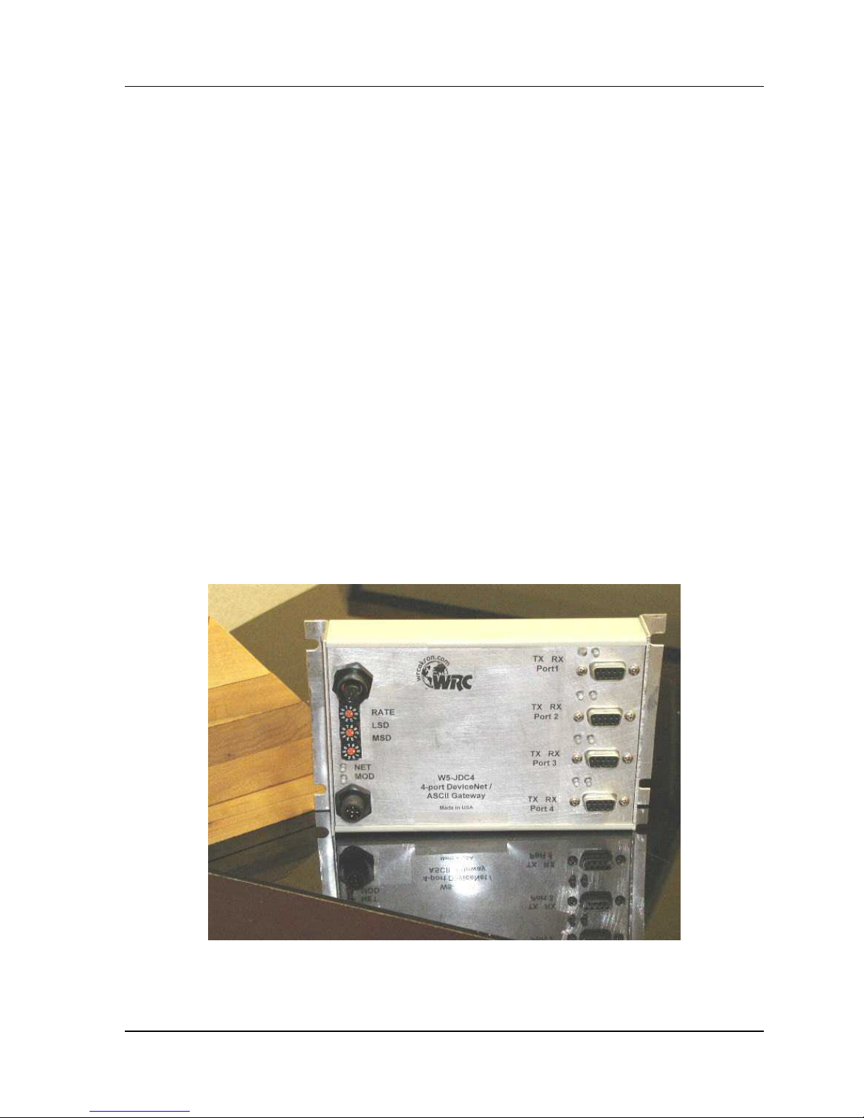
The W5-JDC4 is a panel-mounted DeviceNet -to-serial link communications gateway that provides a
flexible DeviceNet interface to as many as four different channels of ASCII devices. A wide variety of
serial ASCII devices can be easily connected, with independent setups for each channel.
The W5-JDC4 does not interpret the data being transmitted across it, and so the transferred
messages may contain data of any nature or definition. This allows you to use the same gateway
for many different serial protocols.
Using the W5-JDC4 you may communicate with the connected peripheral devices in the same
fashion as the other DeviceNet products in the system. Data may be read/written using either I/O or
explicit messaging. Typically real-time data is read and written as I/O by the DeviceNet Master via
Polled, Change-of-State or Cyclic I/O and parameters are read and written with the Explicit
Messaging technique. However, you may also read and write serial data via explicit messages.
To read and write the serial ASCII devices connected to the serial ports, you read and/or write to all
4 channels simultaneously. You can use either an I/O Message or Explicit Message.
The W5-JDC4 is defined as a Communications Adapter device on the DeviceNet system. It has four
9-pin D-sub connectors for connection to the RS232 interface port on your devices and two 5-pin
“micro” connectors for connections to the DeviceNet network. The W5-JDC4 has one assigned
DeviceNet address, which is set by two 10-position rotary switches on the unit. There is also one
rotary switch for the DeviceNet baud rate. Other W5-JDC4 parameters are software-configurable.
Each W5-JDC4 has 2 standard green/red DeviceNet LED’s for module status and network status
and two green LED’s for each serial port to indicate RS232 transmit and receive activity.
Figure 1-1 W5-JDC4
1

Western Reserve Controls W5-JDC4 User’s Manual
Revision 1.02
1.1 Features
The W5-JDC4 has the following features:
• Translates messages and data between DeviceNet and a serial peripheral device
• Up to 4 serial devices can be connected simultaneously
• ODVA Group 2 Only Slave
• ODVA Conformance tested to DeviceNet Spec 2.0
• Defined as a DeviceNet Communications Device Profile 12 (C
• Autobaud operation
• I/O Messaging of Serial Data
• Poll
• COS
• Cyclic
• Explicit Messaging
• Serial data
• Configuration data
• Pad mode option
• Byte swapping option
• Master-Slave handshake option
• Individual software configurable parameters for each serial port
• DeviceNet address and baud rate selection via DIP switches
• Panel mount
• 2 micro DeviceNet connectors – 1 male and 1 female
• 4 DB9 RS -232 Connectors – male (DTE)
hex
)
• 2 standard DeviceNet module and network status LED’s
• 8 serial transmit and receive LED’s
• Powered from DeviceNet 11-25 Vdc network power
• ASCII string length up to 128 bytes
• Serial port baud rate up to 115.2k baud
2

Western Reserve Controls W5-JDC4 User’s Manual
Revision 1.02
1.2 Typical Applications
• Weigh scales
• Bar code readers and scanners
• Display panels
• Robots
• Drives
• Motion controllers
• Operator stations / HMI
• Magnetic code readers
1.3 Basic Operation
The W5-JDC4 operates as the DeviceNet front-end to the serial device(s). The DeviceNet Master
can receive and send data to and from the W5-JDC4 via the methods described in this section. It
sends the data to the device and likewise accepts responses from the device, which are passed
back to the DeviceNet system as required.
The W5-JDC4 has one DeviceNet address (MacID). All DeviceNet messages to the W5-JDC4 itself
(to read / write its internal data) are sent to this address. DeviceNet messages to and from the
serial device can be sent to the W5-JDC4 DeviceNet assembly objects using either I/O or explicit
messaging.This allows you to define the specific operation of each W5-JDC4. These objects include
all the set -up required for the serial communications link.
The following chart and section defines the various messaging methods used for “typical” data types
at your serial device and a brief explanation follows.
Table 1-1 I/O Message Types
Typical Data Polled Cyclic Bit-Strobe Change-of-State Explicit Message
Commands √√ √√ √√ √√
Status √√ √√ √√ √√
Parameters √√
1.3.1 Polled I/O
The DeviceNet Master uses the W5-JDC4’s predefined polled IO connection to send serial input and
output data to the W5-JDC4. When a poll is received and the record has changed since the last
poll was sent, the W5-JDC4 sends the associated transmit data out the serial port to the remote
ASCII device. When the W5-JDC4 receives serial data from a device on the serial link, the poll
response data to the Master contains up to 50 bytes of received data.
1.3.2 Cyclic Input Message
Cyclic I/O is the function by which a slave device sends its input data to the master at a specific
3

Western Reserve Controls W5-JDC4 User’s Manual
Revision 1.02
time period without the host explicitly requesting it. When the specified time interval (defined by
you) elapses, the most recent input data from the serial port are transmitted to the master. This
data is the same format as a poll response.
1.3.3 Change-of-State, or C. O.S.
C.O.S. I/O is the function by which a slave device sends its input data to the master when defined
input data changes without the host explicitly requesting it. In the case of the W5-JDC4, this occurs
when the delimiter character is asynchronously received from the serial device, when the defined
number of characters is received or when the internal buffer is filled. This data is the same format as
a poll response.
1.3.4 Explicit Messages
Explicit messages are typically used to read and write configuration data. This data allows the W5JDC4 to change its internal operating parameters such as baudrate and parity. In addition the user
can use explicit messages to read and write the serial port data.
1.4 Major Option Selections
The W5-JDC4 has several different operating modes. Some of these are available only in certain
combinations. These option selections are described here briefly and in more detail later.
1.4.1 Maximum Transmit and Receive Characters Parameters
These parameters are both defaulted from the factory to 20 for each channel. For any channel,
setting both parameters to zero will cause the W5-JDC4 to fully eliminate the channel’s header and
data from the consume and produce assembly. See Section 8.4.3 for details.
1.4.2 Master-Slave Handshake vs. Immediate Option
If DeviceNet Master-Slave Handshake Mode is selected, the DeviceNet Master can inhibit the W5JDC4 from sending new ASCII data until the Master is ready to receive and process the new data.
This option is used only with a Poll I/O or Explicit Message.
The W5-JDC4 will indicate to the Master that new data is available by setting the New Data Flag in
the Status byte of the Produce message. When the Master is ready to receive new serial data, it
sets a new number in the new record number byte of the next poll command message. Note that
this applies only to data being sent from the W5-JDC4 to the Master.
In Immediate Mode this handshaking is not active and the W5-JDC4 sends new data as soon as it
is received from the ASCII device. (Default.) See Section 5.4.9 for details.
4

Western Reserve Controls W5-JDC4 User’s Manual
Revision 1.02
2 Quick Start
To quickly install your W5-JDC4 in your DeviceNet system, follow the instructions below. For more
details, see Section 4. Where the Instance ch notation is used, ch is the serial channel.
Table 2-1 Instances of the Serial Channels
Class Instance Serial Channel
70
(112) 71
hex
70
(112) 71
hex
70
(112) 71
hex
70
(112) 71
hex
2.1 How to Install and Establish DeviceNet Communications
1. Connect your DeviceNet network cable to a 5-pin female (or male) micro-style connector
according to DeviceNet cable wiring specifications
(113) 72
hex
(113) 72
hex
(113) 72
hex
(113) 72
hex
(114) 1 1
hex
(114) 2 2
hex
(114) 3 3
hex
(114) 4 4
hex
2. Make sure that the DeviceNet network is properly terminated.
3. The W5-JDC4 Node Address (MacID) is set to 63 at the factory. Make sure no other device on
the network is set to 63, or change the W5-JDC4 address to one that is not current ly used. See
Section 4.4 for MacID rotary switch settings.
4. The W5-JDC4 baud rate is set to Autobaud operation at the factory. No baud rate setting is
required. If a fixed baudrate is needed, set the baudrate rotary switch to the required baudrate.
See Section 4.4 for actual settings.
5. Make sure that there is power on the DeviceNet network and plug the cable into the W5-JDC4.
6. The W5-JDC4 will undergo its initialization sequence, flashing both LED’s red and green. After
approximately 5 seconds, the Module Status LED (labeled “MS”) will flash green. The Network
Status LED (labeled “NS”) will remain off. This condition occurs while the W5-JDC4 is
attempting to synchronize to the network baudrate.
7. The Module Status LED (“MS”) will go on solid after the Device successfully determines the
network baudrate. This requires devices on the network attempting to communicate with each
other. The Network Status LED (labeled “NS”) will begin to flash green. If it turns solid red,
check for a duplicate MacID on the network. It will remain off until the W5-JDC4 receives a valid
DeviceNet message from which it will set its baud rate.
8. The W5-JDC4 is now operating on the network.
9. You may now map the W5-JDC4 into your scanner. The data format may be found in Sections
8.4.1 and 8.4.2.
10. Once the Master recognizes the unit on the link and allocates the connection (initiates
communications), The Network Status LED will be solid green. The device is now being actively
scanned.
5

Western Reserve Controls W5-JDC4 User’s Manual
Revision 1.02
2.2 Default Settings
The following list shows the default set -up for the parameters of each channel.
Serial Port Default Operation
Serial Character Framing 7N2
Serial Port Comm Speed 9600 baud
Serial Port Receive from ASCII Device Default Operation
Max Number of Receive Chars 20
Receive Record Start Mode Not enabled
Receive Start Delimiter Colon
Receive Record End Mode Enabled and include with data string
Receive End Delimiter Carriage return
Gateway Send (Produce) on DeviceNet to Master Default Operation
Receive String Data Type Short_string: data with preceding 1 byte length
Pad Mode Enabled (1)
Pad Character null character (0)
Receive Swap Mode Off
DeviceNet Handshake Mode Off
Serial Data --
Actual Received Data Size 0
Receive Record Number 0
Serial Port Transmit to ASCII Device Default Operation
Max Number of Transmit Chars 20
Transmit End Delimiter Mode Include delimiter with
Transmit End Delimiter Character Include
Gateway Receive (Consume) on DeviceNet from Master Carriage return
Transmit String Data Type Short_String: data with 1 preceding length byte
Transmit Swap Mode Off
Record Header Mode Active; record header bytes precede data
string
Explicit Messages from EDS Editor Default Operation
6

Western Reserve Controls W5-JDC4 User’s Manual
Revision 1.02
Actual Serial Data String to Send to ASCII Device --
Transmit Serial Data Size 0
Transmit Record Number 0
2.3 How to Install a Serial Network
1. The communication between your serial device(s) and the W5-JDC4 is an RS232 3-wire
network. Connect an appropriate cable to your device.
2. Connect the other end of the cable to the W5-JDC4 using the 9-pin DB9 connector. See
Section 4.3.
3. Turn on power to the serial device and the W5-JDC4.
4. Set up the ASCII buffer sizes on the W5-JDC4. (The defaults are 20 and 20). If more than 20
bytes are required for the transmit or receive buffers, set the appropriate parameters in your
configuration file to the buffer size you need for your ASCII data.
NOTE: This will modify the IO message size. You will need to reconfigure the poll / C.O.S. /
cyclic transmit and receive data sizes if you modify the ASCII buffer size from the default value.
In many configuration tools, this will un-map the data in your scanner’s scan table. They must
be remapped in order to be able to process the data in your PLC or PC software. These values
are displayed in Table 8-11 and Table 8-12.
2.4 How to Read Serial Device Data from the W5-JDC4
1. Connect to the W5-JDC4 from your DeviceNet Configuration Manager tool.
2. Connect the serial side of the W5-JDC4 to your computer’s serial port or another serial device.
3. Go to the device configuration screen in the Configuration Manager.
4. Set the baudrate and framing format of the serial port to the baudrate and framing format of the
serial device that you are using.
5. Put the Configuration tool in to monitor mode.
6. Direct the device that you are communicating with to send data. For example, if you are
connected to a computer terminal program, type a message into the terminal. When you hit
enter, the module will update the data with the message that you typed, and increment the
record number.
7. The default assembly format of the poll message is shown below.
7

Western Reserve Controls W5-JDC4 User’s Manual
Revision 1.02
2.4.1 Example Assembly for Serial Receive
Table 2-2 shows the produced assembly for 20 characters of ASCII data (default) with padding
enabled.
Table 2-2 Default Input (Serial Receive) Assembly Format
Byte 0 Byte 1 Byte 2 Byte 3 Byte 4 to 23
Record Number
Channel 1
Byte 24 Byte 25 Byte 26 Byte 27 Byte 28 to 47
Record Number
Channel 2
Byte 48 Byte 49 Byte 50 Byte 51 Byte 52 to 71
Record Number
Channel 3
Byte 72 Byte 73 Byte 74 Byte 75 Byte 76 to 95
Record Number
Channel 4
Note: The default data type is Short_String, which includes one length byte.
Status Reserved Length ASCII Data
Status Reserved Length ASCII Data
Status Reserved Length ASCII Data
Status Reserved Length ASCII Data
2.4.2 The Receive Max Character Length
The parameter is found in the Receive Record Object (Class 114, Instance ch, Attribute 7).
Changing this parameter to zero (0) will eliminate only the data, the header will still be produced and
sent to the master.
8

Western Reserve Controls W5-JDC4 User’s Manual
Revision 1.02
2.5 How to Write Serial Output Data to the W5-JDC4
1. Do steps 1-6 of Section 2.4 above .
2. Each channel has a factory default of 20 characters maximum. If more is needed, see section
8.9.3.7 and 8.8.3.5 for details.
3. Enter the serial data that you wish to send in the transmit data parameter. See Section 8.8.3.3
4. Change the Length of the data in the length byte to reflect the length you wish to send.
5. Change the Record Number.
6. The W5-JDC4 will generate the characters that you typed in on the computer screen.
7. The assembly formats of these messages are configurable and are covered in Section 6.
2.5.1 Example Assembly for Serial Transmit
Table 2-3 shows the produced assembly for 20 characters of ASCII data (default) with padding enabled.
Table 2-3 Default Output (Serial Transmit) Assembly Format
Byte 0 Byte 1 Byte 2 Byte 3 Bytes 4 to 23
Reserved
Byte 24 Byte 25 Byte 26 Byte 27
Reserved
Byte 48 Byte 49 Byte 50 Byte 51
Reserved
Byte 72 Byte 73 Byte 74 Byte 75
Reserved
Note: The default data type is Short_String, which includes one length byte.
Note: If using a delimiter, you must use the actual length of the string, including the delimiter, for
the data size, whether or not it fills the entire data block.
Record Number
Channel 1
Record Number
Channel 2
Record Number
Channel 3
Record Number
Channel 4
Reserved Length ASCII Data
Bytes 28 to
47
Reserved Length ASCII Data
Bytes 52 to
71
Reserved Length ASCII Data
Bytes 76 to
95
Reserved Length ASCII Data
2.5.2 The Transmit Max Character Length
The parameter is found in the Transmit Record Object (Class 113, Instance ch, Attribute 5).
Changing this parameter to zero (0) will eliminate only the data, the header will still be consumed
and should be sent by the master.
9

Western Reserve Controls W5-JDC4 User’s Manual
Revision 1.02
3 General Specifications
Product: W5-JDC4 Device-Serial Gateway
Description: Communications gateway between a serial capable device over an
RS232 or RS485 interface and a DeviceNet network.
Device Type : Communications Adapter, 12 (0C
hex
)
Device Profile: Identity Object
Message Router Object
DeviceNet Object
Assembly Object – 2 instances
Connection Object
Acknowledge Object
Serial I/O Object (vendor-specific) – 4 instances
Transmit Serial Object (vendor-specific) – 4 instances
Receive Serial Object (vendor-specific) – 4 instances
Product Revision: 1.07
Product Code : 730 (2DA
hex
)
Vendor ID: 9 Western Reserve Controls Inc.
DeviceNet Conformance : Designed to conform to the ODVA DeviceNet Specification
Volume I and II, Version 2.0.
DeviceNet Communications: Predefined Master/Slave Connection Set, Group 2 Only Server
DeviceNet: Baud rate selection:
125k, 250k and 500k baud, and autobaud – switch selectable
Address selection:
Address number 0 to 63 – switch selectable (default = 63)
Cable Connection:
W5-JDC4: 2, 5-contact standard DeviceNet micro connectors (one
male, one female)
DeviceNet Cable: 5-contact standard DeviceNet micro connectors
Status Indicators:
Module Status: green/red bi-color LED
Network Status: green/red bi-color LED
Serial port:
Baud rate: 1200, 2400, 4800, 9600, 19.2k, 38.4k, 57.6k, 115.2k
baud (software selectable)
Parity: Odd/even/ none (software selectable)
Data bits: 7 or 8 (software selectable)
10

Western Reserve Controls W5-JDC4 User’s Manual
Revision 1.02
Status Indicators:
Network Isolation: 500V
Max Power: 3.75 watts: 340 mA @ 11 Vdc – 150 mA @ 25 Vdc unregulated
Mounting: DIN rail mount, EN 50022
Size:
Serial port connection:
W5-JDC4: DB9-M (male, 9-pin D-sub)
Amp p/n 745182-2 or equivalent
Transmit Active: green LED
Receive Active: green LED
power supply
• Length: 6.00” (152,4 mm)
• Width: 4.00” (101,6 mm)
• Height: 2.08” (52,7 mm)
Operating Temp: 0-60 ºC
Humidity: 0-95% RH, non-condensing
11
Western Reserve Controls W5-JDC4 User’s Manual
Revision 1.02
4 Hardware Installation and Set-Up
4.1 Overview
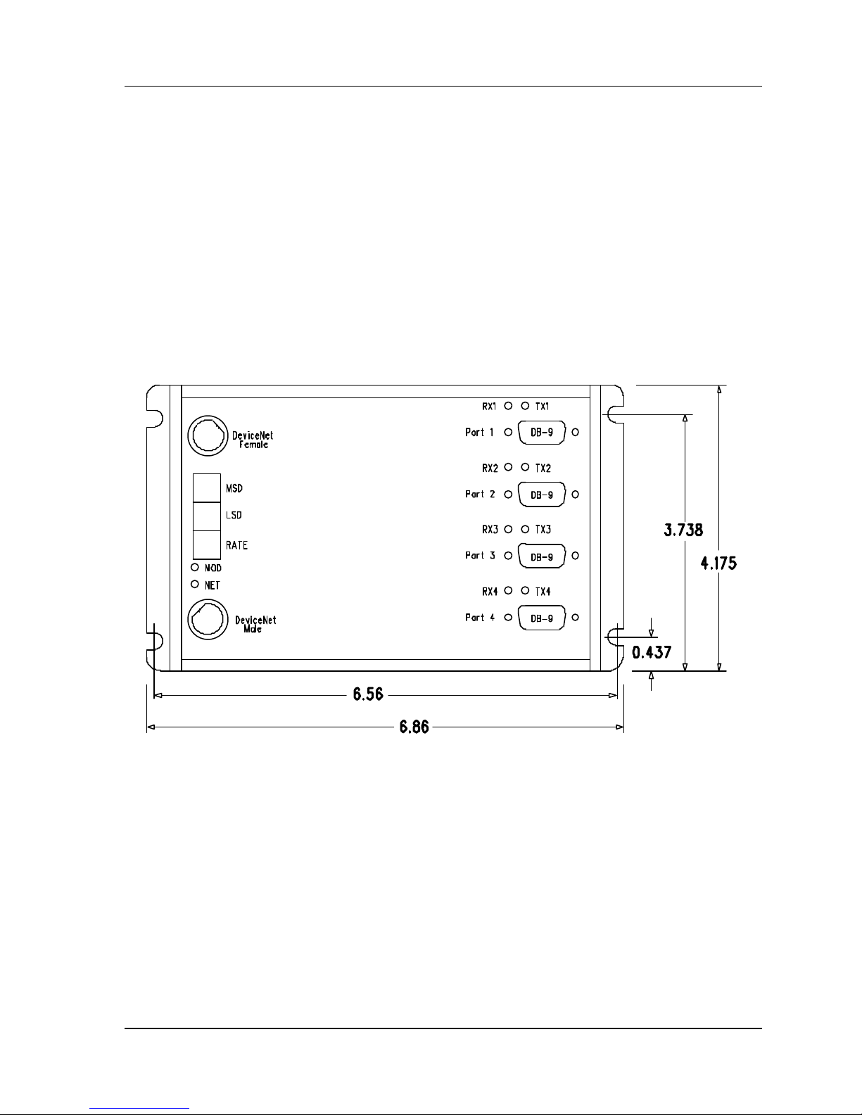
The W5-JDC4 consists of an IP20, aluminum, panel-mounted enclosure.
The W5-JDC4 contains two LED’s to indicate the status of the device and the status of the network.
The device can be connected to the main DeviceNet trunk line or to a drop line via a 5-pin female
plug-style connector. It also has eight (8) green LED’s to indicate the presence of activity on the
four (4) sets of RS -232 transmit and receive lines.
All power for the W5-JDC4 is derived from the DeviceNet power.
Figure 4-1 W5-JDC4 Outline Drawing – Top View
12
 Loading...