

Western Reserve Controls 1782-JDO User Manual

1782-JDO
DeviceNet-to-Optomux Gateway
User’s Manual
W estern Reserve Controls, Inc.

Western Reserve Controls, Inc. 1782-JDO User’s Manual
Although every effort has been made to insure the accuracy of this document, all information is
subject to change without notice. Western Reserve Controls, Inc. assumes no liability for any
errors or omissions in this document or for direct, indirect, incidental or consequential damage
resulting from the use of this document.
Rev 1.02
May 2004
Copyright © 2003-2004 WRC
Western Reserve Controls, Inc.
1485 Exeter Road
Akron OH 44306
330-733-6662 (Phone)
330-733-6663 (FAX)
sales@wrcakron.com (Email)
http://www.wrcakron.com (Web)
WRC is a trademark of Western Reserve Controls, Inc.
DeviceNet is a trademark of the Open DeviceNet Vendor Association (“ODVA”).
Optomux is a trademark of Opto22.
All other trademarks are property of their respective companies.

Western Reserve Controls, Inc. 1782-JDO User’s Manual
TABLE OF CONTENTS
1 OVERVIEW 4
1.1 FEATURES.............................................................................................................................................................................5
1.1 OPTOMUX COMMAND SUMMARY...........................................................................................................................................6
1.2 BASIC OPERATION.....................................................................................................................................................................6
1.2 DEFAULT DEVICE CONFIGURATION.................................................................................................................................7
1.3 PRODUCT VERSION AND EDS............................................................................................................................................7
2 QUICK START 8
2.1 HOW TO INSTALL A SERIAL NETWORK ............................................................................................................................8
2.2 HOW TO READ DISCRETE INPUT DATA FROM THE JDO................................................................................................8
2.3 HOW TO WRITE SERIAL OUTPUT DATA TO THE JDO..................................................................................................10
2.4 HOW TO CHANGE THE NODE ADDRESS.........................................................................................................................11
2.5 HOW TO CHANGE THE BAUD RATE................................................................................................................................11
3 GENERAL SPECIFICATIONS 12
4 HARDWARE INSTALLATION AND SET-UP 14
4.1 OVERVIEW.........................................................................................................................................................................14
4.2 LED OPERATION..............................................................................................................................................................14
4.2.1 DeviceNet LED’s..............................................................................................................................................................14
4.2.2 Serial Port LED’s.............................................................................................................................................................15
4.3 SERIAL PORT CONNECTOR..............................................................................................................................................16
4.4 DEVICENET CONFIGURATION.........................................................................................................................................16
4.4.1 DeviceNet Network Termination....................................................................................................................................16
4.4.2 DeviceNet Connection Wiring........................................................................................................................................16
4.4.3 RS485 Network Termination (1782-JDO-2) ................................................................................................................17
5 SOFTWARE CONFIGURATION AND SET-UP 18
5.1 SETTING UP SERIAL COMMUNICATIONS........................................................................................................................20
5.1.1 Reading the Data Frame Format...................................................................................................................................20
5.1.2 Setting up the serial link baud rate ................................................................................................................................20
5.2 SETTING UP DEVICENET COMMUNICATIONS ................................................................................................................20
5.2.1 Polled I/O ...........................................................................................................................................................................20
5.2.2 Reading the I/O Poll Response Data Size....................................................................................................................20
5.2.3 Reading the I/O Poll Data Size......................................................................................................................................21
5.2.4 Setting up the DeviceNet Baudrate ................................................................................................................................21
5.2.5 Autobaud Operation .........................................................................................................................................................21
5.2.6 Setting up the Connection Timer (EPR) .......................................................................................................................21
6 DEVICENET PROFILE, OBJECTS AND SERVICES 22
6.1 1782-JDO DEVICENET PROFILE....................................................................................................................................22
6.2 IDENTITY OBJECT , CLASS 1.............................................................................................................................................22
6.3 PARAMETER OBJECT , CLASS FHEX (15DEC)...................................................................................................................24
6.4 COMMON DEVICENET SERVICES ....................................................................................................................................25
7 ACCESSORIES AND OTHER WRC PRODUCTS 26

Western Reserve Controls, Inc. 1782-JDO User’s Manual
LIST OF TABLES
Table 1-1 I/O Message Types..................................................................................................6
Table 2-1 JDO Input Data Format (10 B1’s) ..............................................................................9
Table 2-2 Input Status/Error Byte........................................................................................... 10
Table 2-3.............................................................................................................................. 10
Table 2-4 DeviceNet Consume Assembly / Transmit Data Format ........................................... 11
Table 2-5 Baud Rate Selection .............................................................................................. 11
Table 4-1 Module Status LED (labeled MS)............................................................................ 15
Table 4-2 Network Status LED (labeled NS)........................................................................... 15
Table 4-3 RS -232 / RS-485 Connector Signals.......................................................................16
Table 4-4 Maximum Network Cable Lengths ...........................................................................16
Table 5-1 Configuration Parameter List.................................................................................. 18
Table 5-2 Serial Baud Rates.................................................................................................. 20
Table 6-1 DeviceNet Objects................................................................................................. 22
Table 6-2 Identity Object Class Attributes (Instance 0) ............................................................ 22
Table 6-3 Identity Object Instance Attributes (Instance 1)........................................................ 23
Table 6-4 Identity Object Common Services ........................................................................... 23
Table 6-5 Parameter Class Attributes (Instance 0).................................................................. 24
Table 6-6 Parameter Instance Attributes (Instances 1-7) ......................................................... 24
Table 6-7 Parameter Common Services ................................................................................. 24
Table 6-8 JDO Parameter Instanc es (Class F
Table 7-1 WRC Replacements, Spare Parts and Other Products............................................. 26
).................................................................... 24
hex
TABLE OF FIGURES
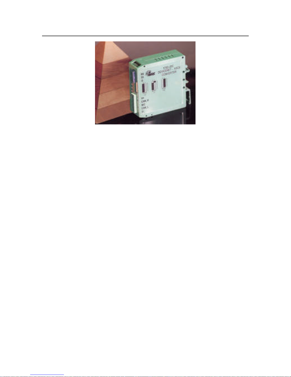
Figure 1-1 1782 -JDO ..............................................................................................................5
Figure 4-1 1782 -JDO Outline Drawing....................................................................................14
Figure 4-2 DeviceNet cable connector ....................................................................................17

Western Reserve Controls, Inc. 1782-JDO User’s Manual
PRELIMINARY
1 Overview
WRC’s 1782-JDO is a DeviceNet-to-RS485 serial link communications gateway and protocol
converter that provides a DeviceNet interface to Optomux B1 Brainboards. The JDO allows
the user to easily and conveniently connect and integrate existing B1 devices and their
associated I/O into a DeviceNet system.
Using the 1782-JDO you may communicate with the connected B1's in the same fashion as
the other DeviceNet products in the system. Data may be read/written using either I/O polling
or explicit messaging. Typically real-time data is read and written as I/O by the DeviceNet
Master via Polled I/O and parameters are read and written with the Explicit Messaging
technique.
The JDO gateway has several pre-defined Optomux commands built that it uses to
communicate with the B1 boards. As a user you do not need to know any details about the
Optomux protocol – you simply read and write discrete I/O data in your DeviceNet Master’s
I/O tables. To get started you need to fill in the appropriate configuration Parameters in the
JDO Parameter list to define your B1 Brainboard system and some general set-up attributes
and then place the JDO in your DeviceNet Master’s scan table. The JDO builds its owns
internal B1 scan list and starts communicating with the B1 boards. The JDO then translates
discrete I/O data between the DeviceNet polled I/O data and the Optomux B1 protocol
format.
You can connect up to 10 B1 brainboards to the JDO. The DeviceNet Master reads 3 bytes of
data from the JDO (1 status and 2 input data bytes) and writes 2 bytes of discrete output data
to the JDO for each brainboard.
The 1782-JDO is defined as a Communications Adapter device on the DeviceNet system. It
has a 3-pin plug connector for connection to a RS485/422 converter that then connects to the
to and from host connections of the port on a B1 and a 5-pin pluggable DeviceNet connector
for connections to the DeviceNet network. The serial port is configurable to run up to 38.4
kbaud. The device does auto baud rate selection when it is powered up on the DeviceNet
network. The 1782-JDO has one assigned DeviceNet address, which is set by a 6-position
DIPswitch on the unit. Other JDO parameters are software-configurable and are changed
from their default values by third-party DeviceNet configuration tools. Each 1782-JDO has 2
standard green/red DeviceNet LED’s for module status and network status and two green
LED’s to indicate RS485 transmit and receive activity. The RS485 link may be connected in a
point-to-point fashion to a single device, or to multiple devices in the standard RS485
convention.
This manual applies to 1782-JDO software versions 1.08 and later.
4
Western Reserve Controls, Inc. 1782-JDO User’s Manual
PRELIMINARY
Figure 1-1 1782-JDO
1.1 Features
The 1782-JDO has the following features:
•Translates messages and data between DeviceNet and up to 10 Opto22 B1 devices
•ODVA Conformance tested to DeviceNet Spec 2.0
•Defined as a DeviceNet Communications Device Profile 12 (C
•Autobaud operation
•Polled I/O and Explicit Messaging
•Software Configurable Parameters for serial port operation
•Software Configurable Parameters to define the B1 system
•DeviceNet address selection via DIP switches
•DIN rail mount
•Pluggable 5-pin DeviceNet connection
•Pluggable RS -485 3-pin connection
•2 standard DeviceNet module and network status LED’s
•Serial transmit and receive green LEDs
•Powered from DeviceNet 11-25 Vdc network power
•Serial port baud rate up to 38.4k baud
hex
)
5

Western Reserve Controls, Inc. 1782-JDO User’s Manual
PRELIMINARY
1.1 Optomux Command Summary
The JDO supports the following B1 commands:
• Power-up Clear (command A)
• Reset (command B)
• Enhanced Digital Watchdog (command m)
• Configure Positions (command G)
• Read Module Configuration (command j)
• Write Outputs (command J)
• Read Status (command M)
1.2 Basic Operation
The JDO operates as the DeviceNet front-end to the Optomux B1 brainboards. The
Device Net Master can receive and send data to and from the 1782-JDO via the methods
described in this section. It formats and sends the data to the B1s and accepts responses
from the B1, which are reformatted and passed back to the DeviceNet system as required. In
short, the JDO behaves like an Optomux scanner that is connected to DeviceNet.
The JDO has one DeviceNet address. All DeviceNet messages to the JDO are sent to this
address. All DeviceNet messages to and from the B1’s are sent to the JDO DeviceNet
assembly objects using poll commands.
The JDO Parameter Object allows you to define the specific operation of each JDO and the
attached B1’s. These parameters include all the set -up required for the serial comm. link.
The following chart defines the various messaging methods used for data types at your serial
device and a brief explanation follows.
Table 1-1 I/O Message Types
Typical Data Polled Cyclic Bit-Strobe Change-of-State Explicit Message
Commands √√
Status √√
Parameters √√
The general sequence of events and operation is explained below:
1. Configure the JDO for the number of brainboards (type B1) to be connected and the
input/output definition of each.
2. Each B1 has 9 associated parameters, including it Optomux address, input/output
6

Western Reserve Controls, Inc. 1782-JDO User’s Manual
PRELIMINARY
configuration, watchdog operation, etc. Set these parameters for each one.
3. Set up the rest of the parameters, as appropriate.
4. Note: Once the JDO is configured, it must be reset to complete the set up and
configuration of the B1’s.
5. Determine the DeviceNet I/O command and response data sizes – 3 bytes input and 2
bytes output data for each B1 – by reading the JDO Produce and Consume Sizes in
read-only Parameters 5 and 6.
6. Enter the JDO DeviceNet I/O sizes into your Master scanner and map its I/O into the
scanner’s I/O data table.
7. Once the DeviceNet scanner starts scanning the network, the JDO will start a sequence
of continuous reads and writes of each connected B1 to receive and transmit its output
and input data.
8. The JDO will continuously update its DeviceNet produce buffer asyncronously with B1
input data and provide updated information to the DeviceNet scanner via the Polled I/O
Response technique.
• The input data will be placed in the input field in the order as the B1’s are listed in the
Parameter list of the JDO.
9. Once the control system is put in run mode, the JDO will take the output data received
from the DeviceNet Master in the Poll Command and sent the output data to each B1.
• The output data will be read from the output field (consume data) in the order as the
B1’s are listed in the Parameter list of the JDO.
1.2 Default Device Configuration
The 1782-JDO DeviceNet address is read from the switches and is set to 63 and the baud
rate is set to Autobaud at the factory. All other parameters are software settable. The default
settings for the 1782-JDO are provided in the discussion of the Parameter Object and Table
5-1.
1.3 Product version and EDS
This manual applies to 1782-JDO versions 1.08 and higher. An EDS (Electronic Data Sheet)
for the 1782-JDO, is shipped with your device or is available on WRC’s web site:
http://www.wrcakron.com/.
7

Western Reserve Controls, Inc. 1782-JDO User’s Manual
PRELIMINARY
2 Quick Start
To quickly install your 1782-JDO in your DeviceNet system, follow the
instructions below . For more details, see Section 4.
1. Connect your DeviceNet network cable to a 5-pin female (Phoenix-type) plug according
to DeviceNet cable wiring specifications
2. Make sure that the DeviceNet network is terminated properly.
3. The JDO Node Address (MacID) is set to 63 at the factory. Make sure no other device on
the network is set to 63, or change the JDO address to one that is not currently used (see
Section 2.4 below).
4. The JDO baud rate is set to Autobaud operation at the factory. See Section 2.5 below to
change it to a fixed baud rate if desired.
5. Make sure that there is power on the DeviceNet network and plug the cable into the
1782-JDO.
6. The 1782-JDO will undergo its initialization sequence, flashing both LED’s red and green.
After approximately 5 seconds, the Module Status LED (labeled “MS”) will flash green.
The Network Status LED (labeled “NS”) will remain off. This condition occurs while the
JDO is attempting to synchronize to the network baudrate (autobaud).
7. The Module Status LED (“MS”) will go on solid after the Device successfully determines
the network baudrate. This requires devices on the network attempting to communicate
with each other. The Network Status LED (labeled “NS”) will begin to flash green. If it
turns solid red, check for a duplicate MacID on the network. If it remains off, make sure
that there are other devices trying to communicate on the network.
8. Once the Master recognizes the unit on the link and allocates the connection (initiates
communications), The Network Status LED will be solid green. The device is now being
actively scanned.
9. The 1782-JDO is now operating on the network.
2.1 How to Install a Serial Network
1. The communication between your serial device(s) and the 1782-JDO is an RS -485 2-wire
differential network. The B1’s are 4-wire RS -422 devices.
2. Connect one end of the cable to the JDO using the 3-point terminal plug provided. Note
the terminal markings on the JDO case.
3. Connect the JDO SIG+ signal wire to the TH+ and FH+ terminals on the first B1.
4. Connect the JDO SIG- signal wire to the TH - and FH- terminals on the first B1.
5. Turn on power to the serial device and the JDO.
Note: Opto22 and WRC recommend an external converter to make the interconnection
between the JDO and a Brainboard a RS -422 connection.
2.2 How to Read Discrete Input Data from the JDO
1. Set up the receive size of your connection to equal the (Max Number of B1 Devices * 3
(+1 if the Max Number is odd)) (set in Parameter 4) in your Master’s scan table. This
8
 Loading...