

Western Reserve Controls 1782-JDC User Manual

1782-JDC
DeviceNet Serial Gateway
User’s Manual
W
estern Reserve Controls, Inc.

Western Reserve Controls, Inc. 1782-JDC User’s Manual
Although every effort has been made to insure the accuracy of this document, all information is
subject to change without notice. Western Reserve Controls, Inc. assumes no liability for any
errors or omissions in this document or for direct, indirect, incidental or consequential damage
resulting from the use of this document.
Document 25.0
Rev 5.13
September 2011
Copyright © 2000-2011 WRC
Western Reserve Controls, Inc.
1485 Exeter Road
Akron OH 44306
330-733-6662 (Phone)
330-733-6663 (FAX)
sales@wrcakron.com (Email)
http://www.wrcakron.com (Web)
WRC is a trademark of Western Reserve Controls, Inc.
DeviceNet is a trademark of ODVA, Inc.
All other trademarks are property of their respective companies.
i

Western Reserve Controls, Inc. 1782-JDC User’s Manual
TABLE OF CONTENTS
1. OVERVIEW ........................................................................................................................................................ 4
1.1
F
EATURES
1.2
P
RODUCT FAMILY SELECTION
1.3
D
EVICENET SYSTEM ARCHITECTURE
1.4
B
ASIC OPERATION
1.4.1 Polled I/O ..................................................................................................................................................... 6
1.4.2 Explicit Messages ......................................................................................................................................... 6
1.4.3 Cyclic Input Message ................................................................................................................................... 6
1.4.4 Change-of-State, or COS ............................................................................................................................. 7
1.5
D
EFAULT DEVICE CONFIGURATION
1.6
P
RODUCT VERSION AND
2. QUICK START ................................................................................................................................................... 8
2.1
H
OW TO INSTALL AND ESTABLISH DEVICENET COMMUNICATIONS
2.2
H
OW TO CHANGE THE NODE ADDRESS
2.3
H
OW TO CHANGE THE BAUD RATE
2.4
H
OW TO INSTALL A SERIAL NETWORK
2.5
H
OW TO READ SERIAL DEVICE INPUT DATA FROM THE
2.6
H
OW TO WRITE SERIAL OUTPUT DATA TO THE
3. GENERAL SPECIFICATIONS ...................................................................................................................... 12
4. HARDWARE INSTALLATION AND SET-UP ............................................................................................ 14
4.1
O
VERVIEW
4.2
LED O
4.2.1 DeviceNet LEDs ......................................................................................................................................... 15
4.2.2 Serial Port LEDs ........................................................................................................................................ 15
4.3
S
ERIAL PORT CONNECTOR
4.4
D
EVICENET CONFIGURATION
4.4.1 DeviceNet Network Termination ................................................................................................................ 16
4.4.2 DeviceNet Connection Wiring .................................................................................................................... 17
4.4.3 RS485 Network Termination (1782-JDC-2) .............................................................................................. 17
......................................................................................................................................................... 5
........................................................................................................................... 5
................................................................................................................ 5
............................................................................................................................................. 6
................................................................................................................... 7
EDS ............................................................................................................................ 7
................................................................... 8
............................................................................................................. 8
................................................................................................................... 8
.............................................................................................................. 9
JDC ............................................................................. 9
JDC ....................................................................................... 10
...................................................................................................................................................... 14
PERATION
............................................................................................................................................. 15
.............................................................................................................................. 16
.......................................................................................................................... 16
5. SOFTWARE CONFIGURATION AND SET-UP ......................................................................................... 18
5.1
S
ETTING UP SERIAL COMMUNICATIONS
5.1.1 Setting up the serial link baud rate ............................................................................................................ 20
5.1.2 Setting up the receive delimiter .................................................................................................................. 20
5.1.3 Setting up the transmit delimiter ................................................................................................................ 20
5.1.4 Setting up the Data Frame Format ............................................................................................................ 21
5.1.5 Setting up the Receive Character Buffer Length ........................................................................................ 21
5.1.6 Setting up the Transmit Character Buffer Length ...................................................................................... 21
5.1.7 Setting up the Pad Mode ............................................................................................................................ 21
5.1.8 Setting up the Pad Character ..................................................................................................................... 22
5.1.9 Using the Swap Bytes Mode ....................................................................................................................... 22
5.1.10 Transmitting Serial Data ....................................................................................................................... 23
5.1.11 ASCII Receive Data and Pad Mode....................................................................................................... 23
5.2
S
ETTING UP DEVICENET COMMUNICATIONS
5.2.1 Polled I/O ................................................................................................................................................... 24
5.2.2 Cyclic and Change-of-State I/O ................................................................................................................. 24
5.2.3 Setting up the DeviceNet I/O Connections ................................................................................................. 25
5.2.4 Setting up the Connection Timer (EPR) ..................................................................................................... 25
........................................................................................................... 20
................................................................................................... 24
ii

Western Reserve Controls, Inc. 1782-JDC User’s Manual
5.2.5 Autobaud Operation .................................................................................................................................. 25
5.2.6 Setting up the DeviceNet Baudrate ............................................................................................................ 26
A. DEVICENET PROFILE, OBJECTS AND SERVICES .................................................................................... 27
A.1 1782-JDC D
A.2 S
A.3 I
A.4 P
A.5 C
ERIAL
DENTITY OBJECT, CLASS
ARAMETER OBJECT, CLASS
OMMON DEVICENET SERVICES
EVICENET PROFILE
I/O P
OLLED DATA FORMATS
...................................................................................................................... 27
............................................................................................................... 28
1 ............................................................................................................................. 29
F
HEX
(15
DEC
) ...................................................................................................... 30
..................................................................................................................... 33
B. ACCESSORIES AND OTHER WRC PRODUCTS .......................................................................................... 34
C. FREQUENTLY ASKED QUESTIONS .............................................................................................................. 36
D. TROUBLESHOOTING ....................................................................................................................................... 39
LIST OF TABLES
T
ABLE
1-1 I/O M
T
ABLE
2-1 B
T
ABLE
2-2 D
T
ABLE
2-3 S
T
ABLE
2-4 D
T
ABLE
4-1 M
T
ABLE
4-2 N
T
ABLE
4-3 RS-232/485 C
TABLE
4-4
T
ABLE
4-5 M
T
ABLE
5-1 C
T
ABLE
5-2 S
T
ABLE
A-1 D
T
ABLE
A-2 P
T
ABLE
A-3 P
T
ABLE
A-4 I
T
ABLE
A-5 I
T
ABLE
A-6 I
T
ABLE
A-7 P
T
ABLE
A-8 P
T
ABLE
A-9 P
T
ABLE
A-10 JDC P
T
ABLE
B-1 WRC R
ESSAGE TYPES
AUD RATE SELECTION
EVICENET CONSUME ASSEMBLY / SERIAL TRANSMIT DATA STRING
ERIAL RECEIVE STATUS/ERROR BYTE
EVICENET CONSUME ASSEMBLY / TRANSMIT DATA STRING
ODULE STATUS
ETWORK STATUS
RS
422/485
AXIMUM NETWORK CABLE LENGTHS
ONFIGURATION PARAMETER LIST
ERIAL BAUDRATES
EVICENET OBJECTS
OLL PRODUCE DATA
OLL CONSUME DATA
DENTITY OBJECT CLASS ATTRIBUTES (INSTANCE
DENTITY OBJECT INSTANCE ATTRIBUTES (INSTANCE
DENTITY OBJECT COMMON SERVICES
ARAMETER CLASS ATTRIBUTES (INSTANCE
ARAMETER INSTANCE ATTRIBUTES (INSTANCES
ARAMETER COMMON SERVICES
CONNECTOR SIGNALS
ARAMETER INSTANCES (CLASS
EPLACEMENTS, SPARE PARTS AND OTHER PRODUCTS
..................................................................................................................................... 6
................................................................................................................................ 9
...................................................................................................... 10
................................................................... 11
LED (
LABELED
LED (
LABELED
ONNECTOR SIGNALS
MS) ....................................................................................................... 15
NS) ...................................................................................................... 15
............................................................................................................. 16
................................................................................................................. 16
...................................................................................................... 16
............................................................................................................. 19
.................................................................................................................................... 20
................................................................................................................................. 27
(ASCII R
(ASCII T
ECEIVE STRING
RANSMIT STRING
) ....................................................................................... 28
) .................................................................................... 28
0) ................................................................................. 29
1) ........................................................................... 29
...................................................................................................... 29
0) ......................................................................................... 30
1-7) .............................................................................. 30
............................................................................................................... 30
F
) .............................................................................................. 31
HEX
....................................................... 10
.................................................................. 35
TABLE OF FIGURES
F
IGURE
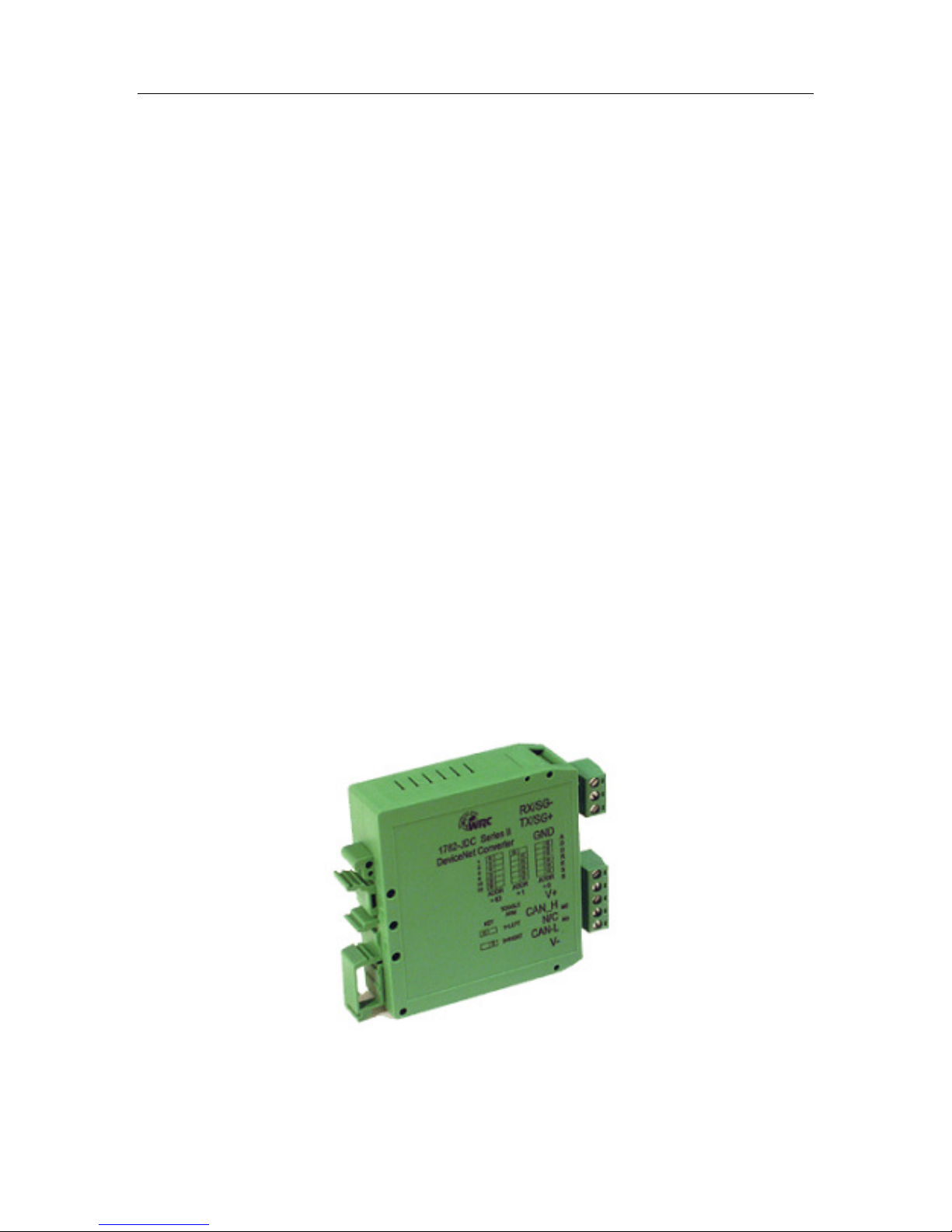
1-1 1782-JDC .................................................................................................................................................... 4
F
IGURE
4-1 1782-JDC O
F
IGURE
4-2 D
EVICENET CABLE CONNECTOR
UTLINE DRAWING
.................................................................................................................. 14
................................................................................................................ 17
iii
Western Reserve Controls, Inc. 1782-JDC User’s Manual
1. Overview
The 1782-JDC is a family of DeviceNet-to-serial link communications gateways that provide a
flexible DeviceNet interface to a wide variety of ASCII devices. The JDC allows the user to
easily and conveniently connect and integrate peripheral products with RS232, RS422 or
RS485 serial ports into a DeviceNet system.
Using the JDC you may communicate with the connected peripheral devices in the same
fashion as the other DeviceNet products in the system. Data may be read/written using either
I/O polling or explicit messaging. Typically real-time data is read and written as I/O by the
DeviceNet Master via Polled I/O and parameters are read and written with the Explicit
Messaging technique.
The 1782-JDC is defined as a Communications Adapter device on the DeviceNet system. It
has a 3-pin plug connector for connection to RS232 (JDC-1) or RS485 (JDC-2) or a 5-pin plug
connector for connection to RS422/485 (JDC-4) interface port on your device and a 5-pin
pluggable DeviceNet connector for connections to the DeviceNet network. The device does
baud rate selection automatically when it is powered up on a network. The 1782-JDC has one
assigned DeviceNet address, which is set by a 6-position DIP switch on the unit. Other JDC
parameters are software-configurable and are changed from their default values by third-party
DeviceNet configuration tools. Each 1782-JDC has 2 standard green/red DeviceNet LED’s for
module status and network status and two green LED’s to indicate RS232/422/485 transmit
and receive activity.
The RS232 version may be used for point-to-point connection to a single serial device. The
RS422/485 version may be connected in a point-to-point fashion to a single device, or to
multiple devices in the standard RS422/485 convention.
The JDC is a general-purpose gateway that is completely device-independent. The JDC does
not interpret the data being transmitted across it, and so the transferred messages may
contain data of any nature or definition. This allows you to use the same device for a wide
variety of DeviceNet-serial interface applications.
This manual applies to 1782-JDC version 5.
Figure 1-1 1782-JDC
4

Western Reserve Controls, Inc. 1782-JDC User’s Manual
1.1 Features
The 1782-JDC has the following features:
• Translates messages and data between DeviceNet and a serial peripheral device
• ODVA Group 2 Only Slave
• Defined as a DeviceNet Communications Device Profile 12 (C
• Autobaud operation
• Polled I/O and Explicit Messaging
• Software Configurable Parameters for serial port operation
• Special mode performs byte swapping of serial message for AB PLC compatibility
• Address selection via DIP switches
• DIN rail mount
• Pluggable 5-pin DeviceNet connection
• Pluggable RS-485 2-pin connection / RS-232 3-pin connection / RS-422 5-pin connection
• 2 standard DeviceNet module and network status LED’s
• 2 serial transmit and receive LED’s
• Powered from DeviceNet 11-25 Vdc network power
• ASCII string length up to 124 bytes
• Serial port baud rate up to 38.4k baud
• Network electrical isolation
hex
)
1.2 Product Family Selection
There are 3 members of the 1782-JDC family:
o 1782-JDC-1 Isolated RS-232
o 1782-JDC-2 Isolated RS-485
o 1782-JDC-4 Isolated RS-422/485
1.3 DeviceNet System Architecture
A DeviceNet network is a distributed I/O system that may contain many different products
from several different vendors. Products may be configured uniformly, as clusters or as
distributed clusters. Up to 64 devices, including the master may be attached to a single
DeviceNet network. Any of these, except the master, may be a JDC. A typical system will
include a master, such as a PLC or industrial PC, and multiple slave devices, including a
1782-JDC with connected peripheral devices.
5

Western Reserve Controls, Inc. 1782-JDC User’s Manual
1.4 Basic Operation
The JDC operates as the DeviceNet front-end to the serial device(s). Connecting the JDC to a
single device, that device can then be assigned by the system implementer to one specific
master. The DeviceNet Master can receive and send data to and from the 1782-JDC via the
methods described in this section. It formats and sends the data to the device and likewise
accepts responses from the device, which are reformatted and passed back to the DeviceNet
system as required.
The JDC has one DeviceNet address. All DeviceNet messages to the JDC itself (to read /
write its internal data) are sent to this address. All DeviceNet messages to and from the serial
device are sent to the JDC DeviceNet assembly objects using poll commands.
The JDC Parameter Object allows you to define the specific operation of each JDC. These
parameters include all the set-up required for the serial comm. link.
The following chart defines the various messaging methods used for “typical” data types at
your serial device and a brief explanation follows.
Table 1-1 I/O Message Types
Typical Data Polled Cyclic Bit-Strobe Change-of-State Explicit Message
Commands
Status
Parameters
√√√√ √√√√
√√√√ √√√√
√√√√
√√√√
√√√√
1.4.1 Polled I/O
The DeviceNet Master uses the JDC’s predefined polled IO connection to send input and
output data to the JDC. The input data to the JDC has a one-byte record number, a one-byte
length indicator and up to 124 additional bytes of transmit data. When a poll is received and
the record has changed since the last poll was sent, the JDC sends the associated transmit
data out the serial port to the remote ASCII device. When the JDC receives serial data from a
device on the serial link, the poll response data to the Master contains a one byte record
number, then a one byte status number that reflects errors or events on the bus, a one byte
length indicator that is the length of the message in the response and up to 124 bytes of
received data. The record number is incremented in the poll response when new data is
received on the serial link. The status byte is zero if no errors occurred.
1.4.2 Explicit Messages
As mentioned, explicit messages are typically used to read and write configuration data. This
data allows the JDC to change its internal operating parameters such as baudrate and parity.
The JDC does not allow for direct communication to the serial ports using explicit messaging.
1.4.3 Cyclic Input Message
Cyclic I/O is the function by which a slave device sends its input data to the master at a
specific time period without the host explicitly requesting it. When the specified time interval
(defined by you) elapses, the user-specified input data are transmitted to the master. This
data is the same format as a poll response.
6

Western Reserve Controls, Inc. 1782-JDC User’s Manual
1.4.4 Change-of-State, or COS
COS I/O is the function by which a slave device sends its input data to the master when
defined input data changes without the host explicitly requesting it. In the case of the JDC, this
occurs when the delimiter character is asynchronously received from the serial device. This
data is the same format as a poll response.
1.5 Default Device Configuration
The 1782-JDC DeviceNet address is read from the switches and is set to 63 at the factory. All
other parameters are software settable. The default settings for the 1782-JDC are provided in
the discussion of the Parameter Object.
1.6 Product version and EDS
This manual applies to 1782-JDC-x version 5 and higher. An EDS (Electronic Data Sheet) for
the 1782-JDC, is shipped with your device or is available on WRC’s web site:
http://www.wrcakron.com/.
7

Western Reserve Controls, Inc. 1782-JDC User’s Manual
2. Quick Start
To quickly install your 1782-JDC in your DeviceNet system, follow the instructions below. For
more details, see Section 4.
2.1 How to Install and Establish DeviceNet Communications
1. Connect your DeviceNet network cable to a 5-pin female (Phoenix-type) plug according to
DeviceNet cable wiring specifications
2. Make sure that the DeviceNet network is terminated properly.
3. The JDC Node Address (MacID) is set to 63 at the factory. Make sure no other device on
the network is set to 63, or change the JDC address to one that is not currently used (see
below).
4. The JDC baud rate is set to Autobaud operation at the factory. See below to change it to a
fixed baud rate if desired.
5. Make sure that there is power on the DeviceNet network and plug the cable into the 1782JDC.
6. The 1782-JDC will undergo its initialization sequence, flashing both LED’s red and green.
After approximately 5 seconds, the Module Status LED (labeled “MS”) will flash green.
The Network Status LED (labeled “NS”) will remain off. This condition occurs while the
JDC is attempting to synchronize to the network baud rate.
7. The Module Status LED (“MS”) will go on solid after the Device successfully determines
the network baud rate. This requires devices on the network attempting to communicate
with each other. The Network Status LED (labeled “NS”) will begin to flash green. If it
turns solid red, check for a duplicate MacID on the network. If it remains off, make sure
that there are other devices trying to communicate on the network.
8. Once the Master recognizes the unit on the link and allocates the connection (initiates
communications), The Network Status LED will be solid green. The device is now being
actively scanned.
9. The 1782-JDC is now operating on the network.
2.2 How to Change the Node Address
1. Set the 6-position DIP switch to the binary number representing the desired Node
Address, 0-63. (Note: Address 0 is often reserved for a Master device.)
2. Power cycle the unit by unplugging and reconnecting the DeviceNet cable.
NOTE: T
Reset command is received from the Master.
he new address will not become effective until the unit is power cycled or a
2.3 How to Change the Baud Rate
The Baud Rate is set to autobaud at the factory. The baud rate can be changed through your
configuration tool in its normal manner to any baud rate except autobaud. This is due to the
fact that autobaud is not provided for in the DeviceNet specification. If you need to set the
8

Western Reserve Controls, Inc. 1782-JDC User’s Manual
baud rate to autobaud, you must do it via the parameter object. The definition is included in
the EDS file for easy configuration. Just use your configuration tool to access the device
parameters. The baud rate is parameter 7. Select the proper baud rate and upload the
parameter to the device. If your configuration tool does not support EDS parameter
configuration, you will have to perform the operation manually. To do this, set the parameter
Class 15 (F
NOTE:
unit is power cycled or a reset command is received by the Identity Object (Class 1,
Instance 0, reset).
), instance 7, attribute 1 to the value in Table 2-1.
hex
If you change the baud rate, the new baud rate will not become effective until the
Table 2-1 Baud Rate Selection
Baud Rate
Value
0 125k
1 250k
2 500k
3 Autobaud
Baud
Rate
2.4 How to Install a Serial Network
1. The communication between your serial device(s) and the 1782-JDC is a RS232 3-wire,
RS485 2-wire or 5-wire RS422/485 differential network. Connect an appropriate cable to
your device.
2. Connect the other end of the cable to the JDC using the 3-point or 5-point terminal plug
provided. Note the terminal markings on the JDC case. See Figure 4-1.
3. Turn on power to the serial device and the JDC.
4. Set up the ASCII buffer sizes on the JDC. (The defaults are 20 and 20). If more than 20
bytes are required for the transmit or receive buffers, set parameters 5 and 6 in your
configuration file to the buffer size you need for your ASCII data (NOTE: this will modify
the IO message size. You will need to reconfigure the poll / COS / cyclic transmit and
receive data sizes if you modify the ASCII buffer size from the default value. In many
configuration tools, this will unmap the data in your scanner’s scan table. They must be
remapped in order to be able to process the data in your PLC or software) These
parameters can be reached in the Parameter Class 15 (F
1 if you need to configure these manually (See Table A-10).
), Instances 5 and 6, Attribute
hex
2.5 How to Read Serial Device Input Data from the JDC
1. Set up the receive size of your connection to equal the (Max Number of Receive Chars
+ 3) in your Master’s scan table. The default value should be 23 (20+3).
2. Map the data from your IO response to your scanners memory map. The device’s
response is byte aligned. The first byte indicates the receive record of the data. The
second byte contains the JDC's serial status indicator (00 is normal). The third byte
contains the length of the message being transmitted by the JDC. The subsequent bytes
contain the serial buffer data from the serial input until and including the latest received
9

Western Reserve Controls, Inc. 1782-JDC User’s Manual
delimiter. The response is only updated when the delimiter is received or a buffer overflow
occurs. Every time the buffer is updated (e.g. the delimiter received or an overflow
condition) the record number will be incremented. The data is only valid up to the received
delimiter in your memory map. Data after the received delimiter may contain invalid data.
3. Direct the master to begin polling the JDC. Once the first delimiter is received, the
master’s memory will reflect data received by the JDC. The data returned will have the
following pattern:
Table 2-2 DeviceNet Consume Assembly / Serial Transmit Data String
BYTE MEANING
Byte 1 Record Counter
Byte 2 Serial Port Status
Byte 3 String Length (number of data bytes)
Byte 4 ASCII Character 1
….
Byte 23 ASCII Character 19
….
Byte 127 ASCII Character 124
The status/error byte represents the status of the ASCII data record received from the ASCII
device. This byte is defined as follows:
Table 2-3 Serial Receive Status/Error Byte
Byte Value Meaning
0 No error
1 Buffer Overflow
2 Parity Error
3 Buffer Overflow and Parity Error
2.6 How to Write Serial Output Data to the JDC
1. Set up the transmit size of your connection to equal the buffer size of the ASCII transmit
buffer plus 2. (Default is 22 bytes)
2. Map the IO transmit data of the JDC. The first byte of the JDC’s IO transmit array is the
record number. This value should be set to 0 at the beginning of communications. The
second byte is a length indicator, followed by the number of data bytes. The ensuing bytes
are the data that you wish to send to the JDC. If the length is set to 0 the JDC will send
10

Western Reserve Controls, Inc. 1782-JDC User’s Manual
all of the consecutive bytes up to and including the delimiter after the transmit record
number has changed. If the length is non-zero, the JDC will send up to the number of
bytes specified by the length without regard to the transmit delimiter and ignoring
any “junk” characters after the specified amount of bytes. The format is:
Table 2-4 DeviceNet Consume Assembly / Transmit Data String
BYTE MEANING
Byte 1 Record Counter
Byte 2 String Length (number of data bytes)
Byte 3 ASCII Character 1
Byte 4 ASCII Character 2
….
Byte 21 ASCII Character 19
….
Byte 126 ASCII Character 124
3. Begin scanning the JDC. Enter data that you want to send on the serial link. On receipt of
a change to the record number, the JDC will transmit the data. If any data is in the
receive buffer, the received data will be returned as a poll response. (If the sequence
number is the same as the previous response, the JDC will not re-send the string.)
NOTE: If using the Byte-Swap Mode (Parameter 10 set to enabled) all strings being sent must
have the length set. Using a zero length will prevent the byte swapping from occurring.
11
 Loading...