

Page 1
WESTERN PROCESS COMPUTERS, INC.
2033 W. North Lane • Suite 14 • Phoenix, AZ 85021-1900 • (800) 997-7245 • FAX (602) 997-7248 • [email protected]
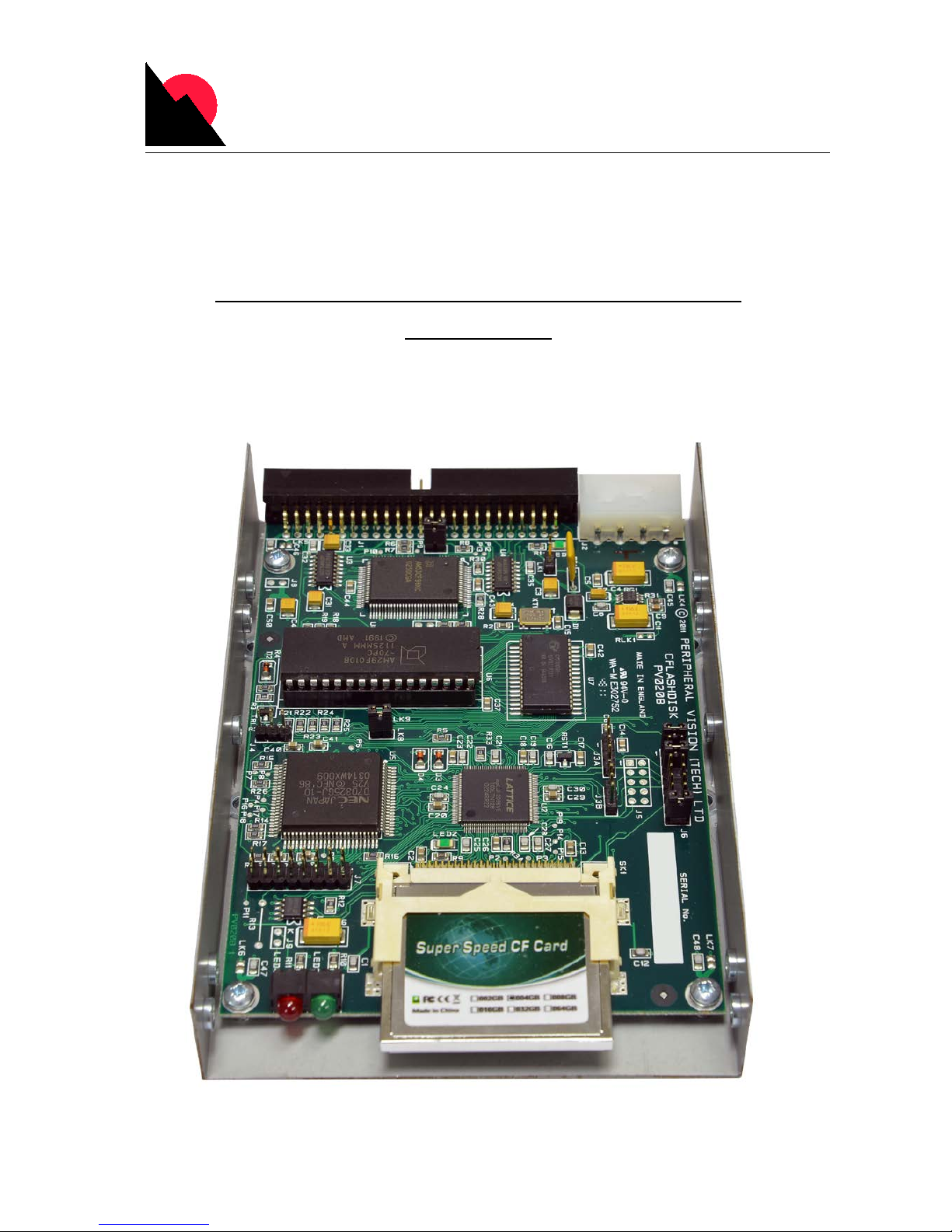
CFHDD - SCSI Hard drive Replacement
User Guide
Page 2

Contents
• CFHDD (SCSI) Hard drive replacement. Pre-formatted Dual Logical.
• 16GB Industrial Grade CF (compact flash) card. Required for 512Bit Dual Logical.
• 12” Molex 5V Power Extension cable.
Features
• 3.5 inch form factor
• Standard 50 pin SCSI1/2 interface
• 10 Mbytes/sec SCSI burst rate
• Internal active SCSI termination, disabled /enabled by jumper
• Spare certified CF cards are available through Western Process Computers.
Jumper Settings
• Termination is enabled with jumper LK2. The last device on your SCSI cable must be
terminated. When a jumper is present on LK2, SCSI termination is ENABLED
• Jumper LK1 implements the export of termination power. Note: Internal terminators
always have power.
• Jumper J6 sets the SCSI ID and enables/disables the serial port. For the CFHD
application, you may ignore the serial port.
• The CFHDD is formatted Dual Logical. SCSI address set for 4 (jumper on position 3)
will show as 4 and 2, SCSI address 5 (jumper on position 1 and 3) will show as 5 and 3.
Connections
• Connect the SCSI cable – Note that pin 1 of the cable is at the edge of the PCB, away
from the power connector.
• Connect the 5V power using the Molex power extension provided. Note that a standard
5V/12V disk power lead can be used here as the 12V pin is a no-connect on the board.
• The PCB mounts in the standard 3.5” form factor tray. It requires 5V supplied via a
standard Molex 4 pin disk power connector.
• CFHDD mounts with the same hardware using the 50pin SCSI cable, no adaptor required.
Make sure the SCSI address ID and correct termination is maintained, either drive or
cable end.
Operation
• The front panel GREEN LED will flash if the CF card is not inserted. The green heartbeat
LED will flash while power is applied. The RED LED indicates drive access.
• The CFHDD will replac e the standard (Seagate) Honeywell Dual Logical hard drive and
is pre-formatted to be installed and “synched” to the customers History Module.
•
CF Chips must be pre-formatted using Honeywell HVTS prior to Synch procedure.
•
The SPC card must be HW- “D” or greater, FW- “H” or greater for dual logical drives.
Page 3
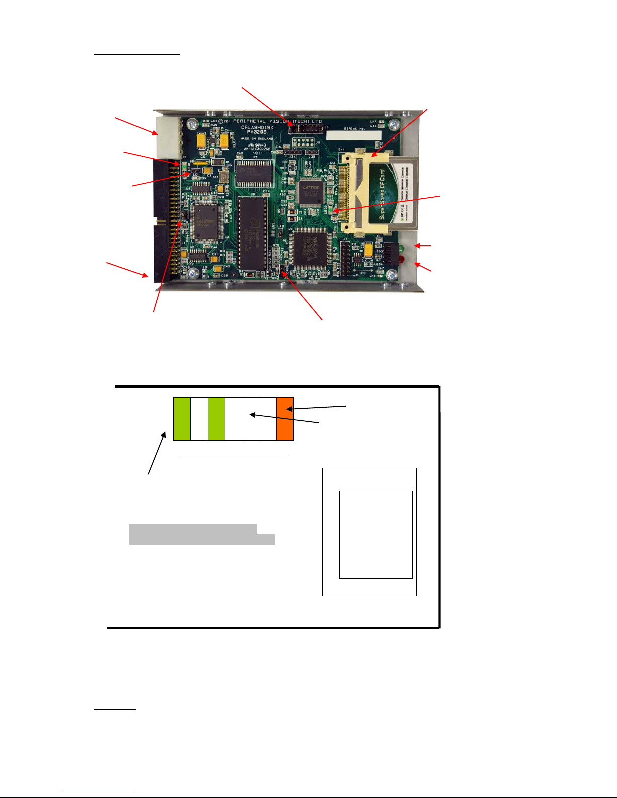
CFHDD Layout
• Set the SCSI ID as required at J6
NOTE: Honeywell uses SCSI addresses 4 & 5 for the physical addressing of
the hard drives. Corresponding addresses 2 & 3 are virtual addresses formatted
into the dual logical dr ive. Drive addr essed SCSI 5 will show 5 & 3 and a drive
addressed SCSI 4 will show 4 & 2 on a status display.
J6 – position 1
SCSI ID = 0 no jumpers
SCSI ID = 1 jumper position 1
SCSI ID = 2 jumper position 2
SCSI ID = 3 jumper position 1 & 2
SCSI ID = 4 jumper position 3
SCSI ID = 5 jumper position 1 & 3
SCSI ID = 6 jumper position 2 &3
SCSI ID = 7 jumper position 1,2 &3
CF SOCKET
Unused positions
Example shows SCSI ID - 5
Serial port enable
(not used for HD)
SCSI Termination Jumper LK2 –
jumper present = termination
Export Termination
power jumper LK1
Termination power
Present LED
CF card socket
Power connector –
only 5V required
SCSI connector—
NOTE pin 1
SET SCSI ID – J6
Heartbeat LED
Disk coming r ead y LED
(green)
D
isk Activity LED (red)
Serial Port J4
Page 4

CFHDD SYNCH
Install drive tray and power on the new drive.
Wait for the HM to indicate it sees the new DRIVE(s) by viewing the HM STATUS
DETAIL, select DISK DRIVE 5 (line), and select the target “View Object Detail”.
On the right side, make sure there is a status of something other than a message indicating it
is not available. Status of “not initialized” appears in red text. This status can also be checked
after the start of the “synch” process to verify initialization progress per volume.
Go to the COMMAND PROCESSOR
In the next step, I am assuming you are replacing the redundant drives 4 & 2 using LCN HM
node # 32
Type:
OFFLINE PN:32 2
OFFLINE PN:32 4
Wait a few minutes. You can check the HM status with command: STATUS PN:32
Drives 2 & 4 should show OFFLINE.
Type SYNCH PN:32
Type STATUS PN:32
Drive 2 - SYN_IP
Drive 3 - OK
Drive 4 - SYN_IP
Drive 5 - OK
* Regarding SYN_IP (synchronization in progress), note that the Synch operation for
redundant or dual redundant drives can last for an hour or more depending on the amount of
history configured for this HM.
Insta
llation:
Use M3x3mm screws (and no longer) to install the tray.
WESTERN PROCESS COMPUTERS, INC.
2033 W
. North Lane • Suite 14 • Phoenix, AZ 85021-1900 • (800) 997-7245 • FAX (602) 997-7248 •
Maintenance:
Due to memory cycle limitations of CompactFlash, WPC recommends replacement and
re-synchronization of the CF card every 5 years. Chip manufacturers can change code, we
also recommend additional certified media be ordered from WPC.
 Loading...