

Western Electric 6071 B Instructions For Use Manual
RADIO
Western
AMPLIFIER
INSTRUCTIONS
Electric
FREQUENCY
No.
Cu'eljr-rva
FOR
B
6071
USE
Printed in
U.S.A.
Instruction Bulletin No.
728
The equipment
described
in
this Bulletin
was
designed and
developed
for the
Wes/47r71
Electric
Company
by.
BELL TELEPHONE
LABORATORIES
RADIO FREQUENCY
AMPLIFIER
No. 607
1 B
CONTENTS
Page
Page
INTRODUCTION
1 Installation of
Amplifier
Tubes....
12
Power
Requirements (Table)
1 Bias Voltages
and
Plate
Current
(Table)
13
GENERAL
DESCRIPTION 2
Amplifier Input
Circuit 2
TUNING
ADJUSTMENTS
13
Amplifier Tubes
2
Preliminary
13
Amplifier
Output
Circuit 2
Amplifier
Input
Circuit
13
Harmonic
Suppression and Antenna
Neutralizing
and
Amplifier
Output
Coupling
2
Tuning
14
Monitoring
Circuit 2
Coupling
Circuit
Tuning
14
Power
Circuits
2
Adjustment
of
Output
Transformer
Power
Control and Protection Cir-
Turns
15
cuits
3
Antenna
Tuning
15
Formula
for Coupling
Capacity
15
INSTALLATION
3
Final
Tuning
Operations
16
General
3
Typical
Meter
Readings
(Table)
16
Ground
System 4
Summary
of
Adjustments
16
Antenna
5
Formula
for Antenna
Current
17
Power
and Control
Connections... 5
Operation
at
Reduced
Power
17
Radio Frequency
Input
Connections 5
Formula
for
Efficiency
(Foot-
Audio
Frequency
Connections
5
note)
17
Transformer
Connections
6
Miscellaneous
Installation
Notes.. .
Change
of Transmitter
Nameplates
6
6
MODULATION
At Normal
Power
18
18
At
Reduced
Power
19
PRELIMINARY
ADJUSTMENTS
OF
POWER
CIRCUITS
Power
Supply
Circuits
Fuse
Ratings
(Table)
Preheat
Rectifier
Tubes
Delay
Relay
Grid Bias
Load
Resistances
6
6
7
7
7
9
MONITORING
Monitoring
Levels
Maximum
Monitoring
Levels
(Table)
Monitoring
Circuit
Impedance
19
19
19
19
Door
Switch and Filament
Relays..
9
Plate
Rectifier
Contactor,
Surge and
OPERATING
PROCEDURE
20
Filter
Resistance
Relays
9
Starting
the
Equipment
20
Grid
Bias Marginal
Relay
9
Stopping
the
Equipment
20
Overload
Relay
10
Overload
Relay
Reset
20
Normal
and
Overload
Current
Operating
Use
of
Meters
20
(Table)
10
Operating
Use of
Load
Resistance.
21
General
12
Definition
of "Resistance
Intro-
duced"
(Footnote)
21
PRELIMINARY
ADJUSTMENTS
OF
RADIO
FREQUENCY
CIR-
CONNECTION
TO OTHER
EQUIP-
CUITS
12 MENT
22
General
12 Connection
to
Transmitter
Other
Adjustment
of Antenna
Impedance 12 Than
No. 12B
22
Value
of
Antenna
Condenser Connection
to Amplifier
of
Higher
(Table) 12
Power
22
I
MAINTENANCE
General
Care
of the
Cabinet
Cleaning
Variable
Air
Condensers
Relays
and Magnetic
Contactors
23
Vacuum
Tubes
23
Vacuum
Tube
Sockets
24
Repair
of Thermocouples
24
Additional
Routine
24
CONTENTS
(Continued)
Page
Page
22
APPARATUS
INFORMATION
27
22
23
23
LOCATION
OF TROUBLE
25
General
25
Power
Control
Circuit
25
Fuses
25
Reduced
or
No
Radiation
26
Distortion
26
Noise
27
II
SPARE
PARTS
27
General
List
of Spare Parts for
the
6071B Amplifier
27
Special List
of Spare
Parts for the
1000
Watt Equipment
28
Special List
of
Spare
Parts
for the
500
Watt Equipment
28
Special List
of Spare Parts for
the
250
Watt
Equipment
28
ENGINEERING
SERVICE AND
IN-
FORMATION
FOR
ORDERING
REPLACEMENTS
29
RADIO
FREQUENCY
AMPLIFIER
No.
6o7113
Introduction
The Western
Electric No.
6071B Amplifier
is
a radio -frequency ampli-
fier
designed
for connection
to
a
Western
Electric
No. 12B
or other Radio
Transmitter
capable
of delivering
100
watts.
It may be operated
at any
frequency
from
550
to 3000 kilocycles
and
will
deliver
250,
500
or
1000
watts
of
completely
modulated
carrier into
a
suitable
antenna. It is com-
posed of
a
No.
71B Amplifier
plus miscellaneous
apparatus such
as
vacuum
tubes,
fuses, etc.,
required for
operation.
The No.
71B Amplifier
consists
of a metal cabinet,
similar to that of
the
No.
12B
Radio Transmitter,
containing
the
radio
-frequency circuits,
complete power
supply
equipment
and all the necessary
control and pro-
tective
circuits.
As the
amplifier is
completely
a -c. operated, no motor -
generators,
batteries
or other
external power
equipment are required.
The amplifier
is
designed
to operate
on
220
-volt, 50-
or 60 -cycle, three-
phase
power
supply.
The following
table gives the total power required
for
operation
at the
three
output ratings
in the
standby
and operating
conditions.
The
power
factor is
90
per cent.
Output
Rating
1000 watts
500 watts
250
watts
Full
Operation
4000 watts
2400
watts
1500
watts
A schematic
diagram
of the
amplifier
circuit is
shown in Figure
1.
The
amplifier
consists
of two
tubes
operating in
a balanced
push-pull
cir-
cuit,
a
circuit
for suppressing
radio
-frequency
harmonics,
and provision
for
efficiently
coupling
the
output
to an
antenna.
Separate rectifiers
pro-
vide
the necessary
direct
current
to the plate
and grid
circuits.
Control
and
protective
circuits
interlock
with
those
of the associated
radio
trans-
mitter
to provide
protection
to the
equipment
and
the operating personnel.
The Nos.
302C,
303C.
and
304C Radio
Transmitting
Equipments
(250,
500,
and
1000
watt
output,
respectively)
each
consist
of a
No.
12B
Radio
Transmitter
and
a
No.
71B
Amplifier with
their
necessary
accessories.
These
equipments
are
supplied with
tubes,
tube
sockets, condensers,
etc.
for
the power
output
requested.
They may
be
operated
at reduced
power
by
simple
adjustments.
The power
rating
may
be changed
by
the substi-
tution
of the
proper
tubes,
tube sockets
and
other components.
[1]
GENERAL
DESCRIPTION
Amplifier
Input
Circuit
The radio
-frequency
input
voltage
is
obtained
from
the tuned. input
transformer
(L1B)
coupled
to the
output
of
the associated
radio
trans-
mitter.
The input
energy is
dissipated
in
resistances
(R1B and
R2B)
which
are
in
tapped
sections
to permit
adjustment
to the value required
to produce
the
necessary
radio
-frequency
grid voltage
across
the tuned
circuit.
Amplifier
Tubes
The
amplifier
employs
two
radiation -cooled
vacuum
tubes
(V1B and
V2B)
operating
as class
"B" in
a
balanced push-pull
circuit, the tubes
being
biased
to approximate
cut-off.
Amplifier
Output
Circuit
The
plates of
the
tubes
operate into
a
tuned output transformer
con-
taining
a thermoammeter
(M5B)
to facilitate
tuning and neutralizing.
Harmonic
Suppression
and
Antenna
Coupling
Harmonic
suppression
and
antenna
coupling is
accomplished
by the
network
consisting
of L3B,
C11B, C12B and L4B which
couples the
trans-
mitter
to
the antenna
and suppresses
the
radio
-frequency
harmonics.
Meters
(M6B
and
M7B) necessary
to
facilitate
tuning
are provided
in
this circuit.
A resistance
(R8B)
of 100
ohms
is included,
which
may be
connected
by means
of a
link
(D14B)
to serve
as a
load
for
testing at
times when
it is
not permissible
or
desirable
to energize
the
antenna.
Monitoring
Circuit
An audio
output
transformer
(T4B)
connected in
the high
voltage
return
lead provides
ample audio
power
for monitoring purposes.
Power
Circuits
The filaments
of all tubes
operate
on alternating
current. The
filament
transformer primary
voltage
is measured
by a voltmeter (M1B)
and is
maintained
at 200 volts
by
adjustment
of
the
variable
auto -transformer
(T6B).
Grid bias voltage
is
supplied
by a
single full -wave mercury
vapor
rectifier
tube (V9B)
.
The output
of this rectifier
is passed through
a
two
-
section filter
and dissipated
in
an
adjustable resistance
(R10B).
Plate
power for
the amplifier
tubes is
supplied
by a
three-phase
full -
wave
mercury
vapor
rectifier
employing six
tubes (V3B
to
V8B, incl.) .
The
output
of this
rectifier is filtered
by
a
single -section
filter.
[2]
6
O
D7.IB
TO
D7.7B
\ÿ
d
7
O
L-------

r
Power
Control
and
Protection
Circuits
The power
control
circuits consist
of
a combination
of relays
arranged
to energize
the
various power
circuits
of
the amplifier
in
the
correct
sequence
and to provide
the necessary
delay
before
applying
plate
voltage
to
the
rectifier tubes.
The
amplifier
is completely
energized
automatically
by the
operation
of
the
"Master
Control"
switch
located on
the
No. 12B
Radio Transmitter,
if the
"Main Power
Disconnect"
(D1B)
and the
"Filaments" (D3B) switches
are
closed,
and
when the "High
Voltage"
switches
on both the transmitter
and
amplifier
units
are
"On."
For semi-
automatic
starting, the
"High
Voltage"
switches
are left
in the
"Off"
position
when the
"Master Control"
switch
is closed.
After
the
control
circuits
have functioned,
the
starting operation
may
be completed
by
closing the "High
Voltage"
switches.
(See
"Control
Circuit Sequence
Chart,"
Figure 2).
The
protection circuits
(of the
No. 71B
Amplifier)
consist of
the
fol-
lowing relays and
fuses to protect the
equipment
and personnel.
The
door switch
relay (S3B)
removes bias
and plate
voltages
whenever
a
door
switch
(D7B)
is
operated
either
in the
No. 12B Radio
Transmitter
or the
No.
71B
Amplifier.
The grid
bias marginal relay
(S5B) removes the
plate voltage
when
the bias
voltage is below
a proper
value and prevents application
of the
plate voltage when
the
bias
voltage is low.
The overload
relay (S6B) removes the plate
voltage
when an overload
beyond
the
safe capacity of the
rectifier occurs.
The current
demanded
by modulation
peaks and supplied
by
the
filter condenser
does not pass
through this
relay and
cause
unnecessary operation.
The
surge
relay (S7B) and
the
filter resistance
relay (S8B)
are pro-
vided to short out a
resistance, used to limit the condenser
charging cur-
rent,
after the condenser has assumed
its full charge. It
is necessary to
limit
this charging current to prevent excessive
loads
on the
rectifier tubes
and false operation of the overload relay.
Fuses
are provided in the 220
-volt
a -c. circuits and in the
rectifier out-
put circuits as
additional protection
to the
apparatus against circuit
defects.
INSTALLATION
General
The installation
of the
No.
71B Amplifier in conjunction with the
No.
12B Radio
Transmitter, being a
typical
case, is herein dealt with in detail.
Installation in
conjunction with a transmitter other than
the
No.
12B
should
be
facilitated
by these
instructions.
The
No.
302C, 303C,
or 304C Radio
Transmitting
Equipments should
be installed
in accordance with
the installation
drawings
furnished.
The
[3]
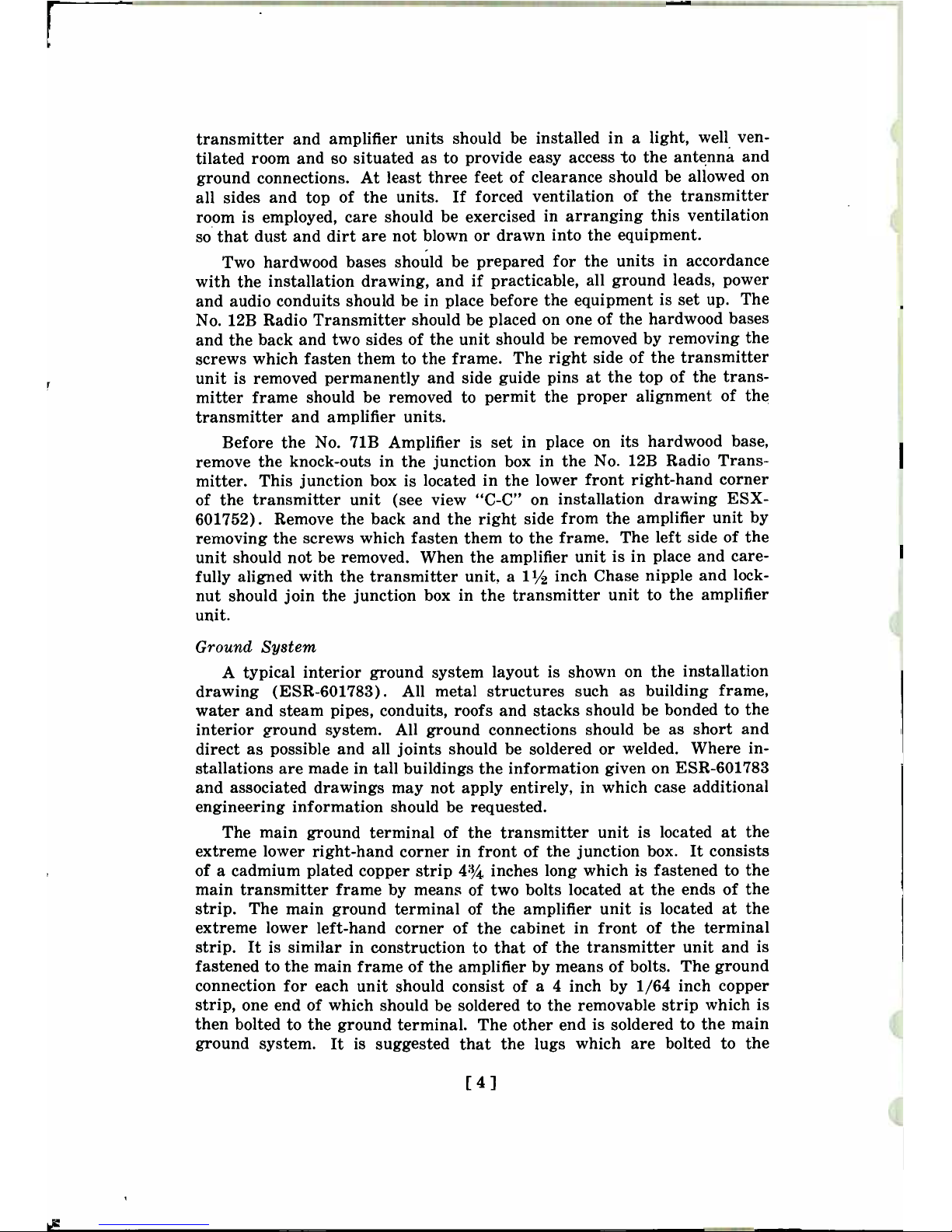
transmitter
and amplifier
units
should be
installed in a
light,
well ven-
tilated room and so situated
as to
provide easy access
to the
antenna
and
ground
connections.
At
least three
feet
of
clearance
should be
allowed on
all sides and top
of the
units. If
forced ventilation
of the transmitter
room
is
employed,
care
should be exercised
in
arranging
this ventilation
so that dust
and dirt are
not blown or
drawn into the
equipment.
Two
hardwood bases should
be prepared
for the units
in accordance
with
the
installation
drawing,
and if practicable,
all
ground leads,
power
and
audio conduits should
be in place
before the equipment
is set up.
The
No.
12B
Radio Transmitter should
be
placed
on one of
the
hardwood bases
and
the
back and two
sides of the unit
should
be removed
by removing
the
screws
which fasten them to the frame.
The
right side of
the transmitter
unit is removed
permanently and side guide
pins at the
top of the
trans-
mitter frame
should be removed to permit
the proper
alignment
of the
transmitter
and amplifier units.
Before
the
No.
71B Amplifier is
set in
place on
its hardwood
base,
remove the
knock-outs in
the junction
box
in
the
No. 12B Radio Trans-
mitter. This
junction
box
is
located in
the
lower
front right-hand
corner
of
the
transmitter unit (see view "C
-C"
on
installation
drawing
ESX-
601752).
Remove the back
and
the
right side
from the
amplifier
unit
by
removing the screws
which fasten
them to the
frame. The
left side
of the
unit
should
not
be removed.
When the
amplifier
unit
is in place
and care-
fully aligned
with the transmitter unit, a
11/2 inch Chase
nipple
and
lock -
nut
should
join the
junction
box
in
the
transmitter
unit to the
amplifier
unit.
Ground System
A
typical
interior ground system
layout is
shown
on the
installation
drawing
(ESR-601783). All
metal
structures
such
as building
frame,
water and
steam
pipes,
conduits,
roofs and stacks should
be bonded
to the
interior
ground
system. All
ground
connections
should be as
short and
direct as possible
and all joints
should
be soldered or
welded. Where
in-
stallations are made in
tall
buildings
the
information given
on
ESR-601783
and
associated
drawings may not apply
entirely,
in
which case
additional
engineering information should be requested.
The
main
ground
terminal of the transmitter unit
is
located at the
extreme
lower
right-hand corner in front
of
the
junction box.
It
consists
of
a cadmium
plated
copper strip
43/4
inches
long which is
fastened to the
main transmitter frame
by means of two bolts
located at the
ends of the
strip.
The main ground terminal
of
the amplifier unit
is located at the
extreme
lower
left-hand
corner of the cabinet
in front of the terminal
strip. It
is similar in construction
to that of
the transmitter
unit and
is
fastened
to the
main
frame
of the amplifier
by means of bolts.
The
ground
connection for each
unit should consist of a 4
inch by 1/64 inch
copper
strip, one
end of
which
should be
soldered
to the removable
strip
which is
then
bolted to the ground
terminal. The other end
is soldered to
the main
ground
system.
It is suggested
that
the
lugs
which
are
bolted
to
the
[4]
ground
terminal
in
the
transmitter
unit
be temporarily
removed
while
soldering
the ground
strip.
All
ground
connections
should
be
as short
and
direct
as possible.
Antenna
The
No. 71B
Amplifier
can
be operated
with
an
antenna
of
any
resist-
ance
and
reactance,
but
where
antennas
of
less
than
12 or
more
than
90
ohms
are
encountered,
additional
engineering
information
should
be
requested.
The
antenna
lead-in
from
the
grounding
switch
is connected
to terminal
27
located
on top
of the
amplifier
unit.
Copper
tubing
is recom-
mended
for this
purpose.
Power
and
Control
Connections
A
1 -inch conduit
should
be
installed
from
the
service
entrance
to
the
junction
box
in
the
transmitter
unit
and
three
No. 8
B&S gauge
BRC
wires
should
be pulled
through
from
the
220 -volt,
3 -phase,
50-
or
60 -cycle
power
supply.
These
wires
connect
to
terminals
1,
2
and
3
of the
amplifier
terminal
block.
Connect
terminals
2 and 3
of the
amplifier
to terminals
1
and
2, respectively,
of the
transmitter
terminal
block.
Using
No.
14 B&S
gauge
BRC
wire connect
terminals
4, 5, 6
and 7
of the
transmitter
unit
to terminals
4, 5, 6 and
7,
respectively,
of the
amplifier
unit.
Radio
-Frequency
Input Connections
In the
No. 12B
Radio
Transmitter
open
link switch
D28A
and
remove
condensers C21A
from their
mounting
posts.
Connect
the
ground
strap
of the
transmitter
to terminal
26
of the
amplifier.
Connect
the
ungrounded
post just
vacated
by condensers
C21A
to terminal
25 of the
amplifier.
When
these
connections
are
complete,
link switch
D2A
may be
used to
connect
resistance
R12A into the
circuit
: that
is,
when this
link
is between
"3"
and
"4"
the resistance
is in circuit,
and
when between
"2" and "3"
the
resistance
is
out
of circuit.
Audio
-Frequency Connections
The
speech
input and
monitoring output
leads
should
be
run in
con-
duit and
brought out
near the terminal
blocks
in the transmitter
unit.
The
speech
input leads connect to
terminals
15 and
16
on
the transmitter
terminal
block and the
monitoring
output
leads connect
to
the
spare
terminals
13 and
14 on
the
transmitter
terminal
block.
Terminals
13 and
14
then
should
be connected to
terminals
9 and
10, respectively,
of the
amplifier
unit. A
No. 19 B&S gauge twisted
pair, rubber
and
lead
covered
cable per
KS -6531 should be
used
for all audio
leads.
Both ends
of the
lead
cable
sheath should
be bonded to the
ground
system
with a
No. 16
B&S
gauge
bare copper
wire
and
all conduits
should
be soldered
or
welded
to the ground
system. In
grounding the
lead cable
sheaths, terminal
10
of the transmitter
unit or
terminal
11 of the amplifier
unit may
be used.
[51
Transformer Connections
The heaviest transformer
(T5B)
is shipped
separately
and
must be
mounted
in its place in
the lower compartment.
Each transformer
ter-
minal
is marked
and
each
wire is
correspondingly
tagged.
Remove the
metal tags or slide them
back upon the
wires
to
avoid a chance
of short
circuiting,
and connect numbered
wires to the
correspondingly
numbered
transformer terminals.
Rectifier transformers (T3B and
T5B) are
equipped
with taps marked
with the primary voltage. The
line voltage should be
measured
at
regular
intervals during an operating
day, the
average
taken, and the
connections
to the transformer
taps made on that marked terminal
which is nearest to
the
average voltage.
Miscellaneous Installation
Notes
When the harmonic suppression coil
is fitted with an
internal
supple-
mentary coil it
is
shipped
with fiber
wedges
to protect
it from breakage.
Remove these
wedges before
energizing
the amplifier.
The equipment
is
shipped
with
condensers,
meters, and
other parts, all
of
which
are
appropriate for
the
frequency,
power
and antenna
impedance
specified in
the
order.
Change
of Transmitter
Nameplates
Certain
apparatus designation nameplates
on the
No.
12B Radio Trans-
mitter are changed
when
the
transmitter is
operated
in conjunction
with
the
No.
71B Amplifier.
The
new
nameplates and mounting screws
are
included
with
the equipment
and can be attached readily
with
a
screw-
driver. The nameplates
to
be substituted
are listed below
:
Original
New
Apparatus
Nameplate
Nameplate
Designation
Designation Designation
M3A
"Antenna
Current"
"Output
Current"
C19A
"Antenna
Tuning"
"Output
Tuning"
The correct
equipment nameplate also will
be
included
and should
be
mounted
in the
designated place in
the center of the front panel of
the
No.
12B
Radio Transmitter.
The
panel is drilled and tapped,
and
the
proper
screws
are provided for
this purpose.
PRELIMINARY
ADJUSTMENTS
OF
POWER
CIRCUITS
Power
Supply
Circuits
Open main
switch D1B
and install fuses
in
accordance
with the follow-
ing
table
which
gives
the
fuse
ratings
in
amperes.
[ 6 ]
 Loading...